Interfacing Analog to Digital Data Converters
|
|
|
- Marilynn Hines
- 9 years ago
- Views:
Transcription
1 Converters In most of the cases, the PIO 8255 is used for interfacing the analog to digital converters with microprocessor. We have already studied 8255 interfacing with 8086 as an I/O port, in previous section. This section we will only emphasize the interfacing techniques of analog to digital converters with The analog to digital converters is treaded as an input device by the microprocessor, that sends an initialising signal to the ADC to start the analogy to digital data conversation process. The start of conversation signal is a pulse of a specific duration. M Krishhna Kumar MAM/M3/LU9g/V1/2004 1

2 The process of analog to digital conversion is a slow process, and the microprocessor has to wait for the digital data till the conversion is over. After the conversion is over, the ADC sends end of conversion EOC signal to inform the microprocessor that the conversion is over and the result is ready at the output buffer of the ADC. These tasks of issuing an SOC pulse to ADC, reading EOC signal from the ADC and reading the digital output of the ADC are carried out by the CPU using 8255 I/O ports. M Krishhna Kumar MAM/M3/LU9g/V1/2004 2

3 The time taken by the ADC from the active edge of SOC pulse till the active edge of EOC signal is called as the conversion delay of the ADC. It may range any where from a few microseconds in case of fast ADC to even a few hundred milliseconds in case of slow ADCs. The available ADC in the market use different conversion techniques for conversion of analog signal to digitals. Successive approximation techniques and dual slope integration techniques are the most popular techniques used in the integrated ADC chip. M Krishhna Kumar MAM/M3/LU9g/V1/2004 3

4 General algorithm for ADC interfacing contains the following steps: 1. Ensure the stability of analog input, applied to the ADC. 2. Issue start of conversion pulse to ADC 3. Read end of conversion signal to mark the end of conversion processes. 4. Read digital data output of the ADC as equivalent digital output. M Krishhna Kumar MAM/M3/LU9g/V1/2004 4

5 Analog input voltage must be constant at the input of the ADC right from the start of conversion till the end of the conversion to get correct results. This may be ensured by a sample and hold circuit which samples the analog signal and holds it constant for a specific time duration. The microprocessor may issue a hold signal to the sample and hold circuit. If the applied input changes before the complete conversion process is over, the digital equivalent of the analog input calculated by the ADC may not be correct. M Krishhna Kumar MAM/M3/LU9g/V1/2004 5

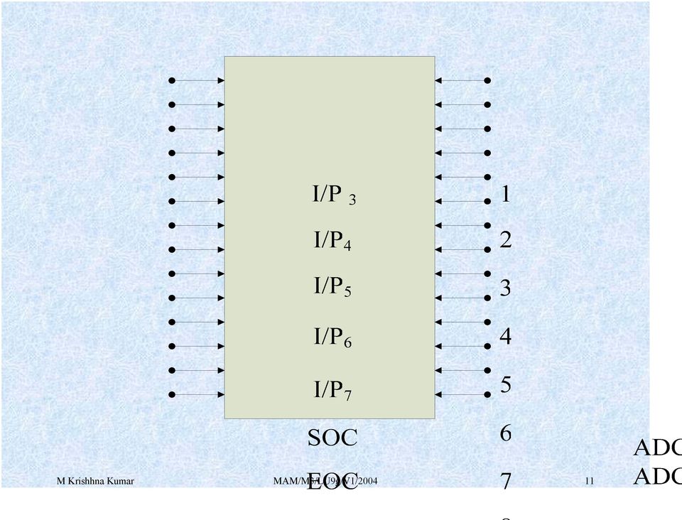
6 ADC 0808/0809 : The analog to digital converter chips 0808 and 0809 are 8- bit CMOS, successive approximation converters. This technique is one of the fast techniques for analog to digital conversion. The conversion delay is 100µs at a clock frequency of 640 KHz, which is quite low as compared to other converters. These converters do not need any external zero or full scale adjustments as they are already taken care of by internal circuits. These converters internally have a 3:8 analog multiplexer so that at a time eight different analog conversion by using address lines - M Krishhna Kumar MAM/M3/LU9g/V1/2004 6

7 ADD A, ADD B, ADD C. Using these address inputs, multichannel data acquisition system can be designed using a single ADC. The CPU may drive these lines using output port lines in case of multichannel applications. In case of single input applications, these may be hardwired to select the proper input. There are unipolar analog to digital converters, i.e. they are able to convert only positive analog input voltage to their digital equivalent. These chips do no contain any internal sample and hold circuit. M Krishhna Kumar MAM/M3/LU9g/V1/2004 7

8 Analog I/P selected C Address lines B A I / P 0 I / P 1 I / P 2 I / P 3 I / P 4 I / P 5 I / P 6 I / P Fig M Krishhna Kumar MAM/M3/LU9g/V1/2004 8

9 If one needs a sample and hold circuit for the conversion of fast signal into equivalent digital quantities, it has to be externally connected at each of the analog inputs. Vcc Supply pins +5V GND GND Vref + Reference voltage positive +5 Volts maximum. Vref _ Reference voltage negative 0Volts minimum. M Krishhna Kumar MAM/M3/LU9g/V1/2004 9

10 I/P 0 I/P 7 Analog inputs ADD A,B,C Address lines for selecting analog inputs. O 7 O 0 Digital 8-bit output with O 7 MSB and O 0 LSB SOC Start of conversion signal pin EOC End of conversion signal pin OE Output latch enable pin, if high enables output CLK Clock input for ADC M Krishhna Kumar MAM/M3/LU9g/V1/

11 M Krishhna Kumar MAM/M3/LU9g/V1/
12 C 8 Channel Analog Multiplexer B A SOC 256 R ladder and Switch tree CLOCK EOC O/P Latch O/P 8-bit O/P I / P 0 I / P 1 Control and Timing unit and S.A.R. I / P 2 I / P 3 I / P 4 I / P 5 I / P 6 I / P 7 Register V ref + V ref _ Enable Block Diagram of ADC 0808 / 0809 Address Lines M Krishhna Kumar MAM/M3/LU9g/V1/

13 CLOCK START ALE EOC OE O / P Timing Diagram of ADC 0808 M Krishhna Kumar MAM/M3/LU9g/V1/

14 Example: Interfacing ADC 0808 with 8086 using 8255 ports. Use port A of 8255 for transferring digital data output of ADC to the CPU and port C for control signals. Assume that an analog input is present at I/P 2 of the ADC and a clock input of suitable frequency is available for ADC. Solution: The analog input I/P 2 is used and therefore address pins A,B,C should be 0,1,0 respectively to select I/P 2. The OE and ALE pins are already kept at +5V to select the ADC and enable the outputs. Port C upper acts as the input port to receive the EOC signal while port C lower acts as the output port to send SOC to the ADC. M Krishhna Kumar MAM/M3/LU9g/V1/

15 Port A acts as a 8-bit input data port to receive the digital data output from the ADC. The 8255 control word is written as follows: D 7 D 6 D 5 D 4 D 3 D 2 D 1 D The required ALP is as follows: MOV AL, 98h ;initialise 8255 as OUT CWR, AL ;discussed above. MOV AL, 02h ;Select I/P 2 as analog OUT Port B, AL ;input. M Krishhna Kumar MAM/M3/LU9g/V1/

16 MOV AL, 00h ;Give start of conversion OUT Port C, AL ; pulse to the ADC MOV AL, 01h OUT Port C, AL MOV AL, 00h OUT Port C, AL WAIT: IN AL, Port C ;Check for EOC by RCR ; reading port C upper and JNC WAIT ;rotating through carry. IN AL, Port A ;If EOC, read digital equivalent ;in AL HLT ;Stop. M Krishhna Kumar MAM/M3/LU9g/V1/

17 Vref + Vref + CS + 5 V + 5 V Vcc Clock up A 2 D 0 D 7 PA 7 PA 0 PC 7 PC 0 EOC SOC O 7 O 0 ADC 0808 Analog I/P Voltage A 1 Reset V OE ALE A B GND C IORD PB 0 PB 1 IOWR PB 2 Interfacing 0808 with 8086 M Krishhna Kumar MAM/M3/LU9g/V1/

18 Interfacing Digital To Analog INTERFACING DIGITAL TO ANALOG CONVERTERS: The digital to analog converters convert binary number into their equivalent voltages. The DAC find applications in areas like digitally controlled gains, motors speed controls, programmable gain amplifiers etc. AD bit Multiplying DAC : This is a 16 pin DIP, multiplying digital to analog converter, containing R-2R ladder for D-A conversion along with single pole double thrown NMOS switches to connect the digital inputs to the ladder. M Krishhna Kumar MAM/M3/LU9g/V1/

19 OUT R FB OUT Vref in GND 3 14 V + MSB B 1 B AD NC NC B B 8 LSB B B 7 B B 6 Pin Diagram of AD 7523 M Krishhna Kumar MAM/M3/LU9g/V1/

20 LSB Interfacing Analog to Digital Data D 0 D 1 D 2 D 3 +5V (MSB) 2R R 1 R 2R 3 2R R R 5 2R 7 2R 2R R 2 R 4 R 6 R V 0 Fig: M Krishhna Kumar MAM/M3/LU9g/V1/

21 Interfacing Digital To Analog The pin diagram of AD7523 is shown in fig the supply range is from +5V to +15V, while Vref may be any where between -10V to +10V. The maximum analog output voltage will be any where between -10V to +10V, when all the digital inputs are at logic high state. Usually a zener is connected between OUT1 and OUT2 to save the DAC from negative transients. An operational amplifier is used as a current to voltage converter at the output of AD to convert the current out put of AD to a proportional output voltage. M Krishhna Kumar MAM/M3/LU9g/V1/
22 Interfacing Digital To Analog It also offers additional drive capability to the DAC output. An external feedback resistor acts to control the gain. One may not connect any external feedback resistor, if no gain control is required. EXAMPLE: Interfacing DAC AD7523 with an 8086 CPU running at 8MH Z and write an assembly language program to generate a sawtooth waveform of period 1ms with Vmax 5V. Solution: Fig shows the interfacing circuit of AD with 8086 using program gives an ALP to generate a sawtooth waveform using circuit. M Krishhna Kumar MAM/M3/LU9g/V1/
23 Example (cont..) ASSUME CS:CODE CODE SEGMENT START: MOV AL,80h ;make all ports output OUT CW, AL AGAIN: MOV AL,00h ;start voltage for ramp BACK : OUT PA, AL INC AL CMP AL, 0FFh JB BACK JMP AGAIN CODE ENDS END START M Krishhna Kumar MAM/M3/LU9g/V1/
24 +5V +10V R FB 8255A PA 7 PA 0 MSB LSB 4 11 OUT1 OUT2 1 2 VZ - + V 0 AD7523 CS 3 GND Fig: Interfacing of AD7523 M Krishhna Kumar MAM/M3/LU9g/V1/
25 In the above program, port A is initialized as the output port for sending the digital data as input to DAC. The ramp starts from the 0V (analog), hence AL starts with 00H. To increment the ramp, the content of AL is increased during each execution of loop till it reaches F2H. After that the saw tooth wave again starts from 00H, i.e. 0V(analog) and the procedure is repeated. The ramp period given by this program is precisely ms. Here the count F2H has been calculated by dividing the required delay of 1ms by the time required for the execution of the loop once. The ramp slope can be controlled by calling a controllable delay after the OUT instruction. M Krishhna Kumar MAM/M3/LU9g/V1/
NTE2053 Integrated Circuit 8 Bit MPU Compatible A/D Converter
 NTE2053 Integrated Circuit 8 Bit MPU Compatible A/D Converter Description: The NTE2053 is a CMOS 8 bit successive approximation Analog to Digital converter in a 20 Lead DIP type package which uses a differential
Digital to Analog and Analog to Digital Conversion
 Real world (lab) is Computer (binary) is digital Digital to Analog and Analog to Digital Conversion V t V t D/A or DAC and A/D or ADC D/A Conversion Computer DAC A/D Conversion Computer DAC Digital to
AUTOMATIC NIGHT LAMP WITH MORNING ALARM USING MICROPROCESSOR
 AUTOMATIC NIGHT LAMP WITH MORNING ALARM USING MICROPROCESSOR INTRODUCTION This Project "Automatic Night Lamp with Morning Alarm" was developed using Microprocessor. It is the Heart of the system. The sensors
Conversion Between Analog and Digital Signals
 ELET 3156 DL - Laboratory #6 Conversion Between Analog and Digital Signals There is no pre-lab work required for this experiment. However, be sure to read through the assignment completely prior to starting
CHAPTER 11: Flip Flops
 CHAPTER 11: Flip Flops In this chapter, you will be building the part of the circuit that controls the command sequencing. The required circuit must operate the counter and the memory chip. When the teach
DIGITAL-TO-ANALOGUE AND ANALOGUE-TO-DIGITAL CONVERSION
 DIGITAL-TO-ANALOGUE AND ANALOGUE-TO-DIGITAL CONVERSION Introduction The outputs from sensors and communications receivers are analogue signals that have continuously varying amplitudes. In many systems
ADC0808/ADC0809 8-Bit µp Compatible A/D Converters with 8-Channel Multiplexer
 ADC0808/ADC0809 8-Bit µp Compatible A/D Converters with 8-Channel Multiplexer General Description The ADC0808, ADC0809 data acquisition component is a monolithic CMOS device with an 8-bit analog-to-digital
DAC Digital To Analog Converter
 DAC Digital To Analog Converter DAC Digital To Analog Converter Highlights XMC4000 provides two digital to analog converters. Each can output one analog value. Additional multiple analog waves can be generated
Decimal Number (base 10) Binary Number (base 2)
 Binary Number (base 2)") LECTURE 5. BINARY COUNTER Before starting with counters there is some vital information that needs to be understood. The most important is the fact that since the outputs of a digital chip can only be
LECTURE 5. BINARY COUNTER Before starting with counters there is some vital information that needs to be understood. The most important is the fact that since the outputs of a digital chip can only be
Digital to Analog Converter. Raghu Tumati
 Digital to Analog Converter Raghu Tumati May 11, 2006 Contents 1) Introduction............................... 3 2) DAC types................................... 4 3) DAC Presented.............................
Micro-Step Driving for Stepper Motors: A Case Study
 Micro-Step Driving for Stepper Motors: A Case Study N. Sedaghati-Mokhtari Graduate Student, School of ECE, University of Tehran, Tehran, Iran n.sedaghati @ece.ut.ac.ir Abstract: In this paper, a case study
Interfacing To Alphanumeric Displays
 Interfacing To Alphanumeric Displays To give directions or data values to users, many microprocessor-controlled instruments and machines need to display letters of the alphabet and numbers. In systems
PART B QUESTIONS AND ANSWERS UNIT I
 PART B QUESTIONS AND ANSWERS UNIT I 1. Explain the architecture of 8085 microprocessor? Logic pin out of 8085 microprocessor Address bus: unidirectional bus, used as high order bus Data bus: bi-directional
ADS9850 Signal Generator Module
 1. Introduction ADS9850 Signal Generator Module This module described here is based on ADS9850, a CMOS, 125MHz, and Complete DDS Synthesizer. The AD9850 is a highly integrated device that uses advanced
Timer A (0 and 1) and PWM EE3376
 and PWM EE3376") Timer A (0 and 1) and PWM EE3376 General Peripheral Programming Model Each peripheral has a range of addresses in the memory map peripheral has base address (i.e. 0x00A0) each register used in the peripheral
Timer A (0 and 1) and PWM EE3376 General Peripheral Programming Model Each peripheral has a range of addresses in the memory map peripheral has base address (i.e. 0x00A0) each register used in the peripheral
8-Bit Flash Microcontroller for Smart Cards. AT89SCXXXXA Summary. Features. Description. Complete datasheet available under NDA
 Features Compatible with MCS-51 products On-chip Flash Program Memory Endurance: 1,000 Write/Erase Cycles On-chip EEPROM Data Memory Endurance: 100,000 Write/Erase Cycles 512 x 8-bit RAM ISO 7816 I/O Port
24-Bit Analog-to-Digital Converter (ADC) for Weigh Scales FEATURES S8550 VFB. Analog Supply Regulator. Input MUX. 24-bit Σ ADC. PGA Gain = 32, 64, 128
 for Weigh Scales FEATURES S8550 VFB. Analog Supply Regulator. Input MUX. 24-bit Σ ADC. PGA Gain = 32, 64, 128") 24-Bit Analog-to-Digital Converter (ADC) for Weigh Scales DESCRIPTION Based on Avia Semiconductor s patented technology, HX711 is a precision 24-bit analogto-digital converter (ADC) designed for weigh
24-Bit Analog-to-Digital Converter (ADC) for Weigh Scales DESCRIPTION Based on Avia Semiconductor s patented technology, HX711 is a precision 24-bit analogto-digital converter (ADC) designed for weigh
Part 1. MAX 525 12BIT DAC with an Arduino Board. MIDI to Voltage Converter Part1
 MIDI to Voltage Converter Part 1 MAX 525 12BIT DAC with an Arduino Board 1 What you need: 2 What you need : Arduino Board (Arduino Mega 2560) 3 What you need : Arduino Board (Arduino Mega 2560) Digital
Having read this workbook you should be able to: recognise the arrangement of NAND gates used to form an S-R flip-flop.
 Objectives Having read this workbook you should be able to: recognise the arrangement of NAND gates used to form an S-R flip-flop. describe how such a flip-flop can be SET and RESET. describe the disadvantage
150127-Microprocessor & Assembly Language
 Chapter 3 Z80 Microprocessor Architecture The Z 80 is one of the most talented 8 bit microprocessors, and many microprocessor-based systems are designed around the Z80. The Z80 microprocessor needs an
Microcomputers. Analog-to-Digital and Digital-to-Analog Conversion
 Microcomputers Analog-to-Digital and Digital-to-Analog Conversion 1 Digital Signal Processing Analog-to-Digital Converter (ADC) converts an input analog value to an output digital representation. This
DATA SHEET. TDA1543 Dual 16-bit DAC (economy version) (I 2 S input format) INTEGRATED CIRCUITS
 (I 2 S input format) INTEGRATED CIRCUITS") INTEGRATED CIRCUITS DATA SHEET File under Integrated Circuits, IC01 February 1991 FEATURES Low distortion 16-bit dynamic range 4 oversampling possible Single 5 V power supply No external components required
INTEGRATED CIRCUITS DATA SHEET File under Integrated Circuits, IC01 February 1991 FEATURES Low distortion 16-bit dynamic range 4 oversampling possible Single 5 V power supply No external components required
Chapter 6: From Digital-to-Analog and Back Again
 Chapter 6: From Digital-to-Analog and Back Again Overview Often the information you want to capture in an experiment originates in the laboratory as an analog voltage or a current. Sometimes you want to
Digital To Analog Converter with Sine Wave Output
 Digital To Analog Converter with Sine Wave Output Overview In this Lab we will build a resistive ladder network and use the BASIC Stamp to generate the digital data for the D/A conversions. PBASIC will
Analog/Digital Conversion. Analog Signals. Digital Signals. Analog vs. Digital. Interfacing a microprocessor-based system to the real world.
 Analog/Digital Conversion Analog Signals Interacing a microprocessor-based system to the real world. continuous range x(t) Analog and digital signals he bridge: Sampling heorem Conversion concepts Conversion
Features DISPLAY DECODING INPUT INTERFACING
 Data Sheet FN3158.8 4-Digit, LCD Display Driver The device is a non-multiplexed four-digit seven-segment CMOS LCD display decoder-driver. This device is configured to drive conventional LCD displays by
PC BASED PID TEMPERATURE CONTROLLER
 PC BASED PID TEMPERATURE CONTROLLER R. Nisha * and K.N. Madhusoodanan Dept. of Instrumentation, Cochin University of Science and Technology, Cochin 22, India ABSTRACT: A simple and versatile PC based Programmable
Experiments: Labview and RS232
 Experiments: Labview and RS232 September 2013 Dušan Ponikvar Faculty of Mathematics and Physics Jadranska 19, Ljubljana, Slovenia There are many standards describing the connection between a PC and a microcontroller
Analog-to-Digital Converters
 Analog-to-Digital Converters In this presentation we will look at the Analog-to-Digital Converter Peripherals with Microchip s midrange PICmicro Microcontrollers series. 1 Analog-to-Digital Converters
HD61202U. (Dot Matrix Liquid Crystal GraphicDisplay Column Driver)
") HD622U (Dot Matrix Liquid Crystal GraphicDisplay Column Driver) Description HD622U is a column (segment) driver for dot matrix liquid crystal graphic display systems. It stores the display data transferred
HD622U (Dot Matrix Liquid Crystal GraphicDisplay Column Driver) Description HD622U is a column (segment) driver for dot matrix liquid crystal graphic display systems. It stores the display data transferred
12-Bit Serial Daisy-Chain CMOS D/A Converter DAC8143
 a FEATURES Fast, Flexible, Microprocessor Interfacing in Serially Controlled Systems Buffered Digital Output Pin for Daisy-Chaining Multiple DACs Minimizes Address-Decoding in Multiple DAC Systems Three-Wire
The components. E3: Digital electronics. Goals:
 E3: Digital electronics Goals: Basic understanding of logic circuits. Become familiar with the most common digital components and their use. Equipment: 1 st. LED bridge 1 st. 7-segment display. 2 st. IC
Using the HT46R46 I/O Ports to Implement Half-Duplex SPI Communication
 Using the HT46R46 I/O Ports to Implement Half-Duplex SPI Communication D/N: HA0150E Introduction This application explains how to use two I/O lines on the HT46R46 to implement half-duplex SPI communication.
MICROPROCESSOR. Exclusive for IACE Students www.iace.co.in iacehyd.blogspot.in Ph: 9700077455/422 Page 1
 MICROPROCESSOR A microprocessor incorporates the functions of a computer s central processing unit (CPU) on a single Integrated (IC), or at most a few integrated circuit. It is a multipurpose, programmable
LC2 MOS Quad 8-Bit D/A Converter AD7226
 a FEATURES Four 8-Bit DACs with Output Amplifiers Skinny 20-Pin DIP, SOIC and 20-Terminal Surface Mount Packages Microprocessor Compatible TTL/CMOS Compatible No User Trims Extended Temperature Range Operation
STEPPER MOTOR SPEED AND POSITION CONTROL
 STEPPER MOTOR SPEED AND POSITION CONTROL Group 8: Subash Anigandla Hemanth Rachakonda Bala Subramanyam Yannam Sri Divya Krovvidi Instructor: Dr. Jens - Peter Kaps ECE 511 Microprocessors Fall Semester
TIMING DIAGRAM O 8085
 5 TIMING DIAGRAM O 8085 5.1 INTRODUCTION Timing diagram is the display of initiation of read/write and transfer of data operations under the control of 3-status signals IO / M, S 1, and S 0. As the heartbeat
DS1621 Digital Thermometer and Thermostat
 www.maxim-ic.com FEATURES Temperature measurements require no external components Measures temperatures from -55 C to +125 C in 0.5 C increments. Fahrenheit equivalent is -67 F to 257 F in 0.9 F increments
Accurate Measurement of the Mains Electricity Frequency
 Accurate Measurement of the Mains Electricity Frequency Dogan Ibrahim Near East University, Faculty of Engineering, Lefkosa, TRNC [email protected] Abstract The frequency of the mains electricity supply
PHY-2464 Physical Basis of Music
 PHY-2464 Physical Basis of Music Presentation 26 Sound Reproduction and Synthesis: Digital Reproduction Adapted in substantial part from Sam Matteson s Unit 4 Session 40 & 41 Sam Trickey April 18, 2005
Model AD558J AD558K AD558S 1 AD558T 1 Min Typ Max Min Typ Max Min Typ Max Min Typ Max Units
 SPECIFICATIONS (@ T A = +25 C, V CC = +5 V to + V unless otherwise noted) Model J K S 1 T 1 Min Typ Max Min Typ Max Min Typ Max Min Typ Max Units RESOLUTION Bits RELATIVE ACCURACY 2 0 C to +70 C ±1/2 ±1/4
SAMPLE CHAPTERS UNESCO EOLSS DIGITAL INSTRUMENTS. García J. and García D.F. University of Oviedo, Spain
 DIGITAL INSTRUMENTS García J. and García D.F. University of Oviedo, Spain Keywords: analog-to-digital conversion, digital-to-analog conversion, data-acquisition systems, signal acquisition, signal conditioning,
Programmable Single-/Dual-/Triple- Tone Gong SAE 800
 Programmable Single-/Dual-/Triple- Tone Gong Preliminary Data SAE 800 Bipolar IC Features Supply voltage range 2.8 V to 18 V Few external components (no electrolytic capacitor) 1 tone, 2 tones, 3 tones
Operational Amplifier - IC 741
 Operational Amplifier - IC 741 Tabish December 2005 Aim: To study the working of an 741 operational amplifier by conducting the following experiments: (a) Input bias current measurement (b) Input offset
LM 358 Op Amp. If you have small signals and need a more useful reading we could amplify it using the op amp, this is commonly used in sensors.
 LM 358 Op Amp S k i l l L e v e l : I n t e r m e d i a t e OVERVIEW The LM 358 is a duel single supply operational amplifier. As it is a single supply it eliminates the need for a duel power supply, thus
Pulse Width Modulation Applications
 Pulse Width Modulation Applications Lecture 21 EE 383 Microcomputers Learning Objectives What is DTMF? How to use PWM to generate DTMF? How to use PWM to control a servo motor? How to use PWM to control
PLL frequency synthesizer
 ANALOG & TELECOMMUNICATION ELECTRONICS LABORATORY EXERCISE 4 Lab 4: PLL frequency synthesizer 1.1 Goal The goals of this lab exercise are: - Verify the behavior of a and of a complete PLL - Find capture
PROGRAMMABLE LOGIC CONTROLLERS Unit code: A/601/1625 QCF level: 4 Credit value: 15 TUTORIAL OUTCOME 2 Part 1
 UNIT 22: PROGRAMMABLE LOGIC CONTROLLERS Unit code: A/601/1625 QCF level: 4 Credit value: 15 TUTORIAL OUTCOME 2 Part 1 This work covers part of outcome 2 of the Edexcel standard module. The material is
NTE923 & NTE923D Integrated Circuit Precision Voltage Regulator
 NTE923 & NTE923D Integrated Circuit Precision Voltage Regulator Description: The NTE923 and NTE923D are voltage regulators designed primarily for series regulator applications. By themselves, these devices
DS12885, DS12885Q, DS12885T. Real Time Clock FEATURES PIN ASSIGNMENT
 DS12885, DS12885Q, DS12885T Real Time Clock FEATURES Drop in replacement for IBM AT computer clock/calendar Pin configuration closely matches MC146818B and DS1285 Counts seconds, minutes, hours, days,
Pulse Width Modulation
 Pulse Width Modulation Pulse width modulation (PWM) is a powerful technique for controlling analog circuits with a microprocessor's digital outputs. PWM is employed in a wide variety of applications, ranging
ARM Thumb Microcontrollers. Application Note. Software ISO 7816 I/O Line Implementation. Features. Introduction
 Software ISO 7816 I/O Line Implementation Features ISO 7816-3 compliant (direct convention) Byte reception and transmission with parity check Retransmission on error detection Automatic reception at the
L297 STEPPER MOTOR CONTROLLERS
 L297 STEPPER MOTOR CONTROLLERS NORMAL/WAVE DRIVE HALF/FULL STEP MODES CLOCKWISE/ANTICLOCKWISE DIRECTION SWITCHMODE LOAD CURRENT REGULA- TION PROGRAMMABLE LOAD CURRENT FEW EXTERNAL COMPONENTS RESET INPUT
HD44780U (LCD-II) (Dot Matrix Liquid Crystal Display Controller/Driver)
 (Dot Matrix Liquid Crystal Display Controller/Driver)") HD4478U (LCD-II) (Dot Matrix Liquid Crystal Display Controller/Driver) Description The HD4478U dot-matrix liquid crystal display controller and driver LSI displays alphanumerics, Japanese kana characters,
HD4478U (LCD-II) (Dot Matrix Liquid Crystal Display Controller/Driver) Description The HD4478U dot-matrix liquid crystal display controller and driver LSI displays alphanumerics, Japanese kana characters,
POCKET SCOPE 2. The idea 2. Design criteria 3
 POCKET SCOPE 2 The idea 2 Design criteria 3 Microcontroller requirements 3 The microcontroller must have speed. 3 The microcontroller must have RAM. 3 The microcontroller must have secure Flash. 3 The
(Refer Slide Time: 00:01:16 min)
") Digital Computer Organization Prof. P. K. Biswas Department of Electronic & Electrical Communication Engineering Indian Institute of Technology, Kharagpur Lecture No. # 04 CPU Design: Tirning & Control
Digital Computer Organization Prof. P. K. Biswas Department of Electronic & Electrical Communication Engineering Indian Institute of Technology, Kharagpur Lecture No. # 04 CPU Design: Tirning & Control
DS1621 Digital Thermometer and Thermostat
 Digital Thermometer and Thermostat www.dalsemi.com FEATURES Temperature measurements require no external components Measures temperatures from 55 C to +125 C in 0.5 C increments. Fahrenheit equivalent
[F/T] [5] [KHz] [AMP] [3] [V] 4 ) To set DC offset to -2.5V press the following keys [OFS] [+/-] [2] [.] [5] [V]
![[F/T] [5] [KHz] [AMP] [3] [V] 4 ) To set DC offset to -2.5V press the following keys [OFS] [+/-] [2] [.] [5] [V]](/thumbs/40/20623504.jpg "[F/T] [5] [KHz] [AMP] [3] [V] 4 ) To set DC offset to -2.5V press the following keys [OFS] [+/-] [2] [.] [5] [V]") FG085 minidds Function Generator Manual of Operation Applicable Models: 08501, 08501K, 08502K, 08503, 08503K Applicable Firmware Version: 1 ) 113-08501-100 or later (for U5) 2 ) 113-08502-030 or later
FG085 minidds Function Generator Manual of Operation Applicable Models: 08501, 08501K, 08502K, 08503, 08503K Applicable Firmware Version: 1 ) 113-08501-100 or later (for U5) 2 ) 113-08502-030 or later
DIGITAL COUNTERS. Q B Q A = 00 initially. Q B Q A = 01 after the first clock pulse.
 DIGITAL COUNTERS http://www.tutorialspoint.com/computer_logical_organization/digital_counters.htm Copyright tutorialspoint.com Counter is a sequential circuit. A digital circuit which is used for a counting
Digital Sampling Oscilloscope
 Digital Sampling Oscilloscope Mary Anne Peters & Joseph Tylka Department of Mechanical and Aerospace Engineering Princeton University, Princeton, NJ 8, USA INTRODUCTION This paper summarizes the construction
Monitoring of Intravenous Drip Rate
 Monitoring of Intravenous Drip Rate Vidyadhar V. Kamble, Prem C. Pandey, Chandrashekar P. Gadgil, and Dinesh S. Choudhary Abstract A drip rate meter, for monitoring intravenous infusion, is developed using
Data Acquisition Module with I2C interface «I2C-FLEXEL» User s Guide
 Data Acquisition Module with I2C interface «I2C-FLEXEL» User s Guide Sensors LCD Real Time Clock/ Calendar DC Motors Buzzer LED dimming Relay control I2C-FLEXEL PS2 Keyboards Servo Motors IR Remote Control
Using Arduino Microcontrollers to Sense DC Motor Speed and Position
 ECE480 Design Team 3 Using Arduino Microcontrollers to Sense DC Motor Speed and Position Tom Manner April 4, 2011 page 1 of 7 Table of Contents 1. Introduction ----------------------------------------------------------
Construction and Application of a Computer Based Interface Card
 Session 4 Construction and Application of a Computer Based Interface Card Michael Combs Telescope Operations Engineer [email protected] Morehead State University Morehead, Kentucky Ahmad Zargari,
MACHINE ARCHITECTURE & LANGUAGE
 in the name of God the compassionate, the merciful notes on MACHINE ARCHITECTURE & LANGUAGE compiled by Jumong Chap. 9 Microprocessor Fundamentals A system designer should consider a microprocessor-based
http://www.abacom-online.de/div/setup_usb_µpio.exe
 USB-µPIO USB AVR board Compact AVR board with Atmel ATmega168-20 High speed clock frequency 18.432000 MHz 100% error free High baud rates Screw-terminal and pin connections 6 pin ISP connector Power supply
If an occupancy of room is zero, i.e. room is empty then light source will be switched off automatically
 EE389 Electronic Design Lab Project Report, EE Dept, IIT Bombay, Nov 2009 Fully-automated control of lighting and security system of a Room Group No: D2 Bharat Bhushan (06d04026) Sravan
8254 PROGRAMMABLE INTERVAL TIMER
 PROGRAMMABLE INTERVAL TIMER Y Y Y Compatible with All Intel and Most Other Microprocessors Handles Inputs from DC to 10 MHz 8 MHz 8254 10 MHz 8254-2 Status Read-Back Command Y Y Y Y Y Six Programmable
Lecture N -1- PHYS 3330. Microcontrollers
 Lecture N -1- PHYS 3330 Microcontrollers If you need more than a handful of logic gates to accomplish the task at hand, you likely should use a microcontroller instead of discrete logic gates 1. Microcontrollers
Op-Amp Simulation EE/CS 5720/6720. Read Chapter 5 in Johns & Martin before you begin this assignment.
 Op-Amp Simulation EE/CS 5720/6720 Read Chapter 5 in Johns & Martin before you begin this assignment. This assignment will take you through the simulation and basic characterization of a simple operational
CA3306, CA3306A, CA3306C 6-Bit, 15 MSPS, Flash A/D Converters
 August 997 TM CA336, CA336A, CA336C 6-Bit, 5 MSPS, Flash A/D Converters Features CMOS Low Power with Video Speed (Typ).....7mW Parallel Conversion Technique Signal Power Supply Voltage........... 3V to
Analog to Digital Conversion of Sound with the MSP430F2013
 Analog to Digital Conversion of Sound with the MSP430F2013 Christopher Johnson 4/2/2010 Abstract Several modern-day applications require that analog signals be converted to digital signals in order to
W a d i a D i g i t a l
 Wadia Decoding Computer Overview A Definition What is a Decoding Computer? The Wadia Decoding Computer is a small form factor digital-to-analog converter with digital pre-amplifier capabilities. It is
INSTRUMENTATION AND CONTROL TUTORIAL 3 SIGNAL PROCESSORS AND RECEIVERS
 INSTRUMENTATION AND CONTROL TUTORIAL 3 SIGNAL PROCESSORS AND RECEIVERS This tutorial provides an overview of signal processing and conditioning for use in instrumentation and automatic control systems.
DM9368 7-Segment Decoder/Driver/Latch with Constant Current Source Outputs
 DM9368 7-Segment Decoder/Driver/Latch with Constant Current Source Outputs General Description The DM9368 is a 7-segment decoder driver incorporating input latches and constant current output circuits
Lab Unit 4: Oscillators, Timing and the Phase Locked Loop
 Chemistry 8 University of WisconsinMadison Lab Unit : Oscillators, Timing and the Phase Locked Loop Oscillators and timing circuits are very widely used in electronic measurement instrumentation. In this
Asynchronous counters, except for the first block, work independently from a system clock.
 Counters Some digital circuits are designed for the purpose of counting and this is when counters become useful. Counters are made with flip-flops, they can be asynchronous or synchronous and they can
Interfacing With Microprocessor
 MICROPROCESSOR BASED SOLAR TRACKING SYSTEM USING STEPPER MOTOR Jyotirmay Gadewadikar B. E. Final Year (Electronics), S.G.S. Institute of Tech. & Science, Indore This project uses a stepper motor to control
A Digital Timer Implementation using 7 Segment Displays
 A Digital Timer Implementation using 7 Segment Displays Group Members: Tiffany Sham u2548168 Michael Couchman u4111670 Simon Oseineks u2566139 Caitlyn Young u4233209 Subject: ENGN3227 - Analogue Electronics
TRILOGI 5.3 PLC Ladder Diagram Programmer and Simulator. A tutorial prepared for IE 575 by Dr. T.C. Chang. Use On-Line Help
 TRILOGI 5.3 PLC Ladder Diagram Programmer and Simulator A tutorial prepared for IE 575 by Dr. T.C. Chang 1 Use On-Line Help Use on-line help for program editing and TBasic function definitions. 2 Open
AC 2007-2485: PRACTICAL DESIGN PROJECTS UTILIZING COMPLEX PROGRAMMABLE LOGIC DEVICES (CPLD)
") AC 2007-2485: PRACTICAL DESIGN PROJECTS UTILIZING COMPLEX PROGRAMMABLE LOGIC DEVICES (CPLD) Samuel Lakeou, University of the District of Columbia Samuel Lakeou received a BSEE (1974) and a MSEE (1976)
AC 2007-2485: PRACTICAL DESIGN PROJECTS UTILIZING COMPLEX PROGRAMMABLE LOGIC DEVICES (CPLD) Samuel Lakeou, University of the District of Columbia Samuel Lakeou received a BSEE (1974) and a MSEE (1976)
Digital Systems Based on Principles and Applications of Electrical Engineering/Rizzoni (McGraw Hill
 Digital Systems Based on Principles and Applications of Electrical Engineering/Rizzoni (McGraw Hill Objectives: Analyze the operation of sequential logic circuits. Understand the operation of digital counters.
12-Bit, 4-Channel Parallel Output Sampling ANALOG-TO-DIGITAL CONVERTER
 For most current data sheet and other product information, visit www.burr-brown.com 12-Bit, 4-Channel Parallel Output Sampling ANALOG-TO-DIGITAL CONVERTER FEATURES SINGLE SUPPLY: 2.7V to 5V 4-CHANNEL INPUT
TDA7448 6 CHANNEL VOLUME CONTROLLER 1 FEATURES 2 DESCRIPTION. Figure 1. Package
 6 CHANNEL CONTROLLER FEATURES 6 CHANNEL INPUTS 6 CHANNEL OUTPUTS ATTENUATION RANGE OF 0 TO -79dB CONTROL IN.0dB STEPS 6 CHANNEL INDEPENDENT CONTROL ALL FUNCTION ARE PROGRAMMABLE VIA SERIAL BUS DESCRIPTION
Section 3. Sensor to ADC Design Example
 Section 3 Sensor to ADC Design Example 3-1 This section describes the design of a sensor to ADC system. The sensor measures temperature, and the measurement is interfaced into an ADC selected by the systems
HDMM01 V1.0. Dual-axis Magnetic Sensor Module With I 2 C Interface FEATURES. Signal Path X
 Dual-axis Magnetic Sensor Module With I 2 C Interface FEATURES Low power consumption: typically 0.4mA@3V with 50 measurements per second Power up/down function available through I 2 C interface SET/RESET
Chapter 2 Logic Gates and Introduction to Computer Architecture
 Chapter 2 Logic Gates and Introduction to Computer Architecture 2.1 Introduction The basic components of an Integrated Circuit (IC) is logic gates which made of transistors, in digital system there are
PCAN-MicroMod Universal I/O Module with CAN Interface. User Manual. Document version 2.1.0 (2014-01-16)
") PCAN-MicroMod Universal I/O Module with CAN Interface User Manual Document version 2.1.0 (2014-01-16) Products taken into account Product Name Part number Model PCAN-MicroMod IPEH-002080 with firmware
PCAN-MicroMod Universal I/O Module with CAN Interface User Manual Document version 2.1.0 (2014-01-16) Products taken into account Product Name Part number Model PCAN-MicroMod IPEH-002080 with firmware
DRM compatible RF Tuner Unit DRT1
 FEATURES DRM compatible RF Tuner Unit DRT1 High- Performance RF Tuner Frequency Range: 10 KHz to 30 MHz Input ICP3: +13,5dBm, typ. Noise Figure @ full gain: 14dB, typ. Receiver Factor: -0,5dB, typ. Input
Controlling a Dot Matrix LED Display with a Microcontroller
 Controlling a Dot Matrix LED Display with a Microcontroller By Matt Stabile and programming will be explained in general terms as well to allow for adaptation to any comparable microcontroller or LED matrix.
16-Bit Monotonic Voltage Output D/A Converter AD569
 a FEATURES Guaranteed 16-Bit Monotonicity Monolithic BiMOS II Construction 0.01% Typical Nonlinearity 8- and 16-Bit Bus Compatibility 3 s Settling to 16 Bits Low Drift Low Power Low Noise APPLICATIONS
ADC12041 ADC12041 12-Bit Plus Sign 216 khz Sampling Analog-to-Digital Converter
 ADC12041 ADC12041 12-Bit Plus Sign 216 khz Sampling Analog-to-Digital Converter Literature Number: SNAS106 ADC12041 12-Bit Plus Sign 216 khz Sampling Analog-to-Digital Converter General Description Operating
UC3842/UC3843/UC3844/UC3845
 SMPS Controller www.fairchildsemi.com Features Low Start up Current Maximum Duty Clamp UVLO With Hysteresis Operating Frequency up to 500KHz Description The UC3842/UC3843/UC3844/UC3845 are fixed frequencycurrent-mode
GT Sensors Precision Gear Tooth and Encoder Sensors
 GT Sensors Precision Gear Tooth and Encoder Sensors NVE s GT Sensor products are based on a Low Hysteresis GMR sensor material and are designed for use in industrial speed applications where magnetic detection
Supply voltage Supervisor TL77xx Series. Author: Eilhard Haseloff
 Supply voltage Supervisor TL77xx Series Author: Eilhard Haseloff Literature Number: SLVAE04 March 1997 i IMPORTANT NOTICE Texas Instruments (TI) reserves the right to make changes to its products or to
Analog Servo Drive 25A8
 Description Power Range NOTE: This product has been replaced by the AxCent family of servo drives. Please visit our website at www.a-m-c.com or contact us for replacement model information and retrofit
Microcontroller to Sensor Interfacing Techniques
 to Sensor Interfacing Techniques Document Revision: 1.01 Date: 3rd February, 2006 16301 Blue Ridge Road, Missouri City, Texas 77489 Telephone: 1-713-283-9970 Fax: 1-281-416-2806 E-mail: [email protected]
Operating Manual Ver.1.1
 4 Bit Binary Ripple Counter (Up-Down Counter) Operating Manual Ver.1.1 An ISO 9001 : 2000 company 94-101, Electronic Complex Pardesipura, Indore- 452010, India Tel : 91-731- 2570301/02, 4211100 Fax: 91-731-