HDMM01 V1.0. Dual-axis Magnetic Sensor Module With I 2 C Interface FEATURES. Signal Path X
|
|
|
- Elaine Fox
- 9 years ago
- Views:
Transcription
1 Dual-axis Magnetic Sensor Module With I 2 C Interface FEATURES Low power consumption: typically 0.4mA@3V with 50 measurements per second Power up/down function available through I 2 C interface SET/RESET coil drive 512counts/gauss I 2 C Slave, FAST ( 400 KHz) mode 1.8V compatible IO 2.7V~5.25V wide power supply operation supported RoHS compliant Bridge bias 2V X-axis Sensor Y-axis Sensor Bridge Regulator Bandgap Reference Timing Generation Set/Reset Coil Controller Signal Path X Signal Path Y ADC Reference Generator IIC Interface Measured Data APPLICATIONS : Electronic Compass GPS Navigation Position Sensing Vehicle Detection Magnetometry DESCRIPTIONS : The HDMM01 is a dual-axis magnetic sensor module, it is a complete sensing system with on-chip signal processing and integrated I 2 C bus, allowing The module to be connected directly to a microprocessor eliminating the need for A/D converters or timing resources. It can measure magnetic field with a full range of ±5 gausses and a sensitivity of V at 25 C. Fuses, Control Logic, Factory Interface FUNCTIONAL BLOCK DIAGRAM The HDMM01 is available in operating temperature ranges of -40 C to +85 C. The HDMM01 provides an I 2 C digital output with 400 KHz, fast mode operation.

2 SPECIFICATION: 25C, unless otherwise noted; V DA = V DD = 3.0V unless otherwise specified) Parameter Conditions Min Typ Max Units Field Range (Each Axis) Supply Voltage Total applied field gauss VDA V VDD (I 2 C interface) V Supply Current 50 measurements/second 0.40 ma Power Down Current 1.0 µa Operating Temperature C Storage Temperature C Linearity Error ±1 gauss 0.1 %FS (Best fit straight line) ±2gauss 0.5 %FS Hysteresis 3 sweeps across ±2 gauss 0.05 %FS Repeatability Error 3 sweeps across ±2 gauss 0.1 %FS Alignment Error ±1.0 ±3.0 degrees Transverse Sensitivity ±2.0 ±5.0 % Noise Density 1~25Hz, RMS 600 µgauss Accuracy 1 ±2 ±5 deg Bandwidth 25 Hz Sensitivity Sensitivity Change Over Temperature % counts/gauss Based on 512counts/gauss ±1100 ppm/ C Null Field Output Null Field Output Change Over Temperature Disturbing Field Without Set/Reset Delta from 25 C With Set/Reset 2 Delta from 25 C Sensitivity start to degrade, use Set/Reset pulse to restore gauss 2048 counts +0.4 mgauss/ C Ratio to the 1/50 result without set/reset 5.5 gauss Maximum Exposed Field gauss Note: 1 : Accuracy is dependent on system design, calibration and compensation algorithms used. The specification is based upon using the HDMM01 evaluation board and associate software. 2 : By design.

3 I 2 C INTERFACE I/O CHARACTERISTICS (V DD =3.0V) Parameter Symbol Test Condition Min. Typ. Max. Unit Logic Input Low Level VIL * VDD V Logic Input High Level VIH 0.7*VDD VDD V Hysteresis of Schmitt input Vhys 0.2 V Logic Output Low Level VOL 0.4 V Input Leakage Current Ii 0.1VDD<Vin<0.9VDD µa SCL Clock Frequency fscl khz START Hold Time thd;sta 0.6 µs START Setup Time tsu;sta 0.6 µs LOW period of SCL tlow 1.3 µs HIGH period of SCL thigh 0.6 µs Data Hold Time thd;dat µs Data Setup Time tsu;dat 0.1 µs Rise Time tr From VIL to VIH 0.3 µs Fall Time tf From VIH to VIL 0.3 µs Bus Free Time Between STOP and START tbuf 1.3 µs STOP Setup Time tsu;sto 0.6 µs SDA t f tlow t r t SU;DAT t f t HD;STA t SP t r t BUF SCL t HD;STA S t HD;DAT t HIGH t SU;STA Sr t SU;STO P S Timing Definition

4 ABSOLUTE MAXIMUM RATINGS* Supply Voltage (V DD ) to +7.0V Storage Temperature. -55 Cto+125 C Maximum Exposed Field gauss *Stresses above those listed under Absolute Maximum Ratings may cause permanent damage to The module. This is a stress rating only; the functional operation of The module at these or any other conditions above those indicated in the operational sections of this specification is not implied. Exposure to absolute maximum rating conditions for extended periods may affect device reliability. Pin Description: LGA-10 (3x3x0.7mm) Package Pin Name Description I/O 1 GND Connect to Ground P 2 V DD Power Supply for I C bus P 3 SDA Serial Data Line for I 2 C bus I/O 4 SCL Serial Clock Line for I 2 C bus I THEORY: The anisotropic magnetoresistive (AMR) sensors are special resistors made of permalloy thin film deposited on a silicon wafer. During manufacturing, a strong magnetic field is applied to the film to orient its magnetic domains in the same direction, establishing a magnetization vector. Subsequently, an external magnetic field applied perpendicularly to the sides of the film causes the magnetization to rotate and change angle. This in turn causes the film s resistance to vary. The HDMM01 AMR sensor is included in a Wheatstone bridge, so that the change in resistance is detected as a change in differential voltage and the strength of the applied magnetic field may be inferred. However, the influence of a strong magnetic field (more than 5.5 gausses) along the magnetization axis could upset, or flip, the polarity of the film, thus changing the sensor characteristics. A strong restoring magnetic field must be applied magnetically to restore, or set, the sensor characteristics. The HDMM01 magnetic sensor has an on-chip magnetically coupled coil: a SET/RESET coil pulsed with a high current, to provide the restoring magnetic field.

5 PIN DESCRIPTIONS: GND This is the ground pin for the magnetic sensor. SDA This pin is the I 2 C serial data line, and operates in FAST (400 KHz) mode. SCL This pin is the I 2 C serial clock line, and operates in FAST (400 KHz) mode. V DD This is the power supply input for the I 2 C bus, and is 1.8V compatible can be 1.62V to 5.25V. POWER CONSUMPTION The HDMM01 magnetic sensor consumes 0.40mA (typical) current at 3V with 50 measurements/second, but the current is proportional to the number of measurements carried out, for example, if only 20 measurements/second are performed, the current will be 0.40*20/50=0.16mA. I 2 C INTERFACE DESCRIPTION A slave mode I 2 C circuit has been implemented into the HDMM01 magnetic sensor as a standard interface for customer applications. The A/D converter and MCU functionality have been added to the HDMM01 sensor, thereby increasing ease-of-use, and lowering power consumption, footprint and total solution cost. The I 2 C (or Inter IC bus) is an industry standard bidirectional two-wire interface bus. A master I 2 C device can operate READ/WRITE controls to an unlimited number of devices by device addressing. The HDMM01 magnetic sensor operates only in a slave mode, i.e. only responding to calls by a master device. I 2 C BUS CHARACTERISTICS The two wires in I 2 C bus are called SDA (serial data line) and SCL (serial clock line). In order for a data transfer to start, the bus has to be free, which is defined by both wires in a HIGH output state. Due to the open-drain/pull-up resistor structure and wired Boolean AND operation, any device on the bus can pull lines low and overwrite a HIGH signal. The data on the SDA line has to be stable during the HIGH period of the SCL line. In other words, valid data can only change when the SCL line is LOW. Note: Rp selection guide: 4.7Kohm for a short I 2 C bus length (less than 4inches), and 10Kohm for less than 2inches I 2 C bus.
 current at 3V with 50 measurements/second, but the current is proportional to the number of measurements carried out, for example, if only 20 measurements/second are performed, the")
6 DATA TRANSFER A data transfer is started with a START condition and ended with a STOP condition. A START condition is defined by a HIGH to LOW transition on the SDA line while SCL line is HIGH. A STOP condition is defined by a LOW to HIGH transition on the SDA line while SCL line is HIGH. All data transfer in I 2 C system is 8-bits long. Each byte has to be followed by an acknowledge bit. Each data transfer involves a total of 9 clock cycles. Data is transferred starting with the most significant bit (MSB). After a START condition, master device calls specific slave device, in our case, a HDMM01 device with a 7-bit device address [0110xx0]. To avoid potential address conflict, either by ICs from other manufacturers or by other HDMM01 device on the same bus, a f i x addresses can be preprogrammed into HDMM01 module by the factory. Following the 7-bit address, the 8 th bit determines the direction of data transfer: [1] for READ and [0] for WRITE. After being addressed, available HDMM01 module being called should respond by an Acknowledge signal, which is pulling SDA line LOW. In order to read sensor signal, master device should operate a WRITE action with a code of [xxxxxxx1] into HDMM01 m o d u l e 8-bit internal register. Note that this action also serves as a wake-up call. Bit Name Function 0 TM (Take Measurements) Initiate measurement sequence for 1, this bit will be cleared by circuit outside of I2C core after measurement and A/D are finished. More specifically, it will be automatically cleared by TM_DONE signal after the action is finished. 1 SET (Set Coil) Writing 1 will set the MR by passing a large current through Set/Reset Coil. It will be automatically cleared by SETRESET_DONE signal after the action is finished. 2 RESET (Reset Coil) HDMM01 ADDRESS=60H Writing 1 will reset the MR by passing a large current through Set/Reset Coil in a reversed direction. It will be automatically cleared by SETRESET_DONE signal after the action is finished. After writing code of [xxxxxxx1] into control register and a zero memory address pointer is also written, and if a READ command is received, the HDMM01 device being called transfers 8-bit data to I 2 C bus. If Acknowledge by master device is received, HDMM01 module will continue to transfer next byte. The same procedure repeats until 5 byte of data are transferred to master device. Those 5 bytes of data are defined as following: 1. Internal register 2. MSB X-axis 3. LSB X-axis 4. MSB Y-axis 5. LSB Y-axis Even though each axis consists two bytes, which are 16bits of data, the actual resolution is limited 12bits. Unused MSB should be simply filled by 0 s. POWER DOWN MODE HDMM01 MR sensor will enter power down mode automatically after data acquisition is finished. A data acquisition is initiated when master writes in to the control register a code of [xxxxxxx1]. EXAMPLE OF TAKE MEASUREMENT First cycle: START followed by a calling to slave address [0110xx0] to WRITE (8 th SCL, SDA keep low). [xx] is determined by factory programming, total 4 different addresses are available. Second cycle: After a acknowledge signal is received by master device (HDMM01 module pulls SDA line low during 9 th SCL pulse), master device sends [ ] as the target address to be written into. HDMM01 module should acknowledge at the end (9 th SCL pulse). Note: since HDMM01 module has only one internal register that can be written into, so user should always use [ ] as the write address. Third cycle: Master device writes to internal HDMM01 device memory the code [ ] as a wake-up call to initiate a data acquisition. HDMM01 device should send acknowledge. A STOP command indicates the end of write operation. A minimal 5ms wait period should be given to HDMM01 module to finish a data acquisition and return a valid output. The TM bit (Take Measurement bit in control register) will be automatically reset to 0 after data from A/D converter is ready. The transition from 1 to 0 of TM bit also indicates data ready. The module will go into sleep mode afterwards. Analog circuit will be powered off, but I 2 C portion will continue be active and data will not be lost. Fourth cycle: Master device sends a START command followed by calling HDMM01 module address th with a WRITE (8 SCL, SDA keep low). A

7 acknowledge should be send by HDMM01 module at the end. Fifth cycle: Master device writes to HDMM01 module a [ ] as the starting address to read from which internal memory. Since [ ] is the address of internal control register, reading from this address can serve as a verification operation to confirm the write command has been successful. Note: the starting address in principle can be any of the 5 addresses. For example, user can start read from address [ ], which is X channel MSB. Sixth cycle: Master device calls HDMM01 module address with a READ (8 th SCL cycle SDA line high). HDMM01 module should acknowledge at the end. Seventh cycle: Master device cycles SCL line, first addressed memory data appears on SDA line. If in step 7, [ ] was sent, internal control register data should appear (in the following steps, this case is assumed). Master device should send acknowledge at the end. Eighth cycle: Master device continues to cycle the SCL line, next byte of internal memory should appear on SDA line (MSB of X channel). The internal memory address pointer automatically moves to the next byte. Master acknowledges. Ninth cycle: LSB of X channel. Tenth cycle: MSB of Y channel. Eleventh cycle: LSB of Y channel. Master ends communications by NOT sending Acknowledge and also followed by a STOP command. EXAMPLE OF SET/RESET COIL First cycle: START followed by a calling to slave address [0110xx0] to WRITE (8 th SCL, SDA keep low). [xx] is determined by factory programming, total 4 different addresses are available. [ ] as the target address. HDMM01 module should acknowledge at the end (9 th SCL pulse). Note: since HDMM01 module has only one internal register can be written into, user should always use [ ] as the write address. Third cycle: Master device writes to internal HDMM01 module memory the code [ ] as a wake-up call to initiate a SET action, or the code [ ] to initiate a RESET action. Note that in low voltage mode, master need to issue SET command if the previous command is RESET, and issue a RESET command if the previous command is SET. In the case of a cold start (device just powered on), master should only issue SET command. The wait time from power on to SET command should be a minimal 10ms. HDMM01 module should send acknowledge. Note that SET and RESET bits should not be set to 1 at the same time. In case of that happens, The module will only do a SET action. A STOP command indicates the end of write operation. A minimal of 50us wait should be given to HDMM01 module to finish SET/RESET action before taking a measurement. The SET or RESET bit will be automatically reset to 0 after SET/RESET is done. And The module will go into sleep mode afterwards. In low voltage operation mode, SET/RESET commands have to alternate. In other words, one can not do a SET following a SET, same for RESET. The first command after initial power up should be SET. If RESET command is attempted as the first command, it will be ignored Between SET and RESET, a minimal 5ms is needed for the voltage on capacitor to settle. Note 1: at power-on, internal register and memory address pointer are reset to 0. Note 2: In low voltage operation mode, device requires an additional capacitor to be able to do SET/RESET at lower supply voltage. Second cycle: After a acknowledge signal is received by master device (HDMM01 module pulls SDA line low during 9 th SCL pulse), master device sends
![Note: the starting address in principle can be any of the 5 addresses. For example, user can start read from address [0000001], which is X channel MSB.](/docs-images/48/18901077/images/page_7.jpg "Sixth cycle: Master device calls HDMM01 module address with a READ (8 th SCL cycle SDA line high). HDMM01 module should acknowledge at the end.")
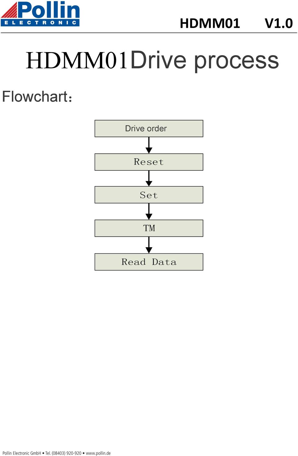
8 HDMM01Drive process Flowchart: Drive order
9 PACKAGE DRAWING

MMC314xMR. Ultra Small 3-axis Magnetic Sensor, With I 2 C Interface. Signal Path X. Signal Path Y. Signal Path Z FEATURES
 Ultra Small 3-axis Magnetic Sensor, With I 2 C Interface MMC314xMR FEATURES Full integration of 3-axis magnetic sensors and electronics circuits resulting in less external components needed Small Low profile
DS1621 Digital Thermometer and Thermostat
 Digital Thermometer and Thermostat www.dalsemi.com FEATURES Temperature measurements require no external components Measures temperatures from 55 C to +125 C in 0.5 C increments. Fahrenheit equivalent
DS1721 2-Wire Digital Thermometer and Thermostat
 www.dalsemi.com FEATURES Temperature measurements require no external components with ±1 C accuracy Measures temperatures from -55 C to +125 C; Fahrenheit equivalent is -67 F to +257 F Temperature resolution
FM75 Low-Voltage Two-Wire Digital Temperature Sensor with Thermal Alarm
 Low-Voltage Two-Wire Digital Temperature Sensor with Thermal Alarm Features User Configurable to 9, 10, 11 or 12-bit Resolution Precision Calibrated to ±1 C, 0 C to 100 C Typical Temperature Range: -40
DS1621 Digital Thermometer and Thermostat
 www.maxim-ic.com FEATURES Temperature measurements require no external components Measures temperatures from -55 C to +125 C in 0.5 C increments. Fahrenheit equivalent is -67 F to 257 F in 0.9 F increments
MicroMag3 3-Axis Magnetic Sensor Module
 1008121 R01 April 2005 MicroMag3 3-Axis Magnetic Sensor Module General Description The MicroMag3 is an integrated 3-axis magnetic field sensing module designed to aid in evaluation and prototyping of PNI
DS1307ZN. 64 x 8 Serial Real-Time Clock
 DS137 64 x 8 Serial Real-Time Clock www.maxim-ic.com FEATURES Real-time clock (RTC) counts seconds, minutes, hours, date of the month, month, day of the week, and year with leap-year compensation valid
NTE2053 Integrated Circuit 8 Bit MPU Compatible A/D Converter
 NTE2053 Integrated Circuit 8 Bit MPU Compatible A/D Converter Description: The NTE2053 is a CMOS 8 bit successive approximation Analog to Digital converter in a 20 Lead DIP type package which uses a differential
UV A Light Sensor with I 2 C Interface
 UV A Light Sensor with I 2 C Interface DESCRIPTION is an advanced ultraviolet (UV) light sensor with I 2 C protocol interface and designed by the CMOS process. It is easily operated via a simple I 2 C
LC898300XA. Functions Automatic adjustment to the individual resonance frequency Automatic brake function Initial drive frequency adjustment function
 Ordering number : A2053 CMOS LSI Linear Vibrator Driver IC http://onsemi.com Overview is a Linear Vibrator Driver IC for a haptics and a vibrator installed in mobile equipments. The best feature is it
YAS532B MS-3R Magnetic Field Sensor Type 3R
 MS-3R Magnetic Field Sensor Type 3R Overview The is a 3-axis geomagnetic sensor device with the following circuits integrated on one chip: a buffer amplifier, an AD converter, a clock generator circuit,
PACKAGE OUTLINE DALLAS DS2434 DS2434 GND. PR 35 PACKAGE See Mech. Drawings Section
 PRELIMINARY DS2434 Battery Identification Chip FEATURES Provides unique ID number to battery packs PACKAGE OUTLINE Eliminates thermistors by sensing battery temperature on chip DALLAS DS2434 1 2 3 256
7 OUT1 8 OUT2 9 OUT3 10 OUT4 11 OUT5 12 OUT6 13 OUT7 14 OUT8 15 OUT9 16 OUT10 17 OUT11 18 OUT12 19 OUT13 20 OUT14 21 OUT15 22 OUT16 OUT17 23 OUT18
 18 CHANNELS LED DRIVER GENERAL DESCRIPTION IS31FL3218 is comprised of 18 constant current channels each with independent PWM control, designed for driving LEDs. The output current of each channel can be
HP03 BAROMETER MODULE 2007-1-17 Version: 1.1
 . Integrated pressure sensor. Pressure Range 300-1100hpa. 16 Bit Σ Δ ADC. 11 coefficients for software compensation stored on chip. I 2 C Serial Interface. One system clock line (32768Hz). One hardware
The I2C Bus. NXP Semiconductors: UM10204 I2C-bus specification and user manual. 14.10.2010 HAW - Arduino 1
 The I2C Bus Introduction The I2C-bus is a de facto world standard that is now implemented in over 1000 different ICs manufactured by more than 50 companies. Additionally, the versatile I2C-bus is used
Cold-Junction-Compensated K-Thermocoupleto-Digital Converter (0 C to +1024 C)
") 19-2235; Rev 1; 3/02 Cold-Junction-Compensated K-Thermocoupleto-Digital General Description The performs cold-junction compensation and digitizes the signal from a type-k thermocouple. The data is output
19-2235; Rev 1; 3/02 Cold-Junction-Compensated K-Thermocoupleto-Digital General Description The performs cold-junction compensation and digitizes the signal from a type-k thermocouple. The data is output
MXD7202G/H/M/N. Low Cost, Low Noise ±2 g Dual Axis Accelerometer with Digital Outputs
 Low Cost, Low Noise ±2 g Dual Axis Accelerometer with Digital Outputs MXD7202G/H/M/N FEATURES Low cost Resolution better than 1 milli-g Dual axis accelerometer fabricated on a monolithic CMOS IC On chip
Data Acquisition Module with I2C interface «I2C-FLEXEL» User s Guide
 Data Acquisition Module with I2C interface «I2C-FLEXEL» User s Guide Sensors LCD Real Time Clock/ Calendar DC Motors Buzzer LED dimming Relay control I2C-FLEXEL PS2 Keyboards Servo Motors IR Remote Control
UVA and UVB Light Sensor with I 2 C Interface
 UVA and UVB Light Sensor with I 2 C Interface DESCRIPTION The senses UVA and UVB light and incorporates photodiode, amplifiers, and analog / digital circuits into a single chip using a CMOS process. When
DS18B20 Programmable Resolution 1-Wire Digital Thermometer
 www.dalsemi.com FEATURES Unique 1-Wire interface requires only one port pin for communication Multidrop capability simplifies distributed temperature sensing applications Requires no external components
The FT6x06 series ICs include FT6206 /FT6306, the difference of their specifications will be listed individually in this datasheet.
 FT6x06 Self-Capacitive Touch Panel Controller INTRODUCTION The FT6x06 Series ICs are single-chip capacitive touch panel controller ICs with a built-in 8 bit enhanced Micro-controller unit (MCU).They adopt
DATA SHEET. TDA1543 Dual 16-bit DAC (economy version) (I 2 S input format) INTEGRATED CIRCUITS
 (I 2 S input format) INTEGRATED CIRCUITS") INTEGRATED CIRCUITS DATA SHEET File under Integrated Circuits, IC01 February 1991 FEATURES Low distortion 16-bit dynamic range 4 oversampling possible Single 5 V power supply No external components required
INTEGRATED CIRCUITS DATA SHEET File under Integrated Circuits, IC01 February 1991 FEATURES Low distortion 16-bit dynamic range 4 oversampling possible Single 5 V power supply No external components required
INTEGRATED CIRCUITS DATA SHEET. PCF8591 8-bit A/D and D/A converter. Product specification Supersedes data of 2001 Dec 13.
 INTEGRATED CIRCUITS DATA SHEET Supersedes data of 2001 Dec 13 2003 Jan 27 CONTENTS 1 FEATURES 2 APPLICATIONS 3 GENERAL DESCRIPTION 4 ORDERING INFORMATION 5 BLOCK DIAGRAM 6 PINNING 7 FUNCTIONAL DESCRIPTION
Real Time Clock Module with I2C Bus
 Moisture Seitivity Level: MSL=1 FEATURES: With state-of-the-art RTC Technology by Micro Crystal AG RTC module with built-in crystal oscillating at 32.768 khz 3 timekeeping current at 3 Timekeeping down
EMERGING DISPLAY CUSTOMER ACCEPTANCE SPECIFICATIONS 20400 (LED TYPES) EXAMINED BY : FILE NO. CAS-10184 ISSUE : DEC.01,1999 TOTAL PAGE : 7 APPROVED BY:
 EXAMINED BY : FILE NO. CAS-10184 ISSUE : DEC.01,1999 TOTAL PAGE : 7 APPROVED BY:") EXAMINED BY : FILE NO. CAS-10184 APPROVED BY: EMERGING DISPLAY TECHNOLOGIES CORPORATION ISSUE : DEC.01,1999 TOTAL PAGE : 7 VERSION : 2 CUSTOMER ACCEPTANCE SPECIFICATIONS MODEL NO. : 20400 (LED TYPES) FOR
EXAMINED BY : FILE NO. CAS-10184 APPROVED BY: EMERGING DISPLAY TECHNOLOGIES CORPORATION ISSUE : DEC.01,1999 TOTAL PAGE : 7 VERSION : 2 CUSTOMER ACCEPTANCE SPECIFICATIONS MODEL NO. : 20400 (LED TYPES) FOR
BATRON. Specification for BTHQ 21605V-FSTF-I2C-COG
 BATRON Specification for BTHQ 21605V-FSTF-I2C-COG Version October 2003 PAGE 2 OF 12 DOCUMENT REVISION HISTORY 1: DOCUMENT REVISION FROM TO DATE DESCRIPTION CHANGED BY CHECKED BY A 2003.10.16 First release.
DIGITAL CONTROLLED STEREO AUDIO PROCESSOR WITH LOUDNESS. 100nF Recout(L) VOLUME + LOUDNESS VOLUME + LOUDNESS TDA7309 SUPPLY MUTE 12 AGND.
 VOLUME + LOUDNESS VOLUME + LOUDNESS TDA7309 SUPPLY MUTE 12 AGND.") DIGITAL CONTROLLED STEREO AUDIO PROCESSOR WITH LOUDNESS 1 FEATURES INPUT MULTIPLEXER: 3 STEREO INPUTS RECORD OUTPUT FUNCTION LOUDNESS FUNCTION VOLUME CONTROL IN 1dB STEPS INDEPENDENT LEFT AND RIGHT VOLUME
DIGITAL CONTROLLED STEREO AUDIO PROCESSOR WITH LOUDNESS 1 FEATURES INPUT MULTIPLEXER: 3 STEREO INPUTS RECORD OUTPUT FUNCTION LOUDNESS FUNCTION VOLUME CONTROL IN 1dB STEPS INDEPENDENT LEFT AND RIGHT VOLUME
2-wire Serial EEPROM AT24C512
 Features Low-voltage and Standard-voltage Operation 5.0 (V CC = 4.5V to 5.5V). (V CC =.V to 5.5V). (V CC =.V to.v) Internally Organized 5,5 x -wire Serial Interface Schmitt Triggers, Filtered Inputs for
ADXL345-EP. 3-Axis, ±2 g/±4 g/±8 g/±16 g Digital Accelerometer. Enhanced Product FEATURES GENERAL DESCRIPTION ENHANCED PRODUCT FEATURES APPLICATIONS
 Enhanced Product 3-Axis, ±2 g/±4 g/±8 g/±16 g Digital Accelerometer FEATURES Ultralow power: as low as 23 µa in measurement mode and 0.1 µa in standby mode at VS = 2.5 V (typical) Power consumption scales
EMERGING DISPLAY CUSTOMER ACCEPTANCE SPECIFICATIONS 16400(LED TYPES) EXAMINED BY : FILE NO. CAS-10068 ISSUE : JAN.19,2000 TOTAL PAGE : 7 APPROVED BY:
 EXAMINED BY : FILE NO. CAS-10068 ISSUE : JAN.19,2000 TOTAL PAGE : 7 APPROVED BY:") EXAMINED BY : FILE NO. CAS-10068 APPROVED BY: EMERGING DISPLAY TECHNOLOGIES CORPORATION ISSUE : JAN.19,2000 TOTAL PAGE : 7 VERSION : 3 CUSTOMER ACCEPTANCE SPECIFICATIONS MODEL NO. : 16400(LED TYPES) FOR
EXAMINED BY : FILE NO. CAS-10068 APPROVED BY: EMERGING DISPLAY TECHNOLOGIES CORPORATION ISSUE : JAN.19,2000 TOTAL PAGE : 7 VERSION : 3 CUSTOMER ACCEPTANCE SPECIFICATIONS MODEL NO. : 16400(LED TYPES) FOR
MODULE BOUSSOLE ÉLECTRONIQUE CMPS03 Référence : 0660-3
 MODULE BOUSSOLE ÉLECTRONIQUE CMPS03 Référence : 0660-3 CMPS03 Magnetic Compass. Voltage : 5v only required Current : 20mA Typ. Resolution : 0.1 Degree Accuracy : 3-4 degrees approx. after calibration Output
DS1821 Programmable Digital Thermostat and Thermometer
 ma www.maxim-ic.com FEATURES Requires no external components Unique 1-Wire interface requires only one port pin for communication Operates over a -55 C to +125 C (67 F to +257 F) temperature range Functions
24-Bit Analog-to-Digital Converter (ADC) for Weigh Scales FEATURES S8550 VFB. Analog Supply Regulator. Input MUX. 24-bit Σ ADC. PGA Gain = 32, 64, 128
 for Weigh Scales FEATURES S8550 VFB. Analog Supply Regulator. Input MUX. 24-bit Σ ADC. PGA Gain = 32, 64, 128") 24-Bit Analog-to-Digital Converter (ADC) for Weigh Scales DESCRIPTION Based on Avia Semiconductor s patented technology, HX711 is a precision 24-bit analogto-digital converter (ADC) designed for weigh
24-Bit Analog-to-Digital Converter (ADC) for Weigh Scales DESCRIPTION Based on Avia Semiconductor s patented technology, HX711 is a precision 24-bit analogto-digital converter (ADC) designed for weigh
TDA7448 6 CHANNEL VOLUME CONTROLLER 1 FEATURES 2 DESCRIPTION. Figure 1. Package
 6 CHANNEL CONTROLLER FEATURES 6 CHANNEL INPUTS 6 CHANNEL OUTPUTS ATTENUATION RANGE OF 0 TO -79dB CONTROL IN.0dB STEPS 6 CHANNEL INDEPENDENT CONTROL ALL FUNCTION ARE PROGRAMMABLE VIA SERIAL BUS DESCRIPTION
LM75 Digital Temperature Sensor and Thermal Watchdog with Two-Wire Interface
 Digital Temperature Sensor and Thermal Watchdog with Two-Wire Interface General Description The LM75 is a temperature sensor, Delta-Sigma analog-todigital converter, and digital over-temperature detector
ICS379. Quad PLL with VCXO Quick Turn Clock. Description. Features. Block Diagram
 Quad PLL with VCXO Quick Turn Clock Description The ICS379 QTClock TM generates up to 9 high quality, high frequency clock outputs including a reference from a low frequency pullable crystal. It is designed
Low-Jitter I 2 C/SPI Programmable Dual CMOS Oscillator
 eet General Description The DSC2111 and series of programmable, highperformance dual CMOS oscillators utilizes a proven silicon MEMS technology to provide excellent jitter and stability while incorporating
COMPLEMENTARY OUTPUT HALL EFFECT LATCH General Description. Features. Applications
 General Description The is an integrated Hall sensor with output driver designed for electronic commutation of brushless DC motor applications. The device includes an onchip Hall sensor for magnetic sensing,
TLI4946. Datasheet TLI4946K, TLI4946-2K, TLI4946-2L. Sense and Control. May 2009
 May 2009 TLI4946 High Precision Hall Effect Latches for Industrial and Consumer Applications TLI4946K, TLI4946-2K, TLI4946-2L Datasheet Rev. 1.0 Sense and Control Edition 2009-05-04 Published by Infineon
Ref Parameters Symbol Conditions Min Typ Max Units. Standby 3.5 10 μa. 3 Range 50 115 kpa. 4 Resolution 0.15 kpa. 5 Accuracy -20ºC to 85ºC ±1 kpa
 Freescale Semiconductor Miniature I 2 C Digital Barometer The is an absolute pressure sensor with digital output for low cost applications. A miniature 5 x 3 x 1.2 mm LGA package ideally suits it for portable
NHD-0420D3Z-FL-GBW-V3
 NHD-0420D3Z-FL-GBW-V3 Serial Liquid Crystal Display Module NHD- Newhaven Display 0420-4 Lines x 20 Characters D3Z- Model F- Transflective L- Yellow/Green LED Backlight G- STN-Gray B- 6:00 Optimal View
EMERGING DISPLAY CUSTOMER ACCEPTANCE SPECIFICATIONS 16290(LED TYPES) EXAMINED BY : FILE NO. CAS-10251 ISSUE : JUL.03,2001 TOTAL PAGE : 7
 EXAMINED BY : FILE NO. CAS-10251 ISSUE : JUL.03,2001 TOTAL PAGE : 7") EXAMINED BY : FILE NO. CAS-10251 EMERGING DISPLAY ISSUE : JUL.03,2001 APPROVED BY: TECHNOLOGIES CORPORATION TOTAL PAGE : 7 VERSION : 1 CUSTOMER ACCEPTANCE SPECIFICATIONS MODEL NO. : 16290(LED TYPES) FOR
EXAMINED BY : FILE NO. CAS-10251 EMERGING DISPLAY ISSUE : JUL.03,2001 APPROVED BY: TECHNOLOGIES CORPORATION TOTAL PAGE : 7 VERSION : 1 CUSTOMER ACCEPTANCE SPECIFICATIONS MODEL NO. : 16290(LED TYPES) FOR
Newhaven Display International, Inc. 2661 Galvin Ct. Elgin IL, 60124 Ph: 847-844-8795 Fax: 847-844-8796
 NHD-1.69-128160ASC3 Graphic Color OLED Display Module NHD- Newhaven Display 1.69-1.69 Diagonal Size 160128-160 x 128 Pixels AS- Model C- Full Color 3- +3.3V Power Supply Newhaven Display International,
FUNCTIONAL BLOCK DIAGRAM SDA SCL SMBALERT. SMBus SERIAL BUS INTERFACE ADDRESS SELECTION PWM CONFIG AUTOMATIC FAN SPEED CONTROL REGISTERS
 Data Sheet Temperature Sensor Hub and Fan Controller FEATURES Monitors up to 10 remote temperature sensors Monitors and controls speed of up to 4 fans independently PWM outputs drive each fan under software
GT Sensors Precision Gear Tooth and Encoder Sensors
 GT Sensors Precision Gear Tooth and Encoder Sensors NVE s GT Sensor products are based on a Low Hysteresis GMR sensor material and are designed for use in industrial speed applications where magnetic detection
Evaluating AC Current Sensor Options for Power Delivery Systems
 Evaluating AC Current Sensor Options for Power Delivery Systems State-of-the-art isolated ac current sensors based on CMOS technology can increase efficiency, performance and reliability compared to legacy
AS2815. 1.5A Low Dropout Voltage Regulator Adjustable & Fixed Output, Fast Response
 1.5A Low Dropout oltage Regulator Adjustable & Fixed Output, Fast Response FEATURES Adjustable Output Down To 1.2 Fixed Output oltages 1.5, 2.5, 3.3, 5.0 Output Current of 1.5A Low Dropout oltage 1.1 Typ.
3-Axis Digital Compass IC HMC5883L
 3-Axis Digital Compass IC HMC5883L Advanced Information The Honeywell HMC5883L is a surface-mount, multi-chip module designed for low-field magnetic sensing with a digital interface for applications such
Adding Heart to Your Technology
 RMCM-01 Heart Rate Receiver Component Product code #: 39025074 KEY FEATURES High Filtering Unit Designed to work well on constant noise fields SMD component: To be installed as a standard component to
SFP-TX 1000BASE-T SFP Transceiver 10/100/1000M SFP Transceiver
 Product Features Up to 1.25Gb/s bi-directional data links SFP form with compact RJ-45 connector +3.3V single power supply 0 to 70 o C operating case temperature Intelligent Auto-Negotiation support for
NHD C0220BiZ FSW FBW 3V3M
 NHD C0220BiZ FSW FBW 3V3M COG (Chip On Glass) Character Liquid Crystal Display Module NHD Newhaven Display C0220 COG, 2 Lines x 20 Characters BiZ Model, I 2 C interface F Transflective SW Side White LED
ADS9850 Signal Generator Module
 1. Introduction ADS9850 Signal Generator Module This module described here is based on ADS9850, a CMOS, 125MHz, and Complete DDS Synthesizer. The AD9850 is a highly integrated device that uses advanced
Tire pressure monitoring
 Application Note AN601 Tire pressure monitoring 1 Purpose This document is intended to give hints on how to use the Intersema pressure sensors in a low cost tire pressure monitoring system (TPMS). 2 Introduction
DDR SDRAM SODIMM. MT8VDDT3264H 256MB 1 MT8VDDT6464H 512MB For component data sheets, refer to Micron s Web site: www.micron.com
 SODIMM MT8VDDT3264H 256MB 1 MT8VDDT6464H 512MB For component data sheets, refer to Micron s Web site: www.micron.com 256MB, 512MB (x64, SR) 200-Pin SODIMM Features Features 200-pin, small-outline dual
64 x 8, Serial, I 2 C Real-Time Clock
 DS1307 64 x 8, Serial, I 2 C Real-Time Clock GENERAL DESCRIPTION The DS1307 serial real-time clock (RTC) is a lowpower, full binary-coded decimal (BCD) clock/calendar plus 56 bytes of NV SRAM. Address
10Gbps XFP Bi-Directional Transceiver, 10km Reach 1270/1330nm TX / 1330/1270 nm RX
 Features 10Gbps XFP Bi-Directional Transceiver, 10km Reach 1270/1330nm TX / 1330/1270 nm RX Supports 9.95Gb/s to 10.5Gb/s bit rates Hot-pluggable XFP footprint Maximum link length of 10km with SMF 1270/1330nm
Spread Spectrum Clock Generator
 Spread Spectrum Clock Generator DESCRIPTION is a clock generator for EMI (Electro Magnetic Interference) reduction. The peak of unnecessary (EMI) can be attenuated by making the oscillation frequency slightly
DTSB35(53)12L-CD20 RoHS Compliant 1.25G 1310/1550nm(1550/1310nm) 20KM Transceiver
12L-CD20 RoHS Compliant 1.25G 1310/1550nm(1550/1310nm) 20KM Transceiver") 产 品 规 格 书 Product Specification Sheet DTSB35(53)12L-CD20 RoHS Compliant 1.25G 1310/1550nm(1550/1310nm) 20KM Transceiver PRODUCT FEATURES Up to 1.25Gb/s data links FP laser transmitter for DTSB35(53)12L-CD20
产 品 规 格 书 Product Specification Sheet DTSB35(53)12L-CD20 RoHS Compliant 1.25G 1310/1550nm(1550/1310nm) 20KM Transceiver PRODUCT FEATURES Up to 1.25Gb/s data links FP laser transmitter for DTSB35(53)12L-CD20
DDR2 SDRAM FBDIMM MT36HTF25672F 2GB MT36HTF51272F 4GB. Features. 2GB, 4GB (x72, DR) 240-Pin DDR2 SDRAM FBDIMM. Features
 240-Pin DDR2 SDRAM FBDIMM. Features") SDRAM FBDIMM MT36HTF25672F 2GB MT36HTF51272F 4GB 2GB, 4GB (x72, DR) 240-Pin SDRAM FBDIMM Features Features 240-pin, fully buffered DIMM (FBDIMM) Fast data transfer rates: PC2-4200, PC2-5300, or PC2-6400
SDRAM FBDIMM MT36HTF25672F 2GB MT36HTF51272F 4GB 2GB, 4GB (x72, DR) 240-Pin SDRAM FBDIMM Features Features 240-pin, fully buffered DIMM (FBDIMM) Fast data transfer rates: PC2-4200, PC2-5300, or PC2-6400
SFP-SX with DOM 1.25Gb/s Multi-Mode SFP Transceiver 1000BASE-SX 1.0625Gb/s Fiber Channel
 Product Features Compliant to IEEE Std 802.3-2005 Gigabit Ethernet 1000Base-SX, with DOM Specifications according to SFF-8074i and SFF-8472, revision 9.5 Digital Diagnostic Monitoring 850nm Vertical Cavity
DDR2 SDRAM SODIMM MT8HTF3264HD 256MB MT8HTF6464HD 512MB MT8HTF12864HD 1GB For component data sheets, refer to Micron s Web site: www.micron.
 DDR2 SDRAM SODIMM MT8HTF3264HD 256MB MT8HTF6464HD 512MB MT8HTF12864HD 1GB For component data sheets, refer to Micron s Web site: www.micron.com 256MB, 512MB, 1GB (x64, DR): 200-Pin DDR2 SODIMM Features
Programmable Single-/Dual-/Triple- Tone Gong SAE 800
 Programmable Single-/Dual-/Triple- Tone Gong Preliminary Data SAE 800 Bipolar IC Features Supply voltage range 2.8 V to 18 V Few external components (no electrolytic capacitor) 1 tone, 2 tones, 3 tones
DIGITAL-TO-ANALOGUE AND ANALOGUE-TO-DIGITAL CONVERSION
 DIGITAL-TO-ANALOGUE AND ANALOGUE-TO-DIGITAL CONVERSION Introduction The outputs from sensors and communications receivers are analogue signals that have continuously varying amplitudes. In many systems
XFP Optical Receiver, 80km Reach
 Features Supports 9.95Gb/s to 11.1Gb/s bit rates Hot-pluggable XFP footprint Maximum link length of 80km with SMF APD ROSA receiver XFP MSA package with duplex LC connector No reference clock required
LC 2 MOS Signal Conditioning ADC with RTD Excitation Currents AD7711
 FEATURES Charge-Balancing ADC 24 Bits, No Missing Codes 0.0015% Nonlinearity 2-Channel Programmable Gain Front End Gains from 1 to 128 1 Differential Input 1 Single-Ended Input Low-Pass Filter with Programmable
DRM compatible RF Tuner Unit DRT1
 FEATURES DRM compatible RF Tuner Unit DRT1 High- Performance RF Tuner Frequency Range: 10 KHz to 30 MHz Input ICP3: +13,5dBm, typ. Noise Figure @ full gain: 14dB, typ. Receiver Factor: -0,5dB, typ. Input
DDR2 SDRAM SODIMM MT16HTF12864H 1GB MT16HTF25664H 2GB
 Features DDR2 SDRAM SODIMM MT16HTF12864H 1GB MT16HTF25664H 2GB For component data sheets, refer to Micron s Web site: www.micron.com Features 200-pin, small outline dual in-line memory module (SODIMM)
High Voltage Current Shunt Monitor AD8212
 High Voltage Current Shunt Monitor AD822 FEATURES Adjustable gain High common-mode voltage range 7 V to 65 V typical 7 V to >500 V with external pass transistor Current output Integrated 5 V series regulator
USB2.0 <=> I2C V4.4. Konverter Kabel und Box mit Galvanischetrennung
 USB2.0 I2C V4.4 Konverter Kabel und Box mit Galvanischetrennung USB 2.0 I2C Konverter Kabel V4.4 (Prod. Nr. #210) USB Modul: Nach USB Spezifikation 2.0 & 1.1 Unterstützt automatisch "handshake
MCP4017/18/19. 7-Bit Single I 2 C Digital POT with Volatile Memory in SC70. Package Types. Features. Device Features. Rheostat
 7-Bit Single I 2 C Digital POT with Volatile Memory in SC7 Features Potentiometer or Rheostat configuration options 7-bit: Resistor Network Resolution - 127 Resistors (128 Steps) Zero Scale to Full Scale
R EXT THERMISTOR. Maxim Integrated Products 1
 19-2219; Rev 0; 2/02 Thermistor-to-Digital Converter General Description The converts an external thermistor s temperature-dependent resistance directly into digital form. The thermistor and an external
TSL250, TSL251, TLS252 LIGHT-TO-VOLTAGE OPTICAL SENSORS
 TSL50, TSL5, TLS5 SOES004C AUGUST 99 REVISED NOVEMBER 995 Monolithic Silicon IC Containing Photodiode, Operational Amplifier, and Feedback Components Converts Light Intensity to Output Voltage High Irradiance
NT7606. STN LCDController/Driver. RAM-Map STN LCD Controller/Driver. Preliminary
 16C Characters X 3L Character X 3 Lines + 80 + icon 80 icons RAM-Map STN LCD Controller/Driver STN LCDController/Driver V0.04 V1.0 Preliminary Revision History...3 Features...4 General Description...4
DDR SDRAM SODIMM MT16VDDF6464H 512MB MT16VDDF12864H 1GB
 SODIMM MT16VDDF6464H 512MB MT16VDDF12864H 1GB 512MB, 1GB (x64, DR) 200-Pin DDR SODIMM Features For component data sheets, refer to Micron s Web site: www.micron.com Features 200-pin, small-outline dual
1-to-8 I 2 C Bus Switches/Multiplexers with Bus Lock-Up Detection, Isolation, and Notification
 19-4207; Rev 0; 9/08 EVALUATION KIT AVAILABLE 1-to-8 I 2 C Bus Switches/Multiplexers with Bus General Description The 8-channel I 2 C switches/multiplexers expand the main I 2 C bus to any combination
LCM NHD-12032BZ-FSW-GBW. User s Guide. (Liquid Crystal Display Graphic Module) RoHS Compliant. For product support, contact
 RoHS Compliant. For product support, contact") User s Guide -FSW-GBW LCM (Liquid Crystal Display Graphic Module) RoHS Compliant NHD- 12032- BZ- F - SW- G- B- W- Newhaven Display 120 x 32 pixels Version Line Transflective Side White LED B/L STN- Gray
User s Guide -FSW-GBW LCM (Liquid Crystal Display Graphic Module) RoHS Compliant NHD- 12032- BZ- F - SW- G- B- W- Newhaven Display 120 x 32 pixels Version Line Transflective Side White LED B/L STN- Gray
Process modules Digital input PMI for 24 V DC inputs for 120 V AC inputs
 E031026 000823 Process modules Digital input PMI for inputs for 120 V AC inputs PMI Input E4, E5, GND L- PMI 120 V AC Input E4, E5, Common C E6, E7, GND L- E6, E7, Common C LEDs for the inputs operation
DDR2 SDRAM FBDIMM MT18HTF12872FD 1GB MT18HTF25672FD 2GB. Features. 1GB, 2GB (x72, DR) 240-Pin DDR2 SDRAM FBDIMM. Features
 240-Pin DDR2 SDRAM FBDIMM. Features") SDRAM FBDIMM MT18HTF12872FD 1GB MT18HTF25672FD 2GB 1GB, 2GB (x72, DR) 240-Pin SDRAM FBDIMM Features Features 240-pin, fully buffered dual in-line memory module (FBDIMM) Fast data transfer rates: PC2-4200,
SDRAM FBDIMM MT18HTF12872FD 1GB MT18HTF25672FD 2GB 1GB, 2GB (x72, DR) 240-Pin SDRAM FBDIMM Features Features 240-pin, fully buffered dual in-line memory module (FBDIMM) Fast data transfer rates: PC2-4200,
TSL213 64 1 INTEGRATED OPTO SENSOR
 TSL 64 INTEGRATED OPTO SENSOR SOES009A D4059, NOVEMBER 99 REVISED AUGUST 99 Contains 64-Bit Static Shift Register Contains Analog Buffer With Sample and Hold for Analog Output Over Full Clock Period Single-Supply
GDM1602A SPECIFICATIONS OF LCD MODULE. Features. Outline dimension
 SPECIFICATIONS OF LCD MODULE Features 1. 5x8 dots 2. Built-in controller (S6A0069 or Equivalent) 3. Power supply: Type 5V 4. 1/16 duty cycle 5. LED backlight 6. N.V. option Outline dimension Absolute maximum
155Mbps/1250Mbps SFP Bi-Directional Transceiver, 40km Reach 1310nm TX / 1550 nm RX
 Features 155Mbps/1250Mbps SFP Bi-Directional Transceiver, 40km Reach 1310nm TX / 1550 nm RX 1310nm FP laser and PIN photodetector for 40km transmission Compliant with SFP MSA and SFF-8472 with simplex
Product Datasheet P1110 915 MHz RF Powerharvester Receiver
 DESCRIPTION The Powercast P1110 Powerharvester receiver is an RF energy harvesting device that converts RF to DC. Housed in a compact SMD package, the P1110 receiver provides RF energy harvesting and power
Embedded Multi-Media Card Specification (e MMC 4.5)
") Product Features: Packaged NAND flash memory with e MMC 4.5 interface Compliant with e MMC Specification Ver 4.41 & 4.5. Bus mode - High-speed e MMC protocol - Provide variable clock frequencies
Product Features: Packaged NAND flash memory with e MMC 4.5 interface Compliant with e MMC Specification Ver 4.41 & 4.5. Bus mode - High-speed e MMC protocol - Provide variable clock frequencies
DDR SDRAM SODIMM. MT9VDDT1672H 128MB 1 MT9VDDT3272H 256MB MT9VDDT6472H 512MB For component data sheets, refer to Micron s Web site: www.micron.
 Features DDR SDRAM SODIMM MT9VDDT1672H 128MB 1 MT9VDDT3272H 256MB MT9VDDT6472H 512MB For component data sheets, refer to Micron s Web site: www.micron.com Features 200-pin, small-outline dual in-line memory
8-Bit Flash Microcontroller for Smart Cards. AT89SCXXXXA Summary. Features. Description. Complete datasheet available under NDA
 Features Compatible with MCS-51 products On-chip Flash Program Memory Endurance: 1,000 Write/Erase Cycles On-chip EEPROM Data Memory Endurance: 100,000 Write/Erase Cycles 512 x 8-bit RAM ISO 7816 I/O Port
PCT2075. 1. General description. I 2 C-bus Fm+, 1 degree C accuracy, digital temperature sensor and thermal watchdog
 I 2 C-bus Fm+, 1 degree C accuracy, digital temperature sensor and thermal watchdog Rev. 9 24 October 2014 Product data sheet 1. General description The is a temperature-to-digital converter featuring
ABRIDGED DATA SHEET EVALUATION KIT AVAILABLE
 EVALUATION KIT AVAILABLE General Description DeepCoverM embedded security solutions cloak sensitive data under multiple layers of advanced physical security to provide the most secure key storage possible.
NCP1840. 8-Channel Programmable LED Driver
 8-Channel Programmable LED Driver The NCP1840 is a general purpose LED driver that allows for full programmability of eight separate LED channels through a simple I 2 C serial communication interface.
Features. Dimensions
 Description With an IDE interface and strong data retention ability, 40-Pin IDE Flash Modules are ideal for use in the harsh environments where Industrial PCs, Set-Top Boxes, etc. are used. Placement Features
TRIPLE PLL FIELD PROG. SPREAD SPECTRUM CLOCK SYNTHESIZER. Features
 DATASHEET ICS280 Description The ICS280 field programmable spread spectrum clock synthesizer generates up to four high-quality, high-frequency clock outputs including multiple reference clocks from a low-frequency
DDR3 SDRAM UDIMM MT8JTF12864A 1GB MT8JTF25664A 2GB
 DDR3 SDRAM UDIMM MT8JTF12864A 1GB MT8JTF25664A 2GB 1GB, 2GB (x64, SR) 240-Pin DDR3 SDRAM UDIMM Features For component data sheets, refer to Micron s Web site: www.micron.com Features DDR3 functionality
HCC4541B HCF4541B PROGRAMMABLE TIMER
 HCC4541B HCF4541B PROGRAMMABLE TIMER 16 STAGE BINARI COUNTER LOW SYMMETRICAL OUTPUT RESISTANCE, TYPICALLY 100 OHM AT DD = 15 OSCILLATOR FREQUENCY RANGE : DC TO 100kHz AUTO OR MASTER RESET DISABLES OSCIL-
2.488Gbps Compact Bi-Di SFP Transceiver, 20km Reach 1490nm TX / 1310 nm RX
 2.488Gbps Compact Bi-Di SFP Transceiver, 20km Reach 1490nm TX / 1310 nm RX Features Support 2.488Gbps data links 1490nm DFB laser and PIN photodetector for 20km transmission 2xBi-directional transceivers
1.55V DDR2 SDRAM FBDIMM
 1.55V DDR2 SDRAM FBDIMM MT18RTF25672FDZ 2GB 2GB (x72, DR) 240-Pin DDR2 SDRAM FBDIMM Features Features 240-pin, fully buffered DIMM (FBDIMM) Very low-power DDR2 operation Component configuration: 256 Meg
NB3H5150 I2C Programming Guide. I2C/SMBus Custom Configuration Application Note
 NB3H550 I2C Programming Guide I2C/SMBus Custom Configuration Application Note 3/4/206 Table of Contents Introduction... 3 Overview Process of Configuring NB3H550 via I2C/SMBus... 3 Standard I2C Communication
Section 3. Sensor to ADC Design Example
 Section 3 Sensor to ADC Design Example 3-1 This section describes the design of a sensor to ADC system. The sensor measures temperature, and the measurement is interfaced into an ADC selected by the systems
LTC1390 8-Channel Analog Multiplexer with Serial Interface U DESCRIPTIO
 FEATRES -Wire Serial Digital Interface Data Retransmission Allows Series Connection with Serial A/D Converters Single V to ±V Supply Operation Analog Inputs May Extend to Supply Rails Low Charge Injection
24-Bit ANALOG-TO-DIGITAL CONVERTER
 ADS1211 ADS1211 ADS1211 ADS1210 ADS1210 ADS1210 ADS1211 JANUARY 1996 REVISED SEPTEMBER 2005 24-Bit ANALOG-TO-DIGITAL CONVERTER FEATURES DELTA-SIGMA A/D CONVERTER 23 BITS EFFECTIVE RESOLUTION AT 10Hz AND