Optical Access Networks
|
|
|
- Candace Long
- 7 years ago
- Views:
Transcription
1 Access Networks and Full Service Providers Architectures and Classification of Access Networks Alternative Access Technologies Fibre Access Networks: FTTCab, FTTC/B, FTTB/H PON Architectures: AF, TPON, WPON, WRPON APON/BPON, EPON and GPON Future Developments -1-

2 Access Networks and Full Service Providers The networks feeding the metro (and core) networks by gathering data from the end users (us). The two main contenders are CATV companies and phone companies. This is due to the two existing network infrastructures: Telephone (POTS) networks (xdsl); Cable TV networks (Cable Modems). Since existing cable infrastructures are available, operators try to milk their networks to provide data services such as high speed Internet access. This requires upgrading those infrastructures, to overcome the 4 khz limited unidirectional broadcast. Services can be switched/broadcast, symmetrical/asymmetrical, unidirectional/bidirectional, and can be provided with different bandwidths. -2-

3 Services Supported by Access Networks Service Type Downstream Bandwidth Upstream Bandwidth Telephony Switched 4 khz 4 khz ISDN Switched 144 kbit/s 144 kbit/s Video Broadcasting Broadcast 6 MHz or 2 to 6 Mbit/s 0 Interactive Video Switched 6 Mbit/s Small Internet Access Switched Some Mbit/s Small (initially) Video-Conference Switched 6 Mbit/s 6 Mbit/s Enterprise Services Switched 1.5 Mbit/s to 10 Gbit/s 1.5 Mbit/s to 10 Gbit/s Downstream: from the service provider to the user. Upstream: from the user to the service provider. Full Service: provision of all the services available through access networks. Criteria for Classification of Services Bandwidth requirements. Symmetrical (bidirectional) or Asymmetrical (unidirectional). Broadcast or Switched. -3-

4 Architectures for Access Networks H = Hub RN = Remote Node NIU = Network Interface Unit RN NIU A NIU may be located in the premises of one subscriber or may serve several subscribers. H RN NIU The Hub is usually part of a larger network, but may be considered as the source of data for the NIUs and the destination for data coming from the NIUs. Different combinations of services and network topologies are possible: a broadcast service may be supported by a broadcast or switched network, as well as a switched service. In a broadcast network, a RN broadcasts data it receives from the Hub to all its NIUS. In a switched network, a RN processes the data coming from the Hub and, eventually, sends different traffic flows to each of its NIUs. RN Fe eder Network Dis tribution Network NIU -4-

5 Classification of Access Networks Distribution Feeder Network Network Broadcast Switched Shared BW CATV (HFC), TPON Dedicated BW WPON Telephony, DSL, WRPON HFC = Hybrid Fiber Coaxial; DSL : Digital Subscriber Loop; PON : Passive Optical Network; T = Telephony; W : Wavelength; WR = Wavelength Routed; BW = BandWidth. Broadcast networks may be cheaper than switched ones, are adequate for provision of broadcast services, and have the advantage of identical NIUs for all the subscribers. Switched Networks are more appropriate for switched services and provide more security. Fault localization is generally easier in switched networks, because intelligence is in the network instead of the NIUs, as in broadcast networks. In switched networks the NIUs may be simpler than in broadcast networks. A disadvantage of feeder networks with shared bandwidth is the need for each NIU to operate in the total network bandwidth. Besides, with dedicated bandwidth it is possible to provide QoS guaranties to the NIUs. -5-

6 Local Telephone Network CO = Central Office (USA) or Local Exchange (EU) TPs = Twisted Pairs (copper) This is a switched network designed to provide a bandwidth of 4 khz to each subscriber, although modulation and signal processing techniques available nowadays enable the use of much larger bandwidths. The same infrastructure is used by the ISDN (BW of 144 kbit/s) and by DSL technology (a few Mbit/s). With the latter, the possible data rate varies inversely with the distance to the local exchange, and the 4 khz filters of the original telephone line must be removed

7 CATV Network HFC Architecture A better designation to describe the HFC architecture would be: SMFCB = Subcarrier Modulated Fibre Coaxial Bus Distribution Network Feeder Network HE Optical Fibre RN Coaxial Cable HE = Head End Amplifier Tap The feeder network uses the signal of a laser with SCM (Sub Carrier Multiplexing). The feeder network uses a bandwidth between 50 and 550 MHz. In this band, the coaxial cable can carry about 70 TV signals in AM-VSB. A spectral window between 5 and 40 MHz is also available, for return signals. -7-

8 Alternative (broadband) Access Technologies Satellite Systems Systems for direct broadcasting by satellite (DBS) use geostationary satellites to broadcast a few hundred TV channels, and may provide larger bandwidth than cable broadcasting systems, but frequency reuse is limited due the large coverage area (footprint) of each satellite, and it is not easy to provide support for upstream traffic. Fixed Wireless Access (FWA) Although with limited BW and reach, these systems may be deployed quickly and enable new service providers to enter the market without a cable infrastructure. The more relevant alternatives are MMDS (Multichannel Multipoint Distribution System) and LMDS (Local Multipoint Distribution System). Both are line of sight systems. MMDS provides more than 30 TV channels in the bandwidth from 2 to 3 GHz, with a reach of 15 to 55 km, depending on the transmitted power. LMDS operates in the 28 GHz band with a bandwidth of 1.3 GHz, and is more adequate for short reach coverage (3 to 5 km, depending on rain) in dense urban areas. Free Space Optics (Optical Wireless) These systems employ lasers, and may provide a transmission capacity from about 100 Mbit/s up to 2.5 Gbit/s, with a reach from hundreds of m to a few km, in line of sight
 and LMDS (Local Multipoint Distribution System). Both are line of sight systems.")
9 Enhanced HFC (EHFC) Architecture Upstream Downstream Video Available for downstream traffic Frequency (MHz) Improvements provided by the EHFC Architecture The bandwidth may be increased up to 1 GHz. Systems using 862 MHz are already available. In each channel, digital modulation techniques with high spectral efficiency may be used, such as 256-QAM (7 (bit/s)/hz). The fibre may penetrate deeper into the network, thereby reducing the number of subscribers served by each RN to about 50 (instead of 500, typical of the HFC architecture). Multiple fibres and multiple wavelengths may be used (greater capacity). Besides high power lasers combined with booster optical amplifiers in the wavelength of 1.55 µm, signals in the 1.3 µm window may be multiplexed in narrow band mode (narrowcasting), for selected groups of users. Functions of the NIUs Each NIU may serve one or more subscribers, and its functions are: (1) to decompose the signals into telephone and video signals, and (2) send them on twisted and coaxial pairs, respectively, to each subscriber. -9-
.")
10 Fibre Access Networks: FTTCab, FTTC/B, FTTB/H In contrast with the HFC architecture, in fibre access networks (Fiber In The Loop, FITL) data are transmitted in digital format over optical fibre, in the distribution network, until fibre terminating nodes designated by s = Optical Network Units The designations used to describe this architecture depend on the proximity between the s and the subscribers' premises: FTTH (Fiber To The Home); s perform the functions of NIUs; FTTC (Fiber To The Curb) / FTTB (Fiber To The Building); the s serve a small number of subscribers (8 to 64); typically, the fibre is terminated at less than 100 m from the subscriber, and there is an additional copper distribution network between s and NIUs; FTTCab (Fiber To The Cabinet); the fibre is terminated in a nearby cabinet, less than 1 km from the subscriber, and a distribution network between s and NIUs is also employed. Central Office Cabinet Curb Home CO RN NIU FTTCab CO Fiber Fiber Copper RN NIU FTTC/FTTB CO RN /NIU FTTB/FTTH Passive Optical Network (PON) FTTP : Fiber To The Premises -10-
; the fibre is")
11 PON Architectures PON = Passive Optical Network : network between the CO and the. The remote node (RN) is a simple passive device, such as an optical star coupler or a static wavelength router, and sometimes may be installed at the central office. The designation FTTC is commonly used to describe an architecture in which the signals are broadcast from the CO to the s, and the s share the total bandwidth in TDM. This architecture is also designated by BMFCB (Baseband Modulated Fiber Coaxial Bus) or SDV (Switched Digital Video). In the context of FTTC architectures, the feeder network is the part of the network between the CO and the RNs, and the distribution network is the part between the RNs and the s. Several types of architectures may be realized by employing different types of sources at the CO, combined with different types of RNs. Architecture Shared Fiber Power Splitting Data Rate at the Node Synchronization Shared CO AF (All Fiber) No None 1 No No TPON Yes 1/N N Yes Yes WPON Yes 1/N 1 Yes No WRPON Yes None N : number of s in the network. Data Rate: 1 means that operates at the rate of the traffic delivered to it, instead of the aggregate rate N. 1 Yes Yes -11-
 or SDV (Switched Digital Video).")
12 AF (All Fiber) Architectures Solution with point-to-point fibre Solution with fibre in a ring CO CO cable The simplest PON architecture uses a pair of fibres between the CO and each. Physically, the fibres may be deployed in a ring configuration. Instead of a pair, a single fibre with bidirectional transmission may be used, but the same wavelength cannot be used to simultaneously transmit in both directions, due to reflections at the ends. The solution is to use Time Division Duplex (TDD) or different wavelengths, (1.3 and 1.55 µm, for example), which may be called Wavelength Division Duplex (WDD).. The cost of this solution grows linearly with the number of s, and the operator must deploy and maintain all the fibres. Presently, this architecture is used in small scale, mainly to provide high speed services to enterprises (NTT, in Japan, operates a system with data rates between 8 and 32 Mbit/s in each fibre). In the SONET/SDH rings, a pair of fibres is shared by multiple s (which are OADMs). These rings are considered as an alternative access solution, but not as members of the PON family. -12-
 or different wavelengths, (1.3 and 1.55 µm, for example), which may be called Wavelength Division Duplex (WDD).")
13 TPON (Telephony PON) Architecture In spite of being a broadcast architecture, it may support switched services by assigning specific time slots to each, based on its bandwidth needs. In the distribution network, the upstream shares the fibre with the downstream by using TDM, in a different wavelength, through a coupler. s must be synchronized (ranging). Rx: pin FET Tx: LED or FP laser The number of s that can be supported is limited by the splitting losses at the RN. CO Laser 1,55 µm Passive Star Coupler s must operate at the aggregate rate coming from the CO. There is a trade off between transmitted power, receiver sensitivity, data rate, number of s, and maximum coverage distance. RN Splitter/ Combiner MUX/DX 1310/1550 nm MUX/DX 1310/1550 nm MUX/DX 1310/1550 nm Laser 1,3 µm Laser 1,3 µm Laser 1,3 µm -13-

14 Commercial Opportunity for PONs Presently, the higher data rates in the deployed access networks are offered by xdsl technologies and Cable MODEMs, and they do not usually reach more than 1.5 Mbit/s. Contrasting with this, the bandwidth grows dramatically in the transport network due to the adoption of WDM technology, which is already penetrating into metropolitan networks (MANs). Simultaneously, most organizational LANs have been upgraded from 10 do 100 Mbit/s, and it is expectable that they will be upgraded to gigabit-ethernet in the near future. The result of these conditions is an ever larger gap between the capacity of metropolitan networks and the needs of residential subscribers and SMEs (Small and Medium Enterprises). PONs may fill this gap, satisfying the market needs in the interval of data rates from 1.5 Mbit/s to 155 Mbit/s, not yet supported by economical alternative technologies. -14-
.")
15 PON Typical Architecture A PON is formed by and Optical Line Terminal (OLT), located at the CO, and a set of s located at or in the neighbourwood of subscribers' premises. Between these active elements an ODN (Optical Distribution Network) is deployed, employing optical fibres and passive components (splitters/combiners and couplers). Presently, the ODN may operate at 155 Mbit/s, 622 Mbit/s, 1.25 Gbit/s, or 2.5 Gbit/s, by using one of the available standards APON/BPON/EPON/GPON. Downstream traffic is broadcast by the OLT to all s. Each of these processes the traffic which is destined to it, through an address contained in the header of the PDU (Protocol Data Unit). Upstream traffic uses TDMA, under control of the OLT located at the CO, which assigns time slots to each for synchronized transmission of its data bursts. The bandwidth assigned to each user may be static or dynamically variable, for support of voice, data and video applications. -15-
.")
16 FSAN (Full Service Access Network) Standard This standard was developed by an alliance of service providers and equipment builders, and specifies a TPON architecture based on ATM (APON) with a downstream bandwidth of up to 622 Mbit/s and an upstream bandwidth of up to 155 Mbit/s. Maximum coverage distance is 20 km, with a total fibre attenuation between 10 and 30 db. Practical values of the link power budget allow power splitting by 16 or 32 at the RN. For example, an APON operating at 622 Mbit/s with a 32-way splitter may provide a data rate of 20 Mbit/s to each subscriber. An APON may operate over a single fibre, by using different wavelengths in the upstream (1.3 µm) and downstream (1.55 µm), or over a pair of fibres, by employing only 1.3 µm transmitters

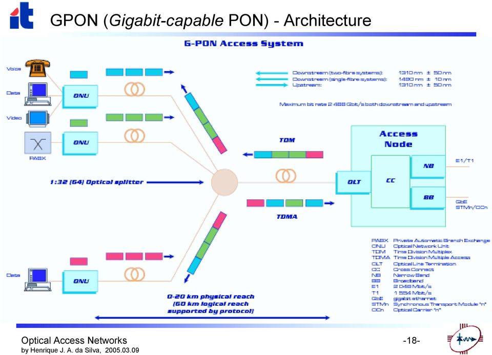
17 BPON (Broadband PON) and GPON (Gigabit-capable PON) APONs (ATM-based PONs) were developed during the second half of the 1990 decade, through the FSAN (Full Service Access Network) initiative, which resulted from the industrial alliance promoted by BT in 1995 with the objective of developing standards to extend high speed services (such as data over IP, video and Ethernet 10/100) over fibre to residential customers and SMEs. The APON standard was primarily focused in applications for SMEs, and its initial version did not include provision of video services over the PON. The APON format developed by the FSAN alliance was used as the basis for an international standard released by ITU-TS (Rec. G.893), designated by BPON (Broadband PON). This standard supports more broadband services, including high-speed Ethernet and video distribution. In 2001, the FSAN group initiated the development of the standard GPON (Gigabit-capable PON, Rec. G.984, ITU-T, 2003), for full service support, including voice (TDM, over SONET/SDH), Ethernet (10/100 BaseT), ATM, leased lines, wireless extension, etc., by using a convergence protocol layer designated GFP (Generic Framing Procedure). The main characteristics of the GPON standard are: Physical reach of at least 20 km, with support for logical reach up to 60 km; Support of several data rate options, using the same protocol, including a symmetrical link at 622 Mbit/s or 1.25 Gbit/s, or 2.5 Gbit/s downstream with 1.25 Gbit/s upstream. Management of end-to-end services with good capabilities of OAM&P (Operation, Administration, Maintenance and Provisioning). Security of downstream traffic at protocol level, due to the multicast nature of the PON. -17-
, designated by BPON (Broadband PON).")
 - Architecture")
18 GPON (Gigabit-capable PON) - Architecture -18-
19 EPON (Ethernet PON) When it was developed, the APON standard was not the more appropriate solution for local access in large scale, because it did not include the capability to transport video. On the other hand, evolution of LANs to gigabit Ethernet and 10-gigabit Ethernet is a strong motivation to eliminate the need of conversion between IP and ATM protocols, in the interconnection of LANs to WANs (Wide Area Networks). In November 2000, a group of manufacturers of Ethernet equipment initiated the development of an Ethernet PON (EPON) standard under an agreement with the IEEE, with the creation of the the EFM (Ethernet in the First Mile) study group in Although the EPON concept provides larger bandwidth, lower costs, and wider service capabilities than the APON standard, the network architecture is similar and the EPON standard complies to many specifications included in recommendations G.983/4 of ITU-T. The IEEE standard for Ethernet in the first mile is 802.3ah. -19-
 standard under an agreement with the IEEE, with the creation of the the EFM")
20 WPON (WDM PON) Architecture This architecture enables the operation of each at the data rate of the traffic delivered to it, instead of the aggregate data rate transmitted by the CO. Filter 1 However, it is still limited by the power splitting at the star coupler (RN).,,..., 1 2 N 1.55 µm band Laser 1.3 µm Tx at the CO: Array of Lasers or Tuneable Laser CO WDM Laser RN Splitter/ Combiner Filter 2 Laser 1.3 µm s share the upstream wavelength of 1.3 µm, with TDM.,,..., 1 2 N 1.55 µm band Filter N Laser 1.3 µm -20-

21 WRPON Architecture The introduction of static wavelength routing solves the splitting loss problem, maintaining all the advantages of the WPON. 1 Besides, it allows provision of point-to-point dedicated services. 1, 2,..., N 1.3 or 1.55 µm band Laser 1.3 µm The AWG (Arrayed Waveguide Grating) operates as a static wavelength router. CO WDM Laser RN AWG Combiner 2 Laser 1.3 µm The first system demonstrated (PPL: Passive Photonics Loop) used 16 channels in the 1.3 µm band, for downstream traffic, and 16 additional channels in the 1.55 µm band, for upstream transmission. This architecture is not economical, because it needs two expensive lasers for each (including the one in the CO). N Laser 1.3 µm -21-
22 RITENET WRPON Architecture Each frame transmitted by the CO includes a data field and a field for return traffic, during which the laser remains switched ON. Transmitted frame modulated signal (downstream) unmodulated signal 1 Coupler MODULATOR CO WDM Laser WDM,,..., 1 2 N 1.55 µm band RN AWG modulated signal (upstream) Coupler 2 MODULATOR This architecture avoids having a laser in each, replacing it by an optical modulator which reuses the signal received from the CO. N Coupler If a single receiver is used at the CO, the s must use TDM to access it. MODULATOR -22-
23 LARNET WRPON Architecture This is an economical alternative to RITENET that uses a LED instead of the modulator, in the s, for upstream transmission. The LED emits a broadband signal which spectrum is split into different wavelengths by the AWG, with a loss factor of at least 1/N (for N s). 1 LED 1.3 µm CO LED 1.55 µm 1,3 µm RN AWG 2 LED 1.3 µm A LED may also be used at the CO, in which case the signal emitted downstream is effectively broadcast to all s. It is possible to have two transmitters at the CO: a 1.3 µm LED, for example, broadcasting the signal to all s, and a 1.55 µm laser, transmitting only for selected s. This is an economical solution for broadcasting analog video signals without the need of an overlay dedicated network. N LED 1.3 µm -23-
24 Spectral Slicing The broadband signal emitted by the LED is sent through the AWG. Only the fraction of the spectrum corresponding to the channel pass band of the AWG comes out of each output. LED Power Wavelength data AWG Power Power Power 1 Wavelength 2 Wavelength N Wavelength -24-
25 Scenario for PON Evolution Grow As You Go Strategy An operator may follow a progressive upgrading sequence, from a simple TPON architecture towards one of the more complex WRPON architectures. This evolution may be realized with minimum disruption of existing services and without waste of installed equipment. The terminal equipment may be upgraded when new services and/or additional capacity are required, without any change in the deployed fibre network (grow as you go). Possible Evolution Scenario for a PON The operator installs a simple broadcast PON, which is a star network with bandwidth shared by the s. If it becomes necessary to support more s, the operator may upgrade the network to a WPON, which is a broadcast network with dedicated bandwidth provided to each. The transmitters at the CO must be replaced by WDM transmitters, maintaining the same s. If greater capacity per becomes necessary, the operator may upgrade the network to a WRPON, which is a switched network with dedicated bandwidth to each. The WRPON may also support broadcast services efficiently, by employing the spectral slicing technique. -25-
26 Future Developments Capacity Increase (in both GPON and EPON) Through combinations of TDM with WDM and, eventually, CDMA; cheaper components are required (probably Coarse WDM with polymer based AWGs and VCSEL arrays). Through increase of data rate, with faster lasers and more sensitive burst-mode receivers (with broadband SAGM APDs). QoS in EPON None of the currently existing EPON network access protocols is capable of supporting variable burst and delay sensitive multimedia streams and, in view of the increasing share of multimedia in the overall IP traffic, this inability represents a serious drawback and lack of future proof characteristics. There is a need for introducing future-proof QoS policies along with increased security measures to counteract any possible network intrusion and data theft. -26-
27 Bibliography Books Rajiv Ramaswami and Kumar N. Sivarajan, "Optical Networks A Practical Perspective" (second edition), Morgan Kaufmann Publishers, Academic Press, (Chapter 11) Denis J. G. Mestdagh, "Fundamentals of Multiaccess Optical Fiber Networks", Artech House, (Part II) Periodicals You may start with the IEEE Communications Magazine (the February 2005 issue includes two papers on EPON access protocols). -27-
28 END Thank You for your patience and attention. Please send your queries and comments to: -28-
Ethernet Passive Optical Networks EPON
 Ethernet Passive Optical Networks EPON IEEE 802.3 Ethernet in the First Mile Study Group January 8-9, 2001, Irvine, CA Gerry Pesavento Alloptic, Inc. Tel 925-245-7647 Email gerry.pesavento@alloptic.com
The Economics of Broadband Access Platform Evolution
 The Economics of Broadband Access Platform Evolution The EU's ACTS (Advanced Communications Technologies and Services) research programme has tested a number of approaches to delivering broadband services
Copyright. Transport networks. Physical layer Transport and access networks. Pag. 1
 Physical layer Transport and access networks Gruppo Reti TLC nome.cognome@polito.it http://www.telematica.polito.it/ COMPUTER NETWORK DESIGN Physical layer review - 1 Copyright Quest opera è protetta dalla
BroadbandSoHo. Verizon MDU FTTP Overview. Document Description:
 BroadbandSoHo Verizon MDU FTTP Overview Document Description: The enclosed document was created to give a basic overview of Verizon s FTTP PON, and technology terms behind there Fios product in regards
Passive Optical Networks: Recent Developments and Issues
 Passive Optical Networks: Recent Developments and Issues CTO and Co-Founder Nayna Networks, Inc. 180 Rose Orchard Way San Jose, CA 95134 USA www.nayna.com Raj Jain Adjunct Professor Ohio State University
Gigabit-capable Passive Optical Networks (GPON): General characteristics
: General characteristics") Gigabit-capable Passive Optical Networks (GPON): General characteristics SERIES G: TRANSMISSION SYSTEMS AND MEDIA, DIGITAL SYSTEMS AND NETWORKS Digital sections and digital line system Optical line systems
Gigabit-capable Passive Optical Networks (GPON): General characteristics SERIES G: TRANSMISSION SYSTEMS AND MEDIA, DIGITAL SYSTEMS AND NETWORKS Digital sections and digital line system Optical line systems
Introduction to Optical Networks
 Yatindra Nath Singh Assistant Professor Electrical Engineering Department Indian Institute of Technology, Kanpur Email: ynsingh@ieee.org http://home.iitk.ac.in/~ynsingh 1 What are optical network? Telecomm
Genexis FTTH Network Architecture
 Genexis FTTH Network Architecture An introduction to the Genexis FTTH Network Architecture This document contains general information about the Genexis FTTH Network Architecture. Contents 1. Introduction...2
XDSL and DSLAM Access Technologies
 XDSL and DSLAM Access Technologies Abstract What are the differences between the different forms of xdsl technology, such as ADSL and HDSL? How are they implemented. What are the limitations? What are
Operator s Requirements for G-PON:
 Operator s Requirements for G-PON: Summary Of Work In ITU-T SG15/Q2 GSR Brian Ford BellSouth BellSouth, British Telecom, Deutsche Telekom, France Telecom, NTT, Telecom Italia and SBC Introduction This
Communication Networks. MAP-TELE 2011/12 José Ruela
 Communication Networks MAP-TELE 2011/12 José Ruela Network basic mechanisms Introduction to Communications Networks Communications networks Communications networks are used to transport information (data)
PON Technology A Shift in Building Network Infrastructure. Bob Matthews Technical Manager CommScope Canada
 PON Technology A Shift in Building Network Infrastructure Bob Matthews Technical Manager CommScope Canada The Evolution to PON In 1980s -1990s, we had: Dial up modems The best data rate we could get from
BT and The Developing Optical Access Network Malcolm Campbell BT Design
 BT and The Developing Optical Access Network Malcolm Campbell BT Design Introduction FTTP Past, Present and Future The Past 1990 s system PON versus point-to-point TPON BPON GPON The Present BT and Openreach
GEPON & GPON Comparison. James Young, Technical Director, APAC
 GEPON & GPON Comparison James Young, Technical Director, APAC PON History Initial PON (1990s) were based on ATM framing (APON, BPON) ATM-based BPON were inefficient, majority of traffic through the access
IPv6 Broadband Access Network Systems
 IPv6 Broadband Access Network Systems IPv6 Broadband Access Network Systems 60 Junji Yamada Koji Wakayama Eisuke Sato OVERVIEW: To meet the demand for broadband access and enable a smooth transition from
OPTICAL NETWORKS. Optical Access Networks. A. Gençata İTÜ, Dept. Computer Engineering 2005
 OPTICAL NETWORKS Optical Access Networks A. Gençata İTÜ, Dept. Computer Engineering 2005 Outline Broadband access network architectures employing Passive (PONs). The potential of PONs to deliver high bandwidths
Construction of High-speed and High-reliability Optical Networks for Social Infrastructure
 Hitachi Review Vol. 59 (Feb. 2010) 1 Construction of High-speed and High-reliability Optical Networks for Social Infrastructure Ryosuke Nishino Hideaki Tsushima, Dr. Eng. Eisuke Sato Shinsuke Tanaka OVERVIEW:
FTTH Explained: Delivering efficient customer bandwidth and enhanced services Michael Kunigonis Product Line Manager Access Corning Cable Systems
 FTTH Explained: Delivering efficient customer bandwidth and enhanced services Michael Kunigonis Product Line Manager Access Corning Cable Systems Overview: Telecommunication carriers worldwide have come
Fiber to the Home. Definition. Overview. Topics
 Fiber to the Home Definition Fiber to the home (FTTH) is the ideal fiber-optics architecture. In this architecture, fiber deployment is carried all the way to the customer s home (premises). Overview Today
Passive Optical Networks Beneficial to Cloud Computing
 Passive Optical Networks Beneficial to Cloud Computing Ankit Chandle Shoolini University Avtar Singh Shoolini University Naresh Kumar Deptt. Of E.C.E Shoolini University, Anju Bala Shoolini University,
Residential Broadband: Technologies for High-Speed Access To Homes
 Residential Broadband: Technologies for High-Speed Access To Homes Columbus, OH 43210 Jain@CIS.Ohio-State.Edu http://www.cis.ohio-state.edu/~jain/cis788-97/ Email questions to mbone@netlab.ohio-state.edu
5.3.1.9 Digital Subscriber Line (DSL) Requirements
 Requirements") UCR 2008, Change 2, Modification #2 provides (DSL) requirements. Section 5.3.1 was modified to reflect this change. Corrections to UCR 2008, Change 2, made by Modification # 2 SECTION NEW Requirements
UCR 2008, Change 2, Modification #2 provides (DSL) requirements. Section 5.3.1 was modified to reflect this change. Corrections to UCR 2008, Change 2, made by Modification # 2 SECTION NEW Requirements
TELECOMMUNICATIONS STANDARDS ADVISORY COMMITTEE WORKING GROUP ON COMMON CONNECTION STANDARDS (CCS)
") TELECOMMUNICATIONS STANDARDS ADVISORY COMMITTEE WORKING GROUP ON COMMON CONNECTION STANDARDS (CCS) Overview of Very High Speed Digital Subscriber Line 2 (VDSL2) 甚 高 速 數 碼 用 戶 線 路 2 的 概 覽 Introduction ADSL
TELECOMMUNICATIONS STANDARDS ADVISORY COMMITTEE WORKING GROUP ON COMMON CONNECTION STANDARDS (CCS) Overview of Very High Speed Digital Subscriber Line 2 (VDSL2) 甚 高 速 數 碼 用 戶 線 路 2 的 概 覽 Introduction ADSL
Multiplexing. Multiplexing is the set of techniques that allows the simultaneous transmission of multiple signals across a single physical medium.
 Multiplexing Multiplexing is the set of techniques that allows the simultaneous transmission of multiple signals across a single physical medium. The following two factors in data communications lead to
Chapter 2 from Tanenbaum - modified. The Physical Layer. Ref: A.S. Tanenbaum, Computer Networks, 4 th Ed., Prentice-Hall, 2003, ISBN: 0-13-038488-7.
 Chapter 2 from Tanenbaum - modified The Physical Layer Ref: A.S. Tanenbaum, Computer Networks, 4 th Ed., Prentice-Hall, 2003, ISBN: 0-13-038488-7. Data Communications over Wireless and Digital Wired Systems
Network+ Guide to Networks 6 th Edition. Chapter 7 Wide Area Networks
 Network+ Guide to Networks 6 th Edition Chapter 7 Wide Area Networks Objectives Identify a variety of uses for WANs Explain different WAN topologies, including their advantages and disadvantages Compare
Broadband 101: Installation and Testing
 Broadband 101: Installation and Testing Fanny Mlinarsky Introduction Today the Internet is an information superhighway with bottlenecks at every exit. These congested exits call for the deployment of broadband
www.zte.com.cn VDSL2 A feasible Solution for Last Mile
 www.zte.com.cn VDSL2 A feasible Solution for Last Mile Version Date Author Approved By Remarks V1.00 009-08-8 MichaelSong Not open to the Third Party 009 ZTE Corporation. All rights reserved. ZTE CONFIDENTIAL:
FTTH solutions for providing broadband services to end-users
 FTTH solutions for providing broadband services to end-users Thomas Pfeiffer, Alcatel SEL ITG workshop Zukunft der Netze Kaiserslautern, 1.10.2004 New life for FTTH? > FTTH has been proposed and discussed
How To Define Hfc Technology
 Cable network topologies and implications for evolutionary approaches 33 rd International conference and Exhibition PIKE 2008, Zakopane, 14 October 2008 Bart Brusse, ReDeSign Project Manager Pressure on
GPON - EPON Comparison
 White Paper GPON - EPON Comparison CommScope Solutions Marketing October 2013 Contents Introduction 3 Protocol fundamentals 4 Framing/service adaption 4 Basic operation 5 Service hierarchy 7 Bandwidth
Appendix A: Basic network architecture
 Appendix A: Basic network architecture TELECOMMUNICATIONS LOCAL ACCESS NETWORKS Traditionally, telecommunications networks are classified as either fixed or mobile, based on the degree of mobility afforded
Residential Broadband: Technologies for High-Speed Access To Homes
 Residential Broadband: Technologies for High-Speed Access To Homes The Ohio State University Columbus, OH 43210-1277 1277 http://www.cse.ohio-state.edu/~jain/ 1 Overview 56 kbps Modems, ISDN ADSL, VDSL
Broadband access. Nils Holte, NTNU. NTNU Department of Telecommunications Kursdagene ved NTNU, Digitale telenett, 9. januar 2002 1.
 Broadband access - properties of the copper network Nils Holte, Kursdagene ved, Digitale telenett, 9. januar 2002 1 Definition of broadband Overview Alternatives for fixed broadband access pair cable,
Chapter 9A. Network Definition. The Uses of a Network. Network Basics
 Chapter 9A Network Basics 1 Network Definition Set of technologies that connects computers Allows communication and collaboration between users 2 The Uses of a Network Simultaneous access to data Data
WDM-PON: A VIABLE ALTERNATIVE FOR NEXT GENERATION FTTP
 WDM-PON: A VIABLE ALTERNATIVE FOR NEXT GENERATION FTTP AN ENABLENCE ARTICLE WRITTEN BY DR. MATT PEARSON, VP TECHNOLOGY PUBLISHED IN FTTH PRISIM MAGAZINE March, 2010 www.enablence.com Most of the Fiber-to-the-Home
FTTH Deployment Options for Telecom Operators
 FTTH Deployment Options for Telecom Operators Jani Saheb Shaik, janisaheb@sterlite.com N R Patil, patil_nr@sterlite.com Sterlite Optical Technologies Ltd Abstract To realize the Government of India s goal
(Refer Slide Time: 2:10)
") Data Communications Prof. A. Pal Department of Computer Science & Engineering Indian Institute of Technology, Kharagpur Lecture-12 Multiplexer Applications-1 Hello and welcome to today s lecture on multiplexer
Data Communications Prof. A. Pal Department of Computer Science & Engineering Indian Institute of Technology, Kharagpur Lecture-12 Multiplexer Applications-1 Hello and welcome to today s lecture on multiplexer
Data Transmission. Data Communications Model. CSE 3461 / 5461: Computer Networking & Internet Technologies. Presentation B
 CSE 3461 / 5461: Computer Networking & Internet Technologies Data Transmission Presentation B Kannan Srinivasan 08/30/2012 Data Communications Model Figure 1.2 Studying Assignment: 3.1-3.4, 4.1 Presentation
EPON Technology White Paper
 EPON Technology White Paper Content 1.Overview...4 2.Network Architecture...4 3.Principles...5 4.Architecture...6 5.Key Technologies...8 5.1 ONU s Autodiscovery...8 5.2 Synchronization and Ranging...9
1550 Video Overlay for FTTH
 1550 Video Overlay for FTTH The New Old Reliable Fernando Villarruel Leonard Ray John McKeon Service Provider Video Technology Group 1 Presentation Overview Background of Overlay in PON Deployment Architecture
 Local Area Network By Bhupendra Ratha, Lecturer School of Library and Information Science Devi Ahilya University, Indore Email: bhu261@gmail.com Local Area Network LANs connect computers and peripheral
Data Transmission via Modem. The Last Mile Problem. Modulation of Digital Signals. Modem Standards (CCITT)
") The Last Mile Problem LN, MN, WN how to connect private users at home to such networks? Problem of the last mile: somehow connect private homes to the public Internet without laying many new cables By
The Last Mile Problem LN, MN, WN how to connect private users at home to such networks? Problem of the last mile: somehow connect private homes to the public Internet without laying many new cables By
TELECOMMUNICATIONS STANDARDS ADVISORY COMMITTEE TSAC WORKING GROUP ON NEW STANDARDS AND POLICY (NSP)
") TELECOMMUNICATIONS STANDARDS ADVISORY COMMITTEE TSAC WORKING GROUP ON NEW STANDARDS AND POLICY (NSP) Introduction Development of Digital Subscriber Line (DSL) Technology This paper introduces the development
TELECOMMUNICATIONS STANDARDS ADVISORY COMMITTEE TSAC WORKING GROUP ON NEW STANDARDS AND POLICY (NSP) Introduction Development of Digital Subscriber Line (DSL) Technology This paper introduces the development
EPONs Revolution in Access Networks. Communications
 EPONs Revolution in Access Networks Revolution in data networks Factors impeding telecommunication revolution: Changes in the legal regulations opened the local access loop for competition; A new class
By: Mohsen Aminifar Fall 2014
 By: Mohsen Aminifar Fall 2014 Contact Information: E-Mail: m.aminifar@modares.ac.ir admin@parsenet.ir Phone : 021-22919726 09128442885 Website : http://parsenet.ir http://aminifar.ir SMS Center : 5000262175
INTRODUCTION TO COMMUNICATION SYSTEMS AND TRANSMISSION MEDIA
 COMM.ENG INTRODUCTION TO COMMUNICATION SYSTEMS AND TRANSMISSION MEDIA 9/6/2014 LECTURES 1 Objectives To give a background on Communication system components and channels (media) A distinction between analogue
Public Network. 1. Relatively long physical distance 2. Requiring a service provider (carrier) Branch Office. Home. Private Network.
 Branch Office. Home. Private Network.") Introduction to LAN TDC 363 Week 4 Connecting LAN to WAN Book: Chapter 7 1 Outline Wide Area Network (WAN): definition WAN Topologies Choices of WAN technologies Dial-up ISDN T1 Frame Relay DSL Remote
Introduction to LAN TDC 363 Week 4 Connecting LAN to WAN Book: Chapter 7 1 Outline Wide Area Network (WAN): definition WAN Topologies Choices of WAN technologies Dial-up ISDN T1 Frame Relay DSL Remote
National Broadband Infrastructure Plan for Next Generation Access
 Decree 435/ 26.06. 2014 National Broadband Infrastructure Plan for Next Generation Access Sofia, 2014 TABLE OF CONTENTS I. INTRODUCTION... 5 II. TECHNOLOGICAL SOLUTIONS FOR BUILDING NGA INFRASTRUCTURE...
Radio/satellite HFC. FTTCab. FTTB/Curb. Local Exchange / HUB / POP P2MP MMDS LMDS. Radio base. Optical fiber. or copper pair
 Tutorial on Access Technologies Giancarlo De Marchis TelCon srl http://www.tel-con.com gdemarchis@tel-con.com ITU-T workshop Outside plant for the Access Network Hanoi 24 November 2003 Tutorial on Access
Black Box Explains: DSL
 Black Box Explains: DSL History It was realized as early as the late eighties, early nineties, that conventional data transmission systems did not meet the requirements of the growing internet community
Fundamentals of Telecommunications
 Fundamentals of Telecommunications Professor of CIS Columbus, OH 43210 Jain@ACM.Org http://www.cis.ohio-state.edu/~jain/ 1 Overview Time Division Multiplexing T1, T3, DS1, E1 T1 Framing Echo Cancellation
Narrowband and Broadband Access Technologies
 Computer Networks and Internets, 5e Chapters 12 and 16 Access and Interconnection Technologies (slidesets abridged/combined) By Douglas Comer Modified from the lecture slides of Lami Kaya (LKaya@ieee.org)
Broadband Access Technologies
 Broadband Access Technologies Chris Wong Communications Engineering Sector Analysis & Reporting Branch International Training Program 23 October 2007 Presentation Outline What is broadband? What are the
Computers Are Your Future. 2006 Prentice-Hall, Inc.
 Computers Are Your Future 2006 Prentice-Hall, Inc. Computers Are Your Future Chapter 3 Wired and Wireless Communication 2006 Prentice-Hall, Inc Slide 2 What You Will Learn... ü The definition of bandwidth
Long Distance Connection and WAN
 Lecture 6 Long Distance Connection and WAN Digital Telephone, PCM and Nyquist Sampling Theorem DSU/CSU, T Line Series and OC line Series Local Loop DSL Technologies - ADSL, HDSL, SDSL, VDSL Cable Modem
TELECOMMUNICATION SYSTEMS
 TELECOMMUNICATION SYSTEMS IP Networking Through Telecommunication System System Engineering BSc Full-time Overview Phone Line Modems Accoustic modem PSTN modem ISDN modem ADSL XDSL Acoustic modems Connection
Access Passive Optical Networks
 PoliCom Fondazione POLITECNICO DI MILANO Access Passive Optical Networks Paola Parolari pparolari@elet.polimi.it Optical Access Network Access networks: traditionally called last-mile networks Last segment
Cable Modems. Definition. Overview. Topics. 1. How Cable Modems Work
 Cable Modems Definition Cable modems are devices that allow high-speed access to the Internet via a cable television network. While similar in some respects to a traditional analog modem, a cable modem
Telecommunications, Networks, and Wireless Computing
 Objectives Telecommunications, Networks, and Wireless Computing 1. What are the features of a contemporary corporate telecommunications system? On what major technology developments are they based? 2.
ECE 510 -- Chapter 1
 ECE 510 -- Chapter 1 Definition: Digital Subscriber Line (DSL) Public network technology that delivers high bandwidth over conventional copper wiring at limited distances. There are four major types of
White Paper: Broadband Access Technologies A White Paper by the Deployment & Operations Committee
 White Paper: Broadband Access Technologies A White Paper by the Deployment & Operations Committee Contributors: Rong Zhao (Detecon International) Wolfgang Fischer (Cisco) Edgar Aker (Prysmian Group) Pauline
FiberHome s XGPON Solution
 FiberHome s X Solution 1 X Application Scenarios The application of digital FTTH family Due to the service development, bandwidth requirements are raised. will be replaced by X technology which provides
SDH and WDM A look at the physical layer
 SDH and WDM A look at the physical Andrea Bianco Telecommunication Network Group firstname.lastname@polito.it http://www.telematica.polito.it/ Network management and QoS provisioning - 1 Copyright This
Towards Next generation Access Networks in the UK
 Towards Next generation Access Networks in the UK Michael Robertson CIP Technologies, Adastral Park, Martlesham Heath, IPSWICH, IP5 3RE Email: michael.robertson@ciphotonics.com Website: www.ciphotonics.com
Innovative Synergies
 20030323 Digital CAN Innovative Synergies (2003, 2005, 2007, August 2012) Malcolm Moore 32-Mar-2003 Positioning ADSL (Asymmetric Digital Subscribers Line) In the picture below of the stylised network infrastructures
FWA - technology and benefit
 FWA - technology and benefit Professor Torleiv Maseng adj. Professor radio communications Department of Electroscience ( Inst. för Elektrovetenskap), Lund University, LTH FWA: Point to multipoint systems
Bahrain Society of Engineers Next Generation Access
 Bahrain Society of Engineers Next Generation Access David Hughes, Director Middle East 17 th November 2009 1 Evolution to multiple service networks Requirement for next generation access Example next generation
Fiber to the Home: Enabling Innovation & Growth. Stuart Elby, PhD Vice President -- Technology
 Fiber to the Home: Enabling Innovation & Growth Stuart Elby, PhD Vice President -- Technology Communications Trends Access Bandwidth Consumption 4G 3G 2/2.5G 2 Infonetics, Alcatel-Lucent Applications and
Access Architecture Definition Document
 FP7-217014 Deliverable D22 Access Architecture Definition Document June 2010 ReDeSign 217014 Research for Development of Future Interactive Generations of Hybrid Fiber Coax Networks Information for Publication:
Cable 101. A Broadband Telecommunications Primer for Non-technical Personnel
 Cable 101 KnowledgeLink, Inc. A Broadband Telecommunications Primer for Non-technical Personnel Presented by: Justin J. Junkus President, KnowledgeLink, Inc. November 20, 2013 Agenda Broadband Cable Systems
Local-Area Network -LAN
 Computer Networks A group of two or more computer systems linked together. There are many [types] of computer networks: Peer To Peer (workgroups) The computers are connected by a network, however, there
CTS2134 Introduction to Networking. Module 07: Wide Area Networks
 CTS2134 Introduction to Networking Module 07: Wide Area Networks WAN cloud Central Office (CO) Local loop WAN components Demarcation point (demarc) Consumer Premises Equipment (CPE) Channel Service Unit/Data
Delaware Valley SCTE Comparing RF-over-Glass to HFC. Bill Dawson VP Business Development ARRIS Access & Transport bill.dawson@arrisi.
 Delaware Valley SCTE Comparing RF-over-Glass to HFC Bill Dawson VP Business Development ARRIS Access & Transport bill.dawson@arrisi.com December 8, 2010 Agenda RFoG basics - what is RFoG? Why choose RFoG?
EECC694 - Shaaban. Transmission Channel
 The Physical Layer: Data Transmission Basics Encode data as energy at the data (information) source and transmit the encoded energy using transmitter hardware: Possible Energy Forms: Electrical, light,
ADSL BROADBAND BASICS FOR THE DOMESTIC USER. The Main Limitations of ADSL Broadband are as follows.
 ADSL BROADBAND BASICS FOR THE DOMESTIC USER AS NOTHING MAN MADE IS PERFECT, ADSL IS NOT AN EXCEPTION. The Main Limitations of ADSL Broadband are as follows. 1. ADSL is not a Guaranteed Bandwidth Service.
VDSL (VERY HIGH DATA BIT RATE DIGITAL SUBSCRIBER LINE)
") 1 VDSL (VERY HIGH DATA BIT RATE DIGITAL SUBSCRIBER LINE) INTRODUCTION 1. Recent events in the telecommunications environment are giving rise to a new class of service providers, setting the stage for how
1 VDSL (VERY HIGH DATA BIT RATE DIGITAL SUBSCRIBER LINE) INTRODUCTION 1. Recent events in the telecommunications environment are giving rise to a new class of service providers, setting the stage for how
Appendix C. Glossary of Broadband Terms
 Appendix C Glossary of Broadband Terms Glossary 3G Third Generation: Intended to be the nest great wireless technology, wideband mobile services and applications offering users faster access to the web.
WAN Data Link Protocols
 WAN Data Link Protocols In addition to Physical layer devices, WANs require Data Link layer protocols to establish the link across the communication line from the sending to the receiving device. 1 Data
Avancerede Datanet. Ole Brun Madsen Professor Department of Control Engineering University of Aalborg. Infrastruktur
 Department of Control Engineering Distributed Real-time Systems Avancerede Datanet Infrastruktur Ole Brun Madsen Professor Department of Control Engineering University of Aalborg Avancerede Datanet Infrastructure
Objectives. Remote Connection Options. Teleworking. Connecting Teleworkers to the Corporate WAN. Providing Teleworker Services
 ITE I Chapter 6 2006 Cisco Systems, Inc. All rights reserved. Cisco Public 1 Objectives Providing Teleworker Services Describe the enterprise requirements for providing teleworker services Explain how
SDH and WDM: a look at the physical layer
 SDH and WDM: a look at the physical SDH and WDM A look at the physical Andrea Bianco Telecommunication Network Group firstname.lastname@polito.it http://www.telematica.polito.it/ Network management and
WDM Passive Optical Networks: Protection and Restoration
 OECC 2009 Workshop: Next-generation Broadband Optical Access Future Challenges Session 1: Broadband Network Architectures, WDM PON Evolution Strategies and Future Ultra-high- bandwidth Services WDM Passive
Chapter 9 Using Telephone and Cable Networks for Data Transmission
 9-11 TELEPHONE NETWORK Chapter 9 Using Telephone and Cable Networks for Data Transmission 1 McGraw-Hill Copyright The McGraw-Hill Companies, Inc. Permission required The for reproduction McGraw-Hill or
Analysis of the threshold between GPON and EP2P
 Analysis of the threshold between GPON and EP2P Germán Santos-Boada, José García-Torres, Jordi Domingo-Pascual Department of Computer Architecture Technical University of Catalonia Barcelona, Spain german@ac.upc.edu
DSL and Cable Modem Networks
 Presented by: C H A P T E R 7 DSL and Cable Modem Networks DSL and cable modem network access are two alternative ways to connect to a network service provider without the use of more expensive dedicated
ITU-T RECOMMENDATION J.122, SECOND-GENERATION TRANSMISSION SYSTEMS FOR INTERACTIVE CABLE TELEVISION SERVICES IP CABLE MODEMS
 ORGANIZATION OF AMERICAN STATES INTER-AMERICAN TELECOMMUNICATION COMMISSION PERMANENT CONSULTATIVE COMMITTEE I: TELECOMMUNICATION STANDARDIZATION Standards Coordination Document Nr. 10: ITU-T RECOMMENDATION
Module 5. Broadcast Communication Networks. Version 2 CSE IIT, Kharagpur
 Module 5 Broadcast Communication Networks Lesson 1 Network Topology Specific Instructional Objectives At the end of this lesson, the students will be able to: Specify what is meant by network topology
Tutor: Orawan Tipmongkolsilp
 IPTV Services and Technologies Jan Laskowski s Tutor: Orawan Tipmongkolsilp Contents 1. Overview 2. Headend / Data Center 3. IPTV Technologies IPTV Backbone or core network The Last Mile 4. Consumer devices
Objectives. Lecture 4. How do computers communicate? How do computers communicate? Local asynchronous communication. How do computers communicate?
 Lecture 4 Continuation of transmission basics Chapter 3, pages 75-96 Dave Novak School of Business University of Vermont Objectives Line coding Modulation AM, FM, Phase Shift Multiplexing FDM, TDM, WDM
Local Area Networks. Guest Instructor Elaine Wong. Elaine_06_I-1
 Local Area Networks Guest Instructor Elaine Wong Elaine_06_I-1 Outline Introduction to Local Area Networks (LANs) Network architecture Geographical area LAN applications LAN Technologies Ethernet Fiber
Evolving Telecommunications to Triple Play:
 Hands-On IPTV, VoIP, 3D TV and Delivery Systems for System Engineers Course Description With the introduction of Next Generation Networks to telecommunications carrier infrastructures, customers expect
1.264 Lecture 34. Telecom: Connecting wired LAN, WAN. Next class: Green chapter 17. Exercise due before class
 1.264 Lecture 34 Telecom: Connecting wired LAN, WAN Next class: Green chapter 17. Exercise due before class 1 Exercise Your transportation brokerage company also handles billing for freight shipments,
11/22/2013 1. komwut@siit
 11/22/2013 1 Week3-4 Point-to-Point, LAN, WAN Review 11/22/2013 2 What will you learn? Representatives for Point-to-Point Network LAN Wired Ethernet Wireless Ethernet WAN ATM (Asynchronous Transfer Mode)
Maximizing the Impact of Optical Technology OFC/NFOEC 2007
 Maximizing the Impact of Optical Technology OFC/NFOEC 2007 Mark Wegleitner Senior VP Technology, CTO Verizon March 27, 2007 Traffic Growth 2000 Video downloads 1500 1000 700 600 500 400 300 200 100 0 0
Multiplexing on Wireline Telephone Systems
 Multiplexing on Wireline Telephone Systems Isha Batra, Divya Raheja Information Technology, Dronacharya College of Engineering Farrukh Nagar, Gurgaon, India ABSTRACT- This Paper Outlines a research multiplexing
Joint ITU-T/IEEE Workshop on Next Generation Optical Access Systems. Verizon FiOS FTTP Deployment and NG PON Perspectives
 Joint ITU-T/IEEE Workshop on Next Generation Optical Access Systems Verizon FiOS FTTP Deployment and NG PON Perspectives Martin Carroll DMTS Network and Technology Verizon FTTP: Future Proofing Upstream
Network support for tele-education
 Network support for tele-education Aiko Pras Centre for Telematics and Information Technology University of Twente (UT) http://wwwtios.cs.utwente.nl/~pras This paper discusses the state of the art in networking,
Computer Networks. By Hardeep Singh
 Computer Networks Contents Introduction Basic Elements of communication systemnetwork Topologies Network types Introduction A Computer network is a network of computers that are geographically distributed,
Introduction to Ethernet
 Technical Tutorial 2002 12-06 Table of Contents 1: Introduction 2: Ethernet 3: IEEE standards 4: Topology 5: CSMA/CD 6: Wireless-LAN 7: Transmission Speed 8: Limitations of Ethernet 9: Sena Products and