STEERING HANDLEBAR/FRONT WHEEL/ FRONT SHOCK ABSORBER
|
|
|
- Phillip McCarthy
- 7 years ago
- Views:
Transcription
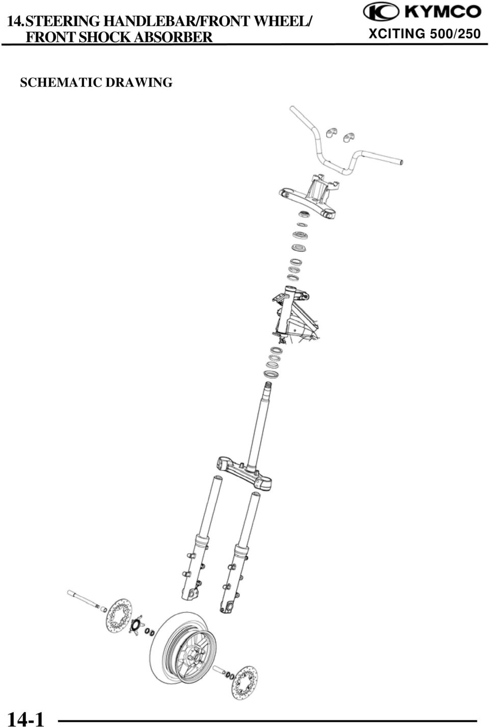
1 14 14 STEERING HANDLEBAR/FRONT WHEEL/ SCHEMATIC DRAWING SERVICE INFORMATION TROUBLESHOOTING FRONT WHEEL FORK STEERING HANDLEBAR STEERING STEM

2 SCHEMATIC DRAWING 14-1
3 SERVICE INFORMATION GENERAL INSTRUCTIONS A contaminated brake disc or pad reduces stopping power. Discard contaminated parts and clean a contaminated disc with a high quality brake degreasing agent. This section covers of the front wheel, fork, handlebar, and steering. A jack or other support is required to support the vehicle. Do not twist or bend the brake hose and pipe when servicing. Use genuine KYMCO replacement bolts and nuts for all suspension pivots and mounting points Refer to section 16 for brake system information. SPECIFICATIONS Unit: mm (in) ITEM STANDARD SERVICE LIMIT Minimum tire tread depth 1.6 (0.06) Cold tire pressure Driver only 200 kpa (2.00 kgf/cm 2, 29 psi) Driver and passenger 225 kpa (2.25kgf/cm 2, 32 psi) Axle runout 0.2 (0.008) Wheel rim runout Radial 2.0 (0.08) Axial 2.0 (0.08) TORQUE VALUES Handlebar bolt Steering stem nut Steering stem lock nut Steering top thread Steering stem pinch bolt Front axle bolt Front brake disc bolt Front fork bolt 23 N m (2.3 kgf m, 17 lbf ft) 62 N m (6.2 kgf m, 45 lbf ft) 45 N m (4.5 kgf m, 32 lbf ft) 17 N m (1.7 kgf m, 12 lbf ft) 23 N m (2.3 kgf m, 17 lbf ft) 20 N m (2 kgf m, 15 lbf ft) 42 N m (4.3 kgf m, 31 lbf ft) Lock bolt: replace with a new one. 23 N m (2.3 kgf m, 17 lbf ft) SPECIAL TOOLS Long socket wrench Bearing remover Oil seal & bearing install driver E015 E037 E
 ITEM STANDARD SERVICE LIMIT Minimum tire tread depth 1.6 (0.06) Cold tire pressure Driver only 200 kpa (2.00 kgf/cm 2, 29 psi) Driver and passenger 225 kpa (2.")
4 TROUBLESHOOTING Hard steering Steering stem top thread too tight Worn or damaged steering bearings Worn or damaged steering bearing races Bent steering stem Insufficient tire pressure Faulty front tire Steers to one side or does not track straight Damaged or loose steering bearings Bent fork Bent front axle: wheel installed incorrectly Bent frame Faulty front tire Worn or damaged front wheel bearings Worn or damaged engine mounting bushings Front wheel wobbling Bent rim Worn or damaged front wheel bearings Faulty front tire Loose front axle fasteners Wheel turns hard Faulty front wheel bearings Bent front axle Brake drug Soft suspension Weak fork spring Insufficient fluid in fork Deteriorated fork fluid Incorrect fork fluid weight Low tire pressure Hard suspension Bent fork tube Too much fluid in fork Incorrect fork fluid weight Clogged fork fluid passage High tire pressure Front suspension noise Worn slider or fork tube bushing Insufficient fluid in fork Loose fork fastener 14-3

5 FRONT WHEEL REMOVAL Loosen the front axle holder bolt. Holder bolt Front Axle Loosen the front axle bolt. Support the scooter securely using a hoist or equivalent and raise the front wheel off the ground. Remove the right and left mount bolts and front brake calipers. Bolts Pull off the front axle out and remove the front wheel. NOTE: Do not operate the front and rear brake lever after removing the front wheel. Calipers 14-4

6 Remove the right and left side collar from the wheel hub. Side Collar INSTECTION Axle Place the axle in V-blocks and measure the runout. Actual runout is 1/2 the total indicator reading. Service limit: 0.20 mm (0.008 in) Wheel Check the rim runout by placing the wheel in a truing stand. Spin the wheel slowly and read the runout using a dial indicator. Actual runout is 1/2 the total indicator reading. Service limit: Radial: 0.20 mm (0.008 in) Axial: 0.20 mm (0.008 in) 14-5
 Wheel Check the rim runout by placing the wheel in a truing stand.")
7 Wheel Bearing Turn the inner race of each bearing with your finger. The bearings should turn smoothly and quietly. Also check that the bearing outer race fits tightly in the hub. DIASSEMBLY Remove the right and left disc bolts and brake discs. Discs Remove the bolts and speed sensor guide. Speed Sensor Guide Wheel Bearing 14-6

8 Remove the dust seals Dust Seals Install the bearing remover into the bearing. Drive the bearing out of the wheel hub. Remove the distance collar and drive out the other bearing. Special tool: Bearing remover E037 NOTE: Replace the wheel bearings in pairs. Do not reuse old bearings. ASSEMBLY Pack a new bearing cavities with grease. Drive the new left bearing squarely with the sealed side facing up until it is fully seated. Special tool: Oil seal & bearing install driver E

9 Install the distance collar. Distance Collar Pack a new bearing cavities with grease. Drive the new right bearing squarely with the sealed side facing up until it is fully seated. Special tool: Oil seal & bearing install driver E014 Apply grease to the new dust seal lips. Install the dust seals into the wheel hub until there are flush with the wheel hubs. Dust Seals 14-8

10 Install the speed sensor guide. Install the plate blots and tighten them to the specified torque. Speed sensor guide Torque: 10 N m (1.0 kgf m, 7 lbf ft) Install the brake discs into wheel hub. Install new disc bolts and tighten them to the specified torque. Torque: 42 N m (4.3 kgf m, 31 lbf ft) Discs INSTALLATION Side Collar Install the side collars into the wheel hub. 14-9

11 Install the front wheel between the fork leg. Install the front axle front left side. Tighten the axle bolt to the specified torque. Front Axle Torque: 20 N m (2 kgf m, 15 lbf ft) Tighten the front axle holder bolt to the specified torque. Holder Bolt Torque: 23 N m (2.3 kgf m, 17 lbf ft) Install the right and left front calipers onto the fork leg. Install and tighten the new front caliper mount blots to the specified torque. Bolts Torque: 32 N m (3.2 kgf m, 23 lbf ft) Calipers 14-10
 Install the right and left front calipers onto the fork leg.")
12 With the front brake applied, pump the fork up and down several times to seat the axle and check brake operation. Check the brake operation by applying the brake lever. Speed Sensor Measure the speed sensor to speed sensor guide clearance. Standard (A): mm ( in) Adjust it if necessary (page 20-5). Speed Sensor Guide 14-11
: 0.3 1.2 mm (0.0012 0.048 in) Adjust it if necessary (page 20-5).")
13 FORK Upper Pinch Bolt REMOVAL Remove the front wheel (page 14-4). Remove the front fender (page 2-4). Remove the bolt and hose clamp. Remove the bolt and speed sensor (only right fork). Remove the upper fork pinch bolt. Remove the lower fork pinch bolts. Remove the fork from the handlebar post and steering stem. Bolt/Clamp Washers Speed Sensor Bolt Lower Pinch Bolts INSTALLATION Install the fork tube into steering stem and handlebar post and align the mark on the fork tube with the handlebar post surface as shown. Mark Install and tighten the upper pinch bolt to the specified. Torque: 23 N m (2.3 kgf m, 17 lbf ft) Upper Pinch Bolt 14-12

14 Tighten the lower pinch bolts to specified torque. Torque: 23 N m (2.3 kgf m, 17 lbf ft) Install the brake caliper onto the fork leg with new mount bolts. Torque: 32 N m (3.2 kgf m, 23 lbf ft) Install the brake hose clamp onto the fork leg with the bolt. Install the speed sensor onto the right fork leg and tighten the bolt. Install the front fender. Install the front wheel. Lower Pinch Bolts Bolt/Clamp Speed Sensor Bolt 14-13

15 STEERING HANDLEBAR REMOVAL Remove the front cover (page 2-11). Remove the upper handlebar cover (page 2-5). Remove the band bolt and disconnect the left handlebar switch connector. Left Handlebar Switch Connector Bolt Remove the two screws and lower handlebar cover. Screws Remove the bolts, master cylinder holders and rear master cylinders. Disconnect the left brake light switch connectors. Bolts NOTE: Keep the master cylinder upright to prevent air from entering the hydraulic system. Brake Light Switch Connectors 14-14

16 Remove the bolts, master cylinder holders and front master cylinders. Bolts NOTE: Keep the master cylinder upright to prevent air from entering the hydraulic system. Remove the screws and right handlebar switch housing. Screws Remove the bolt/right handlebar weight. Bolt/Right Handlebar Weight 14-15

17 Remove the bolts and upper holders. Holder Bolts Remove the handlebar from the handlebar post and right handlebar switch housing. Switch Housing INSTALLATION Pass the handlebar through the right handlebar switch housing

18 Align the holes on the handlebar with the pins on the handle post. Holes Pins Install the handlebar to the handle post. Holder Bolts Install the upper holders with its punch marks facing toward. Install the upper holder bolts. Tighten the front bolts first, then tighten the rear bolts. Torque: 23 N m (2.3 kgf m, 17 lbf ft) Install the throttle grip and bolt/right handlebar weight and tighten the bolt. Throttle Grip Bolt/Right Handlebar Weight 14-17

19 Align the pin on the right handlebar switch housing with the hole on the steering handle. Hole Pin Install the screws and tighten the forward screw first, then tighten the rear screw. Screws Align the pin on the rear master cylinder holder with the hole on the handlebar. Install the front master cylinders and holder with the UP mark facing up. Install the bolts and tighten the upper bolt first then tighten the lower bolt to the specified torque. Torque: 12 N m (1.2 kgf m, 9 lbf ft) Pin UP Mark Hole 14-18

20 Align the pin on the rear master cylinder holder with the hole on the handlebar. Hole Pin Install the rear master cylinders and holder with the UP mark facing up. Install the bolts and tighten the upper bolt first then tighten the lower bolt to the specified torque. UP Mark Torque: 12 N m (1.2 kgf m, 9 lbf ft) Connect the brake light switch connectors. Brake Light Switch Connectors Connect the left handlebar switch connector and tighten the band bolt Left Handlebar Switch Connector Bolt
 Connect the brake light switch connectors.")
21 STEERING STEM Clamp Bolts REMOVAL Remove the front fork (page 14-12). Remove the steering handle (page 14-14). Remove the bolts and brake hoses clamp. Remove the nut, washer and handle post. Special tool: Long socket wrench E015 Remove the brake hoses from the clamps on the steering stem. Brake Hoses 14-20
22 Remove the steering stem lock nut. Special tool: Long socket wrench F007 Remove the lock washer. Lock Washer Loosen the steering top thread. Hold the steering stem and remove the steering stem top thread. Top Thread 14-21
23 Remove the steering stem and lower bearing. Lower Bearing Steering Stem Remove the dust seal, upper inner race and upper bearing Dust Seal Upper Inner Race Upper Bearing BEARING REPLACEMENT Remove the upper bearing outer race. NOTE: Always replace the bearings and races as a set
24 Remove the lower bearing outer race. Lower Outer Race Drive a new upper bearing race into the steering head pipe. Upper Outer Race Drive a new lower bearing race into the steering head pipe. Lower Outer Race 14-23
25 Install the steering stem lock nut onto the steering to prevent the threads from being damaged when removing the lower bearing inner race from the steering stem. Lower Inner Race Remove the lower bearing inner race with a chisel or equivalent tool, being careful not to damage the steering stem. Remove the dust seal. Dust Seal Install the dust seal. Apply grease to a new lower bearing inner race using a hydraulic press. INSTALLATION Apply grease to each new bearings and inner races. Install the upper bearing, upper inner race and dust seal. Dust Seal Upper Inner Race Upper Bearing 14-24
26 Install the lower bearing onto the stem. Insert the steering stem into the steering head pipe. Lower Bearing Steering Stem Install the steering top thread. Top Thread Steering top thread tightening step: Tighten the steering top thread to specified torque. Torque: 52 N m (5.2 kgf m, 37 lbf ft) Temporarily loosen the steering stem top thread, then retighten it to specified torque. Torque: 20 N m (2 kgf m, 15 lbf ft) Turn the steering stem lock-to-lock several times to seat the bearings. Temporarily loosen the steering stem top thread. Install the fork (page 14-12). Install the front wheel (page 14-9). Install the steering top thread to the specified torque with the front wheel is grounded. Torque: 20 N m (2 kgf m, 15 lbf ft) 14-25
27 Install the lock washer aligning its tab into the groove on the steering stem. Install the steering stem lock nut. Hold the steering stem top thread and tighten the steering stem lock nut to the specified torque. Special tool: Long socket wrench F007 Torque: 55 N m (5.5 kgf m, 40 lbf ft) Make sure that the steering stem moves smoothly without play or binding. Lock Washer Lock Nut Install the handle post to the steering stem and front forks. Install the washer and nut. Tighten the handle post nut to the specified torque. Special tool: Long socket wrench E015 Torque: 62 N m (6.2 kgf m, 45 lbf ft) Washer Nut Install the brake hose clamp and tighten the bolts securely. Route the brake hoses and wires properly (page 1-15). Clamp Bolts 14-26
12. REAR WHEEL/BRAKE/SUSPENSION
 12 12 12-0 SERVICE INFORMATION... 12-1 REAR BRAKE... 12-5 TROUBLESHOOTING... 12-2 REAR SHOCK ABSORBER... 12-8 REAR WHEEL... 12-3 REAR FORK... 12-9 SERVICE INFORMATION GENERAL INSTRUCTIONS When installing
13. REAR WHEEL/BRAKE/SUSPENSION
 13. REAR WHEEL/BRAKE/SUSPENSION 13 3.5~4.5kg-m 8.0~10.0kg-m 0.8~1.2kg-m 3.0~4.0kg-m 2.4~3.0kg-m 3.5~4.5kg-m 6.0~8.0kg-m 13-0 13. REAR WHEEL/BRAKE/SUSPENSION 13 REAR WHEEL/BRAKE/SUSPENSION SERVICE INFORMATION...
Unit: mm(in) Item Standard value Service limit Axle shaft run out - 0.2(0.008)
 Item Standard value Service limit Axle shaft run out - 0.2(0.008)") Rear Wheel/Brake/Suspension 13. Rear Wheel/Brake/Suspension Service Information 13-1 Troubleshooting 13-2 Rear Wheel 13-3 Rear Cushion 13-4 Rear Swing Arm 13-7 Service Information General Safety If the
Rear Wheel/Brake/Suspension 13. Rear Wheel/Brake/Suspension Service Information 13-1 Troubleshooting 13-2 Rear Wheel 13-3 Rear Cushion 13-4 Rear Swing Arm 13-7 Service Information General Safety If the
2008 ACCORD - Front Knuckle/Hub/Wheel Bearing Replacement (page 18-13)
") 2008 ACCORD - Front Knuckle/Hub/Wheel Bearing Replacement (page 18-13) Exploded View Special Tools Required Ball joint remover, 28 mm 07MAC-SL0A202 Hub dis/assembly tool 07GAF-SD40100 Bearing driver attachment,
2008 ACCORD - Front Knuckle/Hub/Wheel Bearing Replacement (page 18-13) Exploded View Special Tools Required Ball joint remover, 28 mm 07MAC-SL0A202 Hub dis/assembly tool 07GAF-SD40100 Bearing driver attachment,
Volkswagen Jetta, Golf, GTI 1999, 2000 Brake System 46 Brakes - Mechanical Components (Page GR-46)
") 46 Brakes - Mechanical Components (Page GR-46) Front brakes Brake pads, removing and installing Brake pads, removing and installing FN 3 brake caliper, servicing FS III brake caliper, servicing Rear wheel
46 Brakes - Mechanical Components (Page GR-46) Front brakes Brake pads, removing and installing Brake pads, removing and installing FN 3 brake caliper, servicing FS III brake caliper, servicing Rear wheel
Volkswagen Jetta, Golf, GTI 1999, 2000 Brake System 47 Brakes - Hydraulic Components (Page GR-47)
") 47 Brakes - Hydraulic Components (Page GR-47) FS III front brake calipers, servicing Front brake caliper piston, removing and installing FN 3 front brake calipers, servicing Front caliper piston, removing
47 Brakes - Hydraulic Components (Page GR-47) FS III front brake calipers, servicing Front brake caliper piston, removing and installing FN 3 front brake calipers, servicing Front caliper piston, removing
DO NOT attempt to repair hub and wheel bearing assembly.
 Page 1 of 6 HUB & WHEEL BEARINGS (WITH PULSE VACUUM HUBLOCK) DO NOT attempt to repair hub and wheel bearing assembly. Removal DO NOT remove hub lock assembly by prying on hub lock legs. This can crack
Rear wheel brakes, servicing. Стр. 1 из 45. Note:
 Volkswagen Touareg - Rear wheel brakes, servicing Стр. 1 из 45 46-2 Rear wheel brakes, servicing Rear brakes, FN 44 brake caliper, servicing Note: After replacing brake pads, depress brake pedal firmly
STEERING SYSTEM - POWER
 STEERING SYSTEM - POWER 1990 Nissan 240SX 1990 STEERING Nissan - Power Rack & Pinion Axxess, Maxima, Pulsar NX, Sentra, Stanza, 240SX, 300ZX DESCRIPTION The power steering system consists of a rack and
Front axle components, overview
 just a test. Front axle components, overview 40-1 General Information Load bearing components and parts of the suspension must not be welded or straightened. Vehicles without drive axle must not be moved,
Front brakes (FN- 3), servicing
, servicing") j a t Front brakes (FN- 3), servicing 46-1 Front brakes, servicing Note: Install complete repair kit. After replacing brake pads and before moving vehicle, depress brake pedal several times firmly to properly
j a t Front brakes (FN- 3), servicing 46-1 Front brakes, servicing Note: Install complete repair kit. After replacing brake pads and before moving vehicle, depress brake pedal several times firmly to properly
1993 SUSPENSION Volkswagen Front. EuroVan
 Article Text ARTICLE BEGINNING 1993 SUSPENSION Volkswagen Front EuroVan DESCRIPTION FWD independent suspension is an double-wishbone type with torsion bars mounted on upper control arm. Wheel is supported
REAR AXLE 27-1 CONTENTS 27109000161 ON-VEHICLE SERVICE... 3 GENERAL INFORMATION... 2 SERVICE SPECIFICATIONS... 2 SPECIAL TOOLS... 2 REAR AXLE HUB...
 27-1 REAR AXLE CONTENTS 27109000161 GENERAL INFORMATION... 2 SERVICE SPECIFICATIONS... 2 SPECIAL TOOLS... 2 ON-VEHICLE SERVICE... 3 Wheel Bearing Axial Play Check... 3 Wheel Bearing Rotary-Sliding Resistance
SUSPENSION DIAGNOSIS
 SECTION 2A SUSPENSION DIAGNOSIS TABLE OF CONTENTS Diagnosis... 2A-2 General Diagnosis... 2A-2 Hub and Bearing... 2A-7 2A-2 SUSPENSION DIAGNOSIS DIAGNOSIS GENERAL DIAGNOSIS Problems in the steering, the
Drive shaft, servicing
 Volkswagen Passat B6 - Drive shaft, servicing Стр. 1 из 41 40-7 Drive shaft, servicing Drive shafts, overview I - Assembly overview: Drive axle with CV joint VL100 40-7, Drive axle with CV joint VL100,
DRIVE AND DRIVEN PULLEY
 11 DRIVE AND DRIVEN PULLEY SCHEMATIC DRAWING ------------------------------------------------- 11-1 SERVICE INFORMATION------------------------------------------------ 11-2 TROUBLESHOOTING-----------------------------------------------------
2007 Hummer H3. 2007 BRAKES Disc Brakes - H3. Fastener Tightening Specifications Specification Application
 2007 BRAKES Disc Brakes - H3 SPECIFICATIONS FASTENER TIGHTENING SPECIFICATIONS Fastener Tightening Specifications Specification Application Metric English Backing Plate Bolts 135 N.m 100 lb ft Brake Hose
Installation instruction do88 Intercooler for Volvo S40 / V50 / C30
 Installation instruction do88 Intercooler for Volvo S40 / V50 / C30 This instruction shows how to replace the OEM intercooler with our performance intercooler. 2. 3. 1. 4. 5. Part number: ICM-170 6. At
Verify caster, camber and toe-in are correct before proceeding.
 If rotating the tie rod end 360 degrees changes the toe-in too much, use the rack tie rod to make smaller adjustments. Put the tie rod end in the steering arm and snug the castle nut before adjusting.
INSTALLATION INSTRUCTIONS. 6108 Air Spring Kit 2011+ Ford F250 Single Wheel 4WD 2011+ Ford F350 Dually 4WD (2011 F350 Single Wheel 4WD use p/n 6113)
") INSTALLATION INSTRUCTIONS 6108 Air Spring Kit 2011+ Ford F250 Single Wheel 4WD 2011+ Ford F350 Dually 4WD (2011 F350 Single Wheel 4WD use p/n 6113) Thank you for purchasing a quality Hellwig Product. PLEASE
INSTALLATION INSTRUCTIONS 6108 Air Spring Kit 2011+ Ford F250 Single Wheel 4WD 2011+ Ford F350 Dually 4WD (2011 F350 Single Wheel 4WD use p/n 6113) Thank you for purchasing a quality Hellwig Product. PLEASE
INSTRUCTIONS. FLHR/C/S (Road King) FRONT END LOWERING KIT 1WARNING -J03242 REV. 10-19-04. General. Removal (Left and Right Forks) Kit Number 54614-05
 FRONT END LOWERING KIT 1WARNING -J03242 REV. 10-19-04. General. Removal (Left and Right Forks) Kit Number 54614-05") INSTRUCTIONS -J04 REV. 0-9-04 General FLHR/C/S (Road King) FRONT END LOWERING KIT This kit is designed for installation on 00 and later FLHR/C/S Model Motorcycles. Road King models use the conventional
INSTRUCTIONS -J04 REV. 0-9-04 General FLHR/C/S (Road King) FRONT END LOWERING KIT This kit is designed for installation on 00 and later FLHR/C/S Model Motorcycles. Road King models use the conventional
ARVINMERITOR UNITIZED FRONT WHEEL HUB INSPECTION AND MAINTENANCE
 SERVICE BULLETIN (Also applies to Mack Trucks Australia) NUMBER: SB-423-002 DATE: 8/23/02 MODEL: All with FF981 Front Axle ARVINMERITOR UNITIZED FRONT WHEEL HUB INSPECTION AND MAINTENANCE The ArvinMeritor
6 inch A-Arm Lift Kit WARNING: 16-018/16-019. installation instructions. will fit CLUB CAR DS. included:
 Revised May 205 6-08/6-09 6 inch A-Arm Lift Kit will fit CLUB CAR DS installation instructions included: Rear Lift Blocks Main Suspension Assembly Spindles A-Arms Rear Shock Mounting Plates U-Bolts WARNING:
2011-14 F250 6 RADIUS ARM KIT
 92154000 Thank you for choosing Rough Country for your suspension needs. 2011-14 F250 6 RADIUS ARM KIT Rough Country recommends a certified technician installs this system. In addition to these instructions,
INSIDE ENGINE COMPARTMENT TOYOTA AIR CONDITIONING ENGLISH EUROPE,GENERAL,AUSTRALIA
 INSIDE ENGINE COMPARTMENT TOYOTA AIR CONDITIONING ENGLISH EUROPE,GENERAL,AUSTRALIA INTRODUCTION IMPORTANT NOTICE This manual has been designed for technicians who are qualified and educated in the proper
DiscPlus DX195 and DX225 Air Disc Brakes
 Revised 11-04 Technical Bulletin Revised 1 Technical 11-04 Bulletin DiscPlus DX195 and DX225 Air Disc Brakes Inspection, Installation and Diagnostics Air Disc Brake Inspection Intervals and Procedures
1/29/2008 DR125 / DR150. Baja Motorsports Inc. P.O. Box 61150 Phoenix, AZ 85082 Toll Free: 888-863-2252 PARTS AND PRICES ARE SUBJECT TO CHANGE 1 of 55
 DR125 / DR150 Toll Free: 888-863-2252 PARTS AND PRICES ARE SUBJECT TO CHANGE 1 of 55 CYLINDER HEAD ASSY. 1 125-001 883099006937 CYLINDER HEAD COVER 1 1 2 125-002 883099006944 BOLT M6X28 2 3 3 125-003 883099006951
DR90. Baja Motorsports Inc. P.O. Box 61150 Phoenix, AZ 85082 Toll Free: 888-863-2252 PART NUMBERS AND PRICES ARE SUBJECT TO CHANGE 1 of 51
 DR90 Toll Free: 888-863-2252 PART NUMBERS AND PRICES ARE SUBJECT TO CHANGE 1 of 51 CYLINDER & CYLINDER HEAD 1 DR90-001 842645048166 CYLINDER 1 1 2 DR90-002 842645048173 GASKET, CYLINDER 1 1 3 DR90-003
AXLE SHAFTS - FRONT. 1993 Toyota Celica DESCRIPTION REMOVAL, DISASSEMBLY, REASSEMBLY & INSTALLATION. 1993 DRIVE AXLES Toyota FWD Axle Shafts
 AXLE SHAFTS - FRONT 1993 Toyota Celica 1993 DRIVE AXLES Toyota FWD Axle Shafts Toyota; Celica DESCRIPTION Axle shafts transfer power from transaxle to driving wheels. All axle shafts consist of a shaft
11. COOLING SYSTEM 11-0 COOLING SYSTEM BET & WIN 50
 11 COOLING SYSTEM SERVICE INFORMATION------------------------------------------------ 11-1 TROUBLESHOOTING----------------------------------------------------- 11-1 RADIATOR ------------------------------------------------------------------
DR125 and DR150 Hensim Dirt Runner 125cc and 150cc Dirt Bike (VIN PREFIX LLCH or LUAH)
") Parts Lists - DR125 and DR150 Hensim Dirt Runner 125cc and 150cc Dirt Bike (VIN PR... Page 1 of 25 Product Information Baja Web > Product Information > Parts Lists > DIRTBIKE > DR125 and DR150 Hensim Dirt
Parts Lists - DR125 and DR150 Hensim Dirt Runner 125cc and 150cc Dirt Bike (VIN PR... Page 1 of 25 Product Information Baja Web > Product Information > Parts Lists > DIRTBIKE > DR125 and DR150 Hensim Dirt
INSTALLATION INSTRUCTIONS. 6111 Air Spring Kit 2011+ Ford F250/F-350 Single Wheel 2WD 2011+ Ford F350 Dually 2WD IMPORTANT NOTES
 INSTALLATION INSTRUCTIONS 6111 Air Spring Kit 2011+ Ford F250/F-350 Single Wheel 2WD 2011+ Ford F350 Dually 2WD Thank you for purchasing a quality Hellwig Product. PLEASE READ THIS INSTRUCTION SHEET COMPLETELY
INSTALLATION INSTRUCTIONS COMPETITION SERIES COILOVER SUSPENSION SYSTEM 03+ Scion xb
 INSTALLATION INSTRUCTIONS COMPETITION SERIES COILOVER SUSPENSION SYSTEM 03+ Scion xb NOTE: Progress Technology products should only be installed by a qualified licensed mechanic experienced in the installation
Model Year: 2010 Model: Prius Doc ID: RM000001Y3B015X. Title: ALIGNMENT / HANDLING DIAGNOSIS: FRONT WHEEL ALIGNMENT: ADJUSTMENT (2010 Prius)
") Last Modified: 5-3-2010 6.4 N From: 200904 Model Year: 2010 Model: Prius Doc ID: RM000001Y3B015X Title: ALIGNMENT / HANDLING DIAGNOSIS: FRONT WHEEL ALIGNMENT: ADJUSTMENT (2010 Prius) ADJUSTMENT If the
Last Modified: 5-3-2010 6.4 N From: 200904 Model Year: 2010 Model: Prius Doc ID: RM000001Y3B015X Title: ALIGNMENT / HANDLING DIAGNOSIS: FRONT WHEEL ALIGNMENT: ADJUSTMENT (2010 Prius) ADJUSTMENT If the
2003 ACCORD - Automatic Transmission Removal
 2003 ACCORD - Automatic Transmission Removal Special Tools Required Engine support hanger, A and Reds AAR-T-12566 Engine hanger balancer bar VSB02C000019 Front subframe adapter VSB02C000016 These special
White Industries Rear Hub Instructions
 White Industries Rear Hub Instructions Tool required: 2mm allen/hex wrench, 19mm socket, 20mm socket, and mallet. 1. Loosen the set screws located in the adjusting collar by using a 2mm allen wrench inserted
1/29/2008 DR70. Baja Motorsports Inc. P.O. Box 61150 Phoenix, AZ 85082 Toll Free: 888-863-2252 PART NUMBERS PRICES ARE SUBJECT TO CHANGE 1 of 43
 DR70 Toll Free: 888-863-2252 PART NUMBERS PRICES ARE SUBJECT TO CHANGE 1 of 43 CYLINDER & CYLINDER HEAD 1 DR70-001 883099044472 CYLINDER 1 1 2 DR70-002 883099044489 GASKET, CYLINDER 1 1 3 DR70-003 883099044496
ENGINE FUEL FUEL FILTER... FUEL HEATER... INJECTOR... SUPPLY PUMP... COMMON RAIL... FUEL PRESSURE LIMITTER...
 FUEL FILTER............................ FUEL HEATER.......................... INJECTOR.............................. SUPPLY PUMP.......................... COMMON RAIL.......................... FUEL PRESSURE
SCION tc 2005-2008 COIL OVER SUSPENSION Preparation
 SCION tc 2005-2008 COIL OVER SUSPENSION Preparation Part Number: PTR11-21070 NOTE: Part number of this accessory may not be the same as the part number shown. Kit Contents: Item # Quantity Reqd. Description
16 April 2012 1032011-F 1994-2002 Dodge Adjustable Track bar with Relocation Bracket 1
 16 April 2012 1032011-F 1994-2002 Dodge Adjustable Track bar with Relocation Bracket 1 BD Adjustable Track Bar w/bracket Dodge 2500-3500 4WD Models 1994-2002 Dodge 1500 4WD Model 1994-2001 P/N# 1032011-F
DR50 Hensim Dirt Runner 49cc Dirt Bike (VIN PREFIX LLCH or LUAH)
") Page 1 of 21 Product Information Baja Web > Product Information > Parts Lists > DIRTBIKE > DR50 Hensim Dirt Runner 49cc Dirt Bike (VIN PREFIX LLCH or LUAH) DR50 Hensim Dirt Runner 49cc Dirt Bike (VIN PREFIX
Page 1 of 21 Product Information Baja Web > Product Information > Parts Lists > DIRTBIKE > DR50 Hensim Dirt Runner 49cc Dirt Bike (VIN PREFIX LLCH or LUAH) DR50 Hensim Dirt Runner 49cc Dirt Bike (VIN PREFIX
CHROME FRONT BRAKE MASTER CYLINDER KIT
 -J075 REV. 009-0-0 CHROME FRONT BRAKE MASTER CYLINDER KIT GENERAL Kit Number 5-99D, 5-99D Models These Chrome Master Cylinder Kits are designed to replace the original equipment front brake master cylinder
Service Manual Rol-Lift
 R 2000 Service Manual Rol-Lift Series: T and E Developed by Generic Parts Service This manual is intended for basic service and maintenance of the Rol-Lift pallet jack. The pallet jacks you are servicing
INTRODUCTION KINGPIN REPLACEMENT
 KINGPIN REPLACEMENT Author: Randy Baumann All information, illustrations and specifications are based on the best information available at the time of publication. The author cannot guarantee the accuracy
Webinar Series. Committee. Disc Brake Wheels Off Inspection and Reline. Presents
 1 APTA Bus Webinar Technical Series Maintenance Committee Webinar Series Presents Disc Brake Wheels Off Inspection and Reline January 21, 2015 2 Introduction Welcome to today s webinar in which we will
DANA 30 MANUAL HUB CONVERSION KIT
 DANA 30 MANUAL HUB CONVERSION KIT 12194 PLEASE READ AND UNDERSTAND ALL INSTRUCTIONS BEFORE YOU BEGIN Your safety and the safety of other motorists is very important. Your Jeep is an off road capable vehicle
FOR ANY QUESTIONS, PLEASE CALL US @ 727.347.9915 M-F 8:00a.m.-8:00p.m. EST. REAR BRAKES 1 AEROSPACE COMPONENTS 727.347.9915
 REAR BRAKES 1 AEROSPACE COMPONENTS 727.347.9915 REAR BRAKES Before getting started, remove all stock braking components. Pre-assembly of parts: Clean the bolts and the threads in the hat with acetone.
MODEL 565E - 22 TON AIR/HYDRAULIC AXLE JACK
 1 565AKHU HYDRAULIC 1.22 O-RING - 2 REQUIRED UNIT 1.23 O-RING COMPLETE 1.24 TEFLON O-RING 2 REQUIRED 1.3 EXTENSION SCREW 1.3A SPRING PIN 1.4 SPRING SUPPORT 1.5 SCREW BUSHING 1.6 Y SHAPE SEAL RING 1.7 HEAD
Owner s Manual Read and keep this manual. Patents World Wide
 Owner s Manual Read and keep this manual. Patents World Wide S & S Industries, Inc., Sarasota, FL, USA www.trail-gator.com Copyright 2008 All Rights Reserved The following manual is provided to assist
DR90. Baja Motorsports Inc. P.O. Box 61150 Phoenix, AZ 85082 Toll Free: 888-863-2252 PART NUMBERS AND PRICES ARE SUBJECT TO CHANGE 1 of 51
 DR90 Toll Free: 888-863-2252 PART NUMBERS AND PRICES ARE SUBJECT TO CHANGE 1 of 51 CYLINDER & CYLINDER HEAD Part UPC Number Description Baja Description 1 DR90-001 842645048166 CYLINDER 1 1 2 DR90-002
1.00 IN (25.4 MM) DIAMETER BATWING MINI-APE HANDLEBAR KITS
 DIAMETER BATWING MINI-APE HANDLEBAR KITS") REV. 04-09-09.00 IN (5.4 MM) DIAMETER BATWING MINI-APE HANDLEBAR KITS GENERAL Kit Numbers 57474-, 57485- Models For model fitment information, see the P&A retail catalog or the Parts and Accessories section
REV. 04-09-09.00 IN (5.4 MM) DIAMETER BATWING MINI-APE HANDLEBAR KITS GENERAL Kit Numbers 57474-, 57485- Models For model fitment information, see the P&A retail catalog or the Parts and Accessories section
Rebuild Instructions for 70001 and 70010 Transmission
 Rebuild Instructions for 70001 and 70010 Transmission Brinn, Incorporated 1615 Tech Drive Bay City, MI 48706 Telephone 989.686.8920 Fax 989.686.6520 www.brinninc.com Notice Read all instructions before
Range Road RR Series Semi-Automatic Firewood Processor. Crated Unit Assembly Manual
 Range Road RR Series Semi-Automatic Firewood Processor Crated Unit Assembly Manual 1 1) Undo 8-18mm x 19mm Nuts and bolts, 2 on each leg of top frame 2) Lift top of Metal crate off and move out of work
1/29/2008 DR50. Baja Motorsports Inc. P.O. Box 61150 Phoenix, AZ 85082 Toll Free: 888-863-2252 PART NUMBERS PRICES ARE SUBJECT TO CHANGE 1 of 45
 DR50 Toll Free: 888-863-2252 PART NUMBERS PRICES ARE SUBJECT TO CHANGE 1 of 45 CYLINDER & CYLINDER HEAD Part UPC Number Description Baja Description 1 DR50-001 842645074424 CYLINDER 1 1 2 DR50-002 842645074431
3. INSPECTION/ADJUSTMENT
 3 3 INSPECTION/ADJUSTMENT SERVICE INFORMATION-------------------------------------------------- 3-1 MAINTENANCE SCHEDULE (XCITING 500) ------------------------- 3-3 MAINTENANCE SCHEDULE (XCITING 250) -------------------------
Trillium 40 Axis Spring Tensioner Wire Replacement Instructions
 Trillium 40 Axis Spring Tensioner Wire Replacement Instructions 1 Overview The objective is to replace the broken axis spring tensioner wire. This requires the following tasks: 1. Remove the seismometer
Class 5 to 7 Truck and Bus Hydraulic Brake System
 Class 5 to 7 Truck and Bus Hydraulic Brake System Diagnostic Guide 1st Edition * 5+0 Important Service tes The information in this publication was current at the time of printing. The information presented
Parts#MB003-003 Reverse Gear MAMBA (Monoblock for Cable operated) For 5 speed Trans., '87 to '06 Big Twin models (except '06 Dyna)
 For 5 speed Trans., '87 to '06 Big Twin models (except '06 Dyna)") Installation Instructions Reverse Gear MAMBA (Monoblock for Cable operated) Read and become familiar with these installation instructions before start. Two Piece for H-D 5 Speed Trans., Cable operated
Installation Instructions Reverse Gear MAMBA (Monoblock for Cable operated) Read and become familiar with these installation instructions before start. Two Piece for H-D 5 Speed Trans., Cable operated
ReadyLift (Part# 66-5075) Strut Extension, Installation Instructions Toyota Tundra New Body Style 2WD & 4WD
 Strut Extension, Installation Instructions Toyota Tundra New Body Style 2WD & 4WD") SAFETY WARNING: recommends this system be installed by a professional technician. In addition to these instructions, professional knowledge of disassembly/ reassembly procedures and post installation checks
SAFETY WARNING: recommends this system be installed by a professional technician. In addition to these instructions, professional knowledge of disassembly/ reassembly procedures and post installation checks
HC-3000 SERIES RAKE Parts Breakdown DURABILT INDUSTRIES, LLC - 1810 AIRPORT ROAD POCAHONTAS ARKANSAS 72455
 HC-3000 SERIES RAKE Parts Breakdown 1 SPRING TOWER PARTS PAGE 4 RAKE WHEEL AND ARM PARTS PAGE 8 PIVOT PARTS PAGE 6 6 2,3,4 23 21 7 22 24 HUB & SPINDLE PARTS 8 THRU 20 HYDRAULIC PARTS PAGES 10 AND 12 1
WHEEL ALIGNMENT 4WD SA 6
 SA6 WHEEL ALIGNMENT 4WD 1. MAKE FOLLOWING CHECKS AND CORRECT ANY PROBLEMS (a) Check the tires for wear and proper inflation. Cold tire inflation pressure: See page A25 (b) Check the wheel runout. Lateral
READ AND UNDERSTAND ALL INSTRUCTIONS AND WARNINGS PRIOR TO INSTALLATION OF SYSTEM AND OPERATION OF VEHICLE.
 491 W. Garfield Ave., Coldwater, MI 49036 Phone: 517-279-2135 Web/live chat: www.bds-suspension.com E-mail: tech-bds@sporttruckusainc.com Product: GM Leaf Spring READ AND UNDERSTAND ALL INSTRUCTIONS AND
Drum Brake Owners Manual
 Drum Brake Owners Manual TIE DOWN ENGINEERING, Inc. 5901 Wheaton Drive, Atlanta, GA 30336 www.tiedown.com (404) 344-0000 Fax (404) 349-0401 2007 TIE DOWN ENGINEERING, INC. ALL RIGHTS RESERVED Instruction
TRANS-05, Torque Tube Removal, Rebuilding, and Installation
 TRANS-05, Torque Tube Removal, Rebuilding, and Installation Tools Metric Wrench Set Metric Socket Set Jack Stands (6 minimum) Floor Jack 8mm Cheesehead socket (also referred to as 12 point internal socket
Section 6 Brake Drum Failure Analysis. Brake Drum Wear Conditions. What is Normal Wear? What is Deep or Excessive Wear? WARNING. Deep, Uniform Wear
 Section Brake Drum 6 Failure Analysis WARNING To prevent serious eye injury, always wear safe eye protection when you perform vehicle maintenance or service. Figure 6.1 ASBESTOS AND NON-ASBESTOS FIBERS
2005-2007 Ford Focus Front Brake Rotors
 2005-2007 Ford Focus Front Brake Rotors Replacement Replacing the rotors in 2005-2007 Ford Focus models with rear drum brakes. Written By: David Hodson INTRODUCTION The steps in this guide are used to
»Product» Safety Warning
 C1200 Installation Instructions 2007-2016 Chevy/GM 1500 2/4wd 2" Strut Spacer Lift Read and understand all instructions and warnings prior to installation of product and operation of vehicle. Zone Offroad
LG G5 Chassis Brace Gen 5 Camaro THE MOST POWERFUL HEADERS ON THE PLANET Brought to you by LG Motorsports 972-429-1963
 LG G5 Chassis Brace Gen 5 Camaro THE MOST POWERFUL HEADERS ON THE PLANET Brought to you by LG Motorsports 972-429-1963 Thank you for purchasing LG Motorsports products for your Gen 5 Camaro. Parts Inventory:
Cooling system components, removing and installing
 Engine BHW Cooling system components, removing and installing Page 1 / 24 19-1 Cooling system components, removing and installing Warning! When doing any repair work, especially in the engine compartment,
Subject: Pre-Formed and Pre-Flared Hydraulic Brake Pipe Kits Now Available for Service
 Subject: Pre-Formed and Pre-Flared Hydraulic Brake Pipe its Now Available for Service Models: 2000-2006 adillac Escalade Models 2000-2006 hevrolet Avalanche, Suburban, Tahoe 1999-2007 hevrolet Silverado
M-2004-MBA Brake Duct Kit 2013 BOSS 302, Mustang GT and California Special INSTALLATION INSTRUCTIONS
 Please visit www.fordracingparts.com for the most current instruction information.!!! PLEASE READ ALL OF THE FOLLOWING INSTRUCTIONS CAREFULLY PRIOR TO INSTALLATION. AT ANY TIME YOU DO NOT UNDERSTAND THE
WARRANTY INFORMATION
 (800) 603-1437 WARRANTY INFORMATION Products manufactured by Manufacturer bear the following limited warranty: Manufacturer warrants that goods delivered will be of the kind and quality described in the
2100 AD 015 0009 Mirror Elevator Ball Nut Replacement Procedure
 2100 AD 015 0009 Mirror Elevator Ball Nut Replacement Procedure Derek Guenther 1/28/2015 Rev. Purpose The purpose of this document is to describe the procedure necessary to replace one of the ball nuts
Trouble Shooting Tech Tips Operation
 Steering Components TroubleShooting Tech Tips Table of Contents Basic Steering System Operation 2 Sector Shaft Adjustments 4 Drag Link Adjustment 5 Relief Valve/Unloading Valve Adjustment 6 Ross TAS Automatic
Ford F-250 / 350 2-1/2 Coil Kit. Ford F-250, F350 2011-2015. Part#: 013255
 Part#: 013255 Ford F-250 / 350 2-1/2 Coil Kit Ford F-250, F350 2011-2015 Rev.040815 491 W. Garfield Ave., Coldwater, MI 49036. Phone: 517-279-2135 Web/live chat: www.bds-suspension.com. E-mail: tech@bds-suspension.com
assembly instructions
 assembly instructions 1 // this guide is for Urban Chic gents & ladies. // this guide is for Urban Chic gents & ladies. 2 1 x ph screwdriver 2 x 10mm spanners 1 x 15mm spanners 1 x 13mm spanners 1 x 6mm
SLACK PERFORMANCE KARTS
 SLACK PERFORMANCE KARTS SET UP GUIDE Thank you for purchasing a 2013 Slack Axiom Chassis. Performance Mfg. strives to provide you with the very best chassis and components on the market today. Your satisfaction
Slide the new steering column shaft through the steering column from the driver compartment.
 Slide the new steering column shaft through the steering column from the driver compartment. Push the column shaft through the steering column until the machined end is out past the column lower bushing.
2003 Audi A4. AUDI' '3.0L V6 - AVK Engine - A4 & A6
 Installation (A4) CAUTION: Before installation, ensure camshafts are aligned, crankshaft is locked in place and camshaft gear bolts are loose as described in removal procedures. When turning camshaft,
ZAPPY 3 OWNER S MANUAL. Read this manual completely before riding your Electric ZAPPY 3.
 ZAPPY 3 OWNER S MANUAL Read this manual completely before riding your Electric ZAPPY 3. TECHNICAL INFORMATION Model No. : ZAPPY 3 Product size Type of motor Motor power Battery type Battery Charger Charging
Tool And Material Checklist
 HOW - TO CV JOINTS CV JOINTS Tool And Material Checklist Screwdriver Metal Shears Breaker Bar or Torque Wrench Assorted Wrenches Wire Evaporating Spray Solvent Pusher Tool Vise Snap Ring or Duckbill Pliers
GTI VR6 Front Wheel Bearing DIY http://www.gtishrine.com
 GTI VR6 Front Wheel Bearing DIY http://www.gtishrine.com This procedure covers replacing the front wheel bearings. Tools and Parts required: Wheel Bearing Puller w/ ABS adapter. Available for rent from
SERVICE PARTS LIST PAGE 1 OF 6 BASE ASSEMBLY SPECIFY CATALOG NO. AND SERIAL NO. WHEN ORDERING PARTS 12" DUAL BEVEL COMPOUND MITER SAW B27A
 PAGE 1 OF 6 BASE ASSEMBLY 00 0 EXAMPLE: Component Parts (Small #) Are Included When Ordering The Assembly (Large #). SPECIFY CATALOG NO. AND NO. WHEN ORDERING PARTS 1 02-80-0050 Thrust Bearing (1) 2 05-80-0510
TECHNICAL BULLETIN. Meritor WABCO Cab Leveling Valves and Chassis Leveling Valves. How the Cab Leveling and Chassis Leveling Valves Work
 Revised 02-00 TECHNICAL BULLETIN Meritor WABCO Cab Leveling Valves and Chassis Leveling Valves This technical bulletin covers both cab and chassis leveling valves manufactured by Meritor WABCO. While the
SUSPENSION 2-1 SUSPENSION TABLE OF CONTENTS
 PL SUSPENSION 2-1 SUSPENSION TABLE OF CONTENTS page WHEEL ALIGNMENT... 1 FRONT SUSPENSION... 9 page REAR SUSPENSION... 35 WHEEL ALIGNMENT TABLE OF CONTENTS page DESCRIPTION AND OPERATION WHEEL ALIGNMENT...1
AXLE SHAFTS - FRONT. 1998 Pontiac Bonneville MODEL IDENTIFICATION DESCRIPTION & OPERATION TROUBLE SHOOTING REMOVAL & INSTALLATION
 AXLE SHAFTS - FRONT 1998 Pontiac Bonneville 1998-99 DRIVE AXLES FWD Axle Shafts - Cars - "C", "G" & "H" Bodies GM Aurora, Bonneville, Eighty Eight, LeSabre, LSS, Park Avenue, Regency, Riviera MODEL IDENTIFICATION
TITAN 13 x 2 ½ BRAKES
 INSTALLATION INSTRUCTION AND SERVICE MANUAL Actuator/Trailer Dealer - Please provide these instructions to the consumer. Consumer - Read and follow these instructions. Keep them with the trailer for future
LIFT-505. BMF Lift Kit. Yamaha Drive Gas or Electric. Installation Instructions
 LIFT-505 BMF Lift Kit Yamaha Drive Gas or Electric Installation Instructions Contents of LIFT-505 Yamaha Drive BMF Lift Kit: a (1 ea.) BMF A-Arm Assembly b (1 ea.) Driver Side Shock Tower c (1 ea.) Passenger
ASSEMBLY MANUAL SE-4S35
 Automatic drive ASSEBLY ANUAL SE-4S35 AI-4S35 SG-4R35 Battery box otor unit Inter-4 hub CONTENTS WARNING 1 INSTALLATION CONITIONS Battery box Speed sensor Cable lengths and diameters otor unit Recommended
REMOVAL AND INSTALLATION
 303-01C-1 REMOVAL AND INSTALLATION Engine Body On Special Tool(s) Adapter For 303-D043 303-D043-02 or equivalent Special Tool(s) 303-01C-1 Turbocharger Lifting Bracket 303-1266 Wrench, Fan Clutch Nut 303-214
Thank You For Choosing. INSTALLATION INSTRUCTIONS Portal Gear Hubs Polaris RZR 800. (installation performed on 60 Model) (Right) (Left)
 (Right) (Left)") 740B Clifty Drive Madison, Indiana 47250 812-574-7777 INSTALLATION INSTRUCTIONS Portal Gear Hubs Polaris RZR 800 A (installation performed on 60 Model) Item Description Qty A Rotor 4 B Gear Box, L 2 C
740B Clifty Drive Madison, Indiana 47250 812-574-7777 INSTALLATION INSTRUCTIONS Portal Gear Hubs Polaris RZR 800 A (installation performed on 60 Model) Item Description Qty A Rotor 4 B Gear Box, L 2 C
BR150 Pmi Baja Reaction 150cc Go Kart (VIN PREFIX L4VM)
") Page 1 of 21 Product Information Baja Web > Product Information > Parts Lists > GOKART > BR150 Pmi Baja Reaction 150cc Go Kart (VIN PREFIX L4VM) BR150 Pmi Baja Reaction 150cc Go Kart (VIN PREFIX L4VM)
Page 1 of 21 Product Information Baja Web > Product Information > Parts Lists > GOKART > BR150 Pmi Baja Reaction 150cc Go Kart (VIN PREFIX L4VM) BR150 Pmi Baja Reaction 150cc Go Kart (VIN PREFIX L4VM)
SELF-STEERING AXLE TABLE OF CONTENTS
 SELF-STEERING AXLE TABLE OF CONTENTS Section 1 - Introduction Section 2 - Pre-Installation Check List Section 3 - Ride Height Adjustments Section 4 - Suspension Mount Section 5 - Axle Mount Section 6 -
46431x92A Garden Tractor (1998) Page 1 of 16 Body Chassis
 Page 1 of 16 Body Chassis") 46431x92A Garden Tractor (1998) Page 1 of 16 Body Chassis 46431x92A Garden Tractor (1998) Page 2 of 16 Body Chassis 1 092546E701 Bracket, Seat 2 091963 Z Plate Assembly, Switch 3 164X26 Spring, Compression
46431x92A Garden Tractor (1998) Page 1 of 16 Body Chassis 46431x92A Garden Tractor (1998) Page 2 of 16 Body Chassis 1 092546E701 Bracket, Seat 2 091963 Z Plate Assembly, Switch 3 164X26 Spring, Compression
FRONT TURN SIGNAL RELOCATION KIT
 -J0 REV. 00-0-0 FRONT TURN SIGNAL RELOCATION KIT GENERAL Kit Number -0 Models This kit fits 00 and later Dyna model motorcycles (except FXDSE), relocating the front turn signal from the handlebars to the
OPERATOR S INSTRUCTION MANUAL
 POWER JACK MATERIAL MOVER OPERATOR S INSTRUCTION MANUAL WARNING: Serious injury may result if this product is misused. The manufacturer provides the following instructions for use and care of this equipment
MEASURING WHEEL ALIGNMENT
 MEASURING WHEEL ALIGNMENT 2003-04 WHEEL ALIGNMENT Specifications & Procedures - Hummer - H2 Steering and vibration complaints are not always the result of improper alignment. One possible cause is wheel
Number Wheeler P/N Description Set Rex P/N Notes 1 603500 Base 1 J001 2 603501 Support, Right 1 J002 3 603502 Support, Left 1 J003 4 600328 Nut (M8)
") 1 603500 Base 1 J001 2 603501 Support, Right 1 J002 3 603502 Support, Left 1 J003 4 600328 Nut (M8) 4 5 600130 Spring Washer (8mm) 4 6 600344 Roll Pin (M6x30) 4 7 600129 Socket Hd Cap Screw (M8x25) 4 8
1 603500 Base 1 J001 2 603501 Support, Right 1 J002 3 603502 Support, Left 1 J003 4 600328 Nut (M8) 4 5 600130 Spring Washer (8mm) 4 6 600344 Roll Pin (M6x30) 4 7 600129 Socket Hd Cap Screw (M8x25) 4 8
Volkswagen Phaeton 44-2 Wheel and tire mounting Wheel mounting Mounting tires Pressing off tires Dismounting tires Mounting tires
 Wheel and tire mounting Стр. 1 из 1 Volkswagen Phaeton 44-2 Wheel and tire mounting Wheel mounting Wheel bolt to hub Torque specification: 120 Nm Mounting tires The tires are installed as usual, but note
Recall R136 Front Lower Ball Joints Check Torque or Replace
 SERVICE DATE /00 Amended /00 TECHNICAL BULLETIN Recall R6 Front Lower Ball Joints Check Torque or Replace MODEL VIN Remove and destroy Bulletin S04-R6, dated /00. Replace with this Bulletin. Revisions