DRIVE AND DRIVEN PULLEY
|
|
|
- Harold Bruce
- 9 years ago
- Views:
Transcription
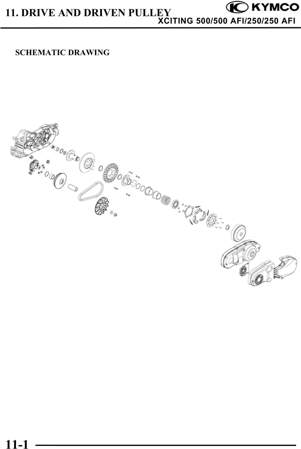
1 11 DRIVE AND DRIVEN PULLEY SCHEMATIC DRAWING SERVICE INFORMATION TROUBLESHOOTING LEFT CRANKCASE COVER DRIVE PULLEY CLUTCH/DRIVEN PULLEY

2 SCHEMATIC DRAWING 11-1
3 SERVICE INFORMATION GENERAL INSTRUCTIONS The drive pulley, clutch and driven pulley can be serviced with the engine installed. Avoid getting grease and oil on the drive belt and pulley faces. Remove any oil or grease from them to minimize the slipping of drive belt and drive pulley. Do not apply grease to the movable drive face and weight rollers. SPECIFICATIONS (XCITING 500/500 AFI) Unit: mm (in) Item Standard Service Limit Movable driven face bushing I.D. 48 (1.92) (1.921) (1.9224) Driven face collar O.D (1.9186) (1.9194) (1.9176) Drive belt width 28.9 (1.156) 27.9 (1.116) Clutch lining thickness 4 (0.16) 1 (0.04) Clutch outer I.D. 160 (6.3) (6.31) (6.32) Drive pulley collar O.D (1.158) (1.159) 28.9 (1.156) Weight roller O.D (1.1992) (1.203) 29.5 (1.18) SPECIFICATIONS (XCITING 250/250 AFI) Unit: mm (in) Item Standard Service Limit Movable driven face bushing I.D. 40 (1.6) (1.601) (1.6024) Driven face collar O.D (1.5986) (1.5994) (1.5976) Drive belt width 23.6 (0.944) 24.4 (0.976) 22 (0.88) Clutch lining thickness 4 (0.16) 1 (0.04) Clutch outer I.D. 153 (6.12) (6.128) (6.14) Drive pulley collar O.D (1.0784) ( ) 26.9 (1.076) Weight roller O.D (0.9168) (0.9232) 22 (0.88) 11-2
 47.94 (1.9176) Drive belt width 28.9 (1.156) 27.9 (1.116) Clutch lining thickness 4 (0.16) 1 (0.04) Clutch outer I.D. 160 (6.3) 160.2 (6.31) 160.5 (6.32) Drive pulley collar O.D. 28.96 (1.")
4 TORQUE VALUES (XCITING 500/500 AFI) Drive face nut 135 N m (13.5 kgf m, 97 lbf ft) Apply oil to the threads Clutch outer nut 80 N m (8 kgf m, 58 lbf ft) Clutch drive plate nut 78 N m (7.8 kgf m, 56 lbf ft) TORQUE VALUES (XCITING 250/250 AFI) Drive face nut 93 N m (9.3 kgf m, 67 lbf ft) Apply oil to the threads Clutch outer nut 54 N m (5.4 kgf m, 39 lbf ft) Clutch drive plate nut 54 N m (5.4 kgf m, 39 lbf ft) SPECIAL TOOLS (XCITING 500/500 AFI) Universal holder A120E00017 Clutch spring compressor A120E00053 Oil seal & bearing install A120E00014 SPECIAL TOOLS (XCITING 250/250 AFI) Universal holder A120E00017 Clutch spring compressor A120E00034 Oil seal & bearing install A120E00014 TROUBLESHOOTING Engine starts but motorcycle won t move Worn drive belt Broken ramp plate Worn or damaged clutch lining Broken driven face spring Lack of power Worn drive belt Weak driven face spring Worn weight roller Faulty driven face Engine stalls or motorcycle creeps Broken clutch weight spring 11-3
 SPECIAL TOOLS (XCITING 500/500 AFI) Universal holder A120E00017 Clutch spring compressor A120E00053 Oil seal & bearing install A120E00014 SPECIAL TOOLS (XCITING 250/250 AFI)")
5 LEFT CRANKCASE COVER REMOVAL (XCITING 500/500 AFI) Remove the left center body cover (page 2-5). Bolts Remove the three bolts and the left front cover.. Left Front Cover Remove the two bolts and left rear cover Bolts Left Rear Cover Remove the eight bolts and left crankcase cover. Bolts Crankcase 11-4

6 Remove the dowel pins and gasket. Dowel Pins Gasket REMOVAL (XCITING 250/250 AFI) Remove the left crankcase cover bolts and left crankcase covers. Bolts Left Crankcase Cover Remove the seal rubber and dowel pins. Dowel Pins Seal Rubber 11-5

7 DRIVESHAFT BEARING REPLACEMENT (XCITING 500/500 AFI) Remove the snap ring. Clip Heat the left crankcase cover around the driveshaft bearing with industrial dryer. Remove the driveshaft bearing from the left crankcase cover. Industrial Dryer Bearing Install the new driveshaft bearing into the left crankcase cover using a special tool. Special tool: Oil seal & bearing install A120E00014 INSTALLATION Installation is in the reverse order of removal. Clean the gasket on the left crankcase before installation. Bearing Install 11-6

8 DRIVE PULLEY REMOVAL Remove the left crankcase cover (XCITING 500/500 AFI: page 11-4, XCITING 250/250 AFI: 11-5). Hold the drive pulley face with the special tool and loosen the drive pulley face nut. Nut/Washer Drive Pulley Face Special tool: Universal holder A120E00017 Remove the nut, washer and drive pulley face. Universal Holder Hold the clutch outer with the special tool as shown. Nut/Collar (XCITING 500/500 AFI) Clutch Outer Special tool: Universal holder A120E00017 Remove the nut, collar (XCITING 500/500 AFI) and clutch outer. Universal Holder Remove the clutch/driven pulley assembly and drive belt. Drive Belt Clutch/Driven Pulley 11-7

9 Remove the washer (XCITING 500/500 AFI). Washer (XCITING 500/500 AFI) Remove the movable drive face assembly while holding the back of the face (ramp plate). Drive Face Boss Movable Drive Face Remove the washer (XCITING 500/500 AFI). Washer (XCITING 500/500 AFI) 11-8
")
10 DISASSEMBLY Drive pulley Remove the ramp plate and slide pieces. Ramp Plate Slide Pieces Remove the weight rollers. Weight Rollers Remove the drive face boss from the movable drive face. Drive Face Boss 11-9

11 INSPECTION Movable Drive Face Check the drive face boss for wear or damage. Measure the boss O.D.. Service limit: XCITING 500/500 AFI: 28.9 mm (1.156 in) XCITING 250/250 AFI: 26.9 mm (1.076 in) Measure the face bushing I.D.. Service limit: XCITING 500/500 AFI: 29.1 mm (1.164 in) XCITING 250/250 AFI: mm (1.058 in) Weight Roller Check each roller for wear or damage. Measure the weight roller O.D.. Service limit: XCITING 500/500 AFI: 29.5 mm (1.18 in) XCITING 250/250 AFI: 22 mm (0.888 in) Dust Seal Movable Drive Face Check the dust seal (XCITING 500/500 AFI) for wear or damage
 XCITING 250/250 AFI: 22 mm (0.")
12 ASSEMBLY Clean any oil and grease from the pulley faces and weight rollers. Drive Face Boss Install the drive face boss into the movable drive face. Install the weight rollers to the movable drive face. The direction of all weight rolls is the same. The thin side is towards to clockwise. Weight Rollers Thin Side Install the slide pieces to ramp plate. Install the ramp plate to the movable drive face. Ramp Plate Slide Pieces 11-11

13 INSTALLATION Install the washer (XCITING 500/500 AFI). The inner indentation side on the washer faces the left crankcase. Inner Indentation Side (XCITING 500/500 AFI) Washer Clean any oil and grease from the pulley faces and the drive belt. Washer (XCITING 500/500 AFI) Install the movable drive face assembly onto the crankshaft while holding the ramp plate. Install the washer (XCITING 500/500 AFI). Movable Drive Face Assembly Drive Belt Install the drive belt and clutch/driven pulley assembly. Install the drive belt with the arrow mark facing the direction of travel. Clutch/Driven Pulley Assembly 11-12
. Movable Drive Face Assembly Drive Belt Install the drive belt and clutch/driven pulley assembly.")
14 Hold the clutch outer with the special tool as shown. Clutch Outer Collar (XCITING 500/500 AFI)/Nut Special tool: Universal holder A120E00017 Install the collar (XCITING 500/500 AFI) and nut. Tighten the nut to the specified torque. Torque: XCITING 500/500 AFI: 80 N m (8 kgf m, 58 lbf ft) XCITING 250/250 AFI: 54 N m (5.4 kgf m, 36 lbf ft) Universal Holder Install the drive pulley face and washer. Apply oil to the drive pulley face nut threads and seating surface and install the nut. Hold the drive face with the special tool and tighten the bolt to the specified torque. Washer/Nut Drive Pulley Face Special tool: Universal holder A120E00017 Torque: XCITING 500/500 AFI: 135 N m (13.5 kgf m, 97 lbf ft) XCITING 250/250 AFI: 93 N m (9.3 kgf m, 67 lbf ft) Universal Holder 11-13

15 CLUTCH/DRIVEN PULLEY REMOVAL Remove the left crankcase cover (XCITING 500/500 AFI: page 11-4, XCITING 250/250 AFI: 11-5). Hold the drive pulley face with the special tool and loosen the drive pulley face nut. Special tool: Universal holder A120E00017 Remove the nut, washer and drive pulley face. Nut/Washer Drive Pulley Face Universal Holder Hold the clutch outer with the special tool as shown. Nut/Collar (XCITING 500/500 AFI) Clutch Outer Special tool: Universal holder A120E00017 Remove the nut, collar (XCITING 500/500 AFI) and clutch outer. Universal Holder Remove the clutch/driven pulley assembly and drive belt. Drive Belt Clutch/Driven Pulley 11-14

16 DISASSEMBLY Clutch/Driven Pulley Hold the clutch/driven pulley assembly with the clutch spring compressor. Be sure to use a clutch spring compressor to avoid spring damage. Lock Nut Wrench Special tool: XCITING 500/500 AFI: Clutch Spring Compressor XCITING 250/250 AFI: Clutch Spring Compressor A120E00053 A120E00034 Set the tool in a vise and remove the clutch drive plate nut. Clutch spring compressor Remove the spring compressor and disassemble the following: - Clutch assembly - Driven face spring - Driven pulley Driven Face Spring Remove the washer (XCITING 500/500 AFI). Washer (XCITING 500/500 AFI) Remove the spring collar (XCITING 500/500 AFI). Remove the seal collar Spring Collar (XCITING 500/500 AFI) Seal Collar

17 Remove the guide roller pins, guide rollers and the movable driven face. Movable Driven Face Guide Roller Pins/Guide Rollers Remove the O-rings and oil seals from the movable driven face. Oil Seals O-rings Driven Face Bearing Replacement Remove the driven face needle bearing. Remove the snap ring, then remove the ball bearing. Snap Ring Needle Bearing Apply grease to new ball bearing. Install the ball bearing into the driven face. Install the snap ring to groove in the driven face securely. Ball Bearing 11-16

18 Filling 25 g of grease to the driven face inner surface. Needle Bearing Apply grease to new needle bearing. Press the needle bearing into the driven. Grease INSPECTION Clutch Outer Check the clutch outer for wear or damage. Measure the clutch outer I.D.. Service limit: XCITING 500/500 AFI: mm (6.32 in) XCITING 250/250 AFI: mm (6.14 in) Clutch Shoe Lining Check the clutch shoe for wear or damage. Measure the thickness of each shoe. Service limit: 1 mm (0.04 in) 11-17
 XCITING 250/250 AFI: 153.5 mm (6.14 in) Clutch Shoe Lining Check the clutch shoe for wear or damage.")
19 Driven Face Spring Measure the driven face spring free length. Service limit: XCITING 500/500 AFI: mm (4.028 in) XCITING 250/250 AFI: mm (5.22 in) Driven Face Check the driven face for scratches, scoring or damage. Measure the driven face boss O.D.. Service limit: XCITING 500/500 AFI: mm ( in) XCITING 250/250 AFI: mm ( in) Movable Driven Face Check the movable driven face for scratches, scoring or damage. Check the guide grooves for stepped wear or damage. Measure the movable driven face I.D.. Service limit: XCITING 500/500 AFI: mm ( in) XCITING 250/250 AFI: mm ( in) 11-18

20 Drive Belt Check the drive belt for cracks, separation or abnormal or excessive wear. Attach the suitable plates ad shown. Measure the drive belt width. Service limit: XCITING 500/500 AFI: 27.9 mm (1.116 in) XCITING 250/250 AFI: 22 mm (0.88 in) Remove the clutch/driven pulley, then replace the drive belt if necessary. ASSEMBLY Clean any oil from the drive belt sliding surfaces on the driven face. Oil Seals Apply grease to new oil seal lips and install into the movable driven face. Coat new O-rings with grease and install them into the movable driven face grooves. O-rings 11-19

21 Install the movable driven face onto the driven face. Install the guide rollers and guide roller pins. Filling 8 g of grease to each guide groove. Grease Install the seal collar. Install spring collar (XCITING 500/500 AFI). Install washer (XCITING 500/500 AFI). Install driven face spring. Driven Face Spring Install the drive belt into the driven pulley. Squeeze and hold the drive belt by your hand. Set the clutch spring compressor over the clutch/driven pulley assembly and hold the spring compressor in a vice. Washer Lock Nut Wrench Special tool: XCITING 500/500 AFI: Clutch Spring Compressor XCITING 500/500 AFI: Clutch Spring Compressor A120E00053 A120E00034 Compress the driven face spring. Install and tighten the clutch drive plate nut to the specified torque. Torque: XCITING 500/500 AFI: 78 N m (7.8 kgf m, 56 lbf ft) XCITING 250/250 AFI: 54 N m (5.4 kgf m, 39 lbf ft) Clutch spring compressor 11-20
22 Install the drive belt with the arrow mark facing the direction of travel. Drive Belt Install the drive belt and clutch/driven pulley assembly. Clutch/Driven Pulley Assembly Hold the clutch outer with the special tool as shown. Nut/Collar Clutch Outer Special tool: Universal holder A120E00017 Install the collar and nut. Tighten the nut to the specified torque. Torque: XCITING 500/500 AFI: 80 N m (8 kgf m, 58 lbf ft) XCITING 250/250 AFI: 54 N m (5.4 kgf m, 39 lbf ft) Universal Holder Install the drive pulley face and washer. Apply oil to the drive pulley face nut threads and seating surface and install the nut. Hold the drive face with the special tool and tighten the bolt to the specified torque. Washer/Nut Drive Pulley Face Special tool: Universal holder A120E00017 Torque: XCITING 500/500 AFI: 135 N m (13.5 kgf m, 97 lbf ft) XCITING 250/250 AFI: 93 N m (9.3 kgf m, 67 lbf ft) Universal Holder
12. REAR WHEEL/BRAKE/SUSPENSION
 12 12 12-0 SERVICE INFORMATION... 12-1 REAR BRAKE... 12-5 TROUBLESHOOTING... 12-2 REAR SHOCK ABSORBER... 12-8 REAR WHEEL... 12-3 REAR FORK... 12-9 SERVICE INFORMATION GENERAL INSTRUCTIONS When installing
Unit: mm(in) Item Standard value Service limit Axle shaft run out - 0.2(0.008)
 Item Standard value Service limit Axle shaft run out - 0.2(0.008)") Rear Wheel/Brake/Suspension 13. Rear Wheel/Brake/Suspension Service Information 13-1 Troubleshooting 13-2 Rear Wheel 13-3 Rear Cushion 13-4 Rear Swing Arm 13-7 Service Information General Safety If the
Rear Wheel/Brake/Suspension 13. Rear Wheel/Brake/Suspension Service Information 13-1 Troubleshooting 13-2 Rear Wheel 13-3 Rear Cushion 13-4 Rear Swing Arm 13-7 Service Information General Safety If the
13. REAR WHEEL/BRAKE/SUSPENSION
 13. REAR WHEEL/BRAKE/SUSPENSION 13 3.5~4.5kg-m 8.0~10.0kg-m 0.8~1.2kg-m 3.0~4.0kg-m 2.4~3.0kg-m 3.5~4.5kg-m 6.0~8.0kg-m 13-0 13. REAR WHEEL/BRAKE/SUSPENSION 13 REAR WHEEL/BRAKE/SUSPENSION SERVICE INFORMATION...
STEERING HANDLEBAR/FRONT WHEEL/ FRONT SHOCK ABSORBER
 14 14 STEERING HANDLEBAR/FRONT WHEEL/ SCHEMATIC DRAWING ------------------------------------------------- 14-1 SERVICE INFORMATION------------------------------------------------ 14-2 TROUBLESHOOTING-----------------------------------------------------
C O N T E N T S 1 ABOUT THIS PARTS LIST... 2 ENGINE GROUP... 3 3 CONTENTS-FRAME GROUP
 C O N T E N T S 1 ABOUT THIS PARTS LIST... 2 2 CONTENTS-ENGINE ENGINE GROUP ENGINE GROUP... 3 3 CONTENTS-FRAME GROUP FRAME GROUP... 5 4 ENGINE PARTS LIST... 9 5 FRAME PARTS LIST...37 1 ABOUT THIS PARTS
Parts#MB003-003 Reverse Gear MAMBA (Monoblock for Cable operated) For 5 speed Trans., '87 to '06 Big Twin models (except '06 Dyna)
 For 5 speed Trans., '87 to '06 Big Twin models (except '06 Dyna)") Installation Instructions Reverse Gear MAMBA (Monoblock for Cable operated) Read and become familiar with these installation instructions before start. Two Piece for H-D 5 Speed Trans., Cable operated
Installation Instructions Reverse Gear MAMBA (Monoblock for Cable operated) Read and become familiar with these installation instructions before start. Two Piece for H-D 5 Speed Trans., Cable operated
STEERING SYSTEM - POWER
 STEERING SYSTEM - POWER 1990 Nissan 240SX 1990 STEERING Nissan - Power Rack & Pinion Axxess, Maxima, Pulsar NX, Sentra, Stanza, 240SX, 300ZX DESCRIPTION The power steering system consists of a rack and
Drive shaft, servicing
 Volkswagen Passat B6 - Drive shaft, servicing Стр. 1 из 41 40-7 Drive shaft, servicing Drive shafts, overview I - Assembly overview: Drive axle with CV joint VL100 40-7, Drive axle with CV joint VL100,
Cylinder head, removing and replacing
 15-1 Cylinder head, removing and replacing WARNING! Do not re-use any fasteners that are worn or deformed in normal use. Some fasteners are designed to be used only once, and are unreliable and may fail
Rebuild Instructions for 70001 and 70010 Transmission
 Rebuild Instructions for 70001 and 70010 Transmission Brinn, Incorporated 1615 Tech Drive Bay City, MI 48706 Telephone 989.686.8920 Fax 989.686.6520 www.brinninc.com Notice Read all instructions before
ENGINE FUEL FUEL FILTER... FUEL HEATER... INJECTOR... SUPPLY PUMP... COMMON RAIL... FUEL PRESSURE LIMITTER...
 FUEL FILTER............................ FUEL HEATER.......................... INJECTOR.............................. SUPPLY PUMP.......................... COMMON RAIL.......................... FUEL PRESSURE
ARTICLE BEGINNING APPLICATION IDENTIFICATION DESCRIPTION LUBRICATION & ADJUSTMENT TROUBLE SHOOTING. MANUAL TRANSMISSIONS Saab 5-Speed Transaxle
 Article Text ARTICLE BEGINNING MANUAL TRANSMISSIONS Saab 5-Speed Transaxle APPLICATION TRANSMISSION APPLICATION ÄÄÄÄÄÄÄÄÄÄÄÄÄÄÄÄÄÄÄÄÄÄÄÄÄÄÄÄÄÄÄÄÄÄÄÄÄÄÄÄÄÄÄÄÄÄÄÄÄÄÄÄÄÄÄÄÄÄÄÄ Vehicle Application Transmission
AXLE SHAFTS - FRONT. 1998 Pontiac Bonneville MODEL IDENTIFICATION DESCRIPTION & OPERATION TROUBLE SHOOTING REMOVAL & INSTALLATION
 AXLE SHAFTS - FRONT 1998 Pontiac Bonneville 1998-99 DRIVE AXLES FWD Axle Shafts - Cars - "C", "G" & "H" Bodies GM Aurora, Bonneville, Eighty Eight, LeSabre, LSS, Park Avenue, Regency, Riviera MODEL IDENTIFICATION
ASSEMBLY DIAGRAM AND ASSEMBLY REFERENCE ULTIMA OLD SCHOOL 2 EVO & TC BELT DRIVE UNITS
 ASSEMBLY DIAGRAM AND ASSEMBLY REFERENCE ULTIMA OLD SCHOOL 2 EVO & TC BELT DRIVE UNITS BELT DRIVE ASSEMBLIES Part# 58-850 2 Old School Belt Drive Assembly - Polished Part# 58-851 2 Old School Belt Drive
TABLE OF CONTENTS. iii
 TABLE OF CONTENTS GENERAL INFORMATION 1 PERIODIC MAINTENANCE AND TUNE-UP PROCEDURES 5 ENGINE 9 LUBRICATION SYSTEM 24 FUEL SUPPLY SYSTEM 28 TRANSMISSION COMPONENTS 33 ELECTRICAL STARTING SYSTEM 36 BELT
DO NOT attempt to repair hub and wheel bearing assembly.
 Page 1 of 6 HUB & WHEEL BEARINGS (WITH PULSE VACUUM HUBLOCK) DO NOT attempt to repair hub and wheel bearing assembly. Removal DO NOT remove hub lock assembly by prying on hub lock legs. This can crack
Volkswagen Jetta, Golf, GTI 1999, 2000 Brake System 46 Brakes - Mechanical Components (Page GR-46)
") 46 Brakes - Mechanical Components (Page GR-46) Front brakes Brake pads, removing and installing Brake pads, removing and installing FN 3 brake caliper, servicing FS III brake caliper, servicing Rear wheel
46 Brakes - Mechanical Components (Page GR-46) Front brakes Brake pads, removing and installing Brake pads, removing and installing FN 3 brake caliper, servicing FS III brake caliper, servicing Rear wheel
MANUAL TRANSMISSION CONTENTS ...
 22D-0-1 MANUAL TRANSMISSION CONTENTS GENERAL INFORMATION... 22D-0-3 1. SPECIFICATIONS... 22D-1-1 TRANSMISSION MODEL TABLE GENERAL SPECIFICATIONS SERVICE SPECIFICATIONS TORQUE SPECIFICATIONS............
The Crankshaft Oil Seal Section has been added to the DD15 Workshop Manual. The sections that are found in the Engine Chapter are now renumbered.
 NUMBER: 08 DD15-5 S.M. REF.: 1.11 ENGINE: DD15 DATE: July 2008 SUBJECT: CRANKSHAFT OIL SEAL SECTION PUBLICATION: DDC-SVC-MAN-0002 The Crankshaft Oil Seal Section has been added to the DD15 Workshop Manual.
Char-Lynn Hydraulic Motor. Repair Information. 10 000 Series. October, 1997
 Char-Lynn Hydraulic Motor October, 1997 Repair Information Geroler Motor Two Speed 001 27 Retainer inside bore of valve plate bearingless motors only 4 15 16 3 6 35 Parts Drawing 25 2 2 1 19 17 36 40 47
Volkswagen Jetta, Golf, GTI 1999, 2000 Brake System 47 Brakes - Hydraulic Components (Page GR-47)
") 47 Brakes - Hydraulic Components (Page GR-47) FS III front brake calipers, servicing Front brake caliper piston, removing and installing FN 3 front brake calipers, servicing Front caliper piston, removing
47 Brakes - Hydraulic Components (Page GR-47) FS III front brake calipers, servicing Front brake caliper piston, removing and installing FN 3 front brake calipers, servicing Front caliper piston, removing
Front brakes (FN- 3), servicing
, servicing") j a t Front brakes (FN- 3), servicing 46-1 Front brakes, servicing Note: Install complete repair kit. After replacing brake pads and before moving vehicle, depress brake pedal several times firmly to properly
j a t Front brakes (FN- 3), servicing 46-1 Front brakes, servicing Note: Install complete repair kit. After replacing brake pads and before moving vehicle, depress brake pedal several times firmly to properly
CAM-03, Camshaft Assembly Oil Seal Replacement
 CAM-03, Camshaft Assembly Oil Seal Replacement Tools Jack stands Floor Jack Metric Socket set Metric Wrench set Porsche Timing Belt Tension tool (P9201) Flywheel Lock (P9206) Balance Shaft Pin Spanner
2008 ACCORD - Front Knuckle/Hub/Wheel Bearing Replacement (page 18-13)
") 2008 ACCORD - Front Knuckle/Hub/Wheel Bearing Replacement (page 18-13) Exploded View Special Tools Required Ball joint remover, 28 mm 07MAC-SL0A202 Hub dis/assembly tool 07GAF-SD40100 Bearing driver attachment,
2008 ACCORD - Front Knuckle/Hub/Wheel Bearing Replacement (page 18-13) Exploded View Special Tools Required Ball joint remover, 28 mm 07MAC-SL0A202 Hub dis/assembly tool 07GAF-SD40100 Bearing driver attachment,
This is the civilian transfer case with the cooling loop only found in the driven gear half of the front case.
 INTRODUCTION The Transfer case used in the AMG Hummer is a New Venture Gear, model 242. This case has been in use for the H-1/Hummer since the early 1990 s. There have been modifications to the internal
3000, 4000, 4100, 7500, 7700
 3000, 4000, 4100, 7500, 7700 Drum & Disc Brake Lathes s Identification READ these instructions before placing unit in service. KEEP these and other materials delivered with the unit in a binder near the
For exploded diagram and part number information, refer to the Spare Parts Catalog available on our website at www.rockshox.com.
 For exploded diagram and part number information, refer to the Spare Parts Catalog available on our website at www.rockshox.com. Information contained in this publication is subject to change at anytime
2003 Audi A4. AUDI' '3.0L V6 - AVK Engine - A4 & A6
 Installation (A4) CAUTION: Before installation, ensure camshafts are aligned, crankshaft is locked in place and camshaft gear bolts are loose as described in removal procedures. When turning camshaft,
1.8 CRANKSHAFT OIL SEALS
 SERIES 60 SERVICE MANUAL 1.8 CRANKSHAFT OIL SEALS An oil seal is fitted between each end of the crankshaft and the bores of the flywheel housing and gear case cover to retain the lubricating oil in the
1/29/2008 DR70. Baja Motorsports Inc. P.O. Box 61150 Phoenix, AZ 85082 Toll Free: 888-863-2252 PART NUMBERS PRICES ARE SUBJECT TO CHANGE 1 of 43
 DR70 Toll Free: 888-863-2252 PART NUMBERS PRICES ARE SUBJECT TO CHANGE 1 of 43 CYLINDER & CYLINDER HEAD 1 DR70-001 883099044472 CYLINDER 1 1 2 DR70-002 883099044489 GASKET, CYLINDER 1 1 3 DR70-003 883099044496
INDEX INTRODUCTION. Reference No. 10-21L-01 R E V I S E D : 2 0 0 5 0 2
 10-21L-01 SRM-2305, SRM-2305SI 1 1 INTRODUCTION We are constantly working on technical improvement of our products. For this reason, technical data, equipment and design are subject to change without notice.
Pallet Jack. OWNER S MANUAL Model MH1230. Important Safety Instructions Assembly Instructions Parts and Hardware Identification
 OWNER S MANUAL Model MH1230 Important Safety Instructions Assembly Instructions Parts and Hardware Identification Pallet Jack CAUTION: Read, understand and follow ALL instructions before using this product
Round Housing with Side Ports
 Power Steering Steering Control Unit (SCU) Parts and Repair Information 5 Series Steering Control Units 001 Square Housing with Side Ports Round Housing with Side Ports T E L RP Round Housing with End
SCION tc 2005-2008 COIL OVER SUSPENSION Preparation
 SCION tc 2005-2008 COIL OVER SUSPENSION Preparation Part Number: PTR11-21070 NOTE: Part number of this accessory may not be the same as the part number shown. Kit Contents: Item # Quantity Reqd. Description
Fire Hydrant Troubleshooting
 Fire Hydrant Troubleshooting Pulsation or chatter during opening and flow of water from hydrant. Loose condition in stem at lower valve plate nut. Tighten lower valve plate nut and secure with SS lock
DR50 Hensim Dirt Runner 49cc Dirt Bike (VIN PREFIX LLCH or LUAH)
") Page 1 of 21 Product Information Baja Web > Product Information > Parts Lists > DIRTBIKE > DR50 Hensim Dirt Runner 49cc Dirt Bike (VIN PREFIX LLCH or LUAH) DR50 Hensim Dirt Runner 49cc Dirt Bike (VIN PREFIX
Page 1 of 21 Product Information Baja Web > Product Information > Parts Lists > DIRTBIKE > DR50 Hensim Dirt Runner 49cc Dirt Bike (VIN PREFIX LLCH or LUAH) DR50 Hensim Dirt Runner 49cc Dirt Bike (VIN PREFIX
11. COOLING SYSTEM 11-0 COOLING SYSTEM BET & WIN 50
 11 COOLING SYSTEM SERVICE INFORMATION------------------------------------------------ 11-1 TROUBLESHOOTING----------------------------------------------------- 11-1 RADIATOR ------------------------------------------------------------------
Table of Contents. Overview 1. Pump Disassembly 2. Control Disassembly / Reassembly 7. Pump Reassembly 13. Adjustment Procedures DR Control 19
 Table of Contents Overview 1 Pump Disassembly 2 Control Disassembly / Reassembly 7 Pump Reassembly 13 Adjustment Procedures DR Control 19 Adjustment Procedures DRG Control 20 Adjustment Procedures DFR
CYLINDER HEAD (4A FE)
") EM81 CYLINDER HEAD (4AFE) COMPONENTS EM82 ENGINE MECHANICAL REMOVAL OF CYLINDER HEAD (See page EM81) 1. DISCONNECT CABLE FROM NEGATIVE TERMINAL OF BATTERY CAUTION: Work must be started after approx. 20
EM81 CYLINDER HEAD (4AFE) COMPONENTS EM82 ENGINE MECHANICAL REMOVAL OF CYLINDER HEAD (See page EM81) 1. DISCONNECT CABLE FROM NEGATIVE TERMINAL OF BATTERY CAUTION: Work must be started after approx. 20
DIFFERENTIAL AND DRIVELINE
 PL DIFFERENTIAL AND DRIVELINE 3-1 DIFFERENTIAL AND DRIVELINE TABLE OF CONTENTS page DESCRIPTION AND OPERATION FRONT DRIVESHAFTS...1 DIAGNOSIS AND TESTING DRIVESHAFT DIAGNOSIS....2 REMOVAL AND INSTALLATION
DANA 30 MANUAL HUB CONVERSION KIT
 DANA 30 MANUAL HUB CONVERSION KIT 12194 PLEASE READ AND UNDERSTAND ALL INSTRUCTIONS BEFORE YOU BEGIN Your safety and the safety of other motorists is very important. Your Jeep is an off road capable vehicle
2006 HEADSHOK Service Video #1
 LEFTY SPEED DLR DAMPING CARTRIDGE This document explains how to properly remove, disassemble, inspect, reassemble and reinstall the Lefty Speed DLR2 damping cartridge. It is a document to be used in conjunction
SERVICE PARTS LIST PAGE 1 OF 6 BASE ASSEMBLY SPECIFY CATALOG NO. AND SERIAL NO. WHEN ORDERING PARTS 12" DUAL BEVEL COMPOUND MITER SAW B27A
 PAGE 1 OF 6 BASE ASSEMBLY 00 0 EXAMPLE: Component Parts (Small #) Are Included When Ordering The Assembly (Large #). SPECIFY CATALOG NO. AND NO. WHEN ORDERING PARTS 1 02-80-0050 Thrust Bearing (1) 2 05-80-0510
Engine, disassembling and assembling
 13-1 Engine, disassembling and assembling Note: Replace the oil cooler and thoroughly clean the oil passages if you find metal shavings or larger quantities of small metal particles in the engine oil,
1993 SUSPENSION Volkswagen Front. EuroVan
 Article Text ARTICLE BEGINNING 1993 SUSPENSION Volkswagen Front EuroVan DESCRIPTION FWD independent suspension is an double-wishbone type with torsion bars mounted on upper control arm. Wheel is supported
DR90. Baja Motorsports Inc. P.O. Box 61150 Phoenix, AZ 85082 Toll Free: 888-863-2252 PART NUMBERS AND PRICES ARE SUBJECT TO CHANGE 1 of 51
 DR90 Toll Free: 888-863-2252 PART NUMBERS AND PRICES ARE SUBJECT TO CHANGE 1 of 51 CYLINDER & CYLINDER HEAD 1 DR90-001 842645048166 CYLINDER 1 1 2 DR90-002 842645048173 GASKET, CYLINDER 1 1 3 DR90-003
DiscPlus DX195 and DX225 Air Disc Brakes
 Revised 11-04 Technical Bulletin Revised 1 Technical 11-04 Bulletin DiscPlus DX195 and DX225 Air Disc Brakes Inspection, Installation and Diagnostics Air Disc Brake Inspection Intervals and Procedures
PRINCE 50 Parti di ricambio agg. al 30-11-09
 . 缸 头 罩 部 件 CYLINDER HEAD COVER(FOR EUROPE) 50000 COVER COMP HEAD 2 5000 GASKET HEAD COVER 3 50002 Aeration Head Cover 4 50372 AERATION CAP 5 50355 TUBE BREATHER 6 50356 TIE-IN 7 50358 AERATION TUBE ASSY
DR125 and DR150 Hensim Dirt Runner 125cc and 150cc Dirt Bike (VIN PREFIX LLCH or LUAH)
") Parts Lists - DR125 and DR150 Hensim Dirt Runner 125cc and 150cc Dirt Bike (VIN PR... Page 1 of 25 Product Information Baja Web > Product Information > Parts Lists > DIRTBIKE > DR125 and DR150 Hensim Dirt
Parts Lists - DR125 and DR150 Hensim Dirt Runner 125cc and 150cc Dirt Bike (VIN PR... Page 1 of 25 Product Information Baja Web > Product Information > Parts Lists > DIRTBIKE > DR125 and DR150 Hensim Dirt
Volkswagen B3 Passat Manual Transmission 02A 34 Manual Transmission - Controls, Assembly (Page GR-34) 02A 5-speed. Gearshift cable/lever installing
 02A 5-speed. Gearshift cable/lever installing") 34 Manual Transmission - Controls, Assembly (Page GR-34) 02A 5-speed Gearshift cable/lever installing Gearshift housing repairing Gearshift lever repairing lever/relay lever, installing Gearshift mechanism
34 Manual Transmission - Controls, Assembly (Page GR-34) 02A 5-speed Gearshift cable/lever installing Gearshift housing repairing Gearshift lever repairing lever/relay lever, installing Gearshift mechanism
2003-2004 SID REAR SERVICE GUIDE
 2003-2004 SID REAR SERVICE GUIDE For exploded diagram and part number information, refer to the Spare Parts Catalog available on our website at www.rockshox.com. Contact your local distributor or visit
HYBRID CAM PLATE AND HIGH VOLUME OIL PUMP KIT
 -J056 REV. 0-05-0 HYBRID CAM PLATE AND HIGH VOLUME OIL PUMP KIT GENERAL Kit Number 584- Models For model fitment information, see the P&A retail catalog or the Parts and Accessories section of www.harley-davidson.com
BR150 Pmi Baja Reaction 150cc Go Kart (VIN PREFIX L4VM)
") Page 1 of 21 Product Information Baja Web > Product Information > Parts Lists > GOKART > BR150 Pmi Baja Reaction 150cc Go Kart (VIN PREFIX L4VM) BR150 Pmi Baja Reaction 150cc Go Kart (VIN PREFIX L4VM)
Page 1 of 21 Product Information Baja Web > Product Information > Parts Lists > GOKART > BR150 Pmi Baja Reaction 150cc Go Kart (VIN PREFIX L4VM) BR150 Pmi Baja Reaction 150cc Go Kart (VIN PREFIX L4VM)
BSA Goldstar Parts - Price List April 2016. 65-1137 Exhaust Lifter Cable 15.00. 65-1163 Exhaust Lifter Cable Holder S/S 9.00
 Rocker Boxes 65-1137 Exhaust Lifter Cable 15.00 65-1163 Exhaust Lifter Cable Holder S/S 9.00 2-443 Exhaust Lifter Cable Holder Nut S/S 0.50 65-401 Exhaust Lifter Spindle Felt 2.00 65-387 Exhaust Lifter
Repair of Hyd-ro-ac Actuators
 Repair of Hyd-ro-ac Actuators OVERHAUL INSTRUCTIONS SS-.2A-1V SS-.5A-1V SS-.5A-2V Read the entire contents of these instructions before installing the actuator and before making any connections to the
MANUAL TRANS OVERHAUL - TYPE 02J Article Text 1999 Volkswagen Golf This file passed thru Volkswagen Technical Site -
 MANUAL TRANS OVERHAUL - TYPE 02J Article Text 1999 Volkswagen Golf This file passed thru Volkswagen Technical Site - http://volkswagen.msk.ru ARTICLE BEGINNING 1998-99 MANUAL TRANSMISSIONS Volkswagen/Audi
TUTORIAL. REbUILdING. front CALIpER O-RING CONVERSION CORVETTE 1965-82. Part #: HT-1
 Part #: HT-1 1965-82 CORVETTE O-RING CONVERSION front CALIpER REbUILdING TUTORIAL Choosing a Brake Caliper Rebuild Kit Standard Lip Seals vs. O-Ring Seals Lip seal design seals are used on 1965-1982 Corvette
2005 MINI Cooper. 2002-05 MANUAL TRANSMISSIONS On-Vehicle Servicing. Cooper S Getrag 285
 2002-05 MANUAL TRANSMISSIONS On-Vehicle Servicing APPLICATION MANUAL TRANSMISSION APPLICATIONS Application Transmission Model Cooper R65 Cooper S Getrag 285 LUBRICATION SERVICE INTERVALS Inspect fluid
Operating Instructions Parts List Manual Scissor Lift Pallet Truck
 Operating Instructions Parts List Manual Scissor Lift Pallet Truck Note: Operator MUST read and understand this operating instructions before use this Hand Scissor Lift. Thank you for using this hand scissors
INSTRUCTIONS. FLHR/C/S (Road King) FRONT END LOWERING KIT 1WARNING -J03242 REV. 10-19-04. General. Removal (Left and Right Forks) Kit Number 54614-05
 FRONT END LOWERING KIT 1WARNING -J03242 REV. 10-19-04. General. Removal (Left and Right Forks) Kit Number 54614-05") INSTRUCTIONS -J04 REV. 0-9-04 General FLHR/C/S (Road King) FRONT END LOWERING KIT This kit is designed for installation on 00 and later FLHR/C/S Model Motorcycles. Road King models use the conventional
INSTRUCTIONS -J04 REV. 0-9-04 General FLHR/C/S (Road King) FRONT END LOWERING KIT This kit is designed for installation on 00 and later FLHR/C/S Model Motorcycles. Road King models use the conventional
Number Wheeler P/N Description Set Rex P/N Notes
 1 604041 Base 1 4041 2 604042 Base Cover 1 4042 3 608849 Washer (M5) 2 4 600124 Spring Washer (M5) 2 5 600329 Rd Hd Machine Screw (M5x8) 2 6 604047 Strainer 1 4047 7 600204 Rd Hd Machine Screw (M6x10)
FRONT SUSPENSION Click on the applicable bookmark to selected the required model year
 FRONT SUSPENSION 33A-2 FRONT SUSPENSION General Information GENERAL INFORMATION 33200010105 The front suspension on 2WD vehicles is an independent suspension system having the double wishbone combined
INTRODUCTION KINGPIN REPLACEMENT
 KINGPIN REPLACEMENT Author: Randy Baumann All information, illustrations and specifications are based on the best information available at the time of publication. The author cannot guarantee the accuracy
Volkswagen New Beetle 2.0 Liter 4-cyl General, Engine (Engine Code AEG) 17 Engine-Lubrication system (Page GR-17)
 17 Engine-Lubrication system (Page GR-17)") 17 Engine-Lubrication system (Page GR-17) Lubrication system components, removing and installing Oil pan, removing and installing Oil pressure and oil pressure switch, checking Dynamic oil pressure warning
17 Engine-Lubrication system (Page GR-17) Lubrication system components, removing and installing Oil pan, removing and installing Oil pressure and oil pressure switch, checking Dynamic oil pressure warning
1/29/2008 DR125 / DR150. Baja Motorsports Inc. P.O. Box 61150 Phoenix, AZ 85082 Toll Free: 888-863-2252 PARTS AND PRICES ARE SUBJECT TO CHANGE 1 of 55
 DR125 / DR150 Toll Free: 888-863-2252 PARTS AND PRICES ARE SUBJECT TO CHANGE 1 of 55 CYLINDER HEAD ASSY. 1 125-001 883099006937 CYLINDER HEAD COVER 1 1 2 125-002 883099006944 BOLT M6X28 2 3 3 125-003 883099006951
STORAGE, INSTALLATION AND MAINTENANCE PROCEDURES
 GATE VALVE O.S. & Y 1.0 Periodic Inspections 1.1 The valve stem packing should be inspected at least monthly. If the stem packing shows signs of leakage, simply tighten the adjusting nuts to compress the
4 in 1 Strength Station
 Revision 0 September 2010 4 in 1 Strength Station Owner s Manual Record Serial Number Here Platinum by Tunturi www.tunturi.com Date www.tunturi.com of Purchase 4 in 1 Strength Station Owner s Manual Instructions
Front axle components, overview
 just a test. Front axle components, overview 40-1 General Information Load bearing components and parts of the suspension must not be welded or straightened. Vehicles without drive axle must not be moved,
SE-1200-EI. Operation & Parts Manual
 SE-1200-EI Operation & Parts Manual SE 1200 EI OWNERS MANUAL Table of Contents 1. Installation guide 2. Set-up instructions 3. Operation instructions 4. Cleaning 5. Troubleshooting 6. Parts manual 7. Electrical
WORKSHOP MANUAL 50CC ENGINE HORIZONTAL LIQUID-COOLED CYLINDER
 Sales division Technical network leadership WORKSHOP MANUAL 50CC ENGINE HORIZONTAL LIQUID-COOLED CYLINDER Sales division Technical network leadership TABLE OF CONTENTS TABLE OF CONTENTS TABLE OF CONTENTS...
Slide the new steering column shaft through the steering column from the driver compartment.
 Slide the new steering column shaft through the steering column from the driver compartment. Push the column shaft through the steering column until the machined end is out past the column lower bushing.
Atlas Front Input Change
 Atlas Front Input Change The following pages contain instructions for Atlas transfer case front input. Most mechanically inclined individuals can obtain the components from us and perform these retrofits
INSTALLATION and OPERATION RANGE BALL CONVEYOR MODEL NO: BC-001AN
 Easy Picker Golf Products, Inc. 415 Leonard Blvd. N., Lehigh Acres, FL 33971 PH: 239-368-6600 FAX: 239-369-1579 Service: 800-982-4653 SALES: 800-641-4653 www.easypicker.com [email protected] INSTALLATION
Number Wheeler P/N Description Set Rex P/N Notes 1 603500 Base 1 J001 2 603501 Support, Right 1 J002 3 603502 Support, Left 1 J003 4 600328 Nut (M8)
") 1 603500 Base 1 J001 2 603501 Support, Right 1 J002 3 603502 Support, Left 1 J003 4 600328 Nut (M8) 4 5 600130 Spring Washer (8mm) 4 6 600344 Roll Pin (M6x30) 4 7 600129 Socket Hd Cap Screw (M8x25) 4 8
1 603500 Base 1 J001 2 603501 Support, Right 1 J002 3 603502 Support, Left 1 J003 4 600328 Nut (M8) 4 5 600130 Spring Washer (8mm) 4 6 600344 Roll Pin (M6x30) 4 7 600129 Socket Hd Cap Screw (M8x25) 4 8
White Industries Rear Hub Instructions
 White Industries Rear Hub Instructions Tool required: 2mm allen/hex wrench, 19mm socket, 20mm socket, and mallet. 1. Loosen the set screws located in the adjusting collar by using a 2mm allen wrench inserted
ALLDATA Online - 2006 Dodge Truck RAM 2500 Truck 2WD L6-5.9L DSL Turbo VI... Service and Repair
 Page 1 of 15 Home Account Contact ALLDATA Log Out Help PAUL REDEHOFT Select Vehicle New TSBs Technician's Reference Component Search: OK 2006 Dodge Truck RAM 2500 Truck 2WD L6-5.9L DSL Turbo VIN C Conversion
TUTORIAL. REbUILdING. REAR CALIpER O-RING CONVERSION CORVETTE 1965-82. Part #: HT-2
 Part #: HT-2 1965-82 CORVETTE O-RING CONVERSION REAR CALIpER REbUILdING TUTORIAL Choosing a Brake Caliper Rebuild Kit Standard Lip Seals vs. O-Ring Seals Lip seal design seals are used on 1965-1982 Corvette
Rexroth. Spare parts list. Bosch Group. Part No.: R909401762 Designation: VERSTELLPUMPE A4V-125 HD
 : R909401762 : VERSTELLPUMPE A4V-125 HD *G* 1 R909400454 ROTARY GROUP L 2 R909414470 HYDRAULIC CONTROL L 3 R909080279 PORT PLATE WITH VALVES L 4 R909400395 INTERNAL GEAR PUMP L 6 R909401736 CONTROL MODULE
SE-900-MP ECO -SERIES. Operation & Parts Manual
 SE-900-MP ECO -SERIES Operation & Parts Manual SE 900 MP ECO - SERIES OWNERS MANUAL Table of Contents 1. Installation guide 2. Set-up instructions 3. Operation instructions 4. Cleaning 5. Troubleshooting
DR90. Baja Motorsports Inc. P.O. Box 61150 Phoenix, AZ 85082 Toll Free: 888-863-2252 PART NUMBERS AND PRICES ARE SUBJECT TO CHANGE 1 of 51
 DR90 Toll Free: 888-863-2252 PART NUMBERS AND PRICES ARE SUBJECT TO CHANGE 1 of 51 CYLINDER & CYLINDER HEAD Part UPC Number Description Baja Description 1 DR90-001 842645048166 CYLINDER 1 1 2 DR90-002
Char-Lynn Spool Valve Hydraulic Motors. Repair Information. W Series Geroler Motors
 Char-Lynn Spool Valve Hydraulic Motors Repair Information W Series Geroler Motors with Parking Brake 004 Nut Key Ring, Retaining Bearing Ring, Retaining Ring, Retaining Washer (Thick), Pressure Washer,
IF IT FLOWS THE BOWIE PUMP CAN PUMP IT
 IF IT FLOWS THE BOWIE PUMP CAN PUMP IT Bowie Industries, Inc. Bowie, TX 76230 USA Page 1 Bowie Pumps Manual General Pump Information..Page 2 300 Series Pumps.. Page 5 400 Series Pumps.Page 11 500 Series
SUPERCHIPPER CASTING MAINTENANCE
 INTRODUCTION By design, the Superchipper Rotor is clad in castings which wear during crushing. The castings wear at different rates depending on their location on the rotor, material feed rate, material
For exploded diagram and part number information, refer to the Spare Parts Catalog available on our website at www.rockshox.com.
 For exploded diagram and part number information, refer to the Spare Parts Catalog available on our website at www.rockshox.com. 2 0 0 5 D U K E A I R X C / S L / R A C E S E R V I C E G U I D E Information
2003 ACCORD - Automatic Transmission Removal
 2003 ACCORD - Automatic Transmission Removal Special Tools Required Engine support hanger, A and Reds AAR-T-12566 Engine hanger balancer bar VSB02C000019 Front subframe adapter VSB02C000016 These special
Service Manual Rol-Lift
 R 2000 Service Manual Rol-Lift Series: T and E Developed by Generic Parts Service This manual is intended for basic service and maintenance of the Rol-Lift pallet jack. The pallet jacks you are servicing
6-Speed Synchromesh Transmission Service Manual. (FS-6406 Series)
") 6-Speed Synchromesh Transmission Service Manual (FS-6406 Series) Issue 01/2003 Eaton 6-Speed Synchromesh Transmission Truck Components Operations Europe PO Box 11 Worsley Manchester M28 5GJ England Service
6-Speed Synchromesh Transmission Service Manual (FS-6406 Series) Issue 01/2003 Eaton 6-Speed Synchromesh Transmission Truck Components Operations Europe PO Box 11 Worsley Manchester M28 5GJ England Service
360 Automatic Chain Saw UT-10468 Page 1 of 15 Carburetor
 360 Automatic Chain Saw UT-10468 Page 1 of 15 Carburetor 360 Automatic Chain Saw UT-10468 Page 2 of 15 Carburetor 1 93205A 1 Repair Kit 2 93205A 1 Repair Kit 3 93205A 1 Repair Kit 4 93205A 1 Repair Kit
Tri-Homo Style Operation and Maintenance Instructions
 Tri-Homo Style Operation and Maintenance Instructions One Research Drive Stratford, CT 06615 (203) 375-0063 www.sonicmixing.com 1 Installation and Start-up Do not perform following adjustments without
TRS 090/105 Compressor. Repair Procedures
 TRS 090/105 Compressor Repair Procedures GENERAL FGG All repair and service operations should be performed on a clean bench and with the use of clean tools. Use genuine parts and correct tools for all
TRANS-05, Torque Tube Removal, Rebuilding, and Installation
 TRANS-05, Torque Tube Removal, Rebuilding, and Installation Tools Metric Wrench Set Metric Socket Set Jack Stands (6 minimum) Floor Jack 8mm Cheesehead socket (also referred to as 12 point internal socket
MAN - MERCEDES - BENZ
 SAYFA: 1 10100 10102 10103 355 353 06 15 355 353 03 15 346 353 08 15 AXLE GEAR AXLE GEAR AXLE (WITH BUSHING TYPE) (WITH BUSHING TYPE) (WITH BUSHING TYPE) 2521 2517-2521-2622 10104 10105 10106 308 350 00
Joplin Rebuild Instructions
 Joplin Rebuild Instructions This is a step by step list of instruction on how to rebuild the Crankbrothers Joplin post. It may not always be required to completely tear-down the post to do the work needed
TECHNICAL SERVICE MANUAL
 TECHNICAL SERVICE MANUAL HEAVY-DUTY PUMPS SERIES 4195 AND 495 SIZES GG - AL SECTION TSM 144 PAGE 1 of 10 ISSUE D CONTENTS Introduction....................... 1 Safety Information.................... 2
COOLING SYSTEM Section Page
 5 COOLING SYSTEM Section Page 5.1 COOLANT PRE-HEATER... 5-3 5.2 COOLANT PUMP NON-EGR ENGINE... 5-7 5.3 COOLANT PUMP EGR ENGINE... 5-13 5.4 FRONT CONNECTOR HOUSING NON-EGR ENGINE... 5-17 5.5 FRONT CONNECTOR
16 April 2012 1032011-F 1994-2002 Dodge Adjustable Track bar with Relocation Bracket 1
 16 April 2012 1032011-F 1994-2002 Dodge Adjustable Track bar with Relocation Bracket 1 BD Adjustable Track Bar w/bracket Dodge 2500-3500 4WD Models 1994-2002 Dodge 1500 4WD Model 1994-2001 P/N# 1032011-F
300 SERIES 331, 332, 333, 344, 356 AND 367 MODELS
 Section: MOYNO 500 PUMPS Page: 1 of 8 Date: March 1, 1998 SERVICE MANUAL MOYNO 500 PUMPS 300 SERIES 331, 332, 333, 344, 356 AND 367 MODELS Mechanical Seal Models Packing Gland Models MODELS DESIGN FEATURES
Ford F-Series Column Shift Repairs
 Ford F-Series Column Shift Repairs I ve had it on my list to tighten up the linkage on my 52 s column shift setup for a long time. I tried to get it apart when I had all the front end sheet metal off,