Front brakes (FN- 3), servicing
|
|
|
- Beverly Webster
- 7 years ago
- Views:
Transcription
1 j a t Front brakes (FN- 3), servicing 46-1 Front brakes, servicing Note: Install complete repair kit. After replacing brake pads and before moving vehicle, depress brake pedal several times firmly to properly seat brake pads in their normal operating position. Search Advanced Search Version: 2.5r01sp0003 When siphoning brake fluid, always use a bleeder bottle that is used exclusively for brake fluid. Brake fluid is poisonous. NEVER siphon brake fluid with your mouth! Wheel bolt tightening torque: 120 Nm Check brake caliper for freedom of movement by sliding to side.

2 Brake hose Do not disconnect when removing brake pads 2 - Protective cap Remove 3 - Guide pins, 25 Nm 4 - Brake line, 15 Nm Install in brake caliper housing Attach to brake hose, counter hold on brake hose hex when attaching Make sure tabs are properly seated in retainer grooves

3 Brake caliper housing - Check that the brake calipers moves freely by moving it from side to side 6 - Ribbed bolt, tightening torques CAUTION! Observe different tightening torques. M12 x 1.5 x 35, 130 Nm M14 x 1.5 x 35, 200 Nm Clean ribs if reusing 7 - Brake carrier Bolt to wheel bearing housing

4 Always replace on both sides of the car Repair Manual, Brake System, Repair Group 00; Technical data Removing and installing Page 46-7

5 Brake pads Note: Inner pad (with spring) is marked with an arrow. The arrow must point in the direction of forward rotation of the brake disc when installed. Noise may result from incorrect installation. Remove adhesive foil from backing plates on outer brake pads before installing Both pairs of brake pads on front axle must always be replaced together Note: Always clean brake caliper thoroughly before installing new brake pads (must be free of grease). Be especially

6 careful to remove any residual adhesive foil on the surface of the outer brake pads.

7 Retaining spring Insert in both holes of brake caliper housing Note: Retaining spring must be pressed under brake carrier after it is inserted in both holes. If the spring is improperly installed, the brake caliper cannot adjust to compensate for wear on the outer brake pad. This will cause the brake pedal travel to increase.

8 Brake disc Pads on both sides of axle must always be replaced together Remove brake caliper before removing Repair Manual, Brake System, Repair Group 00; Technical data 11 - Bracket Pads on both sides of axle must always be replaced together Brake pads are different; inner pad has retaining spring Bolt to brake caliper housing 12 - Hex bolt, 10 Nm

9 46-7 Brake pads, removing and installing Removing Note: If re-using brake pads, mark them so they can be installed in their original positions to prevent uneven braking. - Remove protective caps.

10 - Using screwdriver, pry off brake pad retaining spring from brake caliper housing and remove.

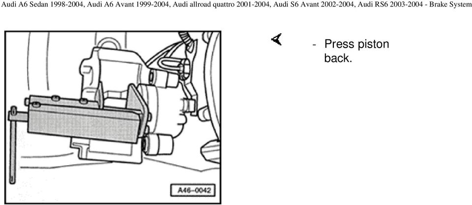
11 Remove both guide pins from brake caliper. - Remove brake caliper housing and support so that the weight of the brake caliper does not burden or damage the brake hose. - Remove brake pads from brake caliper housing or from brake carrier. Installing Note: Press piston back into caliper housing using resetting tool before inserting new brake pads. Before pushing back the piston, draw off brake fluid out of the brake fluid reservoir with a bleeder bottle. Otherwise, especially if reservoir has been topped off, fluid will overflow and cause damage.

12 - Press piston back.
13 Insert brake pad with retaining spring in brake caliper housing. Note: Inner pad (with spring) is marked with an arrow. The arrow must point in the direction of forward rotation of the brake disc when installed. Noise may result from incorrect installation. - Remove protective foil on backing plate of outer brake pad. - Install outer brake pad on brake carrier. - Install brake caliper housing in brake carrier using both guide pins (25 Nm). - Install both protective caps. - Install retaining spring in brake caliper housing. Note: After installing brake pads and before moving vehicle, depress brake pedal several times firmly to properly seat brake pads in their normal operating position.
. - Install both protective caps. - Install retaining spring in brake caliper housing.")
14 - Install wheels Tightening torque 120 Nm - Check brake fluid level and top off, if necessary.

15 j a t Front brakes FNR- G Front brakes, servicing Note: Always install the complete repair kit. After replacing brake pads and before moving vehicle, depress brake pedal several times firmly to properly seat brake pads in their normal operating position. Search Advanced Search Version: 2.5r01sp0003 When siphoning brake fluid, always use a bleeder bottle that is used exclusively for brake fluid. Brake fluid is poisonous. NEVER siphon brake fluid with your mouth!

16 46-11 The tightening torque of the brake lines is 15 Nm. Check that the brake caliper moves freely by moving it from side to side. 1 - Brake pads Note: The inner pad (with spring) has a cable for wear indicator. The outer brake pads are provided with an adhesive sheet on the backing plate of pad. Remove the protective sheet before inserting pads.

17 46-12 Different versions see Parts Catalog If worn, always replace on both sides of the car Removing and installing Page 46-7 Note: Always clean brake caliper thoroughly before installing new brake pads (must be free of grease). Be especially careful to remove any residual adhesive foil on the surface of the outer brake pads. 2 - Brake carrier Bolt to wheel bearing housing 3 - Ribbed bolt, 200 Nm Clean ribbing if reusing

18 M14 x 1.5 x 38

19 Bushing Insert into brake caliper housing 5 - Guide pin, 30 Nm 6 - Trim cap Remove Attach cable for wear indicator 7 - Brake disc If worn, always replace on both sides of the car Remove brake caliper prior to removing Lubricate contact surfaces between brake disc and wheel hub with polyurea grease G A2. Repair Manual, Brake System, Repair Group 00; Technical data

20 8 - Wheel bolts Tightening torque 120 Nm

21 Brake line connection to brake hose, 15 Nm 10 - Brake line Install in brake caliper housing Attach to brake hose, counter hold on brake hose hex when attaching Hose must be attached without twisting Make sure tabs are properly seated in retainer grooves 11 - Brake line connection to brake caliper, 17 Nm 12 - Bracket Bolt to brake caliper housing Attach brake line
22 Hex bolt M8 x 16 Tightening torque 25 Nm 14 - Brake caliper housing If repair work is necessary, do not hang by brake hose. Secure to vehicle using wire Aside from "Replacing brake pads" Page and "Front brake caliper, servicing" Page 46-24, no other repairs may be performed to the brake caliper Hose must be attached without twisting Repair Manual, Brake System, Repair Group 00; Technical data
23 Retaining spring Pay attention to correct installation position. Engage retaining spring on both studs of brake caliper housing and on the outer pad. Note: Retaining spring must be pressed under brake carrier after it is inserted in both holes. If the spring is improperly installed, the brake caliper cannot adjust to compensate for wear on the outer brake pad. This will cause the brake pedal travel to increase.
24 46-17 Brake pads, removing and installing Removing Note: Mark brake pads to be reused on removal. Reinstall in their original position to prevent uneven braking! Note direction of rotation -arrow on brake disc- and installation location -left or right- when installing brake discs. - Raise vehicle. - Remove wheels.
25 - Secure brake disc with a wheel bolt, see (arrow).
26 Using screwdriver, pry off brake pad retaining spring from brake caliper housing and remove. - Disconnect brake wear indicator connector - Using a screwdriver, release connector from holder turning connector by 90 at same time. - Detach connector out upward and unhook wire.
27 Detach brake line from bracket - Remove trim caps - 1-.
28 Unscrew both guide pins and remove from brake caliper. - Remove brake caliper housing and lay to one side so that the weight of the brake caliper does not stress or damage the brake hose. - Take brake pads out of brake caliper housing or from brake carrier. Use only methylated spirits to clean brake caliper housing.
29 46-21 Installing - Press back piston. Note: Press piston back into caliper housing using resetting tool before inserting new brake pads. Before pushing back the piston, draw off brake fluid out of the brake fluid reservoir with a bleeder bottle. Otherwise, especially if reservoir has been topped off, fluid will overflow and cause damage. WARNING! Brake fluid is poisonous and must not be siphoned by mouth through a hose.
30 - Insert brake pad with retaining spring and wear indicator into brake caliper housing.
31 Install outer brake pad -2- onto brake caliper. Note: Insert pads in brake carrier and install together on brake caliper and brake disc. - Secure brake carrier to brake caliper housing with both guide pins to 25 Nm. - Make sure brake hose is installed without twisting.
32 Install both protective caps. - Insert retaining spring into brake caliper housing. - Attach brake line - Plug in connector for wear indicator and engage line in dust cap and trim cap. - Install wheels Tightening torque 120 Nm Note:
33 Retaining spring must be pressed under brake carrier after it is inserted in both holes. If the spring is improperly installed, the brake caliper cannot adjust to compensate for wear on the outer brake pad. This will cause the brake pedal travel to increase. After installing brake pads and before moving vehicle, depress brake pedal several times firmly to properly seat brake pads in their normal operating position. - Check brake fluid level and top off, if necessary.
34 j a t Front brakes (HP-2) brake caliper/ aluminum Front brake caliper, servicing Note: Always install complete repair kit. After replacing brake pads and before moving vehicle, depress brake pedal several times firmly to properly seat brake pads in their normal operating position. Search Advanced Search Version: 2.5r01sp0003 When siphoning brake fluid, always use a bleeder bottle that is used exclusively for brake fluid. Brake fluid is poisonous. NEVER siphon brake fluid with your mouth! Brake line tightening torque: 15 Nm.
35 Brake disc Both sets of brake pads on front axle must always be replaced together Check for sufficient wear limit Remove brake caliper before removing Repair Manual, Brake System, Repair Group 00; Technical data 2 - Brake caliper If repair work is necessary, do not hang by brake hose. Secure to vehicle using wire
36 Aside from "Replacing brake pads" Page and "Front brake caliper, servicing" Page 47-16, no other repairs may be performed to brake caliper
37 Line retainer for wear indicator Insert line for brake pad wear indicator in line retainer 4 - Ribbed washer 5 - Ribbed bolt, 190 Nm Clean ribs if reusing 6 - Tensioning spring Slide to side Not removable 7 - Retaining spring
38
39 Harness connector Only on vehicles with wear indicator 9 - Brake hose Do not disconnect when removing brake pads 10 - Hex bolt, 25 Nm 11 - Bracket Bolt to brake caliper housing Insert harness connector for brake pad wear indicator
40
41 Brake line, 15 Nm 13 - Brake pads Both sets of brake pads on front axle must always be replaced together Different on left and right sides Removing and installing Page With wear indicator - Once wear limit is reached (limit: 3 mm), warning light in instrument cluster comes on. Remove adhesive foil from backing plates on outer brake pads before installing Repair Manual, Brake System, Repair Group 00;
42 Technical data
43 46-29 Brake pads, removing and installing Removing Note: If re-using brake pads, mark them so that they can be installed in their original positions to prevent uneven braking. - Raise vehicle. - Remove wheels.
44 - Secure brake disc using a wheel bolt.
45 Disconnect connector for brake pad wear indicator. - Disengage connector from bracket using a screwdriver and simultaneously turn connector Lift connector up and out and disengage wire. - Press upper and lower spring tensioner out of locking mechanism using pliers (arrows). - Slide spring to side.
46 46-31 Note: Before pushing back piston, siphon some of the brake fluid out of the brake fluid reservoir. Otherwise, especially if reservoir has been topped off, fluid will overflow and cause damage. WARNING! Brake fluid is poisonous. NEVER siphon brake fluid with your mouth. - Press piston back into brake caliper housing. - To do this, insert floating frame using a screwdriver as shown and press powerfully outward.
47 First use screwdriver to press outer brake pads off brake caliper.
48 Press floating frame firmly in direction of (arrow) until stop. - Pry brake pads carefully out of piston and remove brake caliper housing. Note: Clean brake caliper housing thoroughly before installing new brake pads. Be especially careful to remove any residual adhesive foil on outer brake pads. Installing - Insert lower and upper brake pads in piston. Note: Make sure protrusions on backing plates are securely fitted in brake piston. Do not damage protective caps when installing brake pads.
49 Press floating frame outward until stop. - Remove protective foil on backing plates of outer brake pads. - Make sure protrusions on backing plate are securely fitted in floating frame. Note: After replacing brake pads and before moving vehicle, always depress brake pedal several times firmly to properly seat brake pads in their normal operating position.
50 Remove wheel bolt from wheel hub. Note: When installing wheels, make sure rim flange does not rest on brake caliper. This could push brake pads out of position. - Install wheels Tightening torque 120 Nm - Check brake fluid level and top off, if necessary.
51 just a test. Rear brakes C38 Brake calipers, servicing Rear brakes with automatic adjustment Note: Always install the complete repair kit. After replacing brake pads and before moving vehicle, depress brake pedal several times firmly to properly seat brake pads in their normal operating position. Search Advanced Search Version: 2.5r01sp0003 When siphoning brake fluid, always use a bleeder bottle that is used exclusively for brake fluid. Brake fluid is poisonous. NEVER siphon brake fluid with your mouth!
52 Brakes can be tested on all normal commercial test equipment, provided the two brake test rollers are not driven faster than 5.5 km/h.
53 Self-locking bolts, 35 Nm Always replace When loosening and tightening counter-hold on guide pin 2 - Brake pads Brake pad sets on both sides of axle must always be replaced together Removing and installing Page Checking thickness Repair Manual, Maintenance Repair Manual, Brake System, Repair Group 00; Technical data 3 - Ribbed bolt, 95 Nm
54 Brake carrier with guide pins and protective cap Supplied as preassembled replacement part with sufficient grease on guide pins If protective caps or guide pins are damaged, install repair kit. Use grease packet supplied to lubricate guide pins 5 - Ribbed bolt, 95 Nm
55 Brake disc Brake pad sets on both sides of axle must always be replaced together Remove brake caliper before removing Repair Manual, Brake System, Repair Group 00; Technical data 7 - Brake caliper housing Do not disconnect brake hose when changing brake pads Tighten brake hose to brake caliper housing to 45 Nm Hose must be installed twist-free Servicing brake caliper Page 46-24
56 46-52 Brake pads, removing and installing Special tools and equipment 3272 reset tool
57 3272/1 support plate
58 46-53 Removing Note: If re-using brake pads, mark them so that they can be installed in their original positions to prevent uneven braking. - Remove wheels. - Counter-hold guide pins and remove self-locking bolts from brake caliper housing. - Remove brake pads.
59 46-54 Installing Note: Before pushing back the piston, siphon some of the brake fluid out of the brake fluid reservoir. When siphoning brake fluid, always use a bleeder bottle that is used exclusively for brake fluid. Brake fluid is poisonous. NEVER siphon brake fluid with your mouth! - Screw piston inward as far as it will go by turning threaded spindle clockwise and knurled section counterclockwise.
60 Remove protective foil on brake pad backing plates. - Insert brake pads. - Secure brake caliper housing using new self-locking bolts. - Tighten bolts on brake caliper housing to 35 Nm. Note: Repair kit includes four self-locking hex-bolts which must always be installed.
61 After replacing brake pads and before moving vehicle, always depress brake pedal several times firmly to properly seat brake pads in their normal operating position. - When installing, tighten wheels to 120 Nm. - Check brake fluid level and top off, if necessary.
62 just a test. Rear brakes C Brake caliper, servicing Rear brakes with automatic adjustment Note: Always install the complete repair kit. After replacing brake pads and before moving vehicle, depress brake pedal several times firmly to properly seat brake pads in their normal operating position. Search Advanced Search Version: 2.5r01sp0003 When siphoning brake fluid, always use a bleeder bottle that is used exclusively for brake fluid. Brake fluid is poisonous. NEVER siphon brake fluid with your mouth!
63 Brakes can be tested on all normal commercial test equipment, provided the two brake test rollers are not driven faster than 5.5 km/h.
64 Hex bolt, selflocking, 35 Nm Always replace When loosening and tightening counter hold on guide pin 2 - Brake caliper housing Unbolt caliper housing when changing brake pads Hose must not be twisted when installed Do not disconnect brake hose when changing brake pads Servicing brake caliper Page 47-30
65 Brake pads If required, always renew both sides together Do not disconnect brake hose when changing brake pads Removing and installing Page Checking thickness: Maintenance Manual 4 - Pad retaining spring Always replace when changing pads 5 - Brake disc If required, always replace both sides together
66 Remove brake caliper prior to removing Lightly coat contact surfaces between brake disc and wheel hub with polycarbamide grease G A2 Check degree of wear (wear limit) Repair Manual, Brake System, Repair Group 00; Technical data
67 Hexagon socket head bolts M10 x 60 Always renew M10 x 1.25 x 50 Tightening torque:70 Nm plus an additonal 90 1 / 4 turn M10 x 1.0 x 20 Tightening torque: 95 Nm 7 - Brake carrier with guide pin and protective cap Supplied as replacement part assembled with sufficient quantities of grease on guide pins
68 If protective caps or guide pins are damaged, install repair kit. Use grease packet supplied to lubricate guide pins. 8 - Banjo bolt, 40 Nm
69 Brake line with banjo union 10 - Seals Hose must not be twisted when installed Unbolt from brake carrier when changing pads Do not disconnect brake hose when changing brake pads Servicing brake caliper Page 47-30
70 46-61 Brake pads, removing and installing Special tools and equipment 3272 Resetting and removing tool
71 V.A.G 1331 Torque wrench
72 46-62 Removing Note: If re-using brake pads, mark them so that they can be installed in their original positions to prevent uneven braking. - Lift vehicle. - Remove wheels. - Secure brake disc with one wheel bolt.
73 Remove bolts from brake caliper housing, counterholding on guide pins. Note: Detach brake cable in order to replace bottom caliper bolt. - Take off brake caliper housing, and lay aside so the weight of caliper does not strain or damage brake hose. - Remove brake pads. - Take out retaining springs. - Clean caliper housing (especially seating surface for pad). Note: Brake carrier must be removed in order to replace disc.
74 46-64 Use only methylated spirits for cleaning caliper housing. Note: Press piston back into caliper housing using resetting tool before inserting new brake pads. Before pushing back the piston, draw off brake fluid out of the brake fluid reservoir with a bleeder bottle. Otherwise, especially if reservoir has been topped off, fluid will overflow and cause damage. WARNING! Brake fluid is poisonous and must on no account be siphoned off by mouth through a hose.
75 46-65 Installing Use only methylated spirits for cleaning caliper housing. - Screw in piston by turning special tool clockwise.
76 Install pad retaining springs. - Install pads.
77 Ensure pads are located in pad retaining springs (arrows). Note: The repair kit includes four self-locking hex bolts which must be installed. - Secure caliper housing with new self-locking bolts. - Make sure brake hose is not twisted when installed. - Tightening torque for securing caliper housing: 35 Nm
78 46-68 Note: After replacing brake pads and before moving vehicle, always depress brake pedal several times firmly to properly seat brake pads in their normal operating position. - Install wheels Tightening torque 120 Nm - Check brake fluid level and top off if necessary.
79 just a test. Parking brake cables, removing and installing Front wheel drive vehicles Note: Parking brake cable adjusting components are located in the tunnel on the underside of vehicle. Removing Search Advanced Search - Remove heat shield Version: 2.5r01sp Remove retaining nuts (arrows) from heat shield -2- and slide heat shield forward.
80 Remove locking clip - D-. - Counter-hold hex -E- using 13 mm open end wrench and turn adjusting nut -C- in until stop. - Slide cable adjuster together. - Disconnect parking brake cables from brake calipers. Note: Be careful not to damage parking brake boot when removing and installing.
81 Remove retainers from parking brake cable on rear axle beam. - Disconnect heat shield from area of rear muffler and move to one side.
82 Open retainer and remove parking brake cable. - Use a screwdriver to pry parking brake cable from console. - Remove center console extension. Repair Manual, Body Interior, Repair Group 68
83 Using screwdriver, press parking brake cable in direction of parking brake lever and push ball out of retainer. - Remove parking brake cable. Installing - Remove any plastic components on compensator; they do not need to be re-installed. - Use number 2 screwdriver to prevent compensator from turning. - Install ball head in compensator via console. Parking brake cable must engage in console - Secure parking brake cables to rear axle beam and install in retainers on underbody. - Adjust parking brake Page Install center console extension.
84 Repair Manual, Body Interior, Repair Group 68
85 46-74 All wheel drive vehicles Note: Parking brake cable adjusting components are located in front of rear lower control arms. Removing - Remove locking component - D-. - Counter-hold hex -E- using 13 mm open end wrench and turn adjusting nut -C- in until stop. - Slide cable adjuster together.
86 Disconnect parking brake cables from brake calipers. Note: Be careful not to damage parking brake boot when removing and installing.
87 - Loosen bolt - A-. - Remove parking brake cables from retainer.
88 Press tabs -A- together and remove parking brake cable from control arm. - Remove heat shield.
89 Loosen nuts on both metal retainers until parking brake cables can be removed. - Use a screwdriver to pry parking brake cable from console. - Remove center console extension. Repair Manual, Body Interior, Repair Group 68
90 Using screwdriver, press parking brake cable in direction of parking brake lever and push ball out of retainer. - Remove parking brake cable. Installing - Remove any plastic components on compensator; they do not need to be re-installed. - Use number 2 screwdriver to prevent compensator from turning. - Install ball head in compensator via console. - Parking brake cable must engage in console. - Secure parking brake cables to rear axle beam and install in metal retainers in tunnel. - Adjust parking brake Page
91 - Install center console extension. Repair Manual, Body Interior, Repair Group 68
92 just a test. Parking brake lever, removing and installing Removing - Remove center console extension. Repair Manual, Body Interior, Repair Group 68 - Remove hex-nuts Search Advanced Search - Press parking brake cable inward using screwdriver and remove parking brake lever. Version: 2.5r01sp0003 Installing - Install parking brake cable in compensator.
93 - Tighten nuts -1- to 25 Nm. - Adjust parking brake Page Install center console extension. Repair Manual, Body Interior, Repair Group 68
94 46-80 Parking brake, adjusting Note: Because the rear brakes are automatically selfadjusting, readjusting the parking brake is usually not necessary. Adjustment is only necessary after replacing parking brake cables, brake calipers, brake pads and brake discs. Hydraulic brake system must be free of air and functioning properly. - Depress brake pedal firmly at least once. - Make sure parking brake lever in released position. - Remove rear air vent from center console. Repair Manual, Body Interior, Repair Group 68
95 - Remove any plastic components on compensator; they do not need to be re-installed. - Use screwdriver to prevent compensator from turning (center console not shown in illustration).
96 46-81 Note: In All Wheel Drive (AWD) vehicles, parking brake cable adjusting components are located in front of rear lower control arms. For vehicles with Front Wheel Drive (FWD), they are located in the tunnel on the underside of vehicle. - Remove locking component - D-. - Counter-hold hex -E- using 13 mm open end wrench and turn adjusting nut -C- in until stop. - Slide cable adjuster -Btogether. - Unscrew adjusting nut until slot for locking component is visible. - Install locking component.
97 - Pull both cable sleeve adjusters apart simultaneously until cables are tensioned. Lever must not lift off at brake caliper during this process. - Remove screwdriver from compensator and apply parking brake firmly 3 times.
98 46-82 Note: Colored O-ring -1- must not be visible following successful installation. This ensures that the parking brake cable adjustment mechanism is sufficiently protected against dirt and water spray. - Check parking brake tension and adjust fine adjustment -A- in or out, if necessary until lever lifts slightly from brake caliper. - Note dimension -A-. Gap should be visible, but not be wider than 1.5 mm.
Volkswagen Jetta, Golf, GTI 1999, 2000 Brake System 46 Brakes - Mechanical Components (Page GR-46)
") 46 Brakes - Mechanical Components (Page GR-46) Front brakes Brake pads, removing and installing Brake pads, removing and installing FN 3 brake caliper, servicing FS III brake caliper, servicing Rear wheel
46 Brakes - Mechanical Components (Page GR-46) Front brakes Brake pads, removing and installing Brake pads, removing and installing FN 3 brake caliper, servicing FS III brake caliper, servicing Rear wheel
Rear wheel brakes, servicing. Стр. 1 из 45. Note:
 Volkswagen Touareg - Rear wheel brakes, servicing Стр. 1 из 45 46-2 Rear wheel brakes, servicing Rear brakes, FN 44 brake caliper, servicing Note: After replacing brake pads, depress brake pedal firmly
Volkswagen Jetta, Golf, GTI 1999, 2000 Brake System 47 Brakes - Hydraulic Components (Page GR-47)
") 47 Brakes - Hydraulic Components (Page GR-47) FS III front brake calipers, servicing Front brake caliper piston, removing and installing FN 3 front brake calipers, servicing Front caliper piston, removing
47 Brakes - Hydraulic Components (Page GR-47) FS III front brake calipers, servicing Front brake caliper piston, removing and installing FN 3 front brake calipers, servicing Front caliper piston, removing
Front axle components, overview
 just a test. Front axle components, overview 40-1 General Information Load bearing components and parts of the suspension must not be welded or straightened. Vehicles without drive axle must not be moved,
2003 Volkswagen Passat GLX 4Motion
 2001-2003 BRAKES Disc MODEL IDENTIFICATION Several different brake versions are used by Volkswagen. To aid in identifying brake system installed on a particular model, see BRAKE SYSTEM IDENTIFICATION table.
Drive shaft, servicing
 Volkswagen Passat B6 - Drive shaft, servicing Стр. 1 из 41 40-7 Drive shaft, servicing Drive shafts, overview I - Assembly overview: Drive axle with CV joint VL100 40-7, Drive axle with CV joint VL100,
Volkswagen B3 Passat Manual Transmission 02A 34 Manual Transmission - Controls, Assembly (Page GR-34) 02A 5-speed. Gearshift cable/lever installing
 02A 5-speed. Gearshift cable/lever installing") 34 Manual Transmission - Controls, Assembly (Page GR-34) 02A 5-speed Gearshift cable/lever installing Gearshift housing repairing Gearshift lever repairing lever/relay lever, installing Gearshift mechanism
34 Manual Transmission - Controls, Assembly (Page GR-34) 02A 5-speed Gearshift cable/lever installing Gearshift housing repairing Gearshift lever repairing lever/relay lever, installing Gearshift mechanism
Unit: mm(in) Item Standard value Service limit Axle shaft run out - 0.2(0.008)
 Item Standard value Service limit Axle shaft run out - 0.2(0.008)") Rear Wheel/Brake/Suspension 13. Rear Wheel/Brake/Suspension Service Information 13-1 Troubleshooting 13-2 Rear Wheel 13-3 Rear Cushion 13-4 Rear Swing Arm 13-7 Service Information General Safety If the
Rear Wheel/Brake/Suspension 13. Rear Wheel/Brake/Suspension Service Information 13-1 Troubleshooting 13-2 Rear Wheel 13-3 Rear Cushion 13-4 Rear Swing Arm 13-7 Service Information General Safety If the
Cooling system components, removing and installing
 Engine BHW Cooling system components, removing and installing Page 1 / 24 19-1 Cooling system components, removing and installing Warning! When doing any repair work, especially in the engine compartment,
2008 ACCORD - Front Knuckle/Hub/Wheel Bearing Replacement (page 18-13)
") 2008 ACCORD - Front Knuckle/Hub/Wheel Bearing Replacement (page 18-13) Exploded View Special Tools Required Ball joint remover, 28 mm 07MAC-SL0A202 Hub dis/assembly tool 07GAF-SD40100 Bearing driver attachment,
2008 ACCORD - Front Knuckle/Hub/Wheel Bearing Replacement (page 18-13) Exploded View Special Tools Required Ball joint remover, 28 mm 07MAC-SL0A202 Hub dis/assembly tool 07GAF-SD40100 Bearing driver attachment,
STEERING HANDLEBAR/FRONT WHEEL/ FRONT SHOCK ABSORBER
 14 14 STEERING HANDLEBAR/FRONT WHEEL/ SCHEMATIC DRAWING ------------------------------------------------- 14-1 SERVICE INFORMATION------------------------------------------------ 14-2 TROUBLESHOOTING-----------------------------------------------------
2005-2007 Ford Focus Front Brake Rotors
 2005-2007 Ford Focus Front Brake Rotors Replacement Replacing the rotors in 2005-2007 Ford Focus models with rear drum brakes. Written By: David Hodson INTRODUCTION The steps in this guide are used to
Rebuild Instructions for 70001 and 70010 Transmission
 Rebuild Instructions for 70001 and 70010 Transmission Brinn, Incorporated 1615 Tech Drive Bay City, MI 48706 Telephone 989.686.8920 Fax 989.686.6520 www.brinninc.com Notice Read all instructions before
2007 Hummer H3. 2007 BRAKES Disc Brakes - H3. Fastener Tightening Specifications Specification Application
 2007 BRAKES Disc Brakes - H3 SPECIFICATIONS FASTENER TIGHTENING SPECIFICATIONS Fastener Tightening Specifications Specification Application Metric English Backing Plate Bolts 135 N.m 100 lb ft Brake Hose
Installation instruction do88 Intercooler for Volvo S40 / V50 / C30
 Installation instruction do88 Intercooler for Volvo S40 / V50 / C30 This instruction shows how to replace the OEM intercooler with our performance intercooler. 2. 3. 1. 4. 5. Part number: ICM-170 6. At
1993 SUSPENSION Volkswagen Front. EuroVan
 Article Text ARTICLE BEGINNING 1993 SUSPENSION Volkswagen Front EuroVan DESCRIPTION FWD independent suspension is an double-wishbone type with torsion bars mounted on upper control arm. Wheel is supported
GTI VR6 Front Wheel Bearing DIY http://www.gtishrine.com
 GTI VR6 Front Wheel Bearing DIY http://www.gtishrine.com This procedure covers replacing the front wheel bearings. Tools and Parts required: Wheel Bearing Puller w/ ABS adapter. Available for rent from
DO NOT attempt to repair hub and wheel bearing assembly.
 Page 1 of 6 HUB & WHEEL BEARINGS (WITH PULSE VACUUM HUBLOCK) DO NOT attempt to repair hub and wheel bearing assembly. Removal DO NOT remove hub lock assembly by prying on hub lock legs. This can crack
S&G Model 2937 Group 1 Combination Lock
 Installation and Combination Changing Instructions S&G Model 2937 Group 1 Combination Lock NOTE: READ COMPLETE INSTRUCTIONS BEFORE INSTALLATION These instructions should be followed when installing the
2005 MINI Cooper. 2002-05 MANUAL TRANSMISSIONS On-Vehicle Servicing. Cooper S Getrag 285
 2002-05 MANUAL TRANSMISSIONS On-Vehicle Servicing APPLICATION MANUAL TRANSMISSION APPLICATIONS Application Transmission Model Cooper R65 Cooper S Getrag 285 LUBRICATION SERVICE INTERVALS Inspect fluid
SERVICE PARTS LIST PAGE 1 OF 6 BASE ASSEMBLY SPECIFY CATALOG NO. AND SERIAL NO. WHEN ORDERING PARTS 12" DUAL BEVEL COMPOUND MITER SAW B27A
 PAGE 1 OF 6 BASE ASSEMBLY 00 0 EXAMPLE: Component Parts (Small #) Are Included When Ordering The Assembly (Large #). SPECIFY CATALOG NO. AND NO. WHEN ORDERING PARTS 1 02-80-0050 Thrust Bearing (1) 2 05-80-0510
Volkswagen Phaeton 44-2 Wheel and tire mounting Wheel mounting Mounting tires Pressing off tires Dismounting tires Mounting tires
 Wheel and tire mounting Стр. 1 из 1 Volkswagen Phaeton 44-2 Wheel and tire mounting Wheel mounting Wheel bolt to hub Torque specification: 120 Nm Mounting tires The tires are installed as usual, but note
Char-Lynn Hydraulic Motor. Repair Information. 10 000 Series. October, 1997
 Char-Lynn Hydraulic Motor October, 1997 Repair Information Geroler Motor Two Speed 001 27 Retainer inside bore of valve plate bearingless motors only 4 15 16 3 6 35 Parts Drawing 25 2 2 1 19 17 36 40 47
DiscPlus DX195 and DX225 Air Disc Brakes
 Revised 11-04 Technical Bulletin Revised 1 Technical 11-04 Bulletin DiscPlus DX195 and DX225 Air Disc Brakes Inspection, Installation and Diagnostics Air Disc Brake Inspection Intervals and Procedures
FRONT BUMPER INSTALLATION INSTRUCTIONS 2007-2011 DODGE / MERCEDES SPRINTER
 Aluminess Products Inc 9402 Wheatlands Ct. #A Santee, CA 92071 619-449-9930 FRONT BUMPER INSTALLATION INSTRUCTIONS 2007-2011 DODGE / MERCEDES SPRINTER Please read before beginning Stainless steel hardware
13. REAR WHEEL/BRAKE/SUSPENSION
 13. REAR WHEEL/BRAKE/SUSPENSION 13 3.5~4.5kg-m 8.0~10.0kg-m 0.8~1.2kg-m 3.0~4.0kg-m 2.4~3.0kg-m 3.5~4.5kg-m 6.0~8.0kg-m 13-0 13. REAR WHEEL/BRAKE/SUSPENSION 13 REAR WHEEL/BRAKE/SUSPENSION SERVICE INFORMATION...
Owner s Manual Read and keep this manual. Patents World Wide
 Owner s Manual Read and keep this manual. Patents World Wide S & S Industries, Inc., Sarasota, FL, USA www.trail-gator.com Copyright 2008 All Rights Reserved The following manual is provided to assist
Engine, disassembling and assembling
 13-1 Engine, disassembling and assembling Note: Replace the oil cooler and thoroughly clean the oil passages if you find metal shavings or larger quantities of small metal particles in the engine oil,
DYNA RIDER FOOTBOARD KIT
 -J0 REV. 0-0-0 DYNA RIDER FOOTBOARD KIT GENERAL Kit Number 000 Models For model fitment information, see the P&A Retail Catalog or the Parts and Accessories section of www.harley-davidson.com (English
FOR ANY QUESTIONS, PLEASE CALL US @ 727.347.9915 M-F 8:00a.m.-8:00p.m. EST. REAR BRAKES 1 AEROSPACE COMPONENTS 727.347.9915
 REAR BRAKES 1 AEROSPACE COMPONENTS 727.347.9915 REAR BRAKES Before getting started, remove all stock braking components. Pre-assembly of parts: Clean the bolts and the threads in the hat with acetone.
AXLE SHAFTS - FRONT. 1998 Pontiac Bonneville MODEL IDENTIFICATION DESCRIPTION & OPERATION TROUBLE SHOOTING REMOVAL & INSTALLATION
 AXLE SHAFTS - FRONT 1998 Pontiac Bonneville 1998-99 DRIVE AXLES FWD Axle Shafts - Cars - "C", "G" & "H" Bodies GM Aurora, Bonneville, Eighty Eight, LeSabre, LSS, Park Avenue, Regency, Riviera MODEL IDENTIFICATION
Steering column, steering column tube and steering wheel, servicing
 48-1 Steering column, steering column tube and steering wheel, servicing Airbag functional check and airbag On Board Diagnostic (OBD) program Repair Manual, Body-Exterior, Body- Interior, Repair Group
How Do I Replacing My Rear Brake Pads and Rotors?
 How Do I Replacing My Rear Brake Pads and Rotors? WARNING! Always have the vehicle under inspection on level ground, in park with the emergency brake on. Always wear protective eyewear, gloves and necessary
CorkSport Mazdaspeed 6 Rear Sway Bar 2006-2007 Mazdaspeed 6
 CorkSport Mazdaspeed 6 Rear Sway Bar 2006-2007 Mazdaspeed 6 Pre-Installation Notes: The CorkSport Rear Sway Bar is a great addition to improving the handling performance to the Mazdaspeed 6. It will minimize
MKV Golf GTI Rear Brake Service - Replace Pads and Rotors
 Page 1 Installation Procedures MKV Golf GTI Rear Brake Service - This tutorial is provided as a courtesy by ECS Tuning. Proper service and repair procedures are vital to the safe, reliable operation of
Webinar Series. Committee. Disc Brake Wheels Off Inspection and Reline. Presents
 1 APTA Bus Webinar Technical Series Maintenance Committee Webinar Series Presents Disc Brake Wheels Off Inspection and Reline January 21, 2015 2 Introduction Welcome to today s webinar in which we will
Model No: VS4815 1. SAFETY INSTRUCTIONS VS4800 2. INTRODUCTION & APPLICATIONS VS4815 3. CONTENTS. 2.1 Introduction. 2.
 Instructions for: Petrol Engine Twin Camshaft Setting / Locking Tool Kit - (incorporating Vanos Alignment) - BMW N42 & N46 Engines Model No: VS4800 Associated kit: Camshaft/Carrier Bracket Remover & Installer
Eliminator Vented Disc Brake Owners Manual
 Eliminator Vented Disc Brake Owners Manual Eliminator Vented Disc Brakes Exclusive Features Whenever possible, the tendency is to use an aluminum alloy in order to reduce weight. These alloys are much
Volkswagen New Beetle 2.0 Liter 4-cyl General, Engine (Engine Code AEG) 15 Engine- Cylinder head, Valvetrain (Page GR-15)
 15 Engine- Cylinder head, Valvetrain (Page GR-15)") 15 Engine- Cylinder head, Valvetrain (Page GR-15) Cylinder head, removing and installing Compression, checking Valve train, servicing Camshaft oil seal, replacing Camshaft, removing and installing Hydraulic
15 Engine- Cylinder head, Valvetrain (Page GR-15) Cylinder head, removing and installing Compression, checking Valve train, servicing Camshaft oil seal, replacing Camshaft, removing and installing Hydraulic
CHROME FRONT BRAKE MASTER CYLINDER KIT
 -J075 REV. 009-0-0 CHROME FRONT BRAKE MASTER CYLINDER KIT GENERAL Kit Number 5-99D, 5-99D Models These Chrome Master Cylinder Kits are designed to replace the original equipment front brake master cylinder
DANA 30 MANUAL HUB CONVERSION KIT
 DANA 30 MANUAL HUB CONVERSION KIT 12194 PLEASE READ AND UNDERSTAND ALL INSTRUCTIONS BEFORE YOU BEGIN Your safety and the safety of other motorists is very important. Your Jeep is an off road capable vehicle
Cooling system components, removing and installing
 Page 1 of 34 19-1 Cooling system components, removing and installing WARNING! The cooling system is pressurized when the engine is warm. When opening the expansion tank, wear gloves and other appropriate
Pallet Jack. OWNER S MANUAL Model MH1230. Important Safety Instructions Assembly Instructions Parts and Hardware Identification
 OWNER S MANUAL Model MH1230 Important Safety Instructions Assembly Instructions Parts and Hardware Identification Pallet Jack CAUTION: Read, understand and follow ALL instructions before using this product
- power windows - alarm system - electric door mirror control - door warning light - central locking - seat memory
 Door Wiring Harness Plug Connections Binder -, Electrics Vehicle Type: (86) Model Year: 7 (V) Concern: Door wiring harness plug connections X11 / X12. Information: The rubber boot for the door connector
2003 Audi A4. AUDI' '3.0L V6 - AVK Engine - A4 & A6
 Installation (A4) CAUTION: Before installation, ensure camshafts are aligned, crankshaft is locked in place and camshaft gear bolts are loose as described in removal procedures. When turning camshaft,
INSTALL/REMOVAL INSTRUCTIONS: WINDOW REGULATOR
 REMOVAL/INSTALL OF WINDOW REGULATOR (741-306) Honda Accord 2003 07 General Tech Tips: Use painter s tape rather than duct tape to secure window. It will not damage paint or leave sticky residue. A plastic
Rollator Cane and Brake Replacement SAFETY SUMMARY (CONTINUED)
") Rollator Cane and Replacement Assembly, Installation and Operating Instructions SAVE THESE INSTRUCTIONS NOTE: Check ALL parts for shipping damage. If shipping damage is noted, DO NOT use. Contact Carrier/Dealer
Rollator Cane and Replacement Assembly, Installation and Operating Instructions SAVE THESE INSTRUCTIONS NOTE: Check ALL parts for shipping damage. If shipping damage is noted, DO NOT use. Contact Carrier/Dealer
BILLET HEADLAMP SHELL
 -J008 REV. 007-07- BILLET HEADLAMP SHELL GENERAL Kit Number 770-0 Models For model fitment information, please see the P&A Retail Catalog or the Parts and Accessories section of www.harleydavidson.com
Drum Brake Owners Manual
 Drum Brake Owners Manual TIE DOWN ENGINEERING, Inc. 5901 Wheaton Drive, Atlanta, GA 30336 www.tiedown.com (404) 344-0000 Fax (404) 349-0401 2007 TIE DOWN ENGINEERING, INC. ALL RIGHTS RESERVED Instruction
Rating when used as a weight carrying hitch without spring bars:
 BOLT-TOGETHER WEIGHT DISTRIBUTING HITCH SYSTEM Rating when used as a weight distributing hitch with spring bars: Part Number 48051 4805 48053 48054 Max Tongue Weight 550 Ibs. 750 Ibs. 1000 Ibs. 1400 lbs.
Class 5 to 7 Truck and Bus Hydraulic Brake System
 Class 5 to 7 Truck and Bus Hydraulic Brake System Diagnostic Guide 1st Edition * 5+0 Important Service tes The information in this publication was current at the time of printing. The information presented
STEERING SYSTEM - POWER
 STEERING SYSTEM - POWER 1990 Nissan 240SX 1990 STEERING Nissan - Power Rack & Pinion Axxess, Maxima, Pulsar NX, Sentra, Stanza, 240SX, 300ZX DESCRIPTION The power steering system consists of a rack and
Hydraulic Disc Brake, Installation, Maintenance, and Service Manual
 Hydraulic Disc Brake, Installation, Maintenance, and Service Manual HFX-Mag HFX-9 45-14550DWeb 02/06 copyright 2006 Hayes Bicycle Group, LLC Introduction to this Manual This manual is intended to provide
MEASURING WHEEL ALIGNMENT
 MEASURING WHEEL ALIGNMENT 2003-04 WHEEL ALIGNMENT Specifications & Procedures - Hummer - H2 Steering and vibration complaints are not always the result of improper alignment. One possible cause is wheel
8) Push piston in the remaining distance while bleeding through bleed nipple
 Push piston in the remaining distance while bleeding through bleed nipple") 1 of 16 Replacing Brake pads on a Jeep Cherokee (XJ) Copyright 2004 jeep@blackonyx.net *All things shown or advice given in this PDF is to give you ideas of what can be done. They may not be suited to
1 of 16 Replacing Brake pads on a Jeep Cherokee (XJ) Copyright 2004 jeep@blackonyx.net *All things shown or advice given in this PDF is to give you ideas of what can be done. They may not be suited to
Service Manual Rol-Lift
 R 2000 Service Manual Rol-Lift Series: T and E Developed by Generic Parts Service This manual is intended for basic service and maintenance of the Rol-Lift pallet jack. The pallet jacks you are servicing
Round Housing with Side Ports
 Power Steering Steering Control Unit (SCU) Parts and Repair Information 5 Series Steering Control Units 001 Square Housing with Side Ports Round Housing with Side Ports T E L RP Round Housing with End
1.8 CRANKSHAFT OIL SEALS
 SERIES 60 SERVICE MANUAL 1.8 CRANKSHAFT OIL SEALS An oil seal is fitted between each end of the crankshaft and the bores of the flywheel housing and gear case cover to retain the lubricating oil in the
Operating Instructions Parts List Manual Scissor Lift Pallet Truck
 Operating Instructions Parts List Manual Scissor Lift Pallet Truck Note: Operator MUST read and understand this operating instructions before use this Hand Scissor Lift. Thank you for using this hand scissors
Checking Wheel Brakes Wear
 Issue 1 en 1 Checking Wheel Brakes Wear Contents Disc Brakes... 3 Removing the wheels... 4 Checking the Brake Pads... 5 Check brake disc thickness... 7 Checking brake disc for cracks... 8 Drum Brakes...
Operation of the overrun braking system.
 Operation of the overrun braking system. Fig 1 The overrun device can be described as the control device of the overrun brake system. A draw-bar force is produced at the coupling point by reducing the
Solstice/Sky Water Pump Replacement
 Solstice/Sky Water Pump Replacement The water pump on the Solstice/Sky is starting to need replacement on some vehicles. This guide will help in replacing the water pump while the engine is still in the
White Industries Rear Hub Instructions
 White Industries Rear Hub Instructions Tool required: 2mm allen/hex wrench, 19mm socket, 20mm socket, and mallet. 1. Loosen the set screws located in the adjusting collar by using a 2mm allen wrench inserted
INSTALL/REMOVAL INSTRUCTIONS: WINDOW LIFT MOTOR
 REMOVAL/INSTALL OF WINDOW LIFT MOTOR (742-273) Ford Expedition 1997 2002, Lincoln Navigator 1998 2002, Ford F-150 Super Crew Cab 2001 General Tech Tips: Use painter s tape rather than duct tape to secure
INSTALLATION INSTRUCTIONS
 INSTALLATION INSTRUCTIONS Accessory Application Publications No. AII23628 2003 PILOT Issue Date MAY 2002 PARTS LIST Security System Kit (sold separately): P/N 08E51-S84-100 2 Remote controls Attachment
DR90. Baja Motorsports Inc. P.O. Box 61150 Phoenix, AZ 85082 Toll Free: 888-863-2252 PART NUMBERS AND PRICES ARE SUBJECT TO CHANGE 1 of 51
 DR90 Toll Free: 888-863-2252 PART NUMBERS AND PRICES ARE SUBJECT TO CHANGE 1 of 51 CYLINDER & CYLINDER HEAD 1 DR90-001 842645048166 CYLINDER 1 1 2 DR90-002 842645048173 GASKET, CYLINDER 1 1 3 DR90-003
Recall R136 Front Lower Ball Joints Check Torque or Replace
 SERVICE DATE /00 Amended /00 TECHNICAL BULLETIN Recall R6 Front Lower Ball Joints Check Torque or Replace MODEL VIN Remove and destroy Bulletin S04-R6, dated /00. Replace with this Bulletin. Revisions
TUTORIAL. REbUILdING. front CALIpER O-RING CONVERSION CORVETTE 1965-82. Part #: HT-1
 Part #: HT-1 1965-82 CORVETTE O-RING CONVERSION front CALIpER REbUILdING TUTORIAL Choosing a Brake Caliper Rebuild Kit Standard Lip Seals vs. O-Ring Seals Lip seal design seals are used on 1965-1982 Corvette
6 inch A-Arm Lift Kit WARNING: 16-018/16-019. installation instructions. will fit CLUB CAR DS. included:
 Revised May 205 6-08/6-09 6 inch A-Arm Lift Kit will fit CLUB CAR DS installation instructions included: Rear Lift Blocks Main Suspension Assembly Spindles A-Arms Rear Shock Mounting Plates U-Bolts WARNING:
SCION tc 2005-2008 COIL OVER SUSPENSION Preparation
 SCION tc 2005-2008 COIL OVER SUSPENSION Preparation Part Number: PTR11-21070 NOTE: Part number of this accessory may not be the same as the part number shown. Kit Contents: Item # Quantity Reqd. Description
Tool And Material Checklist
 HOW - TO CV JOINTS CV JOINTS Tool And Material Checklist Screwdriver Metal Shears Breaker Bar or Torque Wrench Assorted Wrenches Wire Evaporating Spray Solvent Pusher Tool Vise Snap Ring or Duckbill Pliers
AXLE SHAFTS - FRONT. 1993 Toyota Celica DESCRIPTION REMOVAL, DISASSEMBLY, REASSEMBLY & INSTALLATION. 1993 DRIVE AXLES Toyota FWD Axle Shafts
 AXLE SHAFTS - FRONT 1993 Toyota Celica 1993 DRIVE AXLES Toyota FWD Axle Shafts Toyota; Celica DESCRIPTION Axle shafts transfer power from transaxle to driving wheels. All axle shafts consist of a shaft
Installation instructions, accessories. Cruise control. Volvo Car Corporation Gothenburg, Sweden. Instruction No Version Part. No. 30739998 1.
 Instruction No Version Part. No. 30739998 1.1 Cruise control Page 1 / 11 Equipment A0000162 A0000161 A0801178 D8802049 Page 2 / 11 M8802108 Page 3 / 11 IMG-223164 Page 4 / 11 IMG-213320 Page 5 / 11 INTRODUCTION
Installation Instructions and Service Manual
 Installation Instructions and Service Manual Model 85, 85-3/4 & 85E Actuator* for Trailer Brakes 8,500 lbs. Capacity for use with -5/16 Hitch Balls Drum Brake Ready - Part #4736 Disc Brake Ready - Part
CONGRATULATIONS! TABLE OF CONTENTS. 1 Safety Warnings 2 About Your Wheels 3 Setting Up Your Wheels 7 Care and Cleaning 8 Warranty
 WHEEL MANUAL CONGRATULATIONS! Congratulations on your purchase of Oval Concepts Wheels. Developed to perform at a high level, it is important that you follow the operation and maintenance instructions
Installation Instructions 4508 4508S
 SYMPHONY Spread Lavatory Faucet with Speed Connect Drain Congratulations on purchasing your American Standard faucet with Speed Connect drain, a feature found only on American Standard faucets. Speed Connect
Cylinder head, removing and replacing
 15-1 Cylinder head, removing and replacing WARNING! Do not re-use any fasteners that are worn or deformed in normal use. Some fasteners are designed to be used only once, and are unreliable and may fail
Range Road RR Series Semi-Automatic Firewood Processor. Crated Unit Assembly Manual
 Range Road RR Series Semi-Automatic Firewood Processor Crated Unit Assembly Manual 1 1) Undo 8-18mm x 19mm Nuts and bolts, 2 on each leg of top frame 2) Lift top of Metal crate off and move out of work
5800 Temperature Sensor Cable Assembly
 5800 Temperature Sensor Cable Assembly Removal and Replacement Instruction Sheet #60-4702-070 Revision D, January 14, 2013 Overview The 5800 has two refrigeration temperature sensors, one attached to the
Trillium 40 Axis Spring Tensioner Wire Replacement Instructions
 Trillium 40 Axis Spring Tensioner Wire Replacement Instructions 1 Overview The objective is to replace the broken axis spring tensioner wire. This requires the following tasks: 1. Remove the seismometer
This is the civilian transfer case with the cooling loop only found in the driven gear half of the front case.
 INTRODUCTION The Transfer case used in the AMG Hummer is a New Venture Gear, model 242. This case has been in use for the H-1/Hummer since the early 1990 s. There have been modifications to the internal
DR50 Hensim Dirt Runner 49cc Dirt Bike (VIN PREFIX LLCH or LUAH)
") Page 1 of 21 Product Information Baja Web > Product Information > Parts Lists > DIRTBIKE > DR50 Hensim Dirt Runner 49cc Dirt Bike (VIN PREFIX LLCH or LUAH) DR50 Hensim Dirt Runner 49cc Dirt Bike (VIN PREFIX
Page 1 of 21 Product Information Baja Web > Product Information > Parts Lists > DIRTBIKE > DR50 Hensim Dirt Runner 49cc Dirt Bike (VIN PREFIX LLCH or LUAH) DR50 Hensim Dirt Runner 49cc Dirt Bike (VIN PREFIX
Micro Cart User's Guide
 Micro Cart User's Guide To take full advantage of the ergonomic features of your new Sun Mountain Micro Cart, please read the following information. SUN MOUNTAIN 1 Your Micro Cart has several innovative
STORAGE, INSTALLATION AND MAINTENANCE PROCEDURES
 GATE VALVE O.S. & Y 1.0 Periodic Inspections 1.1 The valve stem packing should be inspected at least monthly. If the stem packing shows signs of leakage, simply tighten the adjusting nuts to compress the
Stainless Steel Single and Dual Circulation Kits
 Instruction Sheet P/N 160780 01 Stainless Steel Single and Dual Circulation Kits Introduction The single and dual high-pressure circulation kits allow you to vary and control the circulation rate of coating
LIFT-505. BMF Lift Kit. Yamaha Drive Gas or Electric. Installation Instructions
 LIFT-505 BMF Lift Kit Yamaha Drive Gas or Electric Installation Instructions Contents of LIFT-505 Yamaha Drive BMF Lift Kit: a (1 ea.) BMF A-Arm Assembly b (1 ea.) Driver Side Shock Tower c (1 ea.) Passenger
AUTO TRANS DIAGNOSIS Article Text 1998 Volkswagen Passat This file passed thru Volkswagen Technical Site - http://volkswagen.msk.
 AUTO TRANS DIAGNOSIS Article Text 1998 Volkswagen Passat This file passed thru Volkswagen Technical Site - http://volkswagen.msk.ru ARTICLE BEGINNING 1997-98 AUTOMATIC TRANSMISSIONS Volkswagen Shift Interlock
Figure 2 The fan and shroud also needs to be removed for access to the four a/c compressor bolts and removal of the compressor from the top.
 Here are some pictures to show what s required when replacing the A/C compressor, expansion valve and receiver/drier on a 2001 Volvo V70. Even if you don t replace these A/C parts these pictures can help
INTRODUCTION KINGPIN REPLACEMENT
 KINGPIN REPLACEMENT Author: Randy Baumann All information, illustrations and specifications are based on the best information available at the time of publication. The author cannot guarantee the accuracy
2011-14 F250 6 RADIUS ARM KIT
 92154000 Thank you for choosing Rough Country for your suspension needs. 2011-14 F250 6 RADIUS ARM KIT Rough Country recommends a certified technician installs this system. In addition to these instructions,
1/29/2008 DR70. Baja Motorsports Inc. P.O. Box 61150 Phoenix, AZ 85082 Toll Free: 888-863-2252 PART NUMBERS PRICES ARE SUBJECT TO CHANGE 1 of 43
 DR70 Toll Free: 888-863-2252 PART NUMBERS PRICES ARE SUBJECT TO CHANGE 1 of 43 CYLINDER & CYLINDER HEAD 1 DR70-001 883099044472 CYLINDER 1 1 2 DR70-002 883099044489 GASKET, CYLINDER 1 1 3 DR70-003 883099044496
Fitting Instructions Garador, Westland & Catnic Garage Door Spring Box Roller Wheels & Wall Bracket & Link Arm
 Fitting Instructions for a Garador, Westland & Catnic Garage Door Spring Box Roller Wheels & Wall Bracket & Link Arm These instructions cover, how to replace a Spring Box Assembly to a Garador, Westland
Verify caster, camber and toe-in are correct before proceeding.
 If rotating the tie rod end 360 degrees changes the toe-in too much, use the rack tie rod to make smaller adjustments. Put the tie rod end in the steering arm and snug the castle nut before adjusting.
758 Heavy-duty Ratchet Guy Wire Cutter
 INSTRUCTION MANUAL 758 Heavy-duty Ratchet Guy Wire Cutter Read and understand all of the instructions and safety information in this manual before operating or servicing this tool. Register this product
INSTALLATION INSTRUCTIONS. 6111 Air Spring Kit 2011+ Ford F250/F-350 Single Wheel 2WD 2011+ Ford F350 Dually 2WD IMPORTANT NOTES
 INSTALLATION INSTRUCTIONS 6111 Air Spring Kit 2011+ Ford F250/F-350 Single Wheel 2WD 2011+ Ford F350 Dually 2WD Thank you for purchasing a quality Hellwig Product. PLEASE READ THIS INSTRUCTION SHEET COMPLETELY
Overview PARTS LIST. B. Lever mounting base C. Flush handle assembly D. Grey/Blue float stop E. Grey float (Full Flush) F. Flush valve washer
 F. Flush valve washer") Overview READ ENTIRE INSTRUCTIONS BEFORE STARTING INSTALLATION PARTS LIST A. Flush valve B. Lever mounting base C. Flush handle assembly D. Grey/Blue float stop E. Grey float (Full Flush) F. Flush valve
Overview READ ENTIRE INSTRUCTIONS BEFORE STARTING INSTALLATION PARTS LIST A. Flush valve B. Lever mounting base C. Flush handle assembly D. Grey/Blue float stop E. Grey float (Full Flush) F. Flush valve
EZ-Steer Assisted Steering System
 EZ-Steer Assisted Steering System Installation Instructions Platform Kit P/N 53059-21 Case IH Puma 165 Puma 180 Puma 195 Puma 210 New Holland T7030 T7040 T7050 T7060 Revision A June 2007 Part Number 53345-21-EU2
FL ADJUSTABLE RIDER BACKREST MOUNTING HARDWARE KIT
 -J070 REV. 0-0-0 FL ADJUSTABLE RIDER BACKREST MOUNTING HARDWARE KIT GENERAL Kit Number 9-09A Models For model fitment information, see the P&A Retail Catalog or the Parts and Accessories section of www.harley-davidson.com
TUTORIAL. REbUILdING. REAR CALIpER O-RING CONVERSION CORVETTE 1965-82. Part #: HT-2
 Part #: HT-2 1965-82 CORVETTE O-RING CONVERSION REAR CALIpER REbUILdING TUTORIAL Choosing a Brake Caliper Rebuild Kit Standard Lip Seals vs. O-Ring Seals Lip seal design seals are used on 1965-1982 Corvette
Windshield Wiper System
 Volkswagen Golf 5 - Windshield Wiper System Volkswagen Technical Site: http://volkswagen.msk.ru http://vwts.info Page 1 / 15 92-1 Windshield Wiper System General information The windshield wiper system