12. REAR WHEEL/BRAKE/SUSPENSION
|
|
|
- Grace Franklin
- 7 years ago
- Views:
Transcription
1
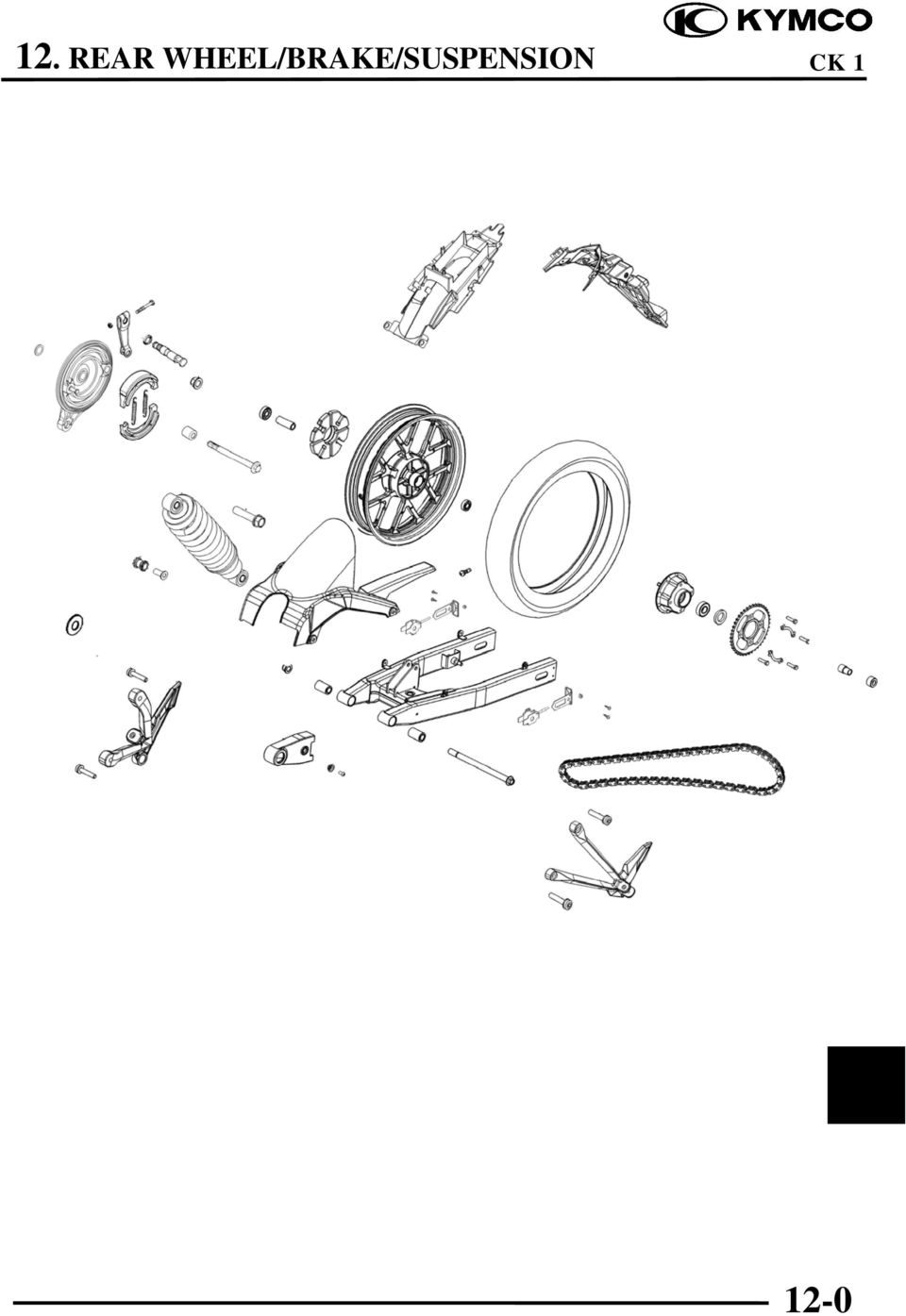
2 SERVICE INFORMATION REAR BRAKE TROUBLESHOOTING REAR SHOCK ABSORBER REAR WHEEL REAR FORK SERVICE INFORMATION GENERAL INSTRUCTIONS When installing the drive chain joint clip, the cutout of the clip should be opposite to the rotating direction. After the drive chain is adjusted, make sure that the rear brake pedal free play is normal and adjust it if necessary. SPECIFICATIONS Item Standard (mm) Service Limit (mm) Rear axle shaft runout 0.2 Rear rim runout Axial 2.0 Radial 2.0 Rear brake drum I.D Rear brake lining thickness Rear shock absorber spring free length TORQUE VALUES Rear shock absorber upper mount nut 3.0~4.0kg-m Rear shock absorber lower mount nut 3.0~4.0kg-m Rear axle nut 6.0~8.0kg-m Rear fork pivot nut 5.5~6.5kg-m Rear shock absorber damper nut 1.9~2.8kg-m SPECIAL TOOLS Crshion assemble & Disassemble F

3 TROUBLESHOOTING Rear wheel wobbling Bent rim Worn rear wheel bearing Loose or broken wheel spoke wires Faulty tire Improperly tightened axle nut Loose rear fork pivot nut Soft suspension Weak shock absorber spring Improperly adjusted shock absorber Damper oil leaks Poor brake performance Improperly adjusted brake Worn brake linings Contaminated or damaged brake linings Worn brake cam Worn brake drum Improperly installed brake linings Worn brake shoes at cam contacting area Worn camshaft Hard suspension Improperly adjusted shock absorber Rear suspension noise Bent rear shock absorber Loose shock absorber fasteners Insufficient damper oil 12-2

4 REAR WHEEL REMOVAL Remove the four bolts attaching the drive chain covers and then remove the chain covers. Remove the rear axle nut. Remove the rear brake adjusting nut. Pull out the rear axle. Chain Cover Rear Axle Nut Rear Brake Adjusting Nut Remove the rear brake panel. Remove the drive chain. Remove the rear wheel. Rear Brake Panel INSPECTION Set the rear axle in V blocks and measure the runout with a dial gauge. Service Limit: 0.2mm Place the rear wheel in a turning stand and measure the rim runout. Service Limits: Axial: 2.0mm Radial: 2.0mm Check the wheel spoke wires for looseness. 12-3

5 Check the wheel bearing play by placing the wheel in a turning stand and spinning the wheel by hand. Check the drive chain gear teeth for wear or damage. Replace the drive chain gear if necessary. If the drive chain gear teeth are worn or damaged, also check the drive chain and replace if necessary. Axial Good Replace Radial DISASSEMBLY Remove the side collar and dust seal from the left side of the rear wheel. Remove the snap ring and then remove the drive chain gear. Check the damping bushings for damage. Dust Seal Snap Ring Drive out the wheel bearings and remove the distance collar. Bearings Damping Bushings 12-4

6 ASSEMBLY Pack all bearing cavities with grease. Drive in the left bearing. Install the distance collar. Drive in the right bearing. Drive in the bearings squarely. Install the bearings with the sealed end facing out. Driver Handle Install the drive chain gear and secure it with the snap ring. Apply grease to the dust seal and install it to the bearing. Install the side collar. Drive Chain Gear Side Collar INSTALLATION Install the rear wheel in the reverse order of removal. When installing the rear wheel, align the groove on the brake panel with the tab on the rear fork. After rear wheel installation, be sure to adjust the drive chain slack and rear brake pedal free play. Torque: 6.0~8.0kg-m REAR BRAKE REMOVAL Remove the rear wheel and rear brake panel. INSPECTION Measure the rear brake lining thickness. Service Limit: 2.0mm replace if below 12-5

7 Measure the brake drum I.D. Service Limit: 131mm replace if over DISASSEMBLY Remove the brake shoes. Brake Shoes Remove the brake arm bolt to remove the brake arm. Remove the wear indicator plate and oil seal. Remove the brake cam. Brake Arm Wear Indicator Plate Bolt ASSEMBLY Keep grease off the linings because contaminated brake linings reduce stopping power. During installation, wipe any excess grease off the brake cam. Brake Cam Grease Springs Grease Brake Lining 12-6

8 Apply grease to the brake cam and anchor pin, then install the brake cam to the brake panel. Brake Cam Apply engine oil to the oil seal and install it to the brake cam. Install the wear indicator plate on the brake cam, aligning the mark on the plate with the groove on the brake cam. Brake Panel Brake Arm Oil Seal Install the brake arm onto the brake cam, aligning the punch mark on the cam with the scribed line on the arm. Install and tighten the brake arm bolt. Torque: 0.8~1.2kg-m INSTALLATION Install the brake panel and rear wheel in the reverse order of removal. After the rear wheel installation, check the drive chain slack and rear brake pedal free play. 12-7

9 REAR SHOCK ABSORBER REMOVAL Remove the rear carrier. Remove the left and right shock absorber upper mount nuts and washers and then press down the motorcycle to pull out the shock absorbers. Remove the left and right shock absorber lower mount nuts to remove the rear shock absorbers. Upper Mount Nut INSTALLATION Depress the motorcycle to install the left and right rear shock absorbers. Tighten the shock absorber upper mount nuts and lower mount nuts. Torque: 3.0~4.0kg-m Lower Mount Nut REAR FORK REMOVAL Remove the rear wheel. (Refer to 12-3.) Remove the rear shock absorbers. (Refer to 12-8.) Remove the rear fork pivot nut to remove the pivot and rear fork. Rear Fork Pivot Nut Remove the drive chain slider and check for wear or damage. When replacing the rear fork pivot bushings, press in the new bushings to make them flush with the rear fork. Slider Pivot Bushing 12-8
 Remove the rear fork pivot nut to remove the pivot and rear fork. Rear Fork Pivot Nut Remove the drive chain slider and check for wear or damage.")
10 INSTALLATION Install the rear fork in the reverse order of removal. Tighten the rear fork pivot nut. Torque: 5.5~6.5kg-m After the rear fork is installed, install the following parts: Rear shock absorbers (Refer to 12-9.) Rear wheel (Refer to 12-3.) Drive chain covers (Refer to 12-3.) Rear brake adjustment (Refer to 2-8.) Rear Fork Rear Fork Pivot Nut 12-9
 Rear wheel (Refer to 12-3.) Drive chain covers (Refer to 12-3.")
13. REAR WHEEL/BRAKE/SUSPENSION
 13. REAR WHEEL/BRAKE/SUSPENSION 13 3.5~4.5kg-m 8.0~10.0kg-m 0.8~1.2kg-m 3.0~4.0kg-m 2.4~3.0kg-m 3.5~4.5kg-m 6.0~8.0kg-m 13-0 13. REAR WHEEL/BRAKE/SUSPENSION 13 REAR WHEEL/BRAKE/SUSPENSION SERVICE INFORMATION...
STEERING HANDLEBAR/FRONT WHEEL/ FRONT SHOCK ABSORBER
 14 14 STEERING HANDLEBAR/FRONT WHEEL/ SCHEMATIC DRAWING ------------------------------------------------- 14-1 SERVICE INFORMATION------------------------------------------------ 14-2 TROUBLESHOOTING-----------------------------------------------------
Unit: mm(in) Item Standard value Service limit Axle shaft run out - 0.2(0.008)
 Item Standard value Service limit Axle shaft run out - 0.2(0.008)") Rear Wheel/Brake/Suspension 13. Rear Wheel/Brake/Suspension Service Information 13-1 Troubleshooting 13-2 Rear Wheel 13-3 Rear Cushion 13-4 Rear Swing Arm 13-7 Service Information General Safety If the
Rear Wheel/Brake/Suspension 13. Rear Wheel/Brake/Suspension Service Information 13-1 Troubleshooting 13-2 Rear Wheel 13-3 Rear Cushion 13-4 Rear Swing Arm 13-7 Service Information General Safety If the
DRIVE AND DRIVEN PULLEY
 11 DRIVE AND DRIVEN PULLEY SCHEMATIC DRAWING ------------------------------------------------- 11-1 SERVICE INFORMATION------------------------------------------------ 11-2 TROUBLESHOOTING-----------------------------------------------------
1/29/2008 DR70. Baja Motorsports Inc. P.O. Box 61150 Phoenix, AZ 85082 Toll Free: 888-863-2252 PART NUMBERS PRICES ARE SUBJECT TO CHANGE 1 of 43
 DR70 Toll Free: 888-863-2252 PART NUMBERS PRICES ARE SUBJECT TO CHANGE 1 of 43 CYLINDER & CYLINDER HEAD 1 DR70-001 883099044472 CYLINDER 1 1 2 DR70-002 883099044489 GASKET, CYLINDER 1 1 3 DR70-003 883099044496
DO NOT attempt to repair hub and wheel bearing assembly.
 Page 1 of 6 HUB & WHEEL BEARINGS (WITH PULSE VACUUM HUBLOCK) DO NOT attempt to repair hub and wheel bearing assembly. Removal DO NOT remove hub lock assembly by prying on hub lock legs. This can crack
DiscPlus DX195 and DX225 Air Disc Brakes
 Revised 11-04 Technical Bulletin Revised 1 Technical 11-04 Bulletin DiscPlus DX195 and DX225 Air Disc Brakes Inspection, Installation and Diagnostics Air Disc Brake Inspection Intervals and Procedures
The hydraulically damped overrun control device is made up of six main elements that control and operate the braking system.
 THE OVERRUN PRINCIPLE The hydraulically damped overrun control device is made up of six main elements that control and operate the braking system. 1. The Housing 2. The Drawtube 3. The Overrun Lever of
SUSPENSION DIAGNOSIS
 SECTION 2A SUSPENSION DIAGNOSIS TABLE OF CONTENTS Diagnosis... 2A-2 General Diagnosis... 2A-2 Hub and Bearing... 2A-7 2A-2 SUSPENSION DIAGNOSIS DIAGNOSIS GENERAL DIAGNOSIS Problems in the steering, the
AXLE SHAFTS - FRONT. 1993 Toyota Celica DESCRIPTION REMOVAL, DISASSEMBLY, REASSEMBLY & INSTALLATION. 1993 DRIVE AXLES Toyota FWD Axle Shafts
 AXLE SHAFTS - FRONT 1993 Toyota Celica 1993 DRIVE AXLES Toyota FWD Axle Shafts Toyota; Celica DESCRIPTION Axle shafts transfer power from transaxle to driving wheels. All axle shafts consist of a shaft
Rebuild Instructions for 70001 and 70010 Transmission
 Rebuild Instructions for 70001 and 70010 Transmission Brinn, Incorporated 1615 Tech Drive Bay City, MI 48706 Telephone 989.686.8920 Fax 989.686.6520 www.brinninc.com Notice Read all instructions before
1993 SUSPENSION Volkswagen Front. EuroVan
 Article Text ARTICLE BEGINNING 1993 SUSPENSION Volkswagen Front EuroVan DESCRIPTION FWD independent suspension is an double-wishbone type with torsion bars mounted on upper control arm. Wheel is supported
MEASURING WHEEL ALIGNMENT
 MEASURING WHEEL ALIGNMENT 2003-04 WHEEL ALIGNMENT Specifications & Procedures - Hummer - H2 Steering and vibration complaints are not always the result of improper alignment. One possible cause is wheel
Section 6 Brake Drum Failure Analysis. Brake Drum Wear Conditions. What is Normal Wear? What is Deep or Excessive Wear? WARNING. Deep, Uniform Wear
 Section Brake Drum 6 Failure Analysis WARNING To prevent serious eye injury, always wear safe eye protection when you perform vehicle maintenance or service. Figure 6.1 ASBESTOS AND NON-ASBESTOS FIBERS
For exploded diagram and part number information, refer to the Spare Parts Catalog available on our website at www.rockshox.com.
 For exploded diagram and part number information, refer to the Spare Parts Catalog available on our website at www.rockshox.com. Information contained in this publication is subject to change at anytime
1/29/2008 DR50. Baja Motorsports Inc. P.O. Box 61150 Phoenix, AZ 85082 Toll Free: 888-863-2252 PART NUMBERS PRICES ARE SUBJECT TO CHANGE 1 of 45
 DR50 Toll Free: 888-863-2252 PART NUMBERS PRICES ARE SUBJECT TO CHANGE 1 of 45 CYLINDER & CYLINDER HEAD Part UPC Number Description Baja Description 1 DR50-001 842645074424 CYLINDER 1 1 2 DR50-002 842645074431
Service Manual Rol-Lift
 R 2000 Service Manual Rol-Lift Series: T and E Developed by Generic Parts Service This manual is intended for basic service and maintenance of the Rol-Lift pallet jack. The pallet jacks you are servicing
DR50 Hensim Dirt Runner 49cc Dirt Bike (VIN PREFIX LLCH or LUAH)
") Page 1 of 21 Product Information Baja Web > Product Information > Parts Lists > DIRTBIKE > DR50 Hensim Dirt Runner 49cc Dirt Bike (VIN PREFIX LLCH or LUAH) DR50 Hensim Dirt Runner 49cc Dirt Bike (VIN PREFIX
Page 1 of 21 Product Information Baja Web > Product Information > Parts Lists > DIRTBIKE > DR50 Hensim Dirt Runner 49cc Dirt Bike (VIN PREFIX LLCH or LUAH) DR50 Hensim Dirt Runner 49cc Dirt Bike (VIN PREFIX
DR90. Baja Motorsports Inc. P.O. Box 61150 Phoenix, AZ 85082 Toll Free: 888-863-2252 PART NUMBERS AND PRICES ARE SUBJECT TO CHANGE 1 of 51
 DR90 Toll Free: 888-863-2252 PART NUMBERS AND PRICES ARE SUBJECT TO CHANGE 1 of 51 CYLINDER & CYLINDER HEAD Part UPC Number Description Baja Description 1 DR90-001 842645048166 CYLINDER 1 1 2 DR90-002
DR90. Baja Motorsports Inc. P.O. Box 61150 Phoenix, AZ 85082 Toll Free: 888-863-2252 PART NUMBERS AND PRICES ARE SUBJECT TO CHANGE 1 of 51
 DR90 Toll Free: 888-863-2252 PART NUMBERS AND PRICES ARE SUBJECT TO CHANGE 1 of 51 CYLINDER & CYLINDER HEAD 1 DR90-001 842645048166 CYLINDER 1 1 2 DR90-002 842645048173 GASKET, CYLINDER 1 1 3 DR90-003
REAR AXLE 27-1 CONTENTS 27109000161 ON-VEHICLE SERVICE... 3 GENERAL INFORMATION... 2 SERVICE SPECIFICATIONS... 2 SPECIAL TOOLS... 2 REAR AXLE HUB...
 27-1 REAR AXLE CONTENTS 27109000161 GENERAL INFORMATION... 2 SERVICE SPECIFICATIONS... 2 SPECIAL TOOLS... 2 ON-VEHICLE SERVICE... 3 Wheel Bearing Axial Play Check... 3 Wheel Bearing Rotary-Sliding Resistance
Volkswagen Jetta, Golf, GTI 1999, 2000 Brake System 46 Brakes - Mechanical Components (Page GR-46)
") 46 Brakes - Mechanical Components (Page GR-46) Front brakes Brake pads, removing and installing Brake pads, removing and installing FN 3 brake caliper, servicing FS III brake caliper, servicing Rear wheel
46 Brakes - Mechanical Components (Page GR-46) Front brakes Brake pads, removing and installing Brake pads, removing and installing FN 3 brake caliper, servicing FS III brake caliper, servicing Rear wheel
Atlas Front Input Change
 Atlas Front Input Change The following pages contain instructions for Atlas transfer case front input. Most mechanically inclined individuals can obtain the components from us and perform these retrofits
1/29/2008 DR125 / DR150. Baja Motorsports Inc. P.O. Box 61150 Phoenix, AZ 85082 Toll Free: 888-863-2252 PARTS AND PRICES ARE SUBJECT TO CHANGE 1 of 55
 DR125 / DR150 Toll Free: 888-863-2252 PARTS AND PRICES ARE SUBJECT TO CHANGE 1 of 55 CYLINDER HEAD ASSY. 1 125-001 883099006937 CYLINDER HEAD COVER 1 1 2 125-002 883099006944 BOLT M6X28 2 3 3 125-003 883099006951
FRONT SUSPENSION Click on the applicable bookmark to selected the required model year
 FRONT SUSPENSION 33A-2 FRONT SUSPENSION General Information GENERAL INFORMATION 33200010105 The front suspension on 2WD vehicles is an independent suspension system having the double wishbone combined
2011-14 F250 6 RADIUS ARM KIT
 92154000 Thank you for choosing Rough Country for your suspension needs. 2011-14 F250 6 RADIUS ARM KIT Rough Country recommends a certified technician installs this system. In addition to these instructions,
Ford F-250 / 350 2-1/2 Coil Kit. Ford F-250, F350 2011-2015. Part#: 013255
 Part#: 013255 Ford F-250 / 350 2-1/2 Coil Kit Ford F-250, F350 2011-2015 Rev.040815 491 W. Garfield Ave., Coldwater, MI 49036. Phone: 517-279-2135 Web/live chat: www.bds-suspension.com. E-mail: tech@bds-suspension.com
2007 Hummer H3. 2007 BRAKES Disc Brakes - H3. Fastener Tightening Specifications Specification Application
 2007 BRAKES Disc Brakes - H3 SPECIFICATIONS FASTENER TIGHTENING SPECIFICATIONS Fastener Tightening Specifications Specification Application Metric English Backing Plate Bolts 135 N.m 100 lb ft Brake Hose
INTRODUCTION KINGPIN REPLACEMENT
 KINGPIN REPLACEMENT Author: Randy Baumann All information, illustrations and specifications are based on the best information available at the time of publication. The author cannot guarantee the accuracy
Pallet Jack. OWNER S MANUAL Model MH1230. Important Safety Instructions Assembly Instructions Parts and Hardware Identification
 OWNER S MANUAL Model MH1230 Important Safety Instructions Assembly Instructions Parts and Hardware Identification Pallet Jack CAUTION: Read, understand and follow ALL instructions before using this product
SELF-STEERING AXLE TABLE OF CONTENTS
 SELF-STEERING AXLE TABLE OF CONTENTS Section 1 - Introduction Section 2 - Pre-Installation Check List Section 3 - Ride Height Adjustments Section 4 - Suspension Mount Section 5 - Axle Mount Section 6 -
AUTOMOBILE MECHANIC STUDENT INTERNSHIP SKILLS LIST Provo School District
 AUTOMOBILE MECHANIC STUDENT INTERNSHIP SKILLS LIST Provo School District Repairs and overhauls automobiles, buses, trucks, and other automotive vehicles: Examines vehicle and discusses with customer or
Volkswagen Jetta, Golf, GTI 1999, 2000 Brake System 47 Brakes - Hydraulic Components (Page GR-47)
") 47 Brakes - Hydraulic Components (Page GR-47) FS III front brake calipers, servicing Front brake caliper piston, removing and installing FN 3 front brake calipers, servicing Front caliper piston, removing
47 Brakes - Hydraulic Components (Page GR-47) FS III front brake calipers, servicing Front brake caliper piston, removing and installing FN 3 front brake calipers, servicing Front caliper piston, removing
WHEEL ALIGNMENT 4WD SA 6
 SA6 WHEEL ALIGNMENT 4WD 1. MAKE FOLLOWING CHECKS AND CORRECT ANY PROBLEMS (a) Check the tires for wear and proper inflation. Cold tire inflation pressure: See page A25 (b) Check the wheel runout. Lateral
DR125 and DR150 Hensim Dirt Runner 125cc and 150cc Dirt Bike (VIN PREFIX LLCH or LUAH)
") Parts Lists - DR125 and DR150 Hensim Dirt Runner 125cc and 150cc Dirt Bike (VIN PR... Page 1 of 25 Product Information Baja Web > Product Information > Parts Lists > DIRTBIKE > DR125 and DR150 Hensim Dirt
Parts Lists - DR125 and DR150 Hensim Dirt Runner 125cc and 150cc Dirt Bike (VIN PR... Page 1 of 25 Product Information Baja Web > Product Information > Parts Lists > DIRTBIKE > DR125 and DR150 Hensim Dirt
SECTION 2B WHEEL ALIGNMENT TABLE OF CONTENTS
 SECTION 2B WHEEL ALIGNMENT TABLE OF CONTENTS Description and Operation... 2B2 Four Wheel Alignment... 2B2 Toein... 2B2 Caster... 2B2 Camber... 2B2 Diagnostic Information and Procedures... 2B3 Tire Diagnosis...
BR150 Pmi Baja Reaction 150cc Go Kart (VIN PREFIX L4VM)
") Page 1 of 21 Product Information Baja Web > Product Information > Parts Lists > GOKART > BR150 Pmi Baja Reaction 150cc Go Kart (VIN PREFIX L4VM) BR150 Pmi Baja Reaction 150cc Go Kart (VIN PREFIX L4VM)
Page 1 of 21 Product Information Baja Web > Product Information > Parts Lists > GOKART > BR150 Pmi Baja Reaction 150cc Go Kart (VIN PREFIX L4VM) BR150 Pmi Baja Reaction 150cc Go Kart (VIN PREFIX L4VM)
Drive shaft, servicing
 Volkswagen Passat B6 - Drive shaft, servicing Стр. 1 из 41 40-7 Drive shaft, servicing Drive shafts, overview I - Assembly overview: Drive axle with CV joint VL100 40-7, Drive axle with CV joint VL100,
Rear wheel brakes, servicing. Стр. 1 из 45. Note:
 Volkswagen Touareg - Rear wheel brakes, servicing Стр. 1 из 45 46-2 Rear wheel brakes, servicing Rear brakes, FN 44 brake caliper, servicing Note: After replacing brake pads, depress brake pedal firmly
2008 ACCORD - Front Knuckle/Hub/Wheel Bearing Replacement (page 18-13)
") 2008 ACCORD - Front Knuckle/Hub/Wheel Bearing Replacement (page 18-13) Exploded View Special Tools Required Ball joint remover, 28 mm 07MAC-SL0A202 Hub dis/assembly tool 07GAF-SD40100 Bearing driver attachment,
2008 ACCORD - Front Knuckle/Hub/Wheel Bearing Replacement (page 18-13) Exploded View Special Tools Required Ball joint remover, 28 mm 07MAC-SL0A202 Hub dis/assembly tool 07GAF-SD40100 Bearing driver attachment,
Webinar Series. Committee. Disc Brake Wheels Off Inspection and Reline. Presents
 1 APTA Bus Webinar Technical Series Maintenance Committee Webinar Series Presents Disc Brake Wheels Off Inspection and Reline January 21, 2015 2 Introduction Welcome to today s webinar in which we will
Drum Brake Owners Manual
 Drum Brake Owners Manual TIE DOWN ENGINEERING, Inc. 5901 Wheaton Drive, Atlanta, GA 30336 www.tiedown.com (404) 344-0000 Fax (404) 349-0401 2007 TIE DOWN ENGINEERING, INC. ALL RIGHTS RESERVED Instruction
STEERING SYSTEM - POWER
 STEERING SYSTEM - POWER 1990 Nissan 240SX 1990 STEERING Nissan - Power Rack & Pinion Axxess, Maxima, Pulsar NX, Sentra, Stanza, 240SX, 300ZX DESCRIPTION The power steering system consists of a rack and
2003 Audi A4. AUDI' '3.0L V6 - AVK Engine - A4 & A6
 Installation (A4) CAUTION: Before installation, ensure camshafts are aligned, crankshaft is locked in place and camshaft gear bolts are loose as described in removal procedures. When turning camshaft,
ARTICLE BEGINNING APPLICATION IDENTIFICATION DESCRIPTION LUBRICATION & ADJUSTMENT TROUBLE SHOOTING. MANUAL TRANSMISSIONS Saab 5-Speed Transaxle
 Article Text ARTICLE BEGINNING MANUAL TRANSMISSIONS Saab 5-Speed Transaxle APPLICATION TRANSMISSION APPLICATION ÄÄÄÄÄÄÄÄÄÄÄÄÄÄÄÄÄÄÄÄÄÄÄÄÄÄÄÄÄÄÄÄÄÄÄÄÄÄÄÄÄÄÄÄÄÄÄÄÄÄÄÄÄÄÄÄÄÄÄÄ Vehicle Application Transmission
Thank You For Choosing. INSTALLATION INSTRUCTIONS Portal Gear Hubs Polaris RZR 800. (installation performed on 60 Model) (Right) (Left)
 (Right) (Left)") 740B Clifty Drive Madison, Indiana 47250 812-574-7777 INSTALLATION INSTRUCTIONS Portal Gear Hubs Polaris RZR 800 A (installation performed on 60 Model) Item Description Qty A Rotor 4 B Gear Box, L 2 C
740B Clifty Drive Madison, Indiana 47250 812-574-7777 INSTALLATION INSTRUCTIONS Portal Gear Hubs Polaris RZR 800 A (installation performed on 60 Model) Item Description Qty A Rotor 4 B Gear Box, L 2 C
S-Cam Air Brakes. Braking Systems - Air. Operation
 Operation S-Cam Air Brakes Trailer air brakes are operated by the tractor air supply through a series of relay and check valves. When braking is desired, the air is supplied to the axle air chamber which
INSTRUCTIONS. FLHR/C/S (Road King) FRONT END LOWERING KIT 1WARNING -J03242 REV. 10-19-04. General. Removal (Left and Right Forks) Kit Number 54614-05
 FRONT END LOWERING KIT 1WARNING -J03242 REV. 10-19-04. General. Removal (Left and Right Forks) Kit Number 54614-05") INSTRUCTIONS -J04 REV. 0-9-04 General FLHR/C/S (Road King) FRONT END LOWERING KIT This kit is designed for installation on 00 and later FLHR/C/S Model Motorcycles. Road King models use the conventional
INSTRUCTIONS -J04 REV. 0-9-04 General FLHR/C/S (Road King) FRONT END LOWERING KIT This kit is designed for installation on 00 and later FLHR/C/S Model Motorcycles. Road King models use the conventional
DANA 30 MANUAL HUB CONVERSION KIT
 DANA 30 MANUAL HUB CONVERSION KIT 12194 PLEASE READ AND UNDERSTAND ALL INSTRUCTIONS BEFORE YOU BEGIN Your safety and the safety of other motorists is very important. Your Jeep is an off road capable vehicle
16 April 2012 1032011-F 1994-2002 Dodge Adjustable Track bar with Relocation Bracket 1
 16 April 2012 1032011-F 1994-2002 Dodge Adjustable Track bar with Relocation Bracket 1 BD Adjustable Track Bar w/bracket Dodge 2500-3500 4WD Models 1994-2002 Dodge 1500 4WD Model 1994-2001 P/N# 1032011-F
Part No. AJS & MATCHLESS WHEELS & BRAKES - NEW PARTS Price (20% VAT)
") Part No. AJS & MATCHLESS WHEELS & BRAKES - NEW PARTS Price (20% VAT) Price (excl VAT) Michelin Inner Tube, 3.00/3.25 x 17" 11.00 9.17 Michelin Inner Tube, 3.25/3.50/4.10 x 18" 13.00 10.83 Michelin Inner
Part No. AJS & MATCHLESS WHEELS & BRAKES - NEW PARTS Price (20% VAT) Price (excl VAT) Michelin Inner Tube, 3.00/3.25 x 17" 11.00 9.17 Michelin Inner Tube, 3.25/3.50/4.10 x 18" 13.00 10.83 Michelin Inner
DIFFERENTIAL AND DRIVELINE
 PL DIFFERENTIAL AND DRIVELINE 3-1 DIFFERENTIAL AND DRIVELINE TABLE OF CONTENTS page DESCRIPTION AND OPERATION FRONT DRIVESHAFTS...1 DIAGNOSIS AND TESTING DRIVESHAFT DIAGNOSIS....2 REMOVAL AND INSTALLATION
PEDAL CAR - GO CART ASSEMBLY & OPERATING INSTRUCTIONS
 PEDAL CAR - GO CART 42822 ASSEMBLY & OPERATING INSTRUCTIONS 3491 Mission Oaks Blvd., Camarillo, CA 93011 Visit our Web site at: http://www.harborfreight.com Copyright 2000 by Harbor Freight Tools. All
HYDRAULIC LIFT TABLE CART 2200-LB.
 HYDRAULIC LIFT TABLE CART 2200-LB. OWNER S MANUAL WARNING: Read carefully and understand all MACHINE ADJUSTMENT AND OPERATION INSTRUCTIONS before operating. Failure to follow the safety rules and other
Front brakes (FN- 3), servicing
, servicing") j a t Front brakes (FN- 3), servicing 46-1 Front brakes, servicing Note: Install complete repair kit. After replacing brake pads and before moving vehicle, depress brake pedal several times firmly to properly
j a t Front brakes (FN- 3), servicing 46-1 Front brakes, servicing Note: Install complete repair kit. After replacing brake pads and before moving vehicle, depress brake pedal several times firmly to properly
Fremont County School District No. One, Lander, Wyoming Common Core of Knowledge and Skills For Standards and Measures/Assessment
 Level: CV.ATBR.1 Resources CV.ATBR.1.1 Students prepare and analyze CV.ATBR.1.1.1 Students will apply for a personal car personal financial information. loan via a mock-up project. Students effectively
For exploded diagram and part number information, refer to the Spare Parts Catalog available on our website at www.rockshox.com.
 For exploded diagram and part number information, refer to the Spare Parts Catalog available on our website at www.rockshox.com. 2 0 0 5 D U K E A I R X C / S L / R A C E S E R V I C E G U I D E Information
Technical Service Bulletin
 Subject FOUR WHEEL ALIGNMENT - EZ CAM TM XR CAMBER ANGLE ADJUSTING BOLTS Date Model [X] PARTS MANAGER JANUARY, 2008 2003-2008 TIBURON [X] TECHNICIAN CIRCULATE TO: [ ] GENERAL MANAGER [X] SERVICE ADVISOR
BRAKE DRUM AND ROTOR SERVICE INFORMATION
 SERVICE INFORMATION To achieve maximum drum life and optimum performance, proper brake maintenance and brake balance are essential. Consult your truck or trailer manufacturer s maintenance manual for proper
Number Wheeler P/N Description Set Rex P/N Notes 1 603500 Base 1 J001 2 603501 Support, Right 1 J002 3 603502 Support, Left 1 J003 4 600328 Nut (M8)
") 1 603500 Base 1 J001 2 603501 Support, Right 1 J002 3 603502 Support, Left 1 J003 4 600328 Nut (M8) 4 5 600130 Spring Washer (8mm) 4 6 600344 Roll Pin (M6x30) 4 7 600129 Socket Hd Cap Screw (M8x25) 4 8
1 603500 Base 1 J001 2 603501 Support, Right 1 J002 3 603502 Support, Left 1 J003 4 600328 Nut (M8) 4 5 600130 Spring Washer (8mm) 4 6 600344 Roll Pin (M6x30) 4 7 600129 Socket Hd Cap Screw (M8x25) 4 8
BUYERS GUIDE. IMPORTANT: Spoken promises are difficult to enforce. Ask the dealer to put all promises in writing. Keep this form.
 BUYERS GUIDE IMPORTANT: Spoken promises are difficult to enforce. Ask the dealer to put all promises in writing. Keep this form. VEHICLE MAKE MODEL YEAR VIN NUMBER DEALER STOCK NUMBER (Optional) WARRANTIES
READ AND UNDERSTAND ALL INSTRUCTIONS AND WARNINGS PRIOR TO INSTALLATION OF SYSTEM AND OPERATION OF VEHICLE.
 491 W. Garfield Ave., Coldwater, MI 49036 Phone: 517-279-2135 Web/live chat: www.bds-suspension.com E-mail: tech-bds@sporttruckusainc.com Product: GM Leaf Spring READ AND UNDERSTAND ALL INSTRUCTIONS AND
CHAPTER 65 TAIL ROTOR DRIVE SYSTEM. Section Title Page
 CHAPTER 65 TAIL ROTOR DRIVE SYSTEM Section Title Page 65-00 Description........................................ 65.1 65-10 Tail Rotor Drive Fan Shaft.............................. 65.1 65-20 Tail Rotor
»Product» Safety Warning
 C1200 Installation Instructions 2007-2016 Chevy/GM 1500 2/4wd 2" Strut Spacer Lift Read and understand all instructions and warnings prior to installation of product and operation of vehicle. Zone Offroad
3. Loosen 3 x grub screws in the Dec end cap and unscrew the cap and counterweight shaft. NEQ6 Belt Modification Kit.
 NEQ6 Belt Modification Kit. Thank you for your purchase. Please read these instructions fully before fitting. Your package should contain 2 off 47 & 2 off 12 tooth aluminium pulleys 2 off belts 6mm wide
SUSPENSION 2-1 SUSPENSION TABLE OF CONTENTS
 PL SUSPENSION 2-1 SUSPENSION TABLE OF CONTENTS page WHEEL ALIGNMENT... 1 FRONT SUSPENSION... 9 page REAR SUSPENSION... 35 WHEEL ALIGNMENT TABLE OF CONTENTS page DESCRIPTION AND OPERATION WHEEL ALIGNMENT...1
TRANS-05, Torque Tube Removal, Rebuilding, and Installation
 TRANS-05, Torque Tube Removal, Rebuilding, and Installation Tools Metric Wrench Set Metric Socket Set Jack Stands (6 minimum) Floor Jack 8mm Cheesehead socket (also referred to as 12 point internal socket
6 inch A-Arm Lift Kit WARNING: 16-018/16-019. installation instructions. will fit CLUB CAR DS. included:
 Revised May 205 6-08/6-09 6 inch A-Arm Lift Kit will fit CLUB CAR DS installation instructions included: Rear Lift Blocks Main Suspension Assembly Spindles A-Arms Rear Shock Mounting Plates U-Bolts WARNING:
PUMP MAINTENANCE SCHEDULE AND CHECKLISTS
 PUMP MAINTENANCE SCHEDULE AND CHECKLISTS Providing a maintenance schedule defined specifically by run hours or yardage pumped serves only as a general guideline given the large amount of variables a unit
Volkswagen Corrado 1990-1994 Suspension Wheels -Tires Wheel Alignment (Page GR-44)
") Wheels -Tires Wheel Alignment (Page GR-44) Front wheel camber adjusting Rear wheel toe determining Snow tires size Vibrations eliminating Wheel alignment data (4 cylinder) data (6 cylinder) Wheels - Tires,
Wheels -Tires Wheel Alignment (Page GR-44) Front wheel camber adjusting Rear wheel toe determining Snow tires size Vibrations eliminating Wheel alignment data (4 cylinder) data (6 cylinder) Wheels - Tires,
WARNING TO END USER, INSTALLER AND SELLER OF THIS PART!
 WARNING TO END USER, INSTALLER AND SELLER OF THIS PART! By installing this part you are accepting full responsibility and liability for proper wheel and tire fitment after installation. It is the installer
Technical Service Bulletin
 Subject BRAKE SERVICE BEST PRACTICES RECOMMENDATIONS Date Model [X] PARTS MANAGER OCTOBER, 2010 [X] TECHNICIAN CIRCULATE TO: [ ] GENERAL MANAGER [X] SERVICE ADVISOR [X] SERVICE MANAGER [X] WARRANTY MGR
Trillium 40 Axis Spring Tensioner Wire Replacement Instructions
 Trillium 40 Axis Spring Tensioner Wire Replacement Instructions 1 Overview The objective is to replace the broken axis spring tensioner wire. This requires the following tasks: 1. Remove the seismometer
Thank You For Choosing. INSTALLATION INSTRUCTIONS Portal Gear Hubs Polaris RZR XP 900 Crew. (Right) (Left)
 (Left)") 740B Clifty Drive Madison, Indiana 47250 812-574-7777 INSTALLATION INSTRUCTIONS Portal Gear Hubs Polaris RZR XP 900 Crew A Item Description Qty A Rotor 4 B Gear Box, L 2 C Gear Box, R 2 D Gasket 4 E Cap
740B Clifty Drive Madison, Indiana 47250 812-574-7777 INSTALLATION INSTRUCTIONS Portal Gear Hubs Polaris RZR XP 900 Crew A Item Description Qty A Rotor 4 B Gear Box, L 2 C Gear Box, R 2 D Gasket 4 E Cap
Front axle components, overview
 just a test. Front axle components, overview 40-1 General Information Load bearing components and parts of the suspension must not be welded or straightened. Vehicles without drive axle must not be moved,
SERVICE GUIDE For WARN PULLZALL 120v AC &100v AC P/N 685000 & 685001
 SERVICE GUIDE For WARN PULLZALL 120v AC &100v AC P/N 685000 & 685001 REPAIR / REPLACEMENT INSTRUCTIONS TROUBLE SHOOTING GUIDE 986765A2.doc Page 1 of 50 WARNING This guide identifies potential hazards and
Instructions and precautions. Fork Height. Visit our website at: http://www.harborfreight.com
 Pallet Jack Item 68760 / 68761 Instructions and precautions Specifications Capacity Control Lever Fork Height Fork Length Fork Width Maximum Minimum Width over Forks Steering Wheel Dia. 2-1/2 Ton (5,000
Spicer Axles & Brakes P/N: SHAIS133
 Spicer Axles & Brakes P/N: SHAIS133 WORK INSTRUCTIONS DANA KIT PART NUMBER: 326837 Reference: Kenworth Campaign Number: 01KW7 Kenworth Recall Bulletin Number: C-E-101 Below are work instructions for the
This is the civilian transfer case with the cooling loop only found in the driven gear half of the front case.
 INTRODUCTION The Transfer case used in the AMG Hummer is a New Venture Gear, model 242. This case has been in use for the H-1/Hummer since the early 1990 s. There have been modifications to the internal
Fire Hydrant Troubleshooting
 Fire Hydrant Troubleshooting Pulsation or chatter during opening and flow of water from hydrant. Loose condition in stem at lower valve plate nut. Tighten lower valve plate nut and secure with SS lock
TITAN 13 x 2 ½ BRAKES
 INSTALLATION INSTRUCTION AND SERVICE MANUAL Actuator/Trailer Dealer - Please provide these instructions to the consumer. Consumer - Read and follow these instructions. Keep them with the trailer for future
ARVINMERITOR UNITIZED FRONT WHEEL HUB INSPECTION AND MAINTENANCE
 SERVICE BULLETIN (Also applies to Mack Trucks Australia) NUMBER: SB-423-002 DATE: 8/23/02 MODEL: All with FF981 Front Axle ARVINMERITOR UNITIZED FRONT WHEEL HUB INSPECTION AND MAINTENANCE The ArvinMeritor
PARTS SECTION. Section MF4
 PARTS SECTION Section MF4 Wheels, Steering, Axle; hubs, rims, steering pumps, ALLIS CHALMERS RADIATOR HOSE ALLIS CHALMERS RADIATOR HOSE 70243014 180, 185, 190, 190XT 70248233 180, 185, 190, 190XT Radiator
2100 AD 015 0009 Mirror Elevator Ball Nut Replacement Procedure
 2100 AD 015 0009 Mirror Elevator Ball Nut Replacement Procedure Derek Guenther 1/28/2015 Rev. Purpose The purpose of this document is to describe the procedure necessary to replace one of the ball nuts
Owner s Manual Read and keep this manual. Patents World Wide
 Owner s Manual Read and keep this manual. Patents World Wide S & S Industries, Inc., Sarasota, FL, USA www.trail-gator.com Copyright 2008 All Rights Reserved The following manual is provided to assist
Trouble Shooting Tech Tips Operation
 Steering Components TroubleShooting Tech Tips Table of Contents Basic Steering System Operation 2 Sector Shaft Adjustments 4 Drag Link Adjustment 5 Relief Valve/Unloading Valve Adjustment 6 Ross TAS Automatic
2006 JUDY SERVICE GUIDE
 2006 JUDY SERVICE GUIDE For exploded diagram and part number information, refer to the Spare Parts Catalog available on our website at www.rockshox.com. Information contained in this publication is subject
SCION tc 2005-2008 COIL OVER SUSPENSION Preparation
 SCION tc 2005-2008 COIL OVER SUSPENSION Preparation Part Number: PTR11-21070 NOTE: Part number of this accessory may not be the same as the part number shown. Kit Contents: Item # Quantity Reqd. Description
Number Wheeler P/N Description Set Rex P/N Notes
 1 607051 Base 1 A050 2 607052 Motor Cover 1 A052 3 600778 Socket Hd Cap Screw (M8x60) 2 4 607053 Scrap Receiver 1 A053 5 607054 Tank Upper Cover 1 A054 6 607055 Oil Pot 1 A055 7 607056 Strainer 1 A056
INSTRUCTION MANUAL (WINDOW WIPER)
") INSTRUCTION MANUAL (WINDOW WIPER) SUBJECT CONTENTS PAGE 1. GENERAL 2 2. CONTRUCTION 2 2-1. STRAIGHT LINE TYPE WINDOW WIPER 2 2-2. CONTROL BOX 2 2-3. SPARE PARTS 2 3. MECHANISM AND OPERATION 2 3-1. STRAIGHT
INSTRUCTION MANUAL (WINDOW WIPER) SUBJECT CONTENTS PAGE 1. GENERAL 2 2. CONTRUCTION 2 2-1. STRAIGHT LINE TYPE WINDOW WIPER 2 2-2. CONTROL BOX 2 2-3. SPARE PARTS 2 3. MECHANISM AND OPERATION 2 3-1. STRAIGHT
TECHNICAL BULLETIN. Meritor WABCO Cab Leveling Valves and Chassis Leveling Valves. How the Cab Leveling and Chassis Leveling Valves Work
 Revised 02-00 TECHNICAL BULLETIN Meritor WABCO Cab Leveling Valves and Chassis Leveling Valves This technical bulletin covers both cab and chassis leveling valves manufactured by Meritor WABCO. While the
for BPW axles and axle suspensions
 BPW Special tools and calibration equipment BPW BERGISCHE ACHSEN BPW Special tools and calibration equipment for BPW axles and axle suspensions BPW SPECIAL TOOLS AND CALIBRATION EQUIPMEN BPW Special tools
46431x92A Garden Tractor (1998) Page 1 of 16 Body Chassis
 Page 1 of 16 Body Chassis") 46431x92A Garden Tractor (1998) Page 1 of 16 Body Chassis 46431x92A Garden Tractor (1998) Page 2 of 16 Body Chassis 1 092546E701 Bracket, Seat 2 091963 Z Plate Assembly, Switch 3 164X26 Spring, Compression
46431x92A Garden Tractor (1998) Page 1 of 16 Body Chassis 46431x92A Garden Tractor (1998) Page 2 of 16 Body Chassis 1 092546E701 Bracket, Seat 2 091963 Z Plate Assembly, Switch 3 164X26 Spring, Compression
AXLE SHAFTS - FRONT. 1998 Pontiac Bonneville MODEL IDENTIFICATION DESCRIPTION & OPERATION TROUBLE SHOOTING REMOVAL & INSTALLATION
 AXLE SHAFTS - FRONT 1998 Pontiac Bonneville 1998-99 DRIVE AXLES FWD Axle Shafts - Cars - "C", "G" & "H" Bodies GM Aurora, Bonneville, Eighty Eight, LeSabre, LSS, Park Avenue, Regency, Riviera MODEL IDENTIFICATION
LIFT-505. BMF Lift Kit. Yamaha Drive Gas or Electric. Installation Instructions
 LIFT-505 BMF Lift Kit Yamaha Drive Gas or Electric Installation Instructions Contents of LIFT-505 Yamaha Drive BMF Lift Kit: a (1 ea.) BMF A-Arm Assembly b (1 ea.) Driver Side Shock Tower c (1 ea.) Passenger
Contents. 1 Introduction Safety Signal Words...2
 26 Adult Tricycle SCHWINN Do not return to store. Call toll free (800) 626-2811 for assistance and replacement parts. The owner s manual contains safety, assembly, use, and maintenance instructions. The
2003-2004 SID REAR SERVICE GUIDE
 2003-2004 SID REAR SERVICE GUIDE For exploded diagram and part number information, refer to the Spare Parts Catalog available on our website at www.rockshox.com. Contact your local distributor or visit
HISTORY IN THE BRAKING
 Practical Tips HISTORY IN THE BRAKING Documentation of a disc brake repair 1 Start of brake repair Visually check the brake disc and/or pads for sign of reaching their wear limit. Before starting the brake
ASSEMBLY DIAGRAM AND ASSEMBLY REFERENCE ULTIMA OLD SCHOOL 2 EVO & TC BELT DRIVE UNITS
 ASSEMBLY DIAGRAM AND ASSEMBLY REFERENCE ULTIMA OLD SCHOOL 2 EVO & TC BELT DRIVE UNITS BELT DRIVE ASSEMBLIES Part# 58-850 2 Old School Belt Drive Assembly - Polished Part# 58-851 2 Old School Belt Drive