Model Year: 2010 Model: Prius Doc ID: RM000001Y3B015X. Title: ALIGNMENT / HANDLING DIAGNOSIS: FRONT WHEEL ALIGNMENT: ADJUSTMENT (2010 Prius)
|
|
|
- Nathan Casey
- 9 years ago
- Views:
Transcription
 ADJUSTMENT If the wheel alignment has been")
1 Last Modified: N From: Model Year: 2010 Model: Prius Doc ID: RM000001Y3B015X Title: ALIGNMENT / HANDLING DIAGNOSIS: FRONT WHEEL ALIGNMENT: ADJUSTMENT (2010 Prius) ADJUSTMENT If the wheel alignment has been adjusted, and if suspension or underbody components have been removed/installed or replaced, be sure to perform the following initialization procedure in order for the system to function normally: Perform zero point calibration of the yaw rate and acceleration sensor. 1. INSPECT TIRES. 2. MEASURE VEHICLE HEIGHT Before inspecting the wheel alignment, adjust the vehicle height to the specified value. Be sure to perform measurement on a level surface. If it is necessary to go under the vehicle for measurement, confirm that the parking brake is applied and the vehicle is secured with chocks. Inspect while the vehicle is unloaded. (a) Bounce the vehicle up and down at the corners to stabilize the suspension. (b) Measure the vehicle height. Measurement points: A: Ground clearance of front No. 1 lower suspension arm bushing set bolt center B: Ground clearance of rear axle beam bushing set bolt center C: Ground clearance of front wheel center D: Ground clearance of rear wheel center Vehicle Height (Unloaded Vehicle):

2 TIRE SIZE FRONT C - A REAR D - B 195/65R mm (4.25 in.) 90 mm (3.54 in.)* 26 mm (1.02 in.) 9 mm (0.354 in.)* 215/45R mm (4.06 in.) 21 mm (0.827 in.) 3. INSPECT CAMBER, CASTER AND STEERING AXIS INCLINATION Inspect while the vehicle is unloaded. (a) Install a camber-caster-kingpin gauge and place the front wheels on the center of a wheel alignment tester. *1 Wheel Alignment Tester *2 Gauge (b) Inspect the camber, caster and steering axis inclination. Camber (Unloaded Vehicle): TIRE SIZE CAMBER INCLINATION RIGHT-LEFT DIFFERENCE 195/65R ' +/- 45' ( / ) -0 07' +/- 45' ( / )* 45' (0.75 ) or less 215/45R ' +/- 45' ( / ) Caster (Unloaded Vehicle): TIRE SIZE CASTER INCLINATION RIGHT-LEFT DIFFERENCE 195/65R ' +/- 45' (5.88 +/ ) 5 40' +/- 45' (5.67 +/ )* 45' (0.75 ) or less 215/45R ' +/- 45' (5.83 +/ ) Steering Axis Inclination (Unloaded Vehicle): TIRE SIZE STEERING AXIS INCLINATION
 Inspect the camber, caster and steering axis inclination.")
 Clean the installation surfaces of the front shock absorber and the steering knuckle. (d) Temporarily install the 2 nuts.")
3 195/65R ' (12.27 ) 11 52' (11.87 )* 215/45R ' (12.17 ) 4. ADJUST CAMBER Inspect toe-in after the camber has been adjusted. (a) Remove the front wheel. (b) Loosen the 2 nuts. Keep the bolts inserted. (c) Clean the installation surfaces of the front shock absorber and the steering knuckle. (d) Temporarily install the 2 nuts. (Step A) (e) Fully push or pull the front axle hub in the direction of the required adjustment. (Step B) (f) Tighten the nuts. Torque: 240 N m (2447 kgf cm, 177ft lbf) Keep the bolts from rotating when tightening the nuts.
 (e) Fully push or pull the front axle hub in the direction of the required adjustment. (Step B) (f) Tighten the nuts.")
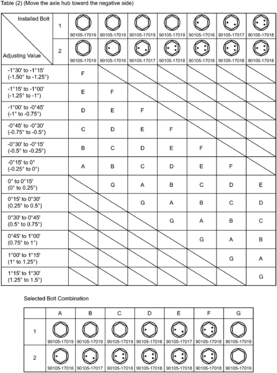
4 (g) Install the front wheel. Torque: 103 N m (1050 kgf cm, 76ft lbf) (h) Check the camber. If the measured value is not within the specification, calculate the required adjustment amount using the formula below. Camber adjustment amount = center of the specified range - measured value Check the combination of the installed bolts. Select appropriate bolts from the tables below to adjust the camber to the specified values. HINT: Try to adjust the camber to the center of the specified values. MOVE THE AXLE HUB TOWARD (+) IN STEP B Refer to table (1) (Move the axle hub toward the positive side) MOVE THE AXLE HUB TOWARD (-) IN STEP B Refer to table (2) (Move the axle hub toward the negative side)

5

6
7 Replace the nut with a new one when replacing the bolt. The body and suspension may be damaged if the camber is not correctly adjusted according to the tables above. (i) Repeat the steps mentioned above. In Step A, replace 1 or 2 selected bolts. HINT: Replace one bolt at a time when replacing both bolts. 5. INSPECT TOE-IN Inspect while the vehicle is unloaded. (a) Bounce the vehicle up and down at the corners to stabilize the suspension. (b) Release the parking brake and move the shift lever to N. (c) Push the vehicle straight ahead approximately 5 m (16.4 ft.). (Step C) (d) Put tread center marks on the rearmost points of the front wheels and measure the distance between the marks (dimension B). *1 Tread Center Mark *2 Dimension B (e) Slowly push the vehicle straight ahead to cause the front wheels to rotate 180 using the front tire valve as a reference point. HINT: Do not allow the wheels to rotate more than 180. If the wheels rotate more than 180, perform the procedure from Step C again. (f) Measure the distance between the tread center marks on the front side of the wheels (dimension A). Front of the Vehicle
. (Step C) (d) Put tread center marks on the rearmost points of the front wheels and measure the distance between the marks (dimension B).")
* HINT: Measure \"B - A\" only when \"C + D\" cannot be measured. If the toe-in is not within the specified range, adjust it at the rack ends. 6.")
8 *1 *2 Dimension A To-in (Unloaded Vehicle) SPECIFIED CONDITION C + D: 0 12' +/- 0 12' (0.20 +/ ) C + D: 0 18' +/- 0 12' (0.30 +/ )* B - A: 2.0 +/- 2.0 mm ( / in.) B - A: 3.0 +/- 2.0 mm ( / in.)* HINT: Measure "B - A" only when "C + D" cannot be measured. If the toe-in is not within the specified range, adjust it at the rack ends. 6. ADJUST TOE-IN (a) Make sure that the thread length of the right and left rack ends are approximately the same. *1 Thread Length Standard difference: 1.5 mm ( in.) or less (b) Remove the boot clips. (c) Loosen the tie rod end lock nuts. *1 Loosen *2 Turn (d) Adjust the rack ends if the difference in thread length between the right and left rack ends is not within the specified range. (1) Extend the shorter rack end if the measured toe-in deviates toward the outer-side. (2) Shorten the longer rack end if the measured toe-in deviates toward the inner-side.
 or less (b) Remove the boot clips. (c) Loosen the tie rod end lock nuts.")
9 (e) Turn the right and left rack ends by an equal amount to adjust the toe-in to the center value. (f) Make sure that the thread lengths of the right and left rack ends are the same. (g) Tighten the tie rod end lock nuts. Torque: 74 N m (755 kgf cm, 55ft lbf) (h) Place the boots on the seats and install the clips. HINT: Make sure that the boots are not twisted. 7. INSPECT WHEEL ANGLE *1 Front of the Vehicle *2 Inside *3 Outside (a) Put tread center marks on the rearmost points of a turning radius gauge. (b) Turn the steering wheel to the left and right full lock positions, and measure the turning angle. Inspect while the vehicle is unloaded. Wheel Angle (Unloaded Vehicle): TIRE SIZE INSIDE WHEEL OUTSIDE WHEEL REFERENCE 195/65R ' +/- 2 ( /- 2 ) 37 42' +/- 2 ( /- 2 )* 33 50' (33.83 ) 32 13' (32.22 )* 215/45R ' +/- 2 ( /- 2 ) 31 56' (31.93 ) If the angles are not as specified, check and adjust the right and left rack end lengths. 8. PLACE FRONT WHEELS FACING STRAIGHT AHEAD 9. PERFORM YAW RATE AND ACCELERATION SENSOR CALIBRATION. 10. PERFORM INITIALIZATION (w/ Height Control Sensor)
: TIRE SIZE INSIDE WHEEL OUTSIDE WHEEL REFERENCE 195/65R15 40 50' +/- 2 (40.83 +/- 2 ) 37 42' +/- 2 (37.70 +/- 2 )* 33 50' (33.83 ) 32 13' (32.")
10 Some systems need to be initialized after the wheel alignment is adjusted.

FRONT WHEEL ALIGNMENT
 66 RONT SUSPNSION DJUSTMNT. INSPCT TIR (S P 8) 60I50 ront: Rear:. MSUR VHICL HIHT Vehicle height: ront ( ) Rear (D C) 95 mm (3.74 in.) 6 mm (.44 in.) Measuring points: : round clearance of front wheel
FRONT WHEEL ALIGNMENT
 RONT SUSPNSION RONT WHL LINMNT 67 RONT WHL LINMNT JUSTMNT. INSPCT TIR (S P 67 ) 60H703. MSUR VHICL HIHT Vehicle height: ront Rear C 4W C C 373 0. mm (4.73 in.) 40.5 mm (.59 in.) 4W 0. mm (4.33 in.) 30.5
WHEEL ALIGNMENT 4WD SA 6
 SA6 WHEEL ALIGNMENT 4WD 1. MAKE FOLLOWING CHECKS AND CORRECT ANY PROBLEMS (a) Check the tires for wear and proper inflation. Cold tire inflation pressure: See page A25 (b) Check the wheel runout. Lateral
WHEEL ALIGNMENT SPECIFICATIONS & PROCEDURES
 WHEEL ALIGNMENT SPECIFICATIONS & PROCEDURES For 1234 1992 WHEEL ALIGNMENT Subaru Specifications & Procedures Justy, Legacy, Loyale, SVX * PLEASE READ THIS FIRST * NOTE: Prior to performing wheel alignment,
MEASURING WHEEL ALIGNMENT
 MEASURING WHEEL ALIGNMENT 2003-04 WHEEL ALIGNMENT Specifications & Procedures - Hummer - H2 Steering and vibration complaints are not always the result of improper alignment. One possible cause is wheel
FRONT SUSPENSION Click on the applicable bookmark to selected the required model year
 FRONT SUSPENSION 33A-2 FRONT SUSPENSION General Information GENERAL INFORMATION 33200010105 The front suspension on 2WD vehicles is an independent suspension system having the double wishbone combined
http://localhost/vida/jsp/information/xml/xmldocprintpreview.jsp
 Page 1 of 7 60: Wheel alignment V70 XC (01-) / XC70 (-07), 2001, B5244T3, AW50/51 AWD, L.H.D, YV1SZ58D811036138, 036138 5/4/2014 PRINT 60: Wheel alignment Wheel alignment, checking / adjusting Note! For
SECTION 2B WHEEL ALIGNMENT TABLE OF CONTENTS
 SECTION 2B WHEEL ALIGNMENT TABLE OF CONTENTS Description and Operation... 2B2 Four Wheel Alignment... 2B2 Toein... 2B2 Caster... 2B2 Camber... 2B2 Diagnostic Information and Procedures... 2B3 Tire Diagnosis...
Prepared by Graham from SuperPro August 2011
 Understanding di Steering and Wheel Alignment Angles Prepared by Graham from SuperPro August 2011 Remember:- Tyre Wear Patterns Tell The Technician A Story Provide Vital Information For Determining Final
SELF-STEERING AXLE TABLE OF CONTENTS
 SELF-STEERING AXLE TABLE OF CONTENTS Section 1 - Introduction Section 2 - Pre-Installation Check List Section 3 - Ride Height Adjustments Section 4 - Suspension Mount Section 5 - Axle Mount Section 6 -
REAR SHOCK ABSORBER WITH COIL SPRING
 278 OVERHAUL COMPONENTS: see page 272. 1. REMOVE TONNEAU COVER ASSY (SEE PAGE 7627) 2. REMOVE DECK BOARD SUBASSY (SEE PAGE 7627) 3. REMOVE BACK DOOR SCUFF PLATE (SEE PAGE 7627) 4. REMOVE DECK FLOOR BOX
WHEEL ALIGNMENT SPECIFICATIONS & PROCEDURES
 WHEEL ALIGNMENT SPECIFICATIONS & PROCEDURES 1998 Mitsubishi Montero 1997-98 WHEEL ALIGNMENT Mitsubishi - Specifications & Procedures Diamante, Eclipse, Galant, Mirage, Montero, Montero Sport, 3000GT RIDING
4-Wheel Alignment Steering and Suspension Diagnosis
 JOB SHEET A4E3: Start Date: Name: End Date: Make: Model: Year: VIN: Mileage: Learning Objective/NATEF task Check and adjust front and rear wheel camber; perform necessary action. o NATEF task A4/E3, P1.
LIFT-505. BMF Lift Kit. Yamaha Drive Gas or Electric. Installation Instructions
 LIFT-505 BMF Lift Kit Yamaha Drive Gas or Electric Installation Instructions Contents of LIFT-505 Yamaha Drive BMF Lift Kit: a (1 ea.) BMF A-Arm Assembly b (1 ea.) Driver Side Shock Tower c (1 ea.) Passenger
STEERING HANDLEBAR/FRONT WHEEL/ FRONT SHOCK ABSORBER
 14 14 STEERING HANDLEBAR/FRONT WHEEL/ SCHEMATIC DRAWING ------------------------------------------------- 14-1 SERVICE INFORMATION------------------------------------------------ 14-2 TROUBLESHOOTING-----------------------------------------------------
1993 SUSPENSION Volkswagen Front. EuroVan
 Article Text ARTICLE BEGINNING 1993 SUSPENSION Volkswagen Front EuroVan DESCRIPTION FWD independent suspension is an double-wishbone type with torsion bars mounted on upper control arm. Wheel is supported
Technical Service Bulletin
 Subject FOUR WHEEL ALIGNMENT - EZ CAM TM XR CAMBER ANGLE ADJUSTING BOLTS Date Model [X] PARTS MANAGER JANUARY, 2008 2003-2008 TIBURON [X] TECHNICIAN CIRCULATE TO: [ ] GENERAL MANAGER [X] SERVICE ADVISOR
Volkswagen Phaeton 44-2 Wheel and tire mounting Wheel mounting Mounting tires Pressing off tires Dismounting tires Mounting tires
 Wheel and tire mounting Стр. 1 из 1 Volkswagen Phaeton 44-2 Wheel and tire mounting Wheel mounting Wheel bolt to hub Torque specification: 120 Nm Mounting tires The tires are installed as usual, but note
SCION tc 2005-2008 COIL OVER SUSPENSION Preparation
 SCION tc 2005-2008 COIL OVER SUSPENSION Preparation Part Number: PTR11-21070 NOTE: Part number of this accessory may not be the same as the part number shown. Kit Contents: Item # Quantity Reqd. Description
(A4) Suspension and Steering Sample Questions and Answers
 Suspension and Steering Sample Questions and Answers") (A4) Suspension and Steering Sample Questions and Answers Answers to these questions are found beginning on page 4 of this document 1. Two technicians are discussing the replacement of an inner tie rod
(A4) Suspension and Steering Sample Questions and Answers Answers to these questions are found beginning on page 4 of this document 1. Two technicians are discussing the replacement of an inner tie rod
A Short Course on Wheel Alignment
 A Short Course on Wheel Alignment In its most basic form, a wheel alignment consists of adjusting the angles of the wheels so that they are perpendicular to the ground and parallel to each other. The purpose
SUBJECT: Special Offset Ball Joint - Allows Adjustment To Caster And Camber Angles
 NUMBER: 02-001-02 GROUP: Suspension DATE: Jun. 10, 2002 This bulletin is supplied as technical information only and is not an authorization for repair. No part of this publication may be reproduced, stored
6 inch A-Arm Lift Kit WARNING: 16-018/16-019. installation instructions. will fit CLUB CAR DS. included:
 Revised May 205 6-08/6-09 6 inch A-Arm Lift Kit will fit CLUB CAR DS installation instructions included: Rear Lift Blocks Main Suspension Assembly Spindles A-Arms Rear Shock Mounting Plates U-Bolts WARNING:
SUSPENSION DIAGNOSIS
 SECTION 2A SUSPENSION DIAGNOSIS TABLE OF CONTENTS Diagnosis... 2A-2 General Diagnosis... 2A-2 Hub and Bearing... 2A-7 2A-2 SUSPENSION DIAGNOSIS DIAGNOSIS GENERAL DIAGNOSIS Problems in the steering, the
2011-14 F250 6 RADIUS ARM KIT
 92154000 Thank you for choosing Rough Country for your suspension needs. 2011-14 F250 6 RADIUS ARM KIT Rough Country recommends a certified technician installs this system. In addition to these instructions,
2. Wheel Alignment S202116
 Front Suspension WHEEL ALIGNMENT 2. Wheel Alignment S202116 A: INSPECTION S202116A10 Check, adjust and/or measure wheel alignment in accordance with procedures indicated in figure: B4M1088A FS-6 WHEEL
Service Bulletin Trucks Date Group No. Page
 Volvo Trucks North America, Inc. Greensboro, NC USA Replaces Service Bulletin 601 06 dated 03.98. Service Bulletin Trucks Date Group No. Page 9.2000 601 006 1(8) Wheel Alignment Steer and Drive Axles VN,
Volkswagen Corrado 1990-1994 Suspension Wheels -Tires Wheel Alignment (Page GR-44)
") Wheels -Tires Wheel Alignment (Page GR-44) Front wheel camber adjusting Rear wheel toe determining Snow tires size Vibrations eliminating Wheel alignment data (4 cylinder) data (6 cylinder) Wheels - Tires,
Wheels -Tires Wheel Alignment (Page GR-44) Front wheel camber adjusting Rear wheel toe determining Snow tires size Vibrations eliminating Wheel alignment data (4 cylinder) data (6 cylinder) Wheels - Tires,
DO NOT attempt to repair hub and wheel bearing assembly.
 Page 1 of 6 HUB & WHEEL BEARINGS (WITH PULSE VACUUM HUBLOCK) DO NOT attempt to repair hub and wheel bearing assembly. Removal DO NOT remove hub lock assembly by prying on hub lock legs. This can crack
REAR AXLE 27-1 CONTENTS 27109000161 ON-VEHICLE SERVICE... 3 GENERAL INFORMATION... 2 SERVICE SPECIFICATIONS... 2 SPECIAL TOOLS... 2 REAR AXLE HUB...
 27-1 REAR AXLE CONTENTS 27109000161 GENERAL INFORMATION... 2 SERVICE SPECIFICATIONS... 2 SPECIAL TOOLS... 2 ON-VEHICLE SERVICE... 3 Wheel Bearing Axial Play Check... 3 Wheel Bearing Rotary-Sliding Resistance
INSTALLATION INSTRUCTIONS COMPETITION SERIES COILOVER SUSPENSION SYSTEM 03+ Scion xb
 INSTALLATION INSTRUCTIONS COMPETITION SERIES COILOVER SUSPENSION SYSTEM 03+ Scion xb NOTE: Progress Technology products should only be installed by a qualified licensed mechanic experienced in the installation
Mazda North American Operations Irvine, CA 92618-2922
 Service Bulletin Mazda North American Operations Irvine, CA 92618-2922 Subject: STEERING WHEEL OFF CENTER Bulletin No: 02-005/10 MULTI-MODEL - STEERING WHEEL OFF CENTER BULLETIN NOTE This bulletin supersedes
SUSPENSION AND STEERING OVERVIEW
 SUSPENSION SUSPENSION AND STEERING OVERVIEW The S40/V50 has a wide track and a long wheelbase for its relative size and weight. This gives the car stable and predictable driving characteristics. It also
Table of Contents. Suspension Systems
 Table of Contents Subject Page Purpose of the System... 3 Basic Suspension Geometry... 4 Caster...4 Camber...5 Toe...6 Steering Roll Radius...7 Steering Axis Inclination....8 Toe-out on Turns...9 Geometric
SUSPENSION 2-1 SUSPENSION TABLE OF CONTENTS
 PL SUSPENSION 2-1 SUSPENSION TABLE OF CONTENTS page WHEEL ALIGNMENT... 1 FRONT SUSPENSION... 9 page REAR SUSPENSION... 35 WHEEL ALIGNMENT TABLE OF CONTENTS page DESCRIPTION AND OPERATION WHEEL ALIGNMENT...1
TECHNICAL BULLETIN. Meritor WABCO Cab Leveling Valves and Chassis Leveling Valves. How the Cab Leveling and Chassis Leveling Valves Work
 Revised 02-00 TECHNICAL BULLETIN Meritor WABCO Cab Leveling Valves and Chassis Leveling Valves This technical bulletin covers both cab and chassis leveling valves manufactured by Meritor WABCO. While the
Wheel Alignment And Diagnostic Angles (STE04)
") Module 1 Alignments Wheel Alignment And Diagnostic Angles (STE04) A. Alignments 2. Conditions Requiring An Alignment 3. Conditions Requiring An Alignment (cont d) 4. Why We Do Checks/Alignments 5. Alignment
Module 1 Alignments Wheel Alignment And Diagnostic Angles (STE04) A. Alignments 2. Conditions Requiring An Alignment 3. Conditions Requiring An Alignment (cont d) 4. Why We Do Checks/Alignments 5. Alignment
rarecorvettes.com, [email protected], (831) 475-4442 Pacific Time Zone
 475-4442 Pacific Time Zone") INTRODUCTION TO WHEEL ALIGNMENT A SHORT COURSE ON WHEEL ALIGNMENT, FRONT AND REAR PREPARED FOR THE N.C.R.S. NATIONAL CONVENTION JUNE 29 TO JULY 5, 2012 by: JOE CALCAGNO, RARE CORVETTES rarecorvettes.com,
INTRODUCTION TO WHEEL ALIGNMENT A SHORT COURSE ON WHEEL ALIGNMENT, FRONT AND REAR PREPARED FOR THE N.C.R.S. NATIONAL CONVENTION JUNE 29 TO JULY 5, 2012 by: JOE CALCAGNO, RARE CORVETTES rarecorvettes.com,
AXLE SHAFTS - FRONT. 1993 Toyota Celica DESCRIPTION REMOVAL, DISASSEMBLY, REASSEMBLY & INSTALLATION. 1993 DRIVE AXLES Toyota FWD Axle Shafts
 AXLE SHAFTS - FRONT 1993 Toyota Celica 1993 DRIVE AXLES Toyota FWD Axle Shafts Toyota; Celica DESCRIPTION Axle shafts transfer power from transaxle to driving wheels. All axle shafts consist of a shaft
Front axle components, overview
 just a test. Front axle components, overview 40-1 General Information Load bearing components and parts of the suspension must not be welded or straightened. Vehicles without drive axle must not be moved,
HOME ALIGNMENT OF PORSCHE 914 FOR COMPETITION OR STREET. Complete Step by Step Guide to Alignment
 HOME ALIGNMENT OF PORSCHE 914 FOR COMPETITION OR STREET Complete Step by Step Guide to Alignment How to adjust: A. Level and Rake Car p. 4 B. Camber p. 6 C. Caster p. 7 D. Toe p. 8 E. Corner Balance p.
»Product» Safety Warning
 C1200 Installation Instructions 2007-2016 Chevy/GM 1500 2/4wd 2" Strut Spacer Lift Read and understand all instructions and warnings prior to installation of product and operation of vehicle. Zone Offroad
Tooling List 17mm Socket 17mm Wrench 24mm Wrench 26mm Wrench 3/8 Drive Ratchet Torque Wrench
 Thank you for purchasing the CorkSport Rear Adjustable Camber Arms. By replacing your OEM camber arms with the CorkSport Adjustable Camber Arms, you will be able to dial in your suspension with +/- 5 degrees
OPTO-PLUS 204. Type DSX2
 1 OPTO-PLUS 204 Type DSX2 OPTO-ELECTRONIC LASER ALIGNER Operators manual 2 Operators manual for OPTO-PLUS wheel aligner Model 204 Type DSX2 (Dual Sensor Doubble Laser) INDEX Accessories and specifications
Freightliner AirLiner Suspension 32.05
 Freightliner irliner Suspension 3.05 Ride Height djustment NOTICE Failure to adjust the suspension ride height could adversely affect driveline angles. lso, if the air springs are set too high, the driver
STEERING SYSTEM - POWER
 STEERING SYSTEM - POWER 1990 Nissan 240SX 1990 STEERING Nissan - Power Rack & Pinion Axxess, Maxima, Pulsar NX, Sentra, Stanza, 240SX, 300ZX DESCRIPTION The power steering system consists of a rack and
Recall R136 Front Lower Ball Joints Check Torque or Replace
 SERVICE DATE /00 Amended /00 TECHNICAL BULLETIN Recall R6 Front Lower Ball Joints Check Torque or Replace MODEL VIN Remove and destroy Bulletin S04-R6, dated /00. Replace with this Bulletin. Revisions
WHEEL ALIGNMENT SPECIFICATIONS & PROCEDURES
 WHEEL ALIGNMENT SPECIFICATIONS & PROCEDURES 2001 Chevrolet Camaro 2000-01 WHEEL ALIGNMENT Specifications & Procedures Cars - Except Saturn IDENTIFICATION MODEL IDENTIFICATION Body Code (1) Model "C"...
TABLE OF CONTENTS. Page 1
 TABLE OF CONTENTS CONGRATULATIONS: Easy Start Guide for the Technician... 2 Laser Toe Gauges... 4 Hardware Connections... 5 Printer Connection... 6 Data Accumulator Features... 7 Batteries - Read Out &
Basic Wheel Alignment Fundamentals
 Specialty Products Company Basic Wheel Alignment Fundamentals Wheel alignment technology advances continuously with the introduction of new makes and models of vehicles, engines, transmissions/ transaxles,
Provide a WELCOME, Avoid put downs and bad jokes.
 Automotive Steering, Suspension, & Alignment Chapter 17 WHEEL ALIGNMENT PRINCIPLES Opening Your Class KEY ELEMENT Introduce Content Motivate Learners State the learning objectives for the chapter or course
CorkSport Mazdaspeed 6 Rear Sway Bar 2006-2007 Mazdaspeed 6
 CorkSport Mazdaspeed 6 Rear Sway Bar 2006-2007 Mazdaspeed 6 Pre-Installation Notes: The CorkSport Rear Sway Bar is a great addition to improving the handling performance to the Mazdaspeed 6. It will minimize
2008 ACCORD - Front Knuckle/Hub/Wheel Bearing Replacement (page 18-13)
") 2008 ACCORD - Front Knuckle/Hub/Wheel Bearing Replacement (page 18-13) Exploded View Special Tools Required Ball joint remover, 28 mm 07MAC-SL0A202 Hub dis/assembly tool 07GAF-SD40100 Bearing driver attachment,
2008 ACCORD - Front Knuckle/Hub/Wheel Bearing Replacement (page 18-13) Exploded View Special Tools Required Ball joint remover, 28 mm 07MAC-SL0A202 Hub dis/assembly tool 07GAF-SD40100 Bearing driver attachment,
Verify caster, camber and toe-in are correct before proceeding.
 If rotating the tie rod end 360 degrees changes the toe-in too much, use the rack tie rod to make smaller adjustments. Put the tie rod end in the steering arm and snug the castle nut before adjusting.
12. REAR WHEEL/BRAKE/SUSPENSION
 12 12 12-0 SERVICE INFORMATION... 12-1 REAR BRAKE... 12-5 TROUBLESHOOTING... 12-2 REAR SHOCK ABSORBER... 12-8 REAR WHEEL... 12-3 REAR FORK... 12-9 SERVICE INFORMATION GENERAL INSTRUCTIONS When installing
ReadyLift (Part# 66-5075) Strut Extension, Installation Instructions Toyota Tundra New Body Style 2WD & 4WD
 Strut Extension, Installation Instructions Toyota Tundra New Body Style 2WD & 4WD") SAFETY WARNING: recommends this system be installed by a professional technician. In addition to these instructions, professional knowledge of disassembly/ reassembly procedures and post installation checks
SAFETY WARNING: recommends this system be installed by a professional technician. In addition to these instructions, professional knowledge of disassembly/ reassembly procedures and post installation checks
TL-12 Passenger Car Alignment System
 Operation and Service Manual Laser Guided Wheel Alignment System TL-12 Passenger Car Alignment System 8231 Blaine Road Blaine, WA 98230 360-371-0552 360-371-0553 fax 800-496-3777 toll free www.tru-line.net
INSTALLATION INSTRUCTIONS. 6111 Air Spring Kit 2011+ Ford F250/F-350 Single Wheel 2WD 2011+ Ford F350 Dually 2WD IMPORTANT NOTES
 INSTALLATION INSTRUCTIONS 6111 Air Spring Kit 2011+ Ford F250/F-350 Single Wheel 2WD 2011+ Ford F350 Dually 2WD Thank you for purchasing a quality Hellwig Product. PLEASE READ THIS INSTRUCTION SHEET COMPLETELY
MM Adjustable Tie-Rod Ends (MMTR-2, -4, -7)
") 3430 Sacramento Dr., Unit D San Luis Obispo, CA 93401 Telephone: 805/544-8748 Fax: 805/544-8645 www.maximummotorsports.com MM Adjustable Tie-Rod Ends (MMTR-2, -4, -7) PLEASE NOTE: The use of 1996-2004
3430 Sacramento Dr., Unit D San Luis Obispo, CA 93401 Telephone: 805/544-8748 Fax: 805/544-8645 www.maximummotorsports.com MM Adjustable Tie-Rod Ends (MMTR-2, -4, -7) PLEASE NOTE: The use of 1996-2004
WHEEL ALIGNMENT. Straight advice, specialists you understand and...
 WHEEL ALIGNMENT Straight advice, specialists you understand and... WHEEL ALIGNMENT If your steering wheel vibrates at certain speeds, or the steering feels heavier than before; or if your tyres seem to
Volkswagen Jetta, Golf, GTI 1999, 2000 Brake System 46 Brakes - Mechanical Components (Page GR-46)
") 46 Brakes - Mechanical Components (Page GR-46) Front brakes Brake pads, removing and installing Brake pads, removing and installing FN 3 brake caliper, servicing FS III brake caliper, servicing Rear wheel
46 Brakes - Mechanical Components (Page GR-46) Front brakes Brake pads, removing and installing Brake pads, removing and installing FN 3 brake caliper, servicing FS III brake caliper, servicing Rear wheel
MUSTANG II IFS COMPLETE PARTS PACKAGE
 MUSTANG II IFS COMPLETE PARTS PACKAGE Your Southern Rods & Parts Mustang II IFS Parts Package contains the following items: 1 pr) Upper Control Arms (2023) 1) Upper Arm Bolt Kit (MP-001-A) 1 pr) Lower
TRUCKCAM FACTORY SYSTEMS AXLE ALIGNMENT
 TRUCKCAM FACTORY SYSTEMS AXLE ALIGNMENT INTRODUCING: TRUCKCAM AXLE ALIGNMENT SYSTEM THIS SYSTEM IS DESIGNED for axle manufacturers to pre-align toe-in. The efficient and durable design of the system allows
16 April 2012 1032011-F 1994-2002 Dodge Adjustable Track bar with Relocation Bracket 1
 16 April 2012 1032011-F 1994-2002 Dodge Adjustable Track bar with Relocation Bracket 1 BD Adjustable Track Bar w/bracket Dodge 2500-3500 4WD Models 1994-2002 Dodge 1500 4WD Model 1994-2001 P/N# 1032011-F
Competition 4 & 6 suspension Lift Toyota Landcruiser & nissan patrol
 Competition 4 & 6 suspension Lift Toyota Landcruiser & nissan patrol Competition suspension Product Guidelines Guidelines for sale and recommendation of 4 (100mm) and 6 (150mm) Lifts for Toyota Landcruiser
Owner s Manual Read and keep this manual. Patents World Wide
 Owner s Manual Read and keep this manual. Patents World Wide S & S Industries, Inc., Sarasota, FL, USA www.trail-gator.com Copyright 2008 All Rights Reserved The following manual is provided to assist
Rating when used as a weight carrying hitch without spring bars:
 BOLT-TOGETHER WEIGHT DISTRIBUTING HITCH SYSTEM Rating when used as a weight distributing hitch with spring bars: Part Number 48051 4805 48053 48054 Max Tongue Weight 550 Ibs. 750 Ibs. 1000 Ibs. 1400 lbs.
Align it Right! How to properly align your GMC yourself right in your own driveway. By Jerry Work GMCWS rally Casa de Fruita, CA Spring 2012
 Align it Right! How to properly align your GMC yourself right in your own driveway By Jerry Work GMCWS rally Casa de Fruita, CA Spring 2012 TEXT & PHOTOS BY JERRY WORK EXCEPT AS NOTED Simple concepts,
BEE LINE COMPANY TOTAL VEHICLE WHEEL ALIGNMENT AND THE BENEFITS OF CAMBER CORRECTION
 BEE LINE COMPANY TOTAL VEHICLE WHEEL ALIGNMENT AND THE BENEFITS OF CAMBER CORRECTION 2700 62nd Street Court, P.O. Box 130 Bettendorf, Iowa 52722 Phone: 800-728-7828 Fax: 563-332-6517 Website: www.beeline-co.com
John Cooper Works Tuning. Installation Instructions.
 John Cooper Works Tuning. Installation Instructions. Retrofit - John Cooper Works Sport Suspension MINI ONE (R 56) MINI COOPER (R 56) MINI COOPER S (R 56) Retrofit kit No. 33 50 0 429 708 Retrofit kit,
Section A. GENERAL INFORMATION
 Section A. GENERAL INFORMATION I. Description The information and instructions for attaching the sidecar to the right-hand side of the motorcycle are contained in this handbook and must be carefully observed.
Oregon Fuel Injection
 Corporate Office: P.O. Box 21121, VE Pump Removal and Installation Cummins Lock Timed Applications Removal Clean the exterior of the injection pump and mounting surfaces. 1. Disconnect the fuel return
ARVINMERITOR UNITIZED FRONT WHEEL HUB INSPECTION AND MAINTENANCE
 SERVICE BULLETIN (Also applies to Mack Trucks Australia) NUMBER: SB-423-002 DATE: 8/23/02 MODEL: All with FF981 Front Axle ARVINMERITOR UNITIZED FRONT WHEEL HUB INSPECTION AND MAINTENANCE The ArvinMeritor
M113 VEHICLE FAMILY RUBBER TRACK INSTALLATION INSTRUCTIONS SOUCY TRACK SYSTEM 04-M113-1ENS (SPLIT IDLER) Litho d in Canada 1 04-M113-1ENS
 Litho d in Canada 1 04-M113-1ENS") M113 VEHICLE FAMILY RUBBER TRACK INSTALLATION INSTRUCTIONS (SPLIT IDLER) 1 # TABLE OF CONTENTS List of parts and tools................................................3 Installation of complete kit...................................................5
M113 VEHICLE FAMILY RUBBER TRACK INSTALLATION INSTRUCTIONS (SPLIT IDLER) 1 # TABLE OF CONTENTS List of parts and tools................................................3 Installation of complete kit...................................................5
Rear wheel brakes, servicing. Стр. 1 из 45. Note:
 Volkswagen Touareg - Rear wheel brakes, servicing Стр. 1 из 45 46-2 Rear wheel brakes, servicing Rear brakes, FN 44 brake caliper, servicing Note: After replacing brake pads, depress brake pedal firmly
AXLE SHAFTS - FRONT. 1998 Pontiac Bonneville MODEL IDENTIFICATION DESCRIPTION & OPERATION TROUBLE SHOOTING REMOVAL & INSTALLATION
 AXLE SHAFTS - FRONT 1998 Pontiac Bonneville 1998-99 DRIVE AXLES FWD Axle Shafts - Cars - "C", "G" & "H" Bodies GM Aurora, Bonneville, Eighty Eight, LeSabre, LSS, Park Avenue, Regency, Riviera MODEL IDENTIFICATION
INSTALLATION INSTRUCTIONS. 6108 Air Spring Kit 2011+ Ford F250 Single Wheel 4WD 2011+ Ford F350 Dually 4WD (2011 F350 Single Wheel 4WD use p/n 6113)
") INSTALLATION INSTRUCTIONS 6108 Air Spring Kit 2011+ Ford F250 Single Wheel 4WD 2011+ Ford F350 Dually 4WD (2011 F350 Single Wheel 4WD use p/n 6113) Thank you for purchasing a quality Hellwig Product. PLEASE
INSTALLATION INSTRUCTIONS 6108 Air Spring Kit 2011+ Ford F250 Single Wheel 4WD 2011+ Ford F350 Dually 4WD (2011 F350 Single Wheel 4WD use p/n 6113) Thank you for purchasing a quality Hellwig Product. PLEASE
Drive shaft, servicing
 Volkswagen Passat B6 - Drive shaft, servicing Стр. 1 из 41 40-7 Drive shaft, servicing Drive shafts, overview I - Assembly overview: Drive axle with CV joint VL100 40-7, Drive axle with CV joint VL100,
2003 Audi A4. AUDI' '3.0L V6 - AVK Engine - A4 & A6
 Installation (A4) CAUTION: Before installation, ensure camshafts are aligned, crankshaft is locked in place and camshaft gear bolts are loose as described in removal procedures. When turning camshaft,
Ford F-250 / 350 2-1/2 Coil Kit. Ford F-250, F350 2011-2015. Part#: 013255
 Part#: 013255 Ford F-250 / 350 2-1/2 Coil Kit Ford F-250, F350 2011-2015 Rev.040815 491 W. Garfield Ave., Coldwater, MI 49036. Phone: 517-279-2135 Web/live chat: www.bds-suspension.com. E-mail: [email protected]
3. INSPECTION/ADJUSTMENT
 3 3 INSPECTION/ADJUSTMENT SERVICE INFORMATION-------------------------------------------------- 3-1 MAINTENANCE SCHEDULE (XCITING 500) ------------------------- 3-3 MAINTENANCE SCHEDULE (XCITING 250) -------------------------
2003 ACCORD - Automatic Transmission Removal
 2003 ACCORD - Automatic Transmission Removal Special Tools Required Engine support hanger, A and Reds AAR-T-12566 Engine hanger balancer bar VSB02C000019 Front subframe adapter VSB02C000016 These special
Unit: mm(in) Item Standard value Service limit Axle shaft run out - 0.2(0.008)
 Item Standard value Service limit Axle shaft run out - 0.2(0.008)") Rear Wheel/Brake/Suspension 13. Rear Wheel/Brake/Suspension Service Information 13-1 Troubleshooting 13-2 Rear Wheel 13-3 Rear Cushion 13-4 Rear Swing Arm 13-7 Service Information General Safety If the
Rear Wheel/Brake/Suspension 13. Rear Wheel/Brake/Suspension Service Information 13-1 Troubleshooting 13-2 Rear Wheel 13-3 Rear Cushion 13-4 Rear Swing Arm 13-7 Service Information General Safety If the
WARNING TO END USER, INSTALLER AND SELLER OF THIS PART!
 WARNING TO END USER, INSTALLER AND SELLER OF THIS PART! By installing this part you are accepting full responsibility and liability for proper wheel and tire fitment after installation. It is the installer
Suspension and Steering Systems Operation. The Steering/Suspension System (Overview)
") Suspension and Steering Systems Operation Below is an overview of the suspension and steering systems The Steering/Suspension System (Overview) "Suspension," when discussing cars, refers to the use of
Suspension and Steering Systems Operation Below is an overview of the suspension and steering systems The Steering/Suspension System (Overview) "Suspension," when discussing cars, refers to the use of
M-2004-MBA Brake Duct Kit 2013 BOSS 302, Mustang GT and California Special INSTALLATION INSTRUCTIONS
 Please visit www.fordracingparts.com for the most current instruction information.!!! PLEASE READ ALL OF THE FOLLOWING INSTRUCTIONS CAREFULLY PRIOR TO INSTALLATION. AT ANY TIME YOU DO NOT UNDERSTAND THE
Front brakes (FN- 3), servicing
, servicing") j a t Front brakes (FN- 3), servicing 46-1 Front brakes, servicing Note: Install complete repair kit. After replacing brake pads and before moving vehicle, depress brake pedal several times firmly to properly
j a t Front brakes (FN- 3), servicing 46-1 Front brakes, servicing Note: Install complete repair kit. After replacing brake pads and before moving vehicle, depress brake pedal several times firmly to properly
REYCOGRANNING AIR SUSPENSIONS
 REYCOGRANNING AIR SUSPENSIONS INDEPENDENT FRONT SUSPENSION & TRAILING BEAM REAR SUSPENSION IFS1200LP & RD1900/2300SLP SERVICE MANUAL D9921 Rev. C 08/08/01 Service Notes This Service Manual describes the
2010 APPLICATION REFERENCE GUIDE
 2010 APPLICATION REFERENCE GUIDE INDEX QUALITY POLICY 2 ERGO ASSIST STANDARD 4-13 CUSTOM 14-18 END EFFECTORS 19-24 LIFT ASSIST 25-41 FIXTURED TOOLS 42-53 FIXTURES 54-63 ASSEMBLY TABLES 64-72 CARTS/ DUNNAGE
ASSEMBLY MANUAL SE-4S35
 Automatic drive ASSEBLY ANUAL SE-4S35 AI-4S35 SG-4R35 Battery box otor unit Inter-4 hub CONTENTS WARNING 1 INSTALLATION CONITIONS Battery box Speed sensor Cable lengths and diameters otor unit Recommended
READ AND UNDERSTAND ALL INSTRUCTIONS AND WARNINGS PRIOR TO INSTALLATION OF SYSTEM AND OPERATION OF VEHICLE.
 491 W. Garfield Ave., Coldwater, MI 49036 Phone: 517-279-2135 Web/live chat: www.bds-suspension.com E-mail: [email protected] Product: GM Leaf Spring READ AND UNDERSTAND ALL INSTRUCTIONS AND
13. REAR WHEEL/BRAKE/SUSPENSION
 13. REAR WHEEL/BRAKE/SUSPENSION 13 3.5~4.5kg-m 8.0~10.0kg-m 0.8~1.2kg-m 3.0~4.0kg-m 2.4~3.0kg-m 3.5~4.5kg-m 6.0~8.0kg-m 13-0 13. REAR WHEEL/BRAKE/SUSPENSION 13 REAR WHEEL/BRAKE/SUSPENSION SERVICE INFORMATION...
Adjustment Data MAZDA - 626-2.0 Comprex D - RF-CX
 Adjustment Data MAZDA - 626-2.0 Comprex D - RF-CX Engine (general) Engine code RF Capacity 1998 (cc) Idle speed 725 ± 25 Valve clearance Valve clearance Cold Inlet 0.25 (mm) Exhaust 0.35 (mm) Compression
Linear Motion vs. Rotational Motion
 Linear Motion vs. Rotational Motion Linear motion involves an object moving from one point to another in a straight line. Rotational motion involves an object rotating about an axis. Examples include a
INSIDE ENGINE COMPARTMENT TOYOTA AIR CONDITIONING ENGLISH EUROPE,GENERAL,AUSTRALIA
 INSIDE ENGINE COMPARTMENT TOYOTA AIR CONDITIONING ENGLISH EUROPE,GENERAL,AUSTRALIA INTRODUCTION IMPORTANT NOTICE This manual has been designed for technicians who are qualified and educated in the proper
BODY-12, Door Handle - Removal, Installation, and Adjustment
 Introduction BODY-12, Door Handle - Removal, Installation, and Adjustment There are many different procedures floating around describing how to replace the door handles on a 944 and every one of them will
PERFORMANCE WHEEL ALIGNMENT
 Incorrect wheel alignment conditions affect tire wear and can cause drifting and/or pulling during cruise, acceleration and braking, plus poor directional control. For the performanceminded customer, the
B098N USERS: MACHINE MANUFACTURERS DRAUGHTSMEN OPERATORS MAINTENANCE WORKERS ANY OTHERS
 INSTRUCTION MANUAL TRAVELLING BEAM DEVICE MANUAL CODE B098N USERS: MACHINE MANUFACTURERS DRAUGHTSMEN OPERATORS MAINTENANCE WORKERS ANY OTHERS REV. DESCRIZIONE REDATTO/GESTITO APPROVATO COD. IDENT. PAGINE
INSTRUCTIONS. FLHR/C/S (Road King) FRONT END LOWERING KIT 1WARNING -J03242 REV. 10-19-04. General. Removal (Left and Right Forks) Kit Number 54614-05
 FRONT END LOWERING KIT 1WARNING -J03242 REV. 10-19-04. General. Removal (Left and Right Forks) Kit Number 54614-05") INSTRUCTIONS -J04 REV. 0-9-04 General FLHR/C/S (Road King) FRONT END LOWERING KIT This kit is designed for installation on 00 and later FLHR/C/S Model Motorcycles. Road King models use the conventional
INSTRUCTIONS -J04 REV. 0-9-04 General FLHR/C/S (Road King) FRONT END LOWERING KIT This kit is designed for installation on 00 and later FLHR/C/S Model Motorcycles. Road King models use the conventional
Webinar Series. Committee. Disc Brake Wheels Off Inspection and Reline. Presents
 1 APTA Bus Webinar Technical Series Maintenance Committee Webinar Series Presents Disc Brake Wheels Off Inspection and Reline January 21, 2015 2 Introduction Welcome to today s webinar in which we will