Scanning Tunneling Microscope
|
|
|
- Lee Walton
- 9 years ago
- Views:
Transcription
1 (revised 4/6/000) Scanning Tunneling Microscope Advanced Laboratory, Physics 407 University of Wisconsin Madison, WI Abstract A scanning tunneling microscope is used to demonstrate the principle of quantum mechanical tunneling between the microscope tip and the surface of a conducting sample. Measurements are made on a gold-coated holographic grating and a pyrolytic graphite sample. Since the apparatus is capable of atomic resolution, atomic features of the graphite surface can be directly observed. Mathematical filter algorithms are used to process the sample images and reduce the image noise. The bond angles and bond lengths of the graphite sample are determined.

2 1 OPERATING PRINCIPLES OF STM 1.1. How the STM Works There are five scientific and technical processes or ideas that the STM integrates to make atomic resolution images of a surface possible. Each of these processes was used in other areas of science before the invention of the STM. The principle of quantum mechanical tunneling. Achievement of controlled motion over small distances using piezoelectrics. The principle of negative feedback. Vibration isolation. Electronic data collection. This Chapter discusses each of these five concepts. The most detail is provided on the process of quantum mechanical tunneling, since this is the fundamental concept that allows the microscope to work. At the end of the discussion of all these concepts, one can see how they integrate to make an STM. 1.. Ouantum Mechanical Tunneling Quantum mechanical tunneling is not some obscure process that only occurs under extreme conditions in a crowded basement laboratory of a research university. Quantum mechanical tunneling explains some of the most basic phenomena we observe in nature. One example is the radioactive decay of plutonium. If quantum mechanical tunneling did not occur, plutonium would remain plutonium instead of changing into elements lower on the periodic chart. Plutonium converts to other elements when neutrons and protons are ejected from the nucleus because of tunneling. Even the fundamental force that binds atoms into molecules can be thought of as a manifestation of quantum mechanical tunneling. In this lab, we will look at how tunneling manifests itself in another way. We will attempt to understand how a single electron starts out in one metal and then reappears in another metal, even though they are not touching.

3 To begin, let's examine what electron tunneling means in the real world. Consider two pieces of metal. Metals are good conductors of electricity, i.e. electrons can move very easily and quickly from one end of the metal to the other. Imagine connecting one of the pieces of metal to the negative terminal of a battery and the other piece of metal to the positive terminal, as shown in Figure.1. If the metals are not touching, no current will flow through the battery. The electrons are free to move around the metal but cannot leave it. The electrons are analogous to water in a reservoir that is blocked by a dam. They can move about the reservoir but have no access to the river below. If the metals are brought together so that they touch, current will flow freely through the contacting area. The electrons have a free path from the negative terminal to the positive terminal of the battery. This current flow is analogous to opening up the gates of the dam and allowing the water to flow down the river into the ocean. Figure 1.1. Two pieces of metal, each connected to a battery terminal. While the metals are well separated no current flows through the battery. 3

4 The unusual experimental feature of tunneling is this: when the metals are brought together, but are not quite touching, a small electric current can be measured. The current gets larger the closer the metals are brought together, until it reaches its maximum value when the metals are touching. The concept is analogous to making the dam thinner and thinner by removing cement and noticing that more and more water is leaking through the walls. However, there is a difference between the two analogies. The water physically moves through the pores between the cement, while the electrons do not move in the space between the metals: they just suddenly appear in the other side. The metals must be only 10 angstroms apart to produce detectable tunneling current. Figure.. shows current as a function of the separation between metals [a]. Also plotted in this graph is the measured tunneling current if quantum mechanical tunneling did not occur [b]. The distances involved are so small that special tools are needed to adjust the distances or the small electric currents will not be detected. We will describe these tools in the section on piezoelectrics (see Section.4.). 4

5 To understand why these small currents occur, the energies involved as the electron moves between the metals must be considered. An electron's energy can be split into two contributions: kinetic energy and potential energy. Kinetic energy (the energy of motion) is large for electrons moving fast and small for electrons moving slowly. Potential energy is the energy available for an electron to convert to kinetic energy if it moves along an electric field. Figure.3 plots the potential energy of the electron as it travels from one metal to the other metal. The potential energy shown neglects the complicated aspects of metals, including extra charges from atoms and other electrons on the metals, but does include the general concepts. The potential energy is lower in Metal because this side is connected to the positive terminal of the battery (the terminal to which the electrons are attracted). There is also a large potential energy between the two metals. This is what tends to keep electrons inside their respective metal. 5

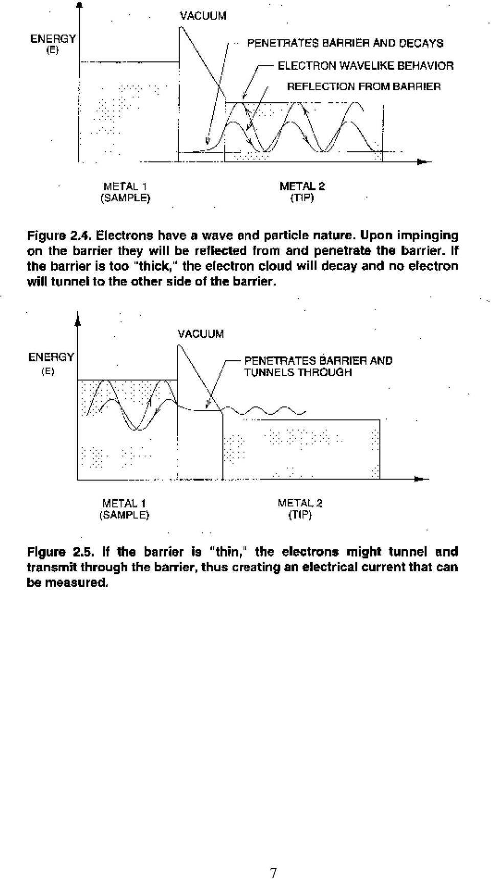
6 This picture shows that electrons are free to move around in their respective metals but cannot leave them. No electron in a metal has sufficient kinetic energy to go over the barrier. One of the basic tenets of quantum mechanics is that electrons have both a particle and a wave nature. So we should picture the electron not as a hard ball impinging on the barrier, but as a cloud. The size of the cloud is related to the wavelength of the electron (a few angstroms). When the cloud collides with the barrier, part of the cloud may penetrate it. For thick barriers, the cloud will be reflected like a hard particle (see Figure.4). For thin barriers, however, part of the cloud may penetrate the barriers and appear on the other side. This process is called tunneling because the electron does not have enough kinetic energy to travel over the barrier, but is able to exist on the other side (see Figure.5). It is as if the electron found a way to dig a tunnel through the barrier. 6
. For thin barriers, however, part of the cloud may penetrate the barriers and appear on the other side.")
7 7
8 In the scanning tunneling microscope, one of the metals is the sample being imaged (sample) and the other metal is the probe (tip). The sample is usually flatter than the probe, as shown in Figure.6. If the probe is sharpened into a tip it will most likely have one atom at the end. All of the tunneling electrons will pass through this atom. As we will discuss later, this feature leads to the atomic resolution capabilities of the microscope. 8

9 1.3. Ouantifying the Tunneling Process Using Schrödinger's equation of quantum mechanics, we can actually predict how tunneling current increases as separation between two metals decreases. However, the final results of your tunneling experiments can be understood without knowing quantum mechanics. This more complete description is not necessary for understanding how the STM works; it therefore may be thought of as supplemental. The Drude model of a metal states that the potential energy of a metal is given by the solid line in Figure.3. The energy of all the electrons in the metal is lower than the height of the wall. The difference in energy between the most energetic electron and the vacuum energy is called the workfunction and is denoted by the symbol Φ. The wave nature of an electron, illustrated in Figures.4 and.5, is critical to explaining tunneling. The movement and shape of the electron wave is governed by Schroedinger's equation, which might be thought of as the quantum mechanical analog of Newton's equation of motion, F = ma. In the STM, tunneling takes place between the tip and the sample. A complete description of the tunneling process requires a solution of the three-dimensional form of Schroedinger's equation, which has the general form: H Ψ= E Ψ (1.1) [ ] [ ] where [H] and [E] are the Hamiltonian and total energy operators. The operators are expressed as: ( r ) -ħ Ψ,t Ψ ( r,t) + U Ψ ( r,t) = iħ (1.) m t For our purpose it is sufficient to use a one-dimensional analysis, which for the Schroedinger equation above is given by: where the equation: ( xt) Ψ, -ħ Ψ ( xt, ) + U ( x) Ψ ( xt, ) = iħ (1.3) m t (, ) (- - ω ) ( -ω ) i kx t ikx t Ψ xt = Ae + Be (1.4) is the plane wave representation for an electron wavefunction of wavenumber k = π/λ and angular frequency ω. In addition, we assume a steady-state (time-independent) situation in which electrons of energy E(x, t) = E encountering a uniform potential barrier of height U(x, t) = U(x) are 9

10 continuously flowing from one metal to the other. It is then necessary to solve only the one-dimensional steady-state Schroedinger equation, given by: ħ m Ψ x ( x ) ( ) ( ) ( ) + U x Ψ x = EΨ x (1.5) where E is the kinetic energy of the electron. Note that U(x) is the potential energy of the electron as a function of position, as shown in Figure.3. U(x) is smaller than the electron energy in the metals and larger than the electron energy in the barrier. For simplicity we can assume U(x) = U 0 a constant in the barrier. In the metal, the general solution to the above equation is given by: (Metal 1) ( ) ( 0 ) m E U ikx + ikx Ψ x = Ae + Be, k = ħ (1.6) (Metal ) ( ) ikx + ikx Ψ x = Ee + Fe (1.7) and in the barrier (the classically forbidden region) the solution is: 10
 is smaller than the electron energy in the metals and larger than the electron energy in the barrier. For simplicity we can assume U(x) = U 0 a constant in the barrier.")
11 (barrier) ( ) ( 0 ) mu E µ x + µ x Ψ x = Ce + De, µ = ħ (1.8) Equations 1.6 and 1.7 show that the phase of the electron wavefunction varies uniformly in the metals. The wavelength is λ = 1/k. Higher energy electrons have a smaller wavelength. When a high energy electron wave encounters the boundary of the metal, it "leaks out" a small amount, as discussed in the previous section. The "intensity" of the electron wave decays as a function of distance from the boundary. Mathematically, the argument of the exponential function becomes real and the electron wavefunction decays. (For imaginary arguments, the wave function would have oscillatory behavior.) To gain a quantitative insight into the electron tunneling phenomena, it is necessary to derive an expression for the transmission coefficient, i.e. the transmitted flux from the sample to the tip through the barrier of width L. The barrier is considered wide but finite, such that the electron wavefunction exponential decay in the barrier is significant. Furthermore, the electron wavefunction and its first derivative must be continuous (join smoothly) at the sample-barrier and tip-barrier boundaries to conserve energy and mass. If we set up a coordinate system in which the surface of the sample (Metal 1) is at x = 0 and the tip (Metal ) is at x = L, and apply the boundary conditions for continuity: A+ B C ( ) ik A B µ C (1.9) (at the sample surface, x = 0) where D, the amplitude of the reflected wavefunction at the tip-barrier boundary, is neglected, since D << A, B, C. However, D is not insignificant at the tip-barrier boundary. At the tip-barrier boundary, x = L, continuity would require: (1.10) Ce + De = Fe µ L µ L ikl µ Ce + µ De = ikfe µ L µ L ikl 11

12 Solving for B/A at x = 0, by solving for C and substituting for it, we get: (1.11) B A ( 1 ikδ ) ( 1 ikδ ) + where δ is 1/µ, A is the amplitude of the electron wavefunction in the sample surface incident on the barrier, and B represents the amplitude of the reflected wavefunction. The reflection coefficient (R) for the wavefunction is then defined as: (1.1) R B A where represents the product of a complex number and its conjugate. In this case, it represents the relative intensities of the incident and reflected wavefunctions. An electron incident at the barrier will either be reflected or transmitted through the barrier. In terms of probability or frequency of occurrence, R+T = 1, where R and T are the reflection and transmission coefficients. Thus: (1.13) and, therefore: (1.14) ( 1 ikδ ) ( 1 ikδ ) B + R = 1 A T = 1 R 0 which indicates that, for an infinitely wide barrier, no electrons would be found in the barrier region. Nevertheless, dividing the first of the sample vacuum-barrier boundary conditions by A results in: (1.15) 1+ B C A A 1

13 The probability of finding an electron in the barrier region at x = 0, due to quantum tunneling, is given by: (1.16) C A ( kδ ) ( kδ ) F To find the effective tunneling transmission coefficient, i.e. the relative A probability or frequency of occurrence of an electron tunneling out of the sample surface, across the sample-tip-barrier region, and into the tip, combine the tip-barrier boundary equations (at x L) and Equation 1.16 to get: (1.17) F A 4ikδ ( 1 ikδ ) e ( µ ik ) L + which produces the desired quantitative result: (1.18) where: L 4kδ δ F T ( E) e e A ( 1+ ( kδ ) ) k me = ħ ( kδ ) EU ( E) E = 0 = Φ L mφ/ h (1.19) 13
 and Equation 1.16 to get: (1.")
14 Substituting typical numbers of -34 ħ = 1.05x10 joule-seconds, results in: T E -19 Φ= 5x10 joules, L ( ) e, L in Angstroms =. -31 m = 9.11x10 kilograms, and This formula shows that for each angstrom change in separation, the probability that an electron tunnels decreases by an order of magnitude. This demonstrates mathematically that tunneling current is indeed a sensitive measure of the distance between the tip and sample. In the STM, one of the metals is the sample being looked at and the other metal is the probe. The sample is usually flatter than the probe, as shown in Figure.6. Because the probe is formed of atoms, if it is sharpened into a tip, it will most likely have one atom at the end of the tip. The spacing between atoms is about 3 angstroms. Therefore, any tunneling through atoms that are one atom back from the closest atom is a fraction ( )( 3 ) e = 0.00 of tunneling through the atom at the tip, as shown in Figure.6. Virtually all of the tunneling electrons will pass through the single atom closest to the surface. This feature produces the atomic resolution capabilities of the microscope. 14

15 Holographic Gold Grating: STM Magnification Experiment To attain atomic resolution for gold, the STM signal has to be particularly low in noise. The very nature of the metal means that the electrons will be strongly delocalized between the atoms and there will only be small variations in the electron density with atomic position. The periodic modulations are typically on the order of 0.1 Å, so one should not expect to image gold atoms in normal room conditions. The purpose of this experiment is to introduce the concepts of tunneling and the extremely delocalized nature of electrons defined by the metallic state. The first sample to examine is the gold-coated holographic grating. This sample is a single-period hologram with a sinusoidal spacing of 0.4 µm (4000 Å). A hologram of the type seen on credit cards is composed of many such sinusoidal patterns of varying periods and orientations, which recreate the original image when viewing the diffracted or scattered light off the surface. This sample illustrates the piezoelectric tube scanner range and reinforces the level of magnification possible with the STM. The reference images are: grating1.img, grating.img grating3.img, grating4.img, and grating5.img. These are images of 400 lines/mm or about 0.4 µm (4000 Å) line spacing. Procedure: Head Preparation 1. Prepare either a PtIr or W tip and mount the tip.. Select the gold grating from the sample set and mount the sample. 3. Turn the Sample Position dial until the sample range indicator is close to the middle of the range or the sample-tip spacing is less than 0.5 mm. Be careful not to damage the tip and the sample. Software Preparation 4. Load grating3.img (File/Load). This image is shown in Figure 4.9. Set the Scan Delay (Configuration menu ) to 0. ms/sample. 5. In this scan you are monitoring height variations, so set the Data Type to Topographic (Configuration menu). 15

16 Electronics Preparation 6. Set the Bias Voltage to about 1 volt. 7. Set the Reference Current to 8 na. 8. Set the Servo Loop Response for constant current mode of operation. Set the Gain Close to maximum. Set the Filter close to maximum. Set the Time Constant to minimum. 9. Set the magnification to Xl. 10. Set the X and Y offset slides at their middle range. 11. Press the Tunneling Current button to monitor tunneling current (it should read about zero)

17 Tunneling 1. Press the Coarse Retract button momentarily to reset the motor controls. 13. Press the Auto Approach (Tunneling) button for approach and wait. 14. Monitor the tunneling current until it reaches about 8 na (equal to the reference Current). If the tunneling current oscillates, reduce the Gain and Filter or increase the Time Constant to stop the oscillation. 15. Once tunneling is achieved, start a unidirectional scan (Collect/ Scan Unidirectional). 16. Collect images and save one at this range. NOTE: Press C key on your keyboard to collect an image. Pressing C during a scan will capture the image at the end of the scan. Then you must use either Save or Save as command to save the image into the hard disk. To cancel image capture at the end of a scan, press C key again. 17. Change the scanner range by turning the magnification dial. Set the software size correctly in the menu by setting the Magnification knob (Configuration menu ). Collect an image at each setting. The large scan range should reveal a sinusoidal pattern on the surface with a period of 4167 Å and height variations of 1000 ± 100 Å, as shown in Figure As you zoom in, the details of the gold crystallization process on the hologram should become apparent. The evaporated gold tends to rapidly diffuse to form random crystallites with grain sizes of approximately 60 to 100 Å. You can prepare a montage of all the collected scans (from 8 the Windows display mode) to visualize an overall factor of magnification of 10 at the highest magnification (such as in the images grating1.img through grating4.img). 17
. 16. Collect images and save one at this range. NOTE: Press C key on your keyboard to collect an image.")
18 Only for extremely quiet tunneling conditions will it be possible to discern atomic features. The best chance of obtaining atomic features is from the constant height mode at high scan speeds. Set the tunneling current to 4 to 5 na and use a bias voltage of ~100 mv. You should compare this image to the constant height scans. The constant current mode cannot operate at as high a scan speed because it is limited by the response-time of the feedback loop; it is also more prone to acoustic noise than the constant height mode. The tip is extremely important in this regard, so you may want to try different tips. However, you should not expect to attain atomic resolution in this experiment. The main point here is to get an approximate determination of the maximum periodic variation in the electron density across the surface. 18

19 Load a representative image (File/Load). Use the cursor and draw a line through the data to visualize the fluctuations in tunneling current (Display/Cross Section). The current should be fairly constant across the surface, with variations of less than 0.1 Åin the tip position, to maintain constant current. The noise on your data may exceed this value, so you may want to filter the data-to reduce the noise level in the image. The main point is that the low degree of current variation across the surface illustrates the highly delocalized nature of electrons in metals. This study should be contrasted to that of graphite in the next section. Questions 1. Sometime during the use of the STM, the tip may have crashed. This is observable as a sudden large change in the current. This occurs when there is a change in the surface topology to which the feedback loop does not respond quickly enough and the tip touches the surface. Calculate the effective resistance of the tunneling gap for the conditions used in your experiment and compare that to the expected resistance if the tip was in direct ohmic contact with the surface. The resistivity of gold is 8 10 Ω /cm. This comparison should graphically illustrate the tunneling effect you are observing.. As the temperature of metals is raised, the resistance to current flow increases. Discuss the mechanism of resistance in metals and compare this mechanism to electron tunneling. How would the temperature dependence of the two mechanisms differ? 3. Because these experiments were conducted in air, adsorbed water, solvents, and gases are undoubtedly on the surface. How do these molecules affect the tunneling process and how might the tip perturb their distribution? Contaminants on the tip are also likely problems. Explain how this would affect the noise on your STM experiment. 4. Consider the problem of the electron source in these experiments. If the tip is not scanned but left stationary over the surface, at a fixed distance that corresponds to a tunneling current of 1 na, calculate the number of electrons/second that flow through the atoms that participate in the tunneling process between the gold and tip surfaces. 19

20 3 Imaging Graphite This lab should provide direct observation of atomic features of the graphite surface. It should also serve to contrast the difference in the spatial variation of electron density at the Fermi level between metals and semimetals. This reflects the nature of and the degree of overlap in the atomic orbitals involved. Procedure: Head Preparation 1. Prepare either a PtIr or W tip and mount the tip.. Select the HOPG (graphite) from the sample set and mount the sample. 3. Turn the Sample Position dial until the sample range indicator is close to the middle of the range or the sample-tip spacing is less than 0.5 mm. Be careful not to damage the tip and the sample. Make sure an optically flat portion of the sample is under the tip. Software Preparation 4. Load graph1.img (File/Load). 5. Set the Scan Delay (Configuration menu ) to 0.0 ms/sample. 6. In this scan you are monitoring current variations, so set the Data Type to Current (Configuration menu). 0
 from the sample set and mount the sample. 3.")
21 Electronics Preparation 7. Set the Bias Voltage to about -50 mv. 8. Set the Reference Current to na. 9. Set the Servo Loop Response for constant height mode of operation. Set the Gain close to minimum. Set the Filter close to minimum. Set the Time Constant to maximum. 10. Set the magnification to X Set the X and Y offset slides at their middle range. 1. Press the Tunneling Current button to monitor tunneling current (it should read about zero). Tunneling 13. Press the Coarse Retract button momentarily to reset the motor controls. 14. Press the Auto Approach (Tunneling) button for approach and wait. 15. Monitor the tunneling current until it reaches about na (equal to the reference current). Adjust the Gain, Time Constant, and Filter, if necessary, to stop any tunneling oscillation. 16. Once tunneling is achieved, start a unidirectional scan (Collect/ Scan Unidirectional). Scan over a few areas of the surface by using the X and Y slide bars to find a relatively flat region. The tip needs some conditioning to remove contaminants, so it may take a while for the tunneling current to settle. NOTE: You may have to use the X and Y slide to find flat areas on the sample. When using these slides note that the image on the screen moves accordingly. However, it may take a few minutes for the tip to settle and for the drifts to become small. Be careful when using the X and Y slides. The total range of the slides always corresponds to the maximum scanner size. Moving the slides for large distances and frequent times will distort images. This distortion is due to electromechanical properties of PZT. 17. Collect images and save one at this range. 1
22 NOTE: Press C key on your keyboard to collect an image. Pressing C during a scan will capture the image at the end of the scan. Then you must use either Save or Save as command to save the image into the hard disk. To cancel image capture at the end of a scan, press C key again. 18. Change the scanner range by adjusting the magnification dial. Set the software size correctly in the menu by setting the Magnification knob (Configuration menu). Collect an image at each setting. Acquire images with effective sizes of 1000 Å, 500 Å, 100 Å and 0 Å. 19. Attempt to acquire images in the constant current mode by setting the Gain close to maximum. Set the Filter close to maximum. Set the Time Constant to minimum. Set the scan delay (Configuration menu ) to 0.0 msec and collect topographic data. Usually the best images are obtained in the constant height mode. If the above procedures (steps 16-19) do not work, back off the tip and change tips. You should also cleave the surface again if repeated attempts don't bring out atomic details. It should be possible to obtain images of graphite like those shown in Figure If you get very stable graphite images, you should collect a number of scans, as a function of bias, to see how the appearance of the graphite lattice changes with bias. For a select scan, go into the display mode and use the cursor feature to determine the spatial variation in the constant current position of the tip. You may want to filter your data before you do this. Your data should show variations in surface topology of 1- Å. Variations may be larger in certain cases because of surface-tip interactions. Contrast this result to the earlier study of gold surfaces (Section.1.1). For most images it should be possible to determine the hexagonal surface structure bond angles and approximate bond lengths of graphite. You should keep in mind the α and β types of carbon atoms in making your assignments. Multiple tip effects may also be observable. From your lowest noise image, it is particularly interesting to look at the surface structure using the 3-Dimensional perspective view display mode.
23 A sample graphite image taken at X50 is shown below. The scan is 30 Å x 30 Å acquired in constant height mode. 3
Lecture 6 Scanning Tunneling Microscopy (STM) General components of STM; Tunneling current; Feedback system; Tip --- the probe.
 General components of STM; Tunneling current; Feedback system; Tip --- the probe.") Lecture 6 Scanning Tunneling Microscopy (STM) General components of STM; Tunneling current; Feedback system; Tip --- the probe. Brief Overview of STM Inventors of STM The Nobel Prize in Physics 1986 Nobel
Lecture 6 Scanning Tunneling Microscopy (STM) General components of STM; Tunneling current; Feedback system; Tip --- the probe. Brief Overview of STM Inventors of STM The Nobel Prize in Physics 1986 Nobel
- particle with kinetic energy E strikes a barrier with height U 0 > E and width L. - classically the particle cannot overcome the barrier
 Tunnel Effect: - particle with kinetic energy E strikes a barrier with height U 0 > E and width L - classically the particle cannot overcome the barrier - quantum mechanically the particle can penetrated
Lab 9: The Acousto-Optic Effect
 Lab 9: The Acousto-Optic Effect Incoming Laser Beam Travelling Acoustic Wave (longitudinal wave) O A 1st order diffracted laser beam A 1 Introduction qb d O 2qb rarefractions compressions Refer to Appendix
Waves: Recording Sound Waves and Sound Wave Interference (Teacher s Guide)
") Waves: Recording Sound Waves and Sound Wave Interference (Teacher s Guide) OVERVIEW Students will measure a sound wave by placing the Ward s DataHub microphone near one tuning fork A440 (f=440hz). Then
Waves: Recording Sound Waves and Sound Wave Interference (Teacher s Guide) OVERVIEW Students will measure a sound wave by placing the Ward s DataHub microphone near one tuning fork A440 (f=440hz). Then
Lecture 4 Scanning Probe Microscopy (SPM)
") Lecture 4 Scanning Probe Microscopy (SPM) General components of SPM; Tip --- the probe; Cantilever --- the indicator of the tip; Tip-sample interaction --- the feedback system; Scanner --- piezoelectric
Lecture 4 Scanning Probe Microscopy (SPM) General components of SPM; Tip --- the probe; Cantilever --- the indicator of the tip; Tip-sample interaction --- the feedback system; Scanner --- piezoelectric
NUCLEAR MAGNETIC RESONANCE. Advanced Laboratory, Physics 407, University of Wisconsin Madison, Wisconsin 53706
 (revised 4/21/03) NUCLEAR MAGNETIC RESONANCE Advanced Laboratory, Physics 407, University of Wisconsin Madison, Wisconsin 53706 Abstract This experiment studies the Nuclear Magnetic Resonance of protons
Acousto-optic modulator
 1 of 3 Acousto-optic modulator F An acousto-optic modulator (AOM), also called a Bragg cell, uses the acousto-optic effect to diffract and shift the frequency of light using sound waves (usually at radio-frequency).
PS-6.2 Explain the factors that determine potential and kinetic energy and the transformation of one to the other.
 PS-6.1 Explain how the law of conservation of energy applies to the transformation of various forms of energy (including mechanical energy, electrical energy, chemical energy, light energy, sound energy,
DIODE CIRCUITS LABORATORY. Fig. 8.1a Fig 8.1b
 DIODE CIRCUITS LABORATORY A solid state diode consists of a junction of either dissimilar semiconductors (pn junction diode) or a metal and a semiconductor (Schottky barrier diode). Regardless of the type,
FLAP P11.2 The quantum harmonic oscillator
 F L E X I B L E L E A R N I N G A P P R O A C H T O P H Y S I C S Module P. Opening items. Module introduction. Fast track questions.3 Ready to study? The harmonic oscillator. Classical description of
Chapter NP-5. Nuclear Physics. Nuclear Reactions TABLE OF CONTENTS INTRODUCTION OBJECTIVES 1.0 NUCLEAR REACTIONS 2.0 NEUTRON INTERACTIONS
 Chapter NP-5 Nuclear Physics Nuclear Reactions TABLE OF CONTENTS INTRODUCTION OBJECTIVES 1.0 2.0 NEUTRON INTERACTIONS 2.1 ELASTIC SCATTERING 2.2 INELASTIC SCATTERING 2.3 RADIATIVE CAPTURE 2.4 PARTICLE
Force on Moving Charges in a Magnetic Field
 [ Assignment View ] [ Eðlisfræði 2, vor 2007 27. Magnetic Field and Magnetic Forces Assignment is due at 2:00am on Wednesday, February 28, 2007 Credit for problems submitted late will decrease to 0% after
PHOTOELECTRIC EFFECT AND DUAL NATURE OF MATTER AND RADIATIONS
 PHOTOELECTRIC EFFECT AND DUAL NATURE OF MATTER AND RADIATIONS 1. Photons 2. Photoelectric Effect 3. Experimental Set-up to study Photoelectric Effect 4. Effect of Intensity, Frequency, Potential on P.E.
Vacuum Evaporation Recap
 Sputtering Vacuum Evaporation Recap Use high temperatures at high vacuum to evaporate (eject) atoms or molecules off a material surface. Use ballistic flow to transport them to a substrate and deposit.
Atomic Structure Ron Robertson
 Atomic Structure Ron Robertson r2 n:\files\courses\1110-20\2010 possible slides for web\atomicstructuretrans.doc I. What is Light? Debate in 1600's: Since waves or particles can transfer energy, what is
Free Electron Fermi Gas (Kittel Ch. 6)
") Free Electron Fermi Gas (Kittel Ch. 6) Role of Electrons in Solids Electrons are responsible for binding of crystals -- they are the glue that hold the nuclei together Types of binding (see next slide)
Free Electron Fermi Gas (Kittel Ch. 6) Role of Electrons in Solids Electrons are responsible for binding of crystals -- they are the glue that hold the nuclei together Types of binding (see next slide)
Lab 1: The Digital Oscilloscope
 PHYSICS 220 Physical Electronics Lab 1: The Digital Oscilloscope Object: To become familiar with the oscilloscope, a ubiquitous instrument for observing and measuring electronic signals. Apparatus: Tektronix
Blackbody Radiation References INTRODUCTION
 Blackbody Radiation References 1) R.A. Serway, R.J. Beichner: Physics for Scientists and Engineers with Modern Physics, 5 th Edition, Vol. 2, Ch.40, Saunders College Publishing (A Division of Harcourt
Heating & Cooling in Molecular Clouds
 Lecture 8: Cloud Stability Heating & Cooling in Molecular Clouds Balance of heating and cooling processes helps to set the temperature in the gas. This then sets the minimum internal pressure in a core
Study the following diagrams of the States of Matter. Label the names of the Changes of State between the different states.
 Describe the strength of attractive forces between particles. Describe the amount of space between particles. Can the particles in this state be compressed? Do the particles in this state have a definite
ElectroMagnetic Induction. AP Physics B
 ElectroMagnetic Induction AP Physics B What is E/M Induction? Electromagnetic Induction is the process of using magnetic fields to produce voltage, and in a complete circuit, a current. Michael Faraday
Introduction to acoustic imaging
 Introduction to acoustic imaging Contents 1 Propagation of acoustic waves 3 1.1 Wave types.......................................... 3 1.2 Mathematical formulation.................................. 4 1.3
Indiana's Academic Standards 2010 ICP Indiana's Academic Standards 2016 ICP. map) that describe the relationship acceleration, velocity and distance.
 that describe the relationship acceleration, velocity and distance.") .1.1 Measure the motion of objects to understand.1.1 Develop graphical, the relationships among distance, velocity and mathematical, and pictorial acceleration. Develop deeper understanding through representations
.1.1 Measure the motion of objects to understand.1.1 Develop graphical, the relationships among distance, velocity and mathematical, and pictorial acceleration. Develop deeper understanding through representations
Magnetic Field of a Circular Coil Lab 12
 HB 11-26-07 Magnetic Field of a Circular Coil Lab 12 1 Magnetic Field of a Circular Coil Lab 12 Equipment- coil apparatus, BK Precision 2120B oscilloscope, Fluke multimeter, Wavetek FG3C function generator,
AS COMPETITION PAPER 2008
 AS COMPETITION PAPER 28 Name School Town & County Total Mark/5 Time Allowed: One hour Attempt as many questions as you can. Write your answers on this question paper. Marks allocated for each question
PUMPED Nd:YAG LASER. Last Revision: August 21, 2007
 PUMPED Nd:YAG LASER Last Revision: August 21, 2007 QUESTION TO BE INVESTIGATED: How can an efficient atomic transition laser be constructed and characterized? INTRODUCTION: This lab exercise will allow
Does Quantum Mechanics Make Sense? Size
 Does Quantum Mechanics Make Sense? Some relatively simple concepts show why the answer is yes. Size Classical Mechanics Quantum Mechanics Relative Absolute What does relative vs. absolute size mean? Why
Physics 9e/Cutnell. correlated to the. College Board AP Physics 1 Course Objectives
 Physics 9e/Cutnell correlated to the College Board AP Physics 1 Course Objectives Big Idea 1: Objects and systems have properties such as mass and charge. Systems may have internal structure. Enduring
Electrical Resonance
 Electrical Resonance (R-L-C series circuit) APPARATUS 1. R-L-C Circuit board 2. Signal generator 3. Oscilloscope Tektronix TDS1002 with two sets of leads (see Introduction to the Oscilloscope ) INTRODUCTION
Assessment Plan for Learning Outcomes for BA/BS in Physics
 Department of Physics and Astronomy Goals and Learning Outcomes 1. Students know basic physics principles [BS, BA, MS] 1.1 Students can demonstrate an understanding of Newton s laws 1.2 Students can demonstrate
Electromagnetic Induction: Faraday's Law
 1 Electromagnetic Induction: Faraday's Law OBJECTIVE: To understand how changing magnetic fields can produce electric currents. To examine Lenz's Law and the derivative form of Faraday's Law. EQUIPMENT:
Experiment #4, Ohmic Heat
 Experiment #4, Ohmic Heat 1 Purpose Physics 18 - Fall 013 - Experiment #4 1 1. To demonstrate the conversion of the electric energy into heat.. To demonstrate that the rate of heat generation in an electrical
Figure 1. Diode circuit model
 Semiconductor Devices Non-linear Devices Diodes Introduction. The diode is two terminal non linear device whose I-V characteristic besides exhibiting non-linear behavior is also polarity dependent. The
Sample Questions for the AP Physics 1 Exam
 Sample Questions for the AP Physics 1 Exam Sample Questions for the AP Physics 1 Exam Multiple-choice Questions Note: To simplify calculations, you may use g 5 10 m/s 2 in all problems. Directions: Each
Using light scattering method to find The surface tension of water
 Experiment (8) Using light scattering method to find The surface tension of water The aim of work: The goals of this experiment are to confirm the relationship between angular frequency and wave vector
v = fλ PROGRESSIVE WAVES 1 Candidates should be able to :
 PROGRESSIVE WAVES 1 Candidates should be able to : Describe and distinguish between progressive longitudinal and transverse waves. With the exception of electromagnetic waves, which do not need a material
Chapter 6 Work and Energy
 Chapter 6 WORK AND ENERGY PREVIEW Work is the scalar product of the force acting on an object and the displacement through which it acts. When work is done on or by a system, the energy of that system
............... [2] At the time of purchase of a Strontium-90 source, the activity is 3.7 10 6 Bq.
![............... [2] At the time of purchase of a Strontium-90 source, the activity is 3.7 10 6 Bq.](/thumbs/40/21837699.jpg "............... [2] At the time of purchase of a Strontium-90 source, the activity is 3.7 10 6 Bq.") 1 Strontium-90 decays with the emission of a β-particle to form Yttrium-90. The reaction is represented by the equation 90 38 The decay constant is 0.025 year 1. 90 39 0 1 Sr Y + e + 0.55 MeV. (a) Suggest,
1 Strontium-90 decays with the emission of a β-particle to form Yttrium-90. The reaction is represented by the equation 90 38 The decay constant is 0.025 year 1. 90 39 0 1 Sr Y + e + 0.55 MeV. (a) Suggest,
ELECTRON SPIN RESONANCE Last Revised: July 2007
 QUESTION TO BE INVESTIGATED ELECTRON SPIN RESONANCE Last Revised: July 2007 How can we measure the Landé g factor for the free electron in DPPH as predicted by quantum mechanics? INTRODUCTION Electron
Physics 441/2: Transmission Electron Microscope
 Physics 441/2: Transmission Electron Microscope Introduction In this experiment we will explore the use of transmission electron microscopy (TEM) to take us into the world of ultrasmall structures. This
LAB 6 - GRAVITATIONAL AND PASSIVE FORCES
 L06-1 Name Date Partners LAB 6 - GRAVITATIONAL AND PASSIVE FORCES OBJECTIVES And thus Nature will be very conformable to herself and very simple, performing all the great Motions of the heavenly Bodies
Lab Exercise 1: Acoustic Waves
 Lab Exercise 1: Acoustic Waves Contents 1-1 PRE-LAB ASSIGNMENT................. 2 1-3.1 Spreading Factor: Spherical Waves........ 2 1-3.2 Interference In 3-D................. 3 1-4 EQUIPMENT........................
Ultrasonic Wave Propagation Review
 Ultrasonic Wave Propagation Review Presented by: Sami El-Ali 1 1. Introduction Ultrasonic refers to any study or application of sound waves that are higher frequency than the human audible range. Ultrasonic
Appendix A: Science Practices for AP Physics 1 and 2
 Appendix A: Science Practices for AP Physics 1 and 2 Science Practice 1: The student can use representations and models to communicate scientific phenomena and solve scientific problems. The real world
UNIT I: INTRFERENCE & DIFFRACTION Div. B Div. D Div. F INTRFERENCE
 107002: EngineeringPhysics Teaching Scheme: Lectures: 4 Hrs/week Practicals-2 Hrs./week T.W.-25 marks Examination Scheme: Paper-50 marks (2 hrs) Online -50marks Prerequisite: Basics till 12 th Standard
Stability of Evaporating Polymer Films. For: Dr. Roger Bonnecaze Surface Phenomena (ChE 385M)
") Stability of Evaporating Polymer Films For: Dr. Roger Bonnecaze Surface Phenomena (ChE 385M) Submitted by: Ted Moore 4 May 2000 Motivation This problem was selected because the writer observed a dependence
Stability of Evaporating Polymer Films For: Dr. Roger Bonnecaze Surface Phenomena (ChE 385M) Submitted by: Ted Moore 4 May 2000 Motivation This problem was selected because the writer observed a dependence
Positive Feedback and Oscillators
 Physics 3330 Experiment #6 Fall 1999 Positive Feedback and Oscillators Purpose In this experiment we will study how spontaneous oscillations may be caused by positive feedback. You will construct an active
INTERFERENCE OF SOUND WAVES
 1/2016 Sound 1/8 INTERFERENCE OF SOUND WAVES PURPOSE: To measure the wavelength, frequency, and propagation speed of ultrasonic sound waves and to observe interference phenomena with ultrasonic sound waves.
The rate of change of velocity with respect to time. The average rate of change of distance/displacement with respect to time.
 H2 PHYSICS DEFINITIONS LIST Scalar Vector Term Displacement, s Speed Velocity, v Acceleration, a Average speed/velocity Instantaneous Velocity Newton s First Law Newton s Second Law Newton s Third Law
E/M Experiment: Electrons in a Magnetic Field.
 E/M Experiment: Electrons in a Magnetic Field. PRE-LAB You will be doing this experiment before we cover the relevant material in class. But there are only two fundamental concepts that you need to understand.
DO PHYSICS ONLINE FROM QUANTA TO QUARKS QUANTUM (WAVE) MECHANICS
 MECHANICS") DO PHYSICS ONLINE FROM QUANTA TO QUARKS QUANTUM (WAVE) MECHANICS Quantum Mechanics or wave mechanics is the best mathematical theory used today to describe and predict the behaviour of particles and waves.
DO PHYSICS ONLINE FROM QUANTA TO QUARKS QUANTUM (WAVE) MECHANICS Quantum Mechanics or wave mechanics is the best mathematical theory used today to describe and predict the behaviour of particles and waves.
Chapter 18: The Structure of the Atom
 Chapter 18: The Structure of the Atom 1. For most elements, an atom has A. no neutrons in the nucleus. B. more protons than electrons. C. less neutrons than electrons. D. just as many electrons as protons.
SAM Teachers Guide Heat and Temperature
 SAM Teachers Guide Heat and Temperature Overview Students learn that temperature measures average kinetic energy, and heat is the transfer of energy from hot systems to cold systems. They consider what
ELECTRIC FIELD LINES AND EQUIPOTENTIAL SURFACES
 ELECTRIC FIELD LINES AND EQUIPOTENTIAL SURFACES The purpose of this lab session is to experimentally investigate the relation between electric field lines of force and equipotential surfaces in two dimensions.
Monday 11 June 2012 Afternoon
 Monday 11 June 2012 Afternoon A2 GCE PHYSICS B (ADVANCING PHYSICS) G495 Field and Particle Pictures *G412090612* Candidates answer on the Question Paper. OCR supplied materials: Data, Formulae and Relationships
Name Partners Date. Energy Diagrams I
 Name Partners Date Visual Quantum Mechanics The Next Generation Energy Diagrams I Goal Changes in energy are a good way to describe an object s motion. Here you will construct energy diagrams for a toy
TEACHER S CLUB EXAMS GRADE 11. PHYSICAL SCIENCES: PHYSICS Paper 1
 TEACHER S CLUB EXAMS GRADE 11 PHYSICAL SCIENCES: PHYSICS Paper 1 MARKS: 150 TIME: 3 hours INSTRUCTIONS AND INFORMATION 1. This question paper consists of 12 pages, two data sheets and a sheet of graph
Experiment 1: SOUND. The equation used to describe a simple sinusoidal function that propagates in space is given by Y = A o sin(k(x v t))
)") Experiment 1: SOUND Introduction Sound is classified under the topic of mechanical waves. A mechanical wave is a term which refers to a displacement of elements in a medium from their equilibrium state,
Experiment 1: SOUND Introduction Sound is classified under the topic of mechanical waves. A mechanical wave is a term which refers to a displacement of elements in a medium from their equilibrium state,
A More Efficient Way to De-shelve 137 Ba +
 A More Efficient Way to De-shelve 137 Ba + Abstract: Andrea Katz Trinity University UW REU 2010 In order to increase the efficiency and reliability of de-shelving barium ions, an infrared laser beam was
Untitled Document. 1. Which of the following best describes an atom? 4. Which statement best describes the density of an atom s nucleus?
 Name: Date: 1. Which of the following best describes an atom? A. protons and electrons grouped together in a random pattern B. protons and electrons grouped together in an alternating pattern C. a core
Introduction OLEDs OTFTs OPVC Summary. Organic Electronics. Felix Buth. Walter Schottky Institut, TU München. Joint Advanced Student School 2008
 Felix Buth Joint Advanced Student School 2008 Outline 1 Introduction Difference organic/inorganic semiconductors From molecular orbitals to the molecular crystal 2 Organic Light Emitting Diodes Basic Principals
Atomic Force Microscope and Magnetic Force Microscope Background Information
 Atomic Force Microscope and Magnetic Force Microscope Background Information Lego Building Instructions There are several places to find the building instructions for building the Lego models of atomic
Determination of Acceleration due to Gravity
 Experiment 2 24 Kuwait University Physics 105 Physics Department Determination of Acceleration due to Gravity Introduction In this experiment the acceleration due to gravity (g) is determined using two
5. Measurement of a magnetic field
 H 5. Measurement of a magnetic field 5.1 Introduction Magnetic fields play an important role in physics and engineering. In this experiment, three different methods are examined for the measurement of
Main properties of atoms and nucleus
 Main properties of atoms and nucleus. Atom Structure.... Structure of Nuclei... 3. Definition of Isotopes... 4. Energy Characteristics of Nuclei... 5. Laws of Radioactive Nuclei Transformation... 3. Atom
Laboratory #3 Guide: Optical and Electrical Properties of Transparent Conductors -- September 23, 2014
 Laboratory #3 Guide: Optical and Electrical Properties of Transparent Conductors -- September 23, 2014 Introduction Following our previous lab exercises, you now have the skills and understanding to control
Energy Transport. Focus on heat transfer. Heat Transfer Mechanisms: Conduction Radiation Convection (mass movement of fluids)
") Energy Transport Focus on heat transfer Heat Transfer Mechanisms: Conduction Radiation Convection (mass movement of fluids) Conduction Conduction heat transfer occurs only when there is physical contact
Energy Transport Focus on heat transfer Heat Transfer Mechanisms: Conduction Radiation Convection (mass movement of fluids) Conduction Conduction heat transfer occurs only when there is physical contact
Infrared Spectroscopy: Theory
 u Chapter 15 Infrared Spectroscopy: Theory An important tool of the organic chemist is Infrared Spectroscopy, or IR. IR spectra are acquired on a special instrument, called an IR spectrometer. IR is used
Science Standard Articulated by Grade Level Strand 5: Physical Science
 Concept 1: Properties of Objects and Materials Classify objects and materials by their observable properties. Kindergarten Grade 1 Grade 2 Grade 3 Grade 4 PO 1. Identify the following observable properties
Fraunhofer Diffraction
 Physics 334 Spring 1 Purpose Fraunhofer Diffraction The experiment will test the theory of Fraunhofer diffraction at a single slit by comparing a careful measurement of the angular dependence of intensity
Energy and Energy Transformations Test Review
 Energy and Energy Transformations Test Review Completion: 1. Mass 13. Kinetic 2. Four 14. thermal 3. Kinetic 15. Thermal energy (heat) 4. Electromagnetic/Radiant 16. Thermal energy (heat) 5. Thermal 17.
THERMAL RADIATION (THERM)
") UNIVERSITY OF SURREY DEPARTMENT OF PHYSICS Level 2 Classical Laboratory Experiment THERMAL RADIATION (THERM) Objectives In this experiment you will explore the basic characteristics of thermal radiation,
UNIVERSITY OF SURREY DEPARTMENT OF PHYSICS Level 2 Classical Laboratory Experiment THERMAL RADIATION (THERM) Objectives In this experiment you will explore the basic characteristics of thermal radiation,
Cambridge International Examinations Cambridge International General Certificate of Secondary Education
 Cambridge International Examinations Cambridge International General Certificate of Secondary Education *0123456789* PHYSICS 0625/04 Paper 4 Theory (Extended) For Examination from 2016 SPECIMEN PAPER 1
A-level PHYSICS (7408/1)
") SPECIMEN MATERIAL A-level PHYSICS (7408/1) Paper 1 Specimen 2014 Morning Time allowed: 2 hours Materials For this paper you must have: a pencil a ruler a calculator a data and formulae booklet. Instructions
SPECIMEN MATERIAL A-level PHYSICS (7408/1) Paper 1 Specimen 2014 Morning Time allowed: 2 hours Materials For this paper you must have: a pencil a ruler a calculator a data and formulae booklet. Instructions
Name Date Class STATES OF MATTER. SECTION 13.1 THE NATURE OF GASES (pages 385 389)
") 13 STATES OF MATTER SECTION 13.1 THE NATURE OF GASES (pages 385 389) This section introduces the kinetic theory and describes how it applies to gases. It defines gas pressure and explains how temperature
13 STATES OF MATTER SECTION 13.1 THE NATURE OF GASES (pages 385 389) This section introduces the kinetic theory and describes how it applies to gases. It defines gas pressure and explains how temperature
Optical Fibres. Introduction. Safety precautions. For your safety. For the safety of the apparatus
 Please do not remove this manual from from the lab. It is available at www.cm.ph.bham.ac.uk/y2lab Optics Introduction Optical fibres are widely used for transmitting data at high speeds. In this experiment,
Power Electronics. Prof. K. Gopakumar. Centre for Electronics Design and Technology. Indian Institute of Science, Bangalore.
 Power Electronics Prof. K. Gopakumar Centre for Electronics Design and Technology Indian Institute of Science, Bangalore Lecture - 1 Electric Drive Today, we will start with the topic on industrial drive
Soil Suction. Total Suction
 Soil Suction Total Suction Total soil suction is defined in terms of the free energy or the relative vapor pressure (relative humidity) of the soil moisture. Ψ = v RT ln v w 0ω v u v 0 ( u ) u = partial
Fall 2004 Ali Shakouri
 University of California at Santa Cruz Jack Baskin School of Engineering Electrical Engineering Department EE-145L: Properties of Materials Laboratory Lab 5b: Temperature Dependence of Semiconductor Conductivity
Development of Optical Wave Microphone Measuring Sound Waves with No Diaphragm
 Progress In Electromagnetics Research Symposium Proceedings, Taipei, March 5 8, 3 359 Development of Optical Wave Microphone Measuring Sound Waves with No Diaphragm Yoshito Sonoda, Takashi Samatsu, and
Sound absorption and acoustic surface impedance
 Sound absorption and acoustic surface impedance CHRISTER HEED SD2165 Stockholm October 2008 Marcus Wallenberg Laboratoriet för Ljud- och Vibrationsforskning Sound absorption and acoustic surface impedance
3. Diodes and Diode Circuits. 3. Diodes and Diode Circuits TLT-8016 Basic Analog Circuits 2005/2006 1
 3. Diodes and Diode Circuits 3. Diodes and Diode Circuits TLT-8016 Basic Analog Circuits 2005/2006 1 3.1 Diode Characteristics Small-Signal Diodes Diode: a semiconductor device, which conduct the current
CLASS TEST GRADE 11. PHYSICAL SCIENCES: PHYSICS Test 3: Electricity and magnetism
 CLASS TEST GRADE 11 PHYSICAL SCIENCES: PHYSICS Test 3: Electricity and magnetism MARKS: 45 TIME: 1 hour INSTRUCTIONS AND INFORMATION 1. Answer ALL the questions. 2. You may use non-programmable calculators.
Sound and stringed instruments
 Sound and stringed instruments Lecture 14: Sound and strings Reminders/Updates: HW 6 due Monday, 10pm. Exam 2, a week today! 1 Sound so far: Sound is a pressure or density fluctuation carried (usually)
LAB 6: GRAVITATIONAL AND PASSIVE FORCES
 55 Name Date Partners LAB 6: GRAVITATIONAL AND PASSIVE FORCES And thus Nature will be very conformable to herself and very simple, performing all the great Motions of the heavenly Bodies by the attraction
Calibration and Use of a Strain-Gage-Instrumented Beam: Density Determination and Weight-Flow-Rate Measurement
 Chapter 2 Calibration and Use of a Strain-Gage-Instrumented Beam: Density Determination and Weight-Flow-Rate Measurement 2.1 Introduction and Objectives This laboratory exercise involves the static calibration
Quantum Mechanics: Postulates
 Quantum Mechanics: Postulates 5th April 2010 I. Physical meaning of the Wavefunction Postulate 1: The wavefunction attempts to describe a quantum mechanical entity (photon, electron, x-ray, etc.) through
Active Vibration Isolation of an Unbalanced Machine Spindle
 UCRL-CONF-206108 Active Vibration Isolation of an Unbalanced Machine Spindle D. J. Hopkins, P. Geraghty August 18, 2004 American Society of Precision Engineering Annual Conference Orlando, FL, United States
Radioactivity III: Measurement of Half Life.
 PHY 192 Half Life 1 Radioactivity III: Measurement of Half Life. Introduction This experiment will once again use the apparatus of the first experiment, this time to measure radiation intensity as a function
Introduction to Netlogo: A Newton s Law of Gravity Simulation
 Introduction to Netlogo: A Newton s Law of Gravity Simulation Purpose Netlogo is an agent-based programming language that provides an all-inclusive platform for writing code, having graphics, and leaving
Physics 41, Winter 1998 Lab 1 - The Current Balance. Theory
 Physics 41, Winter 1998 Lab 1 - The Current Balance Theory Consider a point at a perpendicular distance d from a long straight wire carrying a current I as shown in figure 1. If the wire is very long compared
Electric Field Mapping Lab 3. Precautions
 HB 09-25-07 Electric Field Mapping Lab 3 1 Electric Field Mapping Lab 3 Equipment mapping board, U-probe, resistive boards, templates, dc voltmeter (431B), 4 long leads, 16 V dc for wall strip Reading
Crystal Optics of Visible Light
 Crystal Optics of Visible Light This can be a very helpful aspect of minerals in understanding the petrographic history of a rock. The manner by which light is transferred through a mineral is a means
Basics of Nuclear Physics and Fission
 Basics of Nuclear Physics and Fission A basic background in nuclear physics for those who want to start at the beginning. Some of the terms used in this factsheet can be found in IEER s on-line glossary.
Frequency Response of Filters
 School of Engineering Department of Electrical and Computer Engineering 332:224 Principles of Electrical Engineering II Laboratory Experiment 2 Frequency Response of Filters 1 Introduction Objectives To
AP1 Waves. (A) frequency (B) wavelength (C) speed (D) intensity. Answer: (A) and (D) frequency and intensity.
 frequency (B) wavelength (C) speed (D) intensity. Answer: (A) and (D) frequency and intensity.") 1. A fire truck is moving at a fairly high speed, with its siren emitting sound at a specific pitch. As the fire truck recedes from you which of the following characteristics of the sound wave from the
1. A fire truck is moving at a fairly high speed, with its siren emitting sound at a specific pitch. As the fire truck recedes from you which of the following characteristics of the sound wave from the
1. The Kinetic Theory of Matter states that all matter is composed of atoms and molecules that are in a constant state of constant random motion
 Physical Science Period: Name: ANSWER KEY Date: Practice Test for Unit 3: Ch. 3, and some of 15 and 16: Kinetic Theory of Matter, States of matter, and and thermodynamics, and gas laws. 1. The Kinetic
TOF FUNDAMENTALS TUTORIAL
 TOF FUNDAMENTALS TUTORIAL Presented By: JORDAN TOF PRODUCTS, INC. 990 Golden Gate Terrace Grass Valley, CA 95945 530-272-4580 / 530-272-2955 [fax] www.rmjordan.com [web] [email protected] [e-mail] This
Introduction to Fourier Transform Infrared Spectrometry
 Introduction to Fourier Transform Infrared Spectrometry What is FT-IR? I N T R O D U C T I O N FT-IR stands for Fourier Transform InfraRed, the preferred method of infrared spectroscopy. In infrared spectroscopy,
Introduction to microstructure
 Introduction to microstructure 1.1 What is microstructure? When describing the structure of a material, we make a clear distinction between its crystal structure and its microstructure. The term crystal