590 DRV Digital DC Drive Product Manual. Version 3 Software
|
|
|
- Tobias York
- 9 years ago
- Views:
Transcription
1 590 DRV Digital DC Drive Product Manual Version 3 Software Copyright Eurotherm Drives, Inc All rights strictly reserved. No part of this document may be stored in a retrieval system or transmitted in any form. Although every effort has been taken to ensure the accuracy of this manual, it may be necessary, without notice, to make amendments or correct omissions in this document. Eurotherm Drives, Inc. cannot accept responsibility for damage, injury, or expenses resulting therefrom. Procedures detailed in this manual are designed to be performed by personnel with sufficient training and/or experience. Only sufficiently qualified personnel familiar with the construction and operation of industrial drive equipment and the dangers of working with high-voltage electrical systems should attempt installation, adjustment, operation, or service of this equipment. Failure to follow these guidelines could result in damage to the equipment and severe injury or loss of life to personnel. If you are unsure of your qualifications or do not understand certain procedures in this manual, contact Eurotherm Drives Customer Service for assistance. Before attempting any procedures in this manual, including installation, verify that the model numbers on the product and in this manual match. If any discrepancy is found, contact Customer Service immediately. Procedures in this manual may contain Warnings, Cautions, and Notes. A Warning gives the reader information which, if disregarded, could cause injury or death. A Caution provides the reader with advice which, if disregarded, could cause damage to the equipment. A Note furnishes additional information for added emphasis or clarity. Printed in the United States of America HA Issue 3

2
3 Safety Warnings Safety Procedures in this manual may contain Warnings, Cautions, and Notes. A Warning gives the reader information which, if disregarded, could cause injury or death. A Caution provides the reader with advice which, if disregarded, could cause damage to the equipment. A Note furnishes additional information for added emphasis or clarity. The customer is responsible for assessing his or her ability to carry out the procedures in this manual. Make sure you understand a procedure and the precautions necessary to carry it out safely before beginning. If you are unsure of your ability to perform a function, or have questions about the procedures listed in this manual, contact Eurotherm Drives Customer Service at (704) WARNING! Only qualified personnel who thoroughly understand the operation of this equipment and any associated machinery should install, start-up, or attempt maintenance of this equipment. WARNING! This equipment uses hazardous voltages during operation. Never work on it or any other control equipment or motors without first removing all power supplies. Caution This equipment contains ESD (Electrostatic Discharge) sensitive parts. Observe static control precautions when handling, installing, and servicing this device. Caution This equipment was tested before it left our factory. However, before installation and start up, inspect all equipment for transit damage, loose parts, packing materials, etc. Caution Ruptured semiconductor devices may release toxic materials. Contact Eurotherm Drives or the semiconductor manufacturer for proper disposal procedures for semiconductors or other material. NOTE. The installation of this equipment must comply with all applicable national and local electrical codes. iii

4 Terms & Conditions EUROTHERM DRIVES INCORPORATED - TERMS AND CONDITIONS (ABRIDGED) The following text will in no way alter or void the contents of the Eurotherm Drives, Inc. - Terms and Conditions of Sale. It is only intended to clarify the responsibilities of each party. Delivery, Title and Risk... DELIVERY TO COMMON CARRIER OR POSTAL AUTHORITIES AT RESTON, VIRGINIA SHALL CONSTITUTE DELIVERY AND PASSING OF TITLE TO THE CUSTOMER, WHO SHALL THEREAFTER BE RESPONSIBLE FOR DELAYS, LOSS OR DAMAGE IN TRANSIT. Warranty and Liability A. Warranty of equipment found within 12 months after delivery thereof to be defective by reason of faulty materials, workmanship, or design. (i) The Customer will: (a) notify Eurotherm Drives, Inc. within four weeks of the defect becoming apparent (b) return the equipment forthwith, freight paid, to the premises of Eurotherm Drives, Inc. or (c) at the option of Eurotherm Drives, Inc. make the equipment available at the Customer s premises for attention by Eurotherm Drives, Inc. personnel. Where the equipment is repaired on the Customer s premises, the Customer accepts liability for the payment of travel and subsistence expenses of Eurotherm Drives, Inc. personnel. (ii) Eurotherm Drives, Inc. will: (a) repair or (at its option) replace any equipment manufactured by Eurotherm Drives, Inc. (b) for goods not manufactured by Eurotherm Drives, Inc., convey to the Customer only the benefits it may recover under any guarantee the manufacturer gives to Eurotherm Drives, Inc. B. Eurotherm Drives, Inc. accepts no liability under this clause: (i) for damage sustained in transit, (liability for which is dealt with in paragraph 8 hereof); (ii) for defects caused (a) by not following the instructions supplied with the equipment during installation, operation or maintenance or (b) by wear and tear, accident or misuse, improper operation or neglect or (c) by fitting any equipment which does not comply with Eurotherm Drives, Inc. recommendations or (d) otherwise as a result of failure of the Customer to comply in full with any manual or handbook containing the technical specifications and operating instructions supplied by Eurotherm Drives, Inc. with the equipment; (iii) where equipment has been used for an application other than that specified at the time the Order was acknowledged or not in accordance with Eurotherm Drives, Inc. instructions; (iv) where the Customer has failed to observe the terms of payment for the equipment and all other obligations imposed by these terms and conditions. C. Where equipment has been ordered, obtained or manufactured to the Customer s own design or specification, Eurotherm Drives, Inc. can accept no liability for any failure or defect in such equipment except insofar as such failure or defect arises directly as a result of the failure of Eurotherm Drives, Inc. to follow the design or specification provided. Eurotherm Drives, Inc. gives no warranty as to the fitness for any particular purpose of goods supplied to the Customer s design or specification. The Customer shall indemnify Eurotherm Drives, Inc. in respect of all liability, loss or damage suffered by Eurotherm Drives, Inc. as a result of Eurotherm Drives, Inc. following designs or specifications provided by the Customer including any such liability suffered as a result of a claim by a third party for infringement of intellectual property rights. D. Except as specifically set out herein, Eurotherm Drives, Inc. shall be under no liability in respect of the quality, conditions or description of equipment or for any loss or damage howsoever caused to the Customer or to any other person and any term, condition or representation to the contrary whether express or implied by statute, common law or otherwise is hereby expressly excluded. E. NO IMPLIED STATUTORY WARRANTY OR MERCHANTABILITY OR FITNESS FOR A PARTICULAR PURPOSE SHALL APPLY. iv

5 590 DRV DIGITAL DC DRIVE PRODUCT MANUAL Contents (Continued) Safety Eurotherm Drives Incorporated - Terms and Conditions (abridged) Chapter 1 Chapter 2 Chapter 3 Chapter 4 INTRODUCTION Scope Overview of the 590 DRV Digital Drive Standard Features Main Features Other Features Unpacking & Special Handling IDENTIFICATION Component Identification Labeling Nameplate Label Fuse Replacement Label Terminal Tightening Torque Label Connector Kit Label Labeling on High Horsepower Models INSTALLATION AND WIRING Recommended Tools Ventilation and Cooling Requirements Mounting Instructions Wiring Procedures Mounting 7.5 through 100 HP Units Power Wiring Control Wiring Speed Feedback Hardware Settings Drive Calibration Control Transformer Final Inspections START UP AND ADJUSTMENT Recommended Tools Check Motor Initial Drive Start Check Supply Adjust Current Loop (AUTOTUNE) Armature Current Waveform Check Motor Rotation Check Speed Feedback Calibration Cont. 1

6 590 DRV DIGITAL DC DRIVE PRODUCT MANUAL Contents (Continued) Chapter 4 Chapter 5 Chapter 6 START UP AND ADJUSTMENT (Continued) Setup for Field Weakening Adjust Speed Loop Other Parameters Recording Parameters Password Protection Entering a Password Changing a Password Button Reset TROUBLESHOOTING Initial Troubleshooting Procedure Recommended Tools Status LED Troubleshooting LED Functions Health, Alarm Messages and the Trip Reset Symbolic Error Messages Alarm Process Alarm Status Drive Diagnostics Hardware Troubleshooting Control Power Missing Field Fail Procedure Contractor Failed Procedure SCR Troubleshooting Motor Checks Configuration Errors and General Troubleshooting Common Performance Problems Parameter Toggles Between Two Conditions No SPEED DEMAND SPEED SETPOINT has an Unwanted Offset Signal Does Not Get Through the RAMP Test Points Contacting Customer Service SERVICE AND MAINTENANCE Service Procedures Preventive Maintenance Removing Lower Cover Changing the Controller Door Replacing the Controller Removing the Power Supply Board Replacing SCRs Cont. 2

7 590 DRV DIGITAL DC DRIVE PRODUCT MANUAL Contents (Continued) Appendix A TECHNICAL DESCRIPTION Control Circuits... App. A - 1 Power Circuits... App. A - 1 Overview of Features... App. A - 1 Specifications... App. A - 2 Storage and Operating Environment... App. A - 2 Electrical Ratings (590 Single-board power supply: AH385851U002/U003)... App. A - 3 Electrical Ratings (Three-board power supply: AH385128U004/U104)... App. A - 3 DC Supply Loading... App. A Controller Output Ratings... App. A - 4 Power Loss... App. A - 4 Mechanical Ratings... App. A - 4 Hardware Block Diagram... App. A Software Block Diagram... App. A - 4 RS422 Communications... App. A - 5 RS232 Communications... App. A - 5 Terminal Listing... App. A - 6 Terminal Specifications... App. A - 7 Analog Input and Output Terminals... App. A - 7 Digital Input Terminals... App. A - 7 Digital Output Terminals... App. A - 7 Terminal Descriptions... App. A - 8 Feedback Option Cards... App. A - 11 Switchable Tachometer Feedback card (AH385870U001)... App. A (Plastic Fiber Optic) Microtach Receiver Card (AH058654U001)... App. A Installation Information... App. A (Glass Fiber Optic) Microtach Receiver Card (AH386025U001)... App. A - 14 Wire-ended Encoder Receiver Card (AH387775Uxxx)... App. A - 16 Appendix B USING THE MAN MACHINE INTERFACE Definition & Scope... App. B - 1 Using the MMI... App. B - 1 Access and Adjustment... App. B - 1 Operation... App. B - 1 Software Overview... App. B - 1 MMI Menu Structure... App. B - 2 Default Settings... App. B - 2 Appendix C SETUP PARAMETERS RAMPS... App. C - 2 AUX I/O... App. C - 6 JOG/SLACK... App. C - 8 RAISE/LOWER... App. C - 10 Cont. 3

8 590 DRV DIGITAL DC DRIVE PRODUCT MANUAL Contents (Continued) Appendix C SETUP PARAMETERS (Continued) FIELD CONTROL... App. C - 12 CURRENT PROFILE... App. C - 18 STOP RATES... App. C -20 SETPOINT SUM 1... App. C -26 STANDSTILL... App. C -28 SPEED LOOP... App. C -30 SPEED LOOP::ADVANCED... App. C -32 SPEED LOOP::SETPOINTS... App. C -34 CURRENT LOOP... App. C -36 INHIBIT ALARMS... App. C -38 CALIBRATION... App. C -40 Appendix D I/O CONFIGURATION - SYSTEM MENU Appendix E INTRODUCTION... App. D - 1 MMI Access to CONFIGURE I/O... App. D - 1 Parameter types... App. D - 1 Configuration procedure... App. D - 2 ANALOG INPUTS... App. D - 3 Analog Inputs - Examples... App. D - 5 ANALOG OUTPUTS... App. D - 7 Analog Outputs - Examples... App. D - 9 DIGITAL INPUTS... App. D - 11 Digital Inputs - Examples... App. D - 13 DIGITAL OUTPUTS... App. D - 15 Digital Outputs - Examples... App. D - 17 CONFIGURE App. D - 18 BLOCK DIAGRAM... App. D - 19 INTERNAL LINKS... App. D - 21 Internal Links - Example... App. D -23 MMI PARAMETER LIST Appendix F SPARE PARTS LISTS Decoding the Catalog Number...App. F - 1 Ordering Spare Parts...App. F - 1 Reading the Spare Parts Lists...App. F - 2 Controller Door Parts Lists...App. F - 3 Speed Feedback Receiver Options List...App. F - 3 Power Module Parts Lists...App. F - 4 Cont. 4

9 590 DRV DIGITAL DC DRIVE PRODUCT MANUAL Contents (Continued) Appendix G RS232 SYSTEM PORT (P3) SERIAL LINKS::SYSTEM PORT (P3)::P3 SETUP... App. G - 1 Parameters... App. G SUPPORT... App. G - 1 BISYNCH SUPPORT... App. G - 1 UDP (Upload-Download Protocol) Support... App. G - 2 UDP Menu Parameter Settings... App. G - 2 Communication Port Setup... App. G - 2 Download MMI (DUMP MMI -> P3)... App. G - 2 UDP Download (UDP XFER -> P3)... App. G - 3 UDP Upload (UDP XFER <- P3)... App. G - 4 Serial Link Port P3 Lead... App. G (Peer-to-Peer Communications Option) Support... App. G - 4 Hardware Description... App. G - 5 Appendix H RS422 COMMUNICATIONS (PORTS P1 & P2) Appendix I SERIAL LINKS::MAIN PORT (P1)... App. H - 2 SERIAL LINKS::AUX PORT (P2)... App. H - 3 SERIAL LINKS::PNO CONFIG... App. H - 4 Communications Standard... App. H - 6 ASCII (American Standard Code for Information Interchange)... App. H - 6 Binary Communications... App. H - 13 New Serial Link Features... App. H - 16 Serial Link Mnemonics & Parameter Number Allocation... App. H -22 PARAMETER LIST BY TAG NUMBER Appendix J PARAMETER LIST BY MENU Appendix K PARAMETER LIST BY PARAMETER NAME Appendix L MISCELLANEOUS DRAWINGS External Field Wiring for Three-Board Power Supplies... App. L - 21 External Stack Field Wiring... App. L -22 Appendix M SPECIAL BLOCKS AND APPLICATION NOTES Introduction... App. M - 1 DIAMETER CALC.... App. M - 2 TAPER CALC.... App. M - 4 TORQUE CALC.... App. M - 5 SETPOINT SUM 2... App. M - 6 PID... App. M - 8 Application Notes... App. M Terminal Designations... App. M - 11 Cont. 5
... App. H - 3 SERIAL LINKS::PNO CONFIG... App. H - 4 Communications Standard... App. H - 6 ASCII (American Standard Code for Information Interchange)... App. H - 6 Binary Communications.")
10 590 DRV DIGITAL DC DRIVE PRODUCT MANUAL Contents (Continued) Appendix M SPECIAL BLOCKS AND APPLICATION NOTES (Continued) Open-Loop Winder (CPW)... App. M - 12 Description... App. M - 12 Turret Winder Applications... App. M - 13 Installation... App. M - 15 Block Diagram Parameters... App. M - 15 Internal Links... App. M - 15 Terminal I/O... App. M - 15 Other Parameters... App. M - 15 Input Signal Descriptions... App. M - 15 Diameter Preset... App. M - 15 Line Speed Reference... App. M - 16 Tension Setpoint... App. M - 16 Taper Setpoint... App. M - 16 Tension Enable... App. M - 16 Overwind/Underwind... App. M - 16 Preset Enable... App. M - 16 Current Limit... App. M - 16 Startup Procedure... App. M - 17 Speed Mode... App. M - 17 Tension Mode... App. M - 17 Unwind... App. M - 18 Rewind... App. M - 18 Closed-Loop Speed Programmed Winder (SPW)... App. M - 19 Description... App. M - 19 Loadcell Applications... App. M - 19 Dancer Position Applications... App. M -20 Turret Winder Applications... App. M -20 Installation... App. M - 21 Block Diagram Parameters... App. M - 21 Internal Links... App. M - 21 Terminal I/O... App. M - 21 Other Parameters... App. M - 21 Input Signal Descriptions... App. M - 21 Diameter Preset... App. M - 21 Tension Feedback... App. M -23 Line Speed Reference... App. M -23 Tension Setpoint... App. M -23 Taper Setpoint... App. M -23 Overwind/Underwind... App. M -23 Preset Enable... App. M -23 Tension Enable... App. M -23 Jog... App. M -23 Tension Mode... App. M -24 Cont. 6
.")
11 590 DRV DIGITAL DC DRIVE PRODUCT MANUAL Contents (Continued) Appendix M SPECIAL BLOCKS AND APPLICATION NOTES (Continued) Startup Procedure... App. M -24 Speed Mode... App. M -24 Winders with Dancer Feedback... App. M -25 Unwinds... App. M -25 Section Control (SC)... App. M -26 Control Modes... App. M -27 Draw... App. M -27 Ratio... App. M -27 Torque... App. M -27 Tension... App. M -28 Dancer Position... App. M -28 Additional Features... App. M -28 Reverse... App. M -28 Anti-reverse... App. M -28 Agitate... App. M -28 Slack Take-up/pay-out... App. M -28 Jog... App. M -28 Ramp... App. M -28 Raise/Lower (Motor Operated Potentiometer Function)... App. M -29 Installation... App. M -29 Block Diagram Parameters... App. M -29 Internal Links... App. M -29 Terminal I/O... App. M -29 Other Parameters... App. M -29 Input Signal Descriptions... App. M - 31 Draw/Ratio... App. M - 31 Line Reference... App. M - 31 Tension Setpoint... App. M - 31 Tension Feedback... App. M - 31 Reverse... App. M - 31 PID Enable... App. M - 31 Startup Procedures for Tension or Dancer Position Control... App. M -32 Initial Section Setup... App. M -32 PID Adjustment... App. M -32 Other Settings... App. M -32 Trim Range... App. M -32 Tension... App. M -33 Cont. 7

12 590 DRV DIGITAL DC DRIVE PRODUCT MANUAL Contents (Continued) Appendix M SPECIAL BLOCKS AND APPLICATION NOTES (Continued) Other Features... App. M -33 Draw... App. M -33 Cascade Draw... App. M -33 Digital Draw... App. M -34 Ratio... App. M -35 Torque... App. M -35 Reverse... App. M -36 Anti-reverse... App. M -36 Agitate... App. M -36 Ramp... App. M -36 Jog... App. M -36 Slack Take-up/pay-out... App. M -36 Raise/Lower... App. M -36 Extensible/Non-extensible Webs... App. M -37 Simple Winder Equations... App. M -37 Cont. 8

13 Chapter 1 Introduction Chapter 1 INTRODUCTION 1 SCOPE This manual covers the 590 DRV Digital series of regenerative and non-regenerative DC motor controllers. OVERVIEW OF THE 590 DRV DIGITAL DRIVE The 590 DRV Digital drive is a DC motor controller package containing a 590 Digital DC drive, DC contactor, AC supply fusing to protect the DC drive's thyristors and a control power transformer. For models rated 7.5 through 100 HP (500 VDC armature applications), all parts are mounted in a rugged, black anodized aluminum chassis. The components for all higher horsepower models mount on a panel. 500 through 900 HP models include a separate, external thyristor stack. The 590 DRV Digital drive controls the DC output voltage and current for DC shunt field and permanent magnet motors. Models rated through 100 HP accept standard, three-phase, 208/230/380/415/460 volts AC, 50/60 Hz supplies; for models rated 125 through 900 HP, the supply is limited to 230/460 VAC. Figure DRV Digital DC Drive The 590 DRV Digital drive is available as a four-quadrant, regenerative or a two-quadrant, non-regenerative drive. Each includes full transient and overload protection and uses highly advanced electronic control of motor acceleration and deceleration of speed and torque. Regenerative drives include two fully controlled thyristor bridges for forward and reverse control of speed and torque. Non-regenerative units have one thyristor bridge for operation in only one direction of rotation. The Man Machine Interface [MMI] display simplifies start up and troubleshooting by automatically displaying the first fault. It is a powerful diagnostic tool with access to all alarms and most parameters within the drive. Light emitting diode [LED] indicators on the front panel display the drive's operating status. You can configure the drive software either through the MMI or with ConfigEd Lite, a configuration program compatible with most IBM compatible personal computers (PCs) running Windows. NOTE. 590 DRV Digital DC drives rated through 300 HP are Underwriter Laboratory (UL ) approved for use in the United States and Canada. STANDARD FEATURES Main Features Microprocessor Control: a 16 bit microprocessor controls the drive and offers: Real-time fiber optic communications Complex control algorithms not possible with simple analog devices Control circuitry built around standard software blocks. Digital Accuracy: All setpoints and variables are accessible either through analog inputs or digitally over a serial computer communications link. Speed and current loops are processed digitally giving greater control accuracy and repeatability than analog drives. Feedback Options: the drive supports four types of speed feedback: Armature voltage feedback (standard), which requires no feedback device, connections or isolator Analog AC or DC tachometer generators Wire-ended electrical encoders Plastic (5701) or glass (5901) fiber optic Microtach encoders 1-1

14 Chapter 1 Introduction 1 Field Regulator: a full-wave, half-controlled, single-phase thyristor bridge with transient and overload protection powers the motor field. The regulator provides either a fixed voltage or fixed current source, depending on the selected mode of operation. The field current mode can also provide field weakening for systems requiring extended speed range or constant horsepower control. On-board Fuse Protection and Contactor: each drive has AC thyristor fuses and a DC contactor. Regenerative models have DC output fuse protection. Other Features Figure DRV Digital DC Drive Block Diagram Power Isolation: the 590 DRV Digital drive's control circuitry is electrically isolated from the power circuitry, enhancing system interconnection and safety. Phase Rotation Insensitivity: the supply power can be connected in any phase order to the drive's main input supply. Caution While the 590 DRV Digital drive is not sensitive to phase rotation, the auxiliary 120 VAC between drives is. Do not tie the neutral wires from different 120 VAC sources together if the phases are rotated from drive to drive. Frequency Auto Ranging: the control circuitry automatically adjusts to accept supply frequencies from 40-70Hz and possesses high noise immunity from supply born interference. Man-Machine Interface (MMI): a two-line alphanumeric liquid crystal display (LCD) automatically displays the first fault the drive registers. A four button keypad greatly enhances troubleshooting, tuning and commissioning. Drive inputs and outputs and drive parameters are accessible through the LCD and the keypad and through the software package SAM. 1-2

15 Chapter 1 Introduction Drive Status Indicators: six LED s indicate the drive s alarm and run status. Simple Calibration: switch selectable calibration of armature voltage, armature current and field current. Fine tuning is performed through drive software. 1 Current Loop Autotune: a built in AUTOTUNE routine automatically tunes drive current loop. The drives are designed for simple, economical panel mounting. Disconnecting and reconnecting the controller, if necessary, is simplified by plug-in connectors. Standardized parts helps reduce the variety of spares needed to maintain a multi-drive system. UNPACKING & SPECIAL HANDLING Read this section before you remove the 590 DRV Digital drive from its packing materials. Though engineered for heavy industrial use, you can damage the unit by handling it improperly. Remove the foam cover and fold back the antistatic plastic wrap from around the drive. Carefully remove any other packing material from around the drive and place it out of the way. Save the box and foam inserts for use should you ever need to return the drive. Improper packaging can lead to transit damage. WARNING! The 590 DRV Digital drive weighs more than 50 lbs. Be certain you can safely lift and move this weight before attempting to remove it from its container. Using proper lifting techniques, remove the drive from its packing case. Do not attempt to lift or move the drive by its terminal connections as they are not designed for that purpose. Lift the drive instead by the solid metal frame on which it is constructed (see Figure 1.3). Lay the drive on a flat surface with the access panel covers up and make sure that you do not damage any protruding terminal connections. Figure Top Hand-hold Location 1-3

16 1 Chapter 1 Introduction 1-4

17 Chapter 2 Identification Chapter 2 IDENTIFICATION This chapter contains photographs of the 590 DRV Digital drive and the 590 controller showing the locations of labels, fuses and other components. COMPONENT IDENTIFICATION Figures 2.3, 2.4, 2.5, and 2.6 identify the parts contained in 590 DRV Digital drives rated 7.5 through 100 HP. These parts are discussed in the succeeding chapters. Figure 2.3 shows the fuses, transformer, and contactor in the power chassis. Figure 2.4 shows the location of the labels on the back side of the controller mounting bracket. Figure 2.5 identifies the components on the controller's power supply board. Figure 2.6 shows a controller with a 3-part power supply board. This configuration is used in all 330 amps (200 HP at 500 VDC) and larger DRVs. Figure 2.7 shows the inside of the 590 controller after the power supply board is removed. 2 LABELING Labels are affixed to each 590 DRV Digital drive. These labels lists electrical requirements, fuse replacement information, terminal tightening torque ratings, safety warnings and the unit's model and serial numbers. Nameplate Label For 7.5 through 100 HP models, the nameplate label is on the left side of the power chassis (see Figure 2.1) as you face a mounted drive. A duplicate label is also inside the unit on the back side of the controller mounting plate. Both list the drive s model and catalog number, revision number, serial number, corresponding manual number and electrical rating information. Make sure you have all the nameplate label information available when contacting Eurotherm Drives for service assistance. Power Chassis Caution Label ¼-turn Screw ¼-turn Screw Top Flap Nameplate Label Controller Door Bottom Flap Lower Cover Optional Din Rail Figure DRV Digital DC Drive Front and Side Views (30 HP Unit Shown) 2-1
 and larger DRVs. Figure 2.")
18 Chapter 2 Identification Terminal Blocks, D MMI Display MMI Keypad LED Display Control Door Part Number 2 Contrast Potentiometer Terminal Information Speed Feedback Card Position (Optional, not installed) Testpoints Communications Card Position (Optional, not installed) Calibration Card, Resistor Terminal Blocks - A, B, and C Fuse Replacement Label Figure DRV Digital DC Drive with Cover Panels Open (30 HP Model Shown) The fuse replacement label for 7.5 through 100 HP models is located on the back side of the controller mounting panel (see Figure 2.4). It is visible when the top section of the DRV (including the controller) is lowered for access to the fuses and drive terminations. To access this area, loosen the two ¼-turn screws at the top of the drive section, just above the controller. Gently lower the top section until it comes to rest. If working on a bench, insert a spare bolt in each of the hinge slots at the base of the top section to provide protection against the drive closing unexpectedly. Refer to this label when replacing fuses and make sure the replacement fuses meet the label requirements. NOTE. Figure 2.4 shows a 7.5 to 30 HP DRV chassis mounted to a back panel and opened to display the labels. The unit is oriented so that the operator is looking down at the labels. Wiring has been removed for clarity. Terminal Tightening Torque Label The terminal tightening torque label (see Figure 2.4) for 7.5 through 100 HP models is located below the fuse replacement label. Refer to it when making electrical connections to avoid overtighten the terminals. Connector Kit Label The connector kit label (see Figure 2.4) is located next to the terminal tightening torque label. It lists the catalog numbers of connector kits used for connecting power wires to the drive. It also lists the appropriate cable rating for each size power terminal. LABELING ON HIGH HORSEPOWER MODELS The nameplate label, fuse replacement schedule and terminal torque label for higher horsepower models (models rated 150 HP and above) are located on the DRV mounting panel. 2-2
.")
19 Chapter 2 Identification Supply Connections Transformer Fuses F5 F4 F1 F2 F3 SCR Fuses Control Transformer 2 Transformer Secondary Fuse, F6 Armature Fuse, F7 (Regenerative units only) Main Contactor, AM Motor Connection Terminals Controller Mounting Bracket Figure Power Chassis (30 through 100 HP Units) Fuse Replacement Label Terminal Tightening Torque Label Connector Kit Label UL/CUL Certification Label Warning and Caution Labels Nameplate Label Figure Label Location On Controller Mounting Plate (30 through 100 HP Units) 2-3

20 Chapter 2 Identification Contactor Pilot Relay 2 External Field Supply Connections Control Fuse FS1 Field Pulse Transformers Controller Power LED PLJ Connector PLL Connector PLK Connector PLM Connector Controller Transformer Gate Leads Pulse Transformers PLN Connector Gate Leads External Armature Sense Connections FS2 FS3 FS4 Coding Fuses FS2, FS3, FS4 Snubbers Figure Power Supply Board - AH385851U002 - Regen AH385851U003 - Non-regen (not shown) 2-4

21 Chapter 2 Identification Power Supply Board AH385128U104-20A Field AH385128U009-30A Field (external stack only) Control Door Trigger Board AH055036U002 - Regen AH055036U003 - Non-Regen 2 Suppression Board AH055037U004 - Standard AH057916U001 - External Stack Figure Three-part Power Supply Drives [Used on DRVs Rated 330 Amps (200 HP) and Larger] Field Supply Current Transformer Field Bridge D E F Reverse Bridge (Fitted on regenerative units only) Armature Busses A B C SCR Pack Identification 3-phase Current Transformers (ACCT) 3-phase Busses Figure SCRs and Power Busses (Power Supply Board Removed) 2-5
22 2 Chapter 2 Identification 2-6
23 Chapter 3 Installation and Wiring Chapter 3 INSTALLATION AND WIRING The 590 DRV Digital drive is designed to be relatively simple to install. You should review these procedures before beginning them. If you do not understand the instructions or are unsure of your ability to perform the procedures, contact Eurotherm Drives Customer Service. RECOMMENDED TOOLS Installing a 590 DRV Digital drive requires a few standard hand tools. A socket wrench to fit either ¼-20 or M6 (as applicable) bolts and nuts is needed to mount the drive to the panel. Screwdrivers and a wire crimping tool are needed to make various electrical connections. For installing DRVs larger than 162 amps, wrenches are needed to make some of the electrical connections. Below is a list of some of the required tools. Socket wrench with a 6 inch extension Deep sockets M10, M13, M17, 7 /16", ½" Screwdrivers Phillips #2, Flat blade x 3.0 mm, 0.6 x 3.5 mm, 0.8 x 4.0 mm Small wire cutters VENTILATION AND COOLING REQUIREMENTS The drive must be able to dissipate the heat generated during use. Therefore, mount the unit in a manner that allows a free flow of cool air vertically through the drive. Reserve a minimum 1½"(38mm) clearance on the left side of the drive to give the cover panels room to open properly. For 7.5 through 60 HP rated models, allow a minimum of 4"(100mm) of clear space above and below the drive to ensure adequate free air flow. Leave an additional 2"(50mm) clearance above and below models rated 75 through 100 HP. Refer to the technical illustrations at the end of this chapter for fan clearances required on all force fan ventilated units. When mounting drives one above the other, allow at least 7"(175mm) between the top and bottom drives. Each drive requires the same clearance as required when used singly. When mounting drives next to each other, leave 1½"(38mm) left to right between units. Make sure the unit is not mounted on or next to equipment that will cause the drive to overheat. Normal maximum ambient operating temperature is 113 F (45 C). Above this limit, the controller must be derated. The maximum ambient operating temperature is 131 F (55 C). The table below lists the heat dissipation in Watts of 590 DRV Digital drives through 400 horsepower (at 500 VDC). The "*" in the catalog number designates either "R" or "N" (for regenerative or non-regenerative). 3 Catalog Number Motor Rating, HP at 500V Motor FLC, Amps Total Watts Catalog Number Motor Rating, HP at 500V Motor FLC, Amps Total Watts 955D-8* D-8* D-8* D-8* D-8* D-8* D-8* D-8* D-8* D-8* D-8* D-8* D-8* D-8* D-8* D-8* D-8* D-8* Figure Heat Dissipation Loads 3-1
24 Chapter 3 Installation and Wiring MOUNTING INSTRUCTIONS Layout Tips Plan Wire Routing Drill Holes Accurately Protect Components from Stray Debris The 590 DRV Digital drive is designed to mount directly onto a vertical, flat surface. Refer to the technical illustrations for your model at the end of this chapter for mounting centers and hardware recommendations. 7.5 through 100 HP models are designed with the incoming three-phase supply connections at the top and the motor, and cooling blower and control connections at the bottom. Units rated 125 through 400 HP have AC main input and DC armature terminations located at the bottom of their panels and terminals mounted on the left for the motor field connections and optional motor blower connections. Keep terminal locations in mind when mounting the drive to accommodate proper wire routing. NOTE. Holes for the mounting bolts or screws must be placed accurately. When drilling mounting holes, cover any DRVs or any other components already mounted to the panel to protect them from stray metal filings. Mounting 7.5 through 100 HP Units Insert the mounting studs from the back side of the panel. Attach lock washers and nuts part way onto the lower mounting studs. They will help keep the drive in place when mounting. Place Studs WARNING! The 590 DRV Digital drive units weighs more than 50 lbs. Use proper lifting techniques when moving. 3 Mount DRV Visual Check Lower the bottom slots of the 590 DRV Digital drive onto the studs, making sure the studs are between the washers and the panel. Once the drive is resting on the bottom studs, lean it back onto the top two studs. Attach lock washers and nuts on the top studs and finger tighten. Finger tighten the lower studs as well to hold the drive in place. Finally, use the socket wrench to tighten all four nuts securely. Visually check the drive and its housing for packing material, mounting debris, or any other material that could damage and/or restrict the operation of the equipment. WIRING PROCEDURES Wiring the 590 DRV is not difficult. Be sure to use proper terminals and ensure that all wiring and protection devices are sized properly. Observe all warning messages. Failure to follow safety precautions can lead to equipment damage, injury or death. WARNING! Make sure all wiring connections meet or exceed applicable local and national electrical codes. Be sure to fit branch circuit and motor overload protection. The wiring procedures in this manual apply to a 590 DRV Digital drive configured for general purpose speed control operation. Wiring configurations for custom systems or for optional applications are too numerous and complex to include here. For system configurations, refer to the schematics packaged with those systems. NOTE. Figure 3.20, located on the fold-out page at the end of this chapter, shows the connections described in the following sections. The balloons A in the left margin of the following text help locate the circuit in the figures. Incorrect wiring is a common cause of start up problems. If you have questions about wiring procedures, contact Eurotherm Drives Customer Service. WARNING! Whenever working on wiring connections, completely isolate all power supplies from the drive on which you are working. A label on the inside of the DRV or on the DRV mounting panel lists the tightening torques for all user terminals. Do not overtighten connections when installing wires. 3-2
25 Chapter 3 Installation and Wiring Power Wiring Connector Kits Incoming AC supply and output motor connections are shown in Figure 3.2 and 3.3. If you need electrical terminals for motor and supply connections, Eurotherm Drives has UL-approved crimp terminal kits available in the following armature current ranges: Amps Terminal Kit Catalog No CK CK CK CK CK CK CK164 Branch Circuit Protection A Caution The semiconductor fuses fitted to all 590 DRVs protect only the SCRs in the drive and do not provide branch circuit protection. You must fit branch circuit protection to the incoming power supply. Choose Wire Size The power wires must have a minimum rating of 1.1 x FULL LOAD CURRENT. For UL requirements, the wires must be rated for 1.25 x FULL LOAD CURRENT. Control wiring must be 18 gauge or larger. Ground Supply Supply Connections 3 Supply Connections Ground Connections Supply Connections The 590 DRV Digital drive has ground terminals for each incoming and outgoing supply. A substantial connection must be made to the incoming supply ground terminal near terminals L1, L2, and L3 (Figure 3.2). The ground terminals at the bottom of the drive can be used for armature ground and grounding the auxiliary 120 VAC loads Amps ( HP) Figure Three Phase Connections (30 through 100 HP Models) Amps ( HP) Dynamic Brake Armature Connections Armature Ground Terminal Field and Auxiliary Control Power Terminals Armature Connections Dynamic Brake Terminal Optional Blower Motor Figure Motor Connections (30 through 100 HP Models) Terminals Field and Auxiliary Control Power Terminals Armature Ground Terminal 3-3
26 Chapter 3 Installation and Wiring Isolation TX Line Reactors Connect Armature Install Overload Connect the main AC power supply to terminals L1, L2, and L3 (see Figure 3.2) through the correctly sized branch circuit protection and an AC line reactor or dedicated drive isolation transformer. Eurotherm Drives stocks a series of reactors designed to connect to the 590 DRV Digital AC supply terminals. The part numbers for the reactors are: Reactor Rating (RMS) Reactor Part No. 35 amp CO amp CO amp CO amp CO055255* * Requires interposing terminals between the DRV supply and the reactor. Armature Connections Connect the motor armature to terminals A+ and A (Figure 3.3). To comply with national and local electrical codes, external DC overload protection must be provided. B If you are using dynamic braking to stop the motor, connect the negative armature lead through a suitably rated dynamic brake resistor to terminal DB+. 3 Motor Field Connections C If you are supplying the drive field regulator internally or from the main supply, connect the motor Connect Field field ( ) to terminal F and field (+) to terminal F+ (Figure 3.3). If the drive's field regulator requires an external field supply (for example when a 240 volt field is Ext. Fld. Supply D required on a 240 volt armature motor), connect the supply wires to terminals FL1 for phase L1 and FL2 for L2. Caution An "out-of-phase" external supply can blow fuses and cause faulty operation. The AC field supply is normally fed internally from L1 and L2. Some motors require field voltages greater than the mains supply at L1, L2, and L3. This external field supply must be "in phase" with the main supply. The supply connection to terminal FL1 must be in phase with the supply on terminal L1 and FL2 must be in phase with the supply on L2. Ext. Fld. Supply for 250 A or Less Units Depending on the drive's field regulator rating, reconnect the field supply jumpers on the controller power board as described below: 1. FOR MODELS RATED THROUGH 150 HP or 250 A (units rated for a 10 A field, maximum): Verify that power is disconnected, then move the RED wire from internal terminal F16 to internal terminal F19 and move the YELLOW wire from F8 to F18 (see Figure 3.4). Move RED Wire Move YELLOW Wire no more than 10 A. 3 Board Power Supply? See Appendix F Figure External Field Supply Jumper Connections for Units Rated through 250A Externally protect the supply with suitable branch circuit protection fuses rated for the supply voltage. The external fuse rating should not exceed 10 A. When using an external field supply for drives fitted with three-board power supplies, refer to Appendix L for the field controller jumper connections. 3-4
27 Chapter 3 Installation and Wiring 2. FOR MODELS RATED 200 to 400 HP, or 330 to 675 A, (units rated for a 20 A field, maximum): WARNING! Terminals FL1 and FL2 for DRV's rated 330 to 675 A are at line voltage and may present a shock hazard. Verify that power is disconnected, then move the RED wire from its existing position to internal terminal F8, and the YELLOW wire from its existing position to internal terminal F16 (see Figure 3.5). 330 thru 675 A DRV? Move RED Wire to F8. Move YELLOW Wire to F16. no more than 20 A. Figure External Field Supply Jumper Connections for Units Rated 330 through 675 A. 3 External Stack? Refer to Appendix F Externally protect the supply with suitable branch circuit protection fuses rated for the supply voltage. The external fuse rating should not exceed 20 A. 3. FOR EXTERNAL STACK CONTROLLERS or 500 to 1000 HP MODELS (units equipped for a 30 A field, maximum), SEE Appendix L. Route Control Wiring to Left of Drive Optional DIN Rail Control Wiring The control wiring described in the following section should be bundled and routed to the left side of the controller (see Figure 3.6) so the control door is free to open for access to the power supply board. Leave about 1½" of slack in the control wiring harness and trail the wiring down and leftward without straining the connections. Route the wire harness diagonally down to the lower left mounting foot of the DRV. This permits opening the control door and folding the drive open without putting stress on the wires. An optional 10 inch piece of 7.5 mm deep DIN rail can Control Harness be mounted to the lower cover (see Figure 3.6). This option is designed to hold potentiometer boards, relays or Din Rail Option other signal devices. To prevent exceeding the overall 590 DRV Digital drive depth limit of 11.5 inches, the Hinge Point depth of these components must not exceed three inches. Wire harnesses from these devices should be kept tight to the devices and routed to the left side of the drive with the drive harness. Be sure that any devices or harnesses mounted on the DRV do not interfere with any devices mounted on the panel below when the unit is hinged down for service and maintenance access. Figure Wire Harness Routing 3-5
28 Chapter 3 Installation and Wiring WARNING! The connectors to terminal blocks A, B and C must be isolated signal voltages. Never perform high voltage resistance or dielectric strength tests without first completely disconnecting the drive from the circuit being tested. Enable A5 Enable Terminal C5 (ENABLE) is connected to terminal C9 (+24V) internally through a normally-opened auxiliary contact on the DRV main contactor. The drive remains disabled until the main contactor poles are closed. WARNING! The drive must be disabled and power should be removed before servicing the equipment. First stop the drive and make sure the main contactor has deenergized, then remove power. 3 Over Temp Device Blower Overload Contact Thermistor Terminals A1 and C1 are zero volt signal connections common to the return of the drive's +24 VDC internally regulated supply. If the motor is fitted with overtemperature sensing devices such as thermistors E or thermostats, connect the devices in series between terminals C1 (0V) and C2 (THERMISTOR). If the motor has an external blower motor, wire an auxiliary contact from the blower starter's overload trip circuitry in series with the motor's over temperature device and terminals C2 and C1. Program And Coast Stop For a regenerative emergency stop (regen units only), connect terminal B8 (PROGRAM STOP) to terminal C9 (+24 VDC) through a normally-opened contact of an emergency stop relay. Also connect F terminal B9 (COAST STOP) to terminal C9 through a time-delayed off, normally-opened contact on Regen E-Stop the same emergency stop relay. Activating the E-Stop circuit removes +24 VDC from B8 and regenerates the motor power back into the main supply. The delayed-off contact on B9 (COAST STOP) acts Program Stop B8 as a fail safe, allowing the drive to coast to a stop after the time delay. G For non-regenerative drives or for coast stopping with regenerative models, permanently jumper Non-Regen Stop terminal B8 to B9 and connect terminal B9 to +24 VDC (terminal C9) through a non-delayed, normallyopened contact of the emergency stop relay. Upon activating an emergency stop condition, the drive Coast Stop B9 will coast stop immediately. WARNING! The emergency stop relay should not be considered part of the normal sequencing of the system and should be triggered only in circumstances involving equipment damage or safety. Dynamic Braking The drive will dynamic brake if wired for coast stopping and a properly sized resistor is connected as shown in Figure The contactor in all 590 DRV Digitial drives through 250 HP includes a H normally closed, dynamic braking DC contactor pole. It is rated to carry full load armature current upon closing. The start-stop circuitry should be designed to prevent the motor from restarting and the Dynamic Braking pole from opening until after the motor reaches zero speed. Zero Speed Interlock I J NOTE. The dynamic brake contactor pole is rated to make, but not interrupt DC motor current. To avoid damaging the contact, interlock the drive's ZERO SPEED output signal to the DRIVE START logic to prevent the drive from restarting until the motor has reached standstill. For regenerative or non-regenerative drives, dynamic braking may be used as an alternative, emergency stopping method. The wiring scheme is shown at the lower left in Figure
29 Chapter 3 Installation and Wiring Current Limit A6 to +10 VDC (B3) A5 to -10 VDC (B4) Current Limit K For most applications, connect terminal A6 (ANALOG INPUT 5) to terminal B3 (+10 VDC REFER- ENCE) and connect terminal A5 (ANALOG INPUT 4) to terminal B4 (-10 VDC REFERENCE). This sets the drive's positive and negative current limit clamps to +100% and -100% respectively for forward and reverse motor operation and allows you to adjust the MAIN CURRENT LIMIT parameter from 0 to 200%. If you need to control the main current limit externally, connect a 10kW potentiometer between terminal B3 (+10 VDC REFERENCE) and terminal B1 (0 VDC). Connect the wiper to terminal A6. You can then adjust the current limit from 0 to 200% if SETUP PARAM- ETERS:: CURRENT LOOP::MAIN CURR. LIMIT is set to %. Speed Inputs Ramped Setpoint (A4) Non-ramped Setpoint (A2) Speed/Current Input (A3) Speed Demand For normal operation, connect the speed demand signal to terminal A4 (RAMP SETPOINT). This input is scaled so that +10 VDC input equals maximum forward speed demand (+100%), and 10 VDC input equals maximum reverse speed demand ( 100%). Connect the ends of an external 10kW potentiometer to terminal B3 (+10 VDC REFERENCE) and L terminal B4 ( 10 VDC REFERENCE) and the wiper to terminal A4. For non-reversing applications, the speed demand needs only to operate between 0 and +10 VDC. Connect the high, or clockwise end of the potentiometer to B3 and the low or counterclockwise end to the 0 VDC terminal, A1 (SIGNAL GROUND). Terminal A2 (SPEED SETPOINT NO. 1) is an additional, non-ramped speed demand input which sums with the drive's other speed inputs. Connect your speed demand to this terminal for non-ramped speed control. Terminal A3 (SPEED SETPOINT NO. 2 or CURRENT DEMAND) is a hardwired input which functions either as a non-ramped speed or current demand. The state of control terminal C8 (I DMD. ISOLATE) determines the operating mode of the input. When tied to +24 VDC (terminal C9), A3 is a direct current demand input to the drive's current loop. When terminal C8 is left open-circuited, A3 is a non-ramped speed demand input and sums with the other drive speed loop inputs. 3 Start (C5) Jog (C4) Feedback Options Start/Stop Input Connecting terminal C9 through a normally-open contact to terminal C3 (RUN) provides normal start/ M stop control. When the contact is open, the drive will attempt to perform a controlled stop; when it is closed, the drive will start. Jog Input N Terminal C4 (JOG) is connected through a normally-open contact to terminal C9 for jog applications. Interlock the jog relay contact with the run relay coils as shown at I in Figure Armature Current Feedback Terminal You can connect a meter to terminal A9 (ARMATURE CURRENT) to monitor the motor DC O armature current. The output is hardwired and not software configurable. Refer to Appendix A for the terminal's output rating and signal scaling. This connection is optional. Speed Feedback The 590 DRV Digital drive accepts the following types of speed feedback signals: armature voltage feedback analog AC or DC tachometer generator feedback wire-ended electrical encoder feedback plastic (5701) or glass (5901) fiber optic Microtach encoder feedback. 3-7
30 Chapter 3 Installation and Wiring Feedback Board Part Nos. Armature voltage feedback, the default, does not require a feedback device, external isolator or any external connections. All other types of speed feedback requires external connections from the feedback device to a separately ordered controller mounted option board. The part numbers for each type of feedback option board is listed below. Appendix A contains technical information on each. Feedback Board part no. Switchable Analog Tachometer Generator Board... AH385870U VDC Encoder Receiver Board... AH387775U VDC Encoder Receiver Board... AH387775U VDC Encoder Receiver Board... AH387775U VDC Encoder Receiver Board... AH387775U Microtach (Plastic Fiber Optic) Feedback... AH058654U Microtach (Glass Fiber Optic) Feedback... AH386025U001 Feedback Receiver Board Installation Each speed feedback board mounts on the lower left portion of the control door as shown in Figure Terminal assignments for each option board are listed in Appendix A and in the documentation shipped with the boards. To install the receiver board on the drive control board: 3 Feedback Board Installation 1. Remove the packaging from the feedback receiver board. Caution Encoder and Microtach receiver boards contain electrostatic discharge (ESD) sensitive parts. Observe static control precautions when handling and installing the board. Must use Switch Cal Card if Using Switch Tach Board Resistor Cal Card? Connect Tach to A3 and A4 Use Shielded Cable Ground Shield at DRV Only 2. Align the 10 pin connector on the option board with the controller pins on the lower left of the control board. 3. Carefully push the receiver board onto the pins taking care not to bend the pins. All four white support standoffs should engage the control board. If installing a switchable analog tachometer generator calibration board, be sure to connect the jumper on the right side of the board to its mating jack on the switchable calibration card. 4. Refer to Appendix A for specific instructions on terminating the feedback device to the receiver option board. Analog Tachometer Generators All drives rated through 400 horsepower are shipped with a switchable calibration card. If you are using an analog tachometer generator as speed feedback, you must order the analog tachometer generator board (AH385870U001), which scales the tachometer generator feedback signal. DRVs rated 500 horsepower and above are shipped with a resistor calibration card which scales the drive to the motor's parameters and also calibrates analog speed feedback signals. P Q NOTE. If a resistor calibration card option is used and the drive uses an analog tachometer generator as feedback, a switchable tachometer generator feedback board is not needed. When using the resistor calibration card, tachometer generator connections are made to terminals A1 and A4. Connect the positive tachometer generator output signal wire to terminal A4. Refer to Appendix A for scaling instructions. The switchable tachometer calibration board option supports both AC and DC analog tachometers generators with a calibration range of 10 to 209 volts. The calibration resistors and the board switch settings coarsely scale the speed feedback signal. Adjust parameters in the MMI for fine tuning (refer to Chapter 3). Refer to Appendix A for wiring and technical information on the analog tachometer feedback card. The signal cable for the analog tachometer generator must be shielded over its entire length. NOTE. Ground the tachometer generator shield at the drive end only to avoid ground loops. 3-8
31 Chapter 3 Installation and Wiring Encoder Option Use Shielded 3 x Twisted Pair Wire-ended Electrical Encoders R The drive can accept a standard, 4-channel, quadrature complimentary, wire-ended electrical encoder signal as speed feedback. Four feedback boards are available, each having a different supply voltage rating. Complimentary line driver encoders are recommended. Refer to Appendix A for typical encoder connection listings. NOTE. When using an wire-ended electrical encoder as feedback, be sure to use three channel, twisted, shielded cable and to ground the shield at the drive end only. Belden 8777 cable is recommended. Microtachs Fiber optic encoders (or Microtachs) come in either glass or plastic. While the glass Microtachs Microtach Option (5901) can transmit a feedback signal over a long range without a repeater, they require a special termination tool to properly cut and polish the glass fiber optic cable. The 5701 Microtach is used Glass vs. Plastic with plastic fiber optic cable which needs only a set of pliers for termination. The signal range for S plastic, however, is limited and may require a Microtach repeater. Repeater part numbers are listed in Appendix A. Microtach Supply Requirement Each type of Microtach requires its own receiver board, listed above, and may be powered directly from the drive's +24 VDC supply. Composite FO Cable ½" diameter composite plastic fiber optic cable is available. The cable includes two 16 AWG conductors with a plastic fiber optic conductor sheathed in a protective plastic coating. This cable is recommended when running plastic fiber optic cable within conduit. Refer to Appendix A for part numbers. 3 HARDWARE SETTINGS After wiring the drive, it must be properly calibrated and the control transformer must be correctly tapped. Drive Calibration Either of two types of calibration cards scale the drive to the motor's armature voltage, armature current and field current. One card uses solder-in resistors, the other uses adjustable switches. The calibration board plugs into the 590 DRV main control door under the lower, hinge-up access panel as shown in Figure 3.7. Speed Feedback Option Board (Switchable Tachometer Feedback Board Shown) Switchable Calibration Card (Used on models rated through 400 HP.) Control Terminals Non-isolated RS232 Serial Port (P3) Non-isolated RS422 Serial Port (P2) Figure Calibration Cards Location (Switchable Calibration Card Shown) 3-9
32 Chapter 3 Installation and Wiring Must use Switch Tach Board if Using Switch Cal Card A switchable calibration card ships with all 590 DRV Digital drives rated through 400 HP. Models rated 500 HP and above ship with a resistor calibration card. You can order the resistor card on lower horsepower models as an option. NOTE. The drive must use the switchable tachometer generator feedback board if using the switchable calibration card. WARNING! Do not swap calibration boards or change any board settings while applying power to the 590 DRV Digital drive. Do not interchange calibration boards or switch the calibration settings without first verifying that they match the motor's nameplate rating. Mechanical damage and injury to personnel can result. 3 Resistor Calibration Card (AH058529U001) Resistor values on the card scale the controller to the motor armature current, AC of DC tachometer generator feedback, armature voltage feedback, field current, and field voltage. Use the formulas below to determine the correct resistor values for your application. Calibration resistors should be of good quality metal film type, 2 percent tolerance, ¼ watt (or better). Actual resistance values should measure within ±10 percent of the calculated values. Figure Resistor Calibration Board 1. Armature current calibration The parallel connection of resistors R1, R2, R3, R4, and R5 calibrates the drive to the motor armature current. The combined value RIA of all these resistors is calculated as follows: RIA = 2200 W (Full Load Current 1) You can verify this value by using the formula: Armature Current Calibration 1/RIA = 1/R1 + 1/R2 + 1/R3 + 1/R4 + 1/R5 NOTE. The armature current calibration scaling resistors for external stack controllers (models rated 500 HP and greater) are fitted on the suppression board. See drawing HC at the end of Appendix F for the resistor location and sizing. Caution Use ½ watt, metal film type, 2 percent tolerance resistors for current calibration on external stack controllers. Double this wattage rating for each 450 A of armature current. Tachometer Generator Calibration <200V Signal. 2. Tachometer generator calibration a. For full speed tachometer generator voltage up to 200 volts: R6 + R7 = (Tachometer Generator Volts 10) kw 3-10
33 Chapter 3 Installation and Wiring >200V Signal b. For full speed tachometer generator output larger than 200 volts, an external resistor (RE) is required in series with tachometer generator connection to terminal B2. The suggested values for R6 and R7 are: R6 = 120 kw External Resistor Sizing AC Tachometer Feedback? Fine Tune: See Chapter 4 Use External Rectifier R7 = 68 kw RE = (Tachometer Generator Volts 200) kw 5 The external resistor must be large enough to dissipate the power, PRE, determined below. PRE = (Tachometer Generator Volts 200) x 5 milliwatts c. The controller accepts only a DC signal as tachometer generator feedback. Accordingly, motors with AC tachmometer generators require a full-wave diode bridges to rectify the AC tachometer generator voltage output into DC. d. Fine tuning is performed within the software (refer to the Calibrate Speed Feedback section in Chapter 5). Armature Voltage Calibration 3. Armature voltage feedback calibration R8 + R9 = (Armature Voltage 100) kw 10 The minimum allowable armature voltage is 100V with R8 and R9 having no resistance (0W ). 3 Field Current Calibration NOTE. If necessary, refine the calibration by adjusting SETUP PARAMETERS:: CALIBRATION:: ARMATURE V CAL in the MMI. 4. Field current calibration WARNING! If using field current control, this resistor must be calibrated correctly; otherwise, equipment damage and possible injury to personnel may result. Field Current Control Field Voltage Control Field Current Cal with External Stacks Field current is scaled by resistors R10 and R11 connected in parallel. The combined value of these resistors is calculated as follows: RIF = 3000 W (Full Field Current) NOTE. Calibrate the field current for 0.2 Amps (15 kw ) when running the drive in field VOLTAGE CONTROL mode to set a small detection threshold for field loss alarm sensing. The combined value of the parallel resistors can be verified by the formula: RIF = R10 R11 W R10 + R11 When using an external stack controller (500 HP and larger rated models), the field current calibration resistor is calculated with the formula: RIF external stack = 4000 W Full Field Current NOTE. If necessary, change SETUP PARAMETERS:: CALIBRATION:: FIELD I CAL in the MMI. 3-11
34 Chapter 3 Installation and Wiring Field Voltage Control 5. Field voltage calibration. Calibrating the drive for the motor field voltage is not required; however, resistors R12 and R13 are connected in series and must total 100 kw to assure best performance. Switchable Calibration Card (AH385457U001) The switchable calibration card is shipped on all models rated through 400 HP. The card, shown below in Figure 3.9, calibrates the drive for the motor armature voltage, armature current, and field current. 3 Figure Switchable Calibration Card To calibrate the drive: Set Armature Voltage 1. Set the armature voltage to the motor's nameplate rating. Use the four-position switch on the right end of the calibration board to select the setting. The default setting is 500 volts. Use Figure 3.10 to select different voltages. Figure Armature Voltage Switch Settings Armature voltage can be set from 150 through 525 volts. The switches step through the range in 25 volt increments. Choose the setting closest to the motor's armature voltage rating. When in doubt, set it to the next highest setting. Fine Tune: Adjust ARMATURE V CAL Set Armature Current NOTE. Change SETUP PARAMETERS::CALIBRATION:: ARMATURE V CAL in the MMI to refine the calibration for the required armature voltage, if necessary. No change is needed for 500 volt armatures. For 240 armatures, choose the 250 volt settings and set ARMATURE V CAL to ( ). Refer to Appendix B for detailed instructions using the MMI to adjust parameters. 2. Set the armature current to the motor's nameplate rating minus one (1) amp. Armature current is set in units of amps using the left three rotary switches for hundreds, tens, and ones. The range for these switches is from 1 to 720 amps. Turn the rotary switches to the appropriate settings for your motor. Figure 3.9 is set for a 329 amp motor. WARNING! Do not exceed the drive or motor rating; such action could cause equipment damage. Do not change the calibration settings when the main contactor is energized. 3-12
35 Chapter 3 Installation and Wiring Set Field Current 3. Set the field current to the motor's nameplate rating. Field current is set in units of amps, using the right three rotary switches for tens, ones, and tenths. As with armature current, the range depends on the type of drive. The overall range is from A with 590 DRV Digital drive models. Turn the rotary switches to the appropriate setting for your motor. Figure 3.9 is set for a 8.4 amp field. Use SETUP PARAMETERS:: CALIBRATION:: FIELD I CAL in the MMI. NOTE. Some motors list two field currents. Always choose the "hot" field current when calibrating the drive. WARNING! The field current settings must match the motor nameplate rating value or the motor could overspeed and lead to mechanical damage and/or injury to personnel. WARNING! Do not exceed the field circuitry rating of the controller when setting the field current. 590 DRV Digital drives through 270 amp armatures are limited to 10 amp fields. Drives up to 675 amp armatures have field circuitry rated to 20 amps. Above 675 amps, the controllers have 30 amp field circuitry. Check Transformer Tap Against Supply Use Loose Supplied Fuses for 230 VAC Supply Control Transformer The 590 controller within the DRV derives its control power through a DRV mounted control transformer connected to one phase of the incomming main three phase power. This transformer must be tapped to match the incoming supply voltage. Models rated 7.5 through 100 HP accept 208/230/380/415/ 460 volts AC, 50/60 Hz supplies. The default connection is for 460 volts. When other supplies are used, move the wire at position H6 to the position for the desired voltage, as shown in left of Figure For models rated 125 through 900 HP, the control transformer primary supply is limited to 230/460 VAC and are shipped with the tap set for 480 VAC. These drives are shipped with two sets of primary fuses (F4 and F5). For 230 volt supplies, use the loose fuses provided with the DRV and tap the primary of the tansformer as shown in the right of Figure Figure Control Transformer Settings 3-13
36 Chapter 3 Installation and Wiring FINAL INSPECTIONS After installing and wiring the drive, complete the following checks. They will assure the drive and motor can be safely powered up without injuring personnel or damaging equipment. Supply volts right? TX tapped right? Record Arm. Data Record Field Data Connections O.K.? 1. Check the main power supply voltage. 2. Verify that the control transformer is tapped for the main supply voltage. 3. Record the armature voltage and current ratings. 4. Record the field voltage and current rating. 5. Check all external wiring circuits: Supply connections Control connections Equip. & wire OK? Debris in drive? Motor connections 6. Visually check for damaged equipment or wiring. 7. Look for any loose wire ends, drilling chips, etc. lodged in the drive or electrical equipment. 3 Motor O.K? Equipment free to rotate? Personnel clear? Other equipment clear? 8. Inspect the motor, especially the commutator, for any debris. Ensure the brushes are properly seated and the brush spring tensions are adequate. If possible, check that the motor and blower (if fitted) can be turned freely by hand. 9. Check that rotation of the machinery in either direction will not cause a hazard. 10. Ensure all personnel are clear of other parts of the equipment that may be affected by powering up. 11. Verify that other equipment will not be adversely affected by powering up. Go to Start-up (Chapter 4) 3-14
37 Chapter 3 Installation and Wiring 3 Figure VDC VDC 3-15
38 3 Chapter 3 Installation and Wiring Figure VDC VDC 3-16
39 Chapter 3 Installation and Wiring 3 Figure VDC VDC 3-17
40 3 Chapter 3 Installation and Wiring Figure VDC VDC 3-18
41 Chapter 3 Installation and Wiring 3 Figure VDC VDC 3-19
42 3 Chapter 3 Installation and Wiring Figure VDC VDC 3-20
43 Chapter 3 Installation and Wiring 3 Figure Non-regenerative VDC VDC 3-21
44 3 Chapter 3 Installation and Wiring Figure Regenerative VDC VDC 3-22
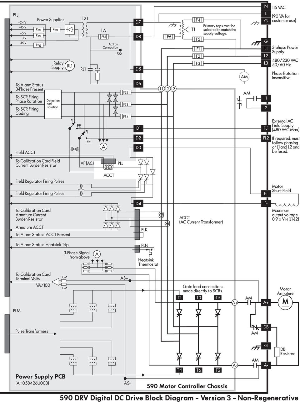
45 Figure Wiring Circuit Diagram for 590 DRV Digital Drive
46 Chapter 4 Start-up and Adjustment Chapter 4 START UP AND ADJUSTMENT The 590 DRV Digital drive is shipped with a default configuration designed to control a shunt or permanent magnet field DC motor. You can adjust the drive's parameters or change its configuration to achieve optimum performance and perform specific control applications. The drive can be tuned or configured using the drive s MMI, or by using a computer running the software package ConfigEd Lite. This chapter guides the user through the start up procedure using the MMI. Follow these procedures only after installing and wiring your 590 DRV Digital drive (see Chapter 3). Review Appendix B to become familiar with the MMI before proceeding. When an instruction refers to a MMI procedure, the menu levels are shown as a path with double colons :: delimiting each lower menu level, for example: SETUP PARAMETERS:: RAMPS:: ACCEL TIME RECOMMENDED TOOLS Equipment recommended to set up your 590 DRV Digital drive and tune a motor include: IBM compatible PC with Microsoft Windows 3.0 or greater to run ConfigEd Lite Oscilloscope to monitor armature current waveform and speed feedback Voltmeter to monitor motor armature and field voltage and check control signal levels Ohmmeter to check signal continuity Clamp-on, Hall effect ammeter to measure armature and field currents Digital hand tachometer to check line or motor speed WARNING! Confirm all wiring connections are correct before attempting start up procedures. 4 CHECK MOTOR After wiring and installing the 590 DRV Digital drive, make these motor checks before applying power. Motor Ratings Motor Wiring 1. Check and record nameplate information from the motor for future reference. 2. Verify that the motor wiring agrees with the motor installation drawings, if available. Be sure to check the motor field wiring. Some motors have two winding fields which require a series or parallel connection depending on the supply and torque requirements. Verify that the drive field supply output does not exceed the voltage rating of the motor field. If this voltage exceeds the field rating, supply the field power externally with the correct AC supply (refer to Figure 3.4 or 3.5 in Chapter 3). 3. Use an ohmmeter to check insulation and continuity on the motor's armature and field. Use the following as a guide for measuring continuity and resistance through the armature and field: Armature Resistance Field Resistance Insulation Checks Armature resistance < 1 W (about 3 W for motors rated under 10 HP). Field resistance = Motor nameplate field voltage Motor nameplate field current Insulation checks help ensure that there are no shorts in the motor. Use an ohmmeter set to its highest setting and measure the resistance between each conductor and ground. All readings should be greater than 10 MW. If available, use a megger to check for insulation faults in the motor armature and field windings. 590 DRV Digital Drive Product Manual 4-1
47 Chapter 4 Start-up and Adjustment Voltage & Current Calibration WARNING! Disconnect or isolate motor connections from the controller before performing a megger insulation, or high voltage tests on the motor windings. 4. Make sure all settings on the 590 DRV Digital drive calibration card are set to the correct values for your motor dataplate information (see the calibration card information in Chapter 3). Standard 590 DRV Digital drives up through 400 HP come equipped with a switch selectable calibration card; higher horsepower models require the resistor-adjustable calibration card. CHECK SUPPLY WARNING! Measure and verify the power supply to the drive before applying power to the input of the drive. Measure AC Supply Check Supply Against Motor Armature 1. Measure each leg of the three-phase power supply to ensure they are within ±10% of motor supply requirements. The controller has multiple ratings. Check whether the supply is suitable to attain the maximum desired armature voltage. Generally, the maximum armature voltage for a three phase DC drive is 110% of the AC supply voltage. A 240 VDC armature motor requires a 230 VAC supply; 500 VDC motor needs a 480 VAC supply. Consult the factory for other ratings. 4 Check Frequency Check Control Transformer Apply Power but do not Start Drive Field Voltage Should be Zero Check LEDs 2. If a frequency meter is available, measure the incoming line frequency. The frequency should not vary more beyond the acceptable range of 40 to 70 Hz. 3. Verify that the control transformer inside the 590 DRV Digital drive is tapped for the supply voltage. 4. Connect power but do not start the drive. The drive should now receive control power and the MMI display should read 590 DC DRIVE:: MENU LEVEL. Check the motor field voltage with a voltmeter once power is on. If the drive is supplying voltage to the motor field, the field should not receive power until the drive is started. 5. Check that the six diagnostic LED's show a normal stop condition (that is, the RUN and START LEDs are off with the other four LEDs illuminated) and that the motor is free to rotate. The PROGRAM and COAST STOP inputs (terminals B8 and B9) should be TRUE. INITIAL DRIVE START WARNING! Before starting the drive for the first time, make sure that your motor is uncoupled from the load, or ensure that the motor load can move without causing mechanical damage or danger to personnel. Verify 0% Speed Demand Check Program & Coast Stops Verify 0% Current Limit Start Drive Measure Field Voltage Measure Field Current 1. Give a 0% speed demand to the drive. Check all drive speed reference inputs in the MMI under DIAGNOSTICS:: SETPOINT SUM OUTPUT and SPEED SETPOINT. Ensure that the total speed setpoint to the drive is zero. 2. Set SETUP PARAMETERS:: CURRENT LOOP:: CURRENT LIMIT to 0.00%. 2. Ensure the PROGRAM STOP and COAST STOP LEDs are on (+24 VDC at terminals B8 and B9). 3. Set SETUP PARAMETERS:: CURRENT LOOP:: CURRENT LIMIT to 0.00%. 4. Start the drive by energizing terminal C3 (START/RUN). If the drive is wired to supply power to the motor field, measure the field voltage with a DC voltmeter and verify that it matches the motor nameplate rating. Measure the motor field current if a Hall effect current meter is available. If the motor field voltage or current is incorrect, follow the steps below to tune in the correct field supply DRV Digital drive Product Manual
48 Chapter 4 Start-up and Adjustment VOLTAGE CONTROL: Adjust RATIO WARNING! Failure to set up the field supply correctly can cause dangerous overspeed conditions resulting in serious equipment damage or injury to personnel. Do not continue the start up procedure until the DC field supply is within its required rating. FIELD IN VOLTAGE CONTROL: i. Set the field control mode to voltage control by setting SETUP PARAMETERS:: FIELD CON- TROL:: FLD CTRL MODE IS to VOLTAGE CONTROL. Check that the motor field current setting is calibrated for 0.2 amps. If using a resistor calibration card, make certain the field voltage calibration resistors R12 and R13 total to 100 kw. ii. Measure the field voltage on terminals F and F+ and verify that it equals the motor nameplate rating. iii.adjust SETUP PARAMETERS:: FIELD CONTROL:: VOLTAGE VARIABLES:: RATIO OUT/IN until the voltage equals field voltage rating on the motor nameplate label. iv.measure the motor field current if a Hall effect current meter is available. NOTE. Because a DC motor's field impedance increases with temperature, the field current of a motor in voltage control can read lower than the nameplate rating when the field is initially powered. The current should rise to its nominal value as the motor warms up. CURRENT CONTROL: Tune FIELD CURRENT CAL FIELD IN CURRENT CONTROL: i. Set the field control mode to current control by setting SETUP PARAMETERS:: FIELD CON- TROL:: FLD CTRL MODE IS to CURRENT CONTROL NOTE. FLD CTRL MODE IS must be set to CURRENT CONTROL when operating the motor in field weakening mode. Stop Drive ii. Measure the motor field current if a Hall effect current meter and adjust SETUP PARAMETERS:: CALIBRATION:: FIELD I CAL until the measured field current equals the field current rating on the motor nameplate label. 5. Stop the drive. 4 Save Parameters 6. If any changes were made to the drive's parameters settings, SAVE PARAMETERS. ADJUST CURRENT LOOP (AUTOTUNE) Caution This is an essential step in setting up your 590 DRV Digital drive and should not be overlooked. The AUTOTUNE function tunes the current loop automatically and sets the proportional gain, integral gain, and the discontinuous/continuous breakpoint for optimum drive response for a given motor. The drive cannot achieve peak performance without properly setting these parameters. Perform a complete AUTOTUNE procedure at least once with each controller/motor combination, or if the motor armature or field windings have been rewound. NOTE. AUTOTUNE may not work on motors with either very long or very short time constants (for example, very short time constant permanent magnet motors). In these instances the current loop must be tuned manually. Contact Eurotherm Drives Customer Service for assistance. AUTOTUNE can be used for shunt-wound, compound-wound, and permanent magnet motors. The shaft on compound-wound and permanent magnet motors must be locked for AUTOTUNE to work. For shunt wound motors, the shaft may need to be clamped if a residual field causes the motor to rotate during AUTOTUNE. Any rotation of the motor during the AUTOTUNE procedure causes AUTOTUNE to abort. 590 DRV Digital Drive Product Manual 4-3
49 Chapter 4 Start-up and Adjustment AUTOTUNE Procedure WARNING! Make sure it is safe to power and turn the motor and that operation of the motor and the drive will not pose a danger to personnel or equipment. Stop Drive Disconnect Main Power Clamp Shaft if PM Motor Apply Power Disable Drive Set Main Current Limit to 100% Start Drive Enable AUTO- TUNE Enable Drive 1. Stop the drive (remove the START/RUN signal) then disconnect the main supply power. 2. The motor shaft may need to be clamped to prevent rotation during the AUTOTUNE procedure. If you are using a permanent magnet motor, it must be clamped. 3. Turn on the main supply power. Make sure the PROGRAM STOP and COAST STOP LEDs are on (+24 VDC at terminals B8 and B9). 4. Disable the drive by removing +24 VDC from terminal C5 (ENABLE). This can also be done with the MMI under SETUP PARAMETERS:: AUX I/O. 5. Set SETUP PARAMETERS:: CURRENT LOOP:: CURRENT LIMIT to 100%, the MMI default setting. 6. Start the drive, then enable AUTOTUNE by setting SETUP PARAMETERS:: CURRENT LOOP:: AUTOTUNE to ON. The drive should start but should not generate motor current. 7. Enable the armature current. At this point, the drive performs the AUTOTUNE function automatically, setting the following parameters: a. SETUP PARAMETERS:: CURRENT LOOP:: PROP. GAIN b. SETUP PARAMETERS:: CURRENT LOOP:: INT. GAIN c. SETUP PARAMETERS:: CURRENT LOOP:: DISCONTINUOUS These parameters give optimum performance of the current loop and should not be adjusted outside the AUTOTUNE algorithm. 4 Remove Mechanical Clamp 8. Once AUTOTUNE is finished, the main contactor should open automatically, signaling the end of the procedure. The controller returns to a safe, stopped condition with the HEALTH, RUN and START CONTACTOR LED's turned off. If the motor rotates during the procedure, AUTOTUNE ceases automatically causing an AUTOTUNE FAILURE alarm. Removing the RUN or ENABLE signals during AUTOTUNE also aborts this procedure (in both cases, the armature current is disabled and the main contactor opens). 9. Remove the clamp, if fitted, from the motor. Save Parameters 10.SAVE PARAMETERS when finished. Armature Current Waveform Check Because there is no field voltage, the drive conducts full load current through the armature during an AUTOTUNE. You can monitor the armature current waveform with an oscilloscope to verify correct operation of the controller. Attach the oscilloscope leads to the Armature Current test point and the Sig. Ground test point. Refer to Figure 5.21 in Chapter 5 for the drive's test point locations. At full rated current, the armature current signal should average 5.0 volts. There should be six current pulses per mains cycle at all times. The pulses should be uniformly shaped and evenly spaced (see Figure 5.1), each with a width of 2.8 ms on 60 Hertz supplies, and 3.3 ms on 50 Hertz supplies. Figure Armature Current Waveform DRV Digital drive Product Manual
50 Chapter 4 Start-up and Adjustment MOTOR ROTATION CHECK This procedure verifies that the motor shaft rotates in control and in the desired direction. Set I limit to 0% Start Drive Set Speed Demand to 10% Increase I limit to 20% DC Tach AC Tach 1. Set SETUP PARAMETERS:: CURRENT LOOP:: CURRENT LIMIT to 0%. 2. Start the drive and set your drive speed reference potentiometer to +1.0 VDC or +10%. Make certain that any trim speeds or additional setpoints are set to 0%. Check that DIAGNOSTICS:: SPT. SUM OUTPUT is indeed +10%. You can monitor all the drive's speed references under SETUP PARAM- ETERS:: SPEED LOOP:: SETPOINTS. 3. Slowly increase SETUP PARAMETERS:: CURRENT LOOP:: CURRENT LIMIT to approximately 20%. 4. The motor speed should increase to 10% speed in the desired direction. If the feedback or field polarity is incorrect, the motor will either run away, or run in control in the wrong direction. If either situation occurs, stop the drive, disconnect the main supply and external field supply (if used) and check the following: a. For motors fitted with analog DC tachometer generators: Did the motor run away in the correct direction? Reverse the tachometer generator wires. Did the motor run away in the wrong direction? Reverse the field connections. Did the motor rotate in the wrong direction but at the correct speed? Reverse both the field and tachometer generator connections. b. For motors fitted AC tachometer generators: Did the motor run away in the correct direction or in the wrong direction? Reapply power and check the speed setpoint. Because an AC tachometer generator provides a unipolar output regardless of direction of rotation, the drive is limited to speed control in one direction only. This speed reference must be positive. If the motor ran away in reverse, provide a positive speed reference and reverse the field connections. NON-regen only for AC Tachs Caution A runaway condition always exists when using an AC tachometer generator on a regenerative model DC controller, even if the speed reference is always positive. To avoid this problem, use the 591SP (non-regenerative) drive on a motor with an AC tachometer generator. Or, use the regenerative 590 DRV Digital drive and disable the drive's reverse bridge thyristors under SETUP PARAMETERS:: CURRENT LOOP:: REGEN MODE. 4 Microtach/ Encoder Did the motor rotate in the wrong direction but at the correct speed? Reverse the field connections. c. For motors fitted with 5701/5901 Microtachs or wire-ended electrical encoders: Did the motor run away in the correct direction? Reconnect the drive supply and change the feedback sign by setting SETUP PARAMETERS:: SPEED LOOP:: ENCODER SIGN to POSI- TIVE or NEGATIVE as required. Did the motor run away in the wrong direction? Reverse the field leads. Did the motor rotate in the wrong direction but at the correct speed? Reverse the field connections, reconnect the drive supply and reverse the feedback sign by setting ENCODER SIGN to POSITIVE or NEGATIVE as required. Caution When changing set up parameters (such as feedback polarity), be certain to save the change before disconnecting control power or the set up will be lost. 590 DRV Digital Drive Product Manual 4-5
51 Chapter 4 Start-up and Adjustment No feedback signal? Motor Does not turn? Increase I Limit Check Connections Check Reversing if Applicable Reset I Limit Stall Trip Save Parameters 5. If the motor continues to run away after checking the feedback sign and field polarity check whether the drive actually receives it speed feedback signal. Monitor DIAGNOSTICS:: TACH VOLTS when using an analog tachometer generator. For Microtach or wire-ended encoders, check DIAGNOSTICS:: ENCODER RPM. Verify the connections and supply wiring to the feedback device if it fails to generate a feedback signal. If the drive trips on either SPEED FEEDBACK alarm or ENCODER FAILED alarm, verify that the SPDFBK ALARM LEVEL, ENCODER RPM and ENCODER LINES parameters are properly set. 6. If the motor does not turn at all, increase the CURRENT LIMIT to 50% or greater and monitor DIAG- NOSTIC:: CURRENT FEEDBACK. If CURRENT FEEDBACK still reads 0.00%, turn the power off and check the armature connections. If the problem persists, refer to Chapter 7 for detailed troubleshooting information. 7. If the drive is regenerative and the application requires reverse rotation, provide a negative speed demand, start the drive and verify that the motor runs in the reverse direction. 8. After you have correctly set the direction of rotation, reset CURRENT LIMIT to the desired value. If in doubt, set CURRENT LIMIT to 110% to correspond to 110 % full load current. If CURRENT LIMIT is set to a maximum 200%, and the motor runs into an overload condition, the current limit automatically reduces on an inverse time curve from the overload level down to 110% full load current. NOTE. The motor may overheat if it continues to rotate while at current limit. Thermal protection should be provided. If the motor is overloaded and there is insufficient controller current to maintain rotation, the motor will stall, and the controller will trip out on the STALL TRIP alarm if this alarm is enabled. 9. Stop the drive then SAVE PARAMETERS. SPEED FEEDBACK CALIBRATION 4 Start Drive Run at half speed Monitor Armature Volts Run at full speed Monitor speed with hand tach Armature Voltage Feedback Coarse scale: Set Voltage Calibration Fine tune: Set ARMATURE V CAL IR Compensation Start the drive, gradually increase the speed demand signal to 50% and monitor DIAGNOSTICS:: TERMI- NAL VOLTS. Measure the armature voltage on the drive output with a DC voltmeter. TERMINAL VOLTS should read within 10% of the actual value. For example, when measuring armature volts at terminals A+ and A- with a voltmeter, a 500 VDC armature should read 250 VDC at 50% speed demand and TERMINAL VOLTS should be within 45 to 55%. If the reading is outside this range, check the drive's voltage calibration before continuing. Increase the speed demand to 100% and check the shaft speed accuracy with a hand tachometer. Measure the armature voltage. If fine adjustment is needed, adjust the drive's calibration according to the speed feedback selection. 1. ARMATURE VOLTAGE FEEDBACK Armature voltage feedback uses the motor's back EMF as speed feedback and is the drive's default feedback setting. It requires no feedback device, isolator or additional external connections. The scaling parameter, SETUP PARAMETERS:: CALIBRATION:: ARMATURE V CAL, fine tunes the drive's armature voltage calibration and has a range of to , corresponding to -10% to +2% trim. Changes outside this range require re-calibration as described in Chapter 3. IR COMPENSATION SETUP Properly setting the IR COMPENSATION parameter, or motor loss compensation, improves the speed accuracy when running in armature voltage feedback. Run the motor without a load. Monitor the actual speed with a hand tachometer. With the same speed setpoint, run the motor at full load and monitor the actual speed again with a hand tachometer. Adjust IR COMPENSATION until the full load speed is the same as the no load speed. NOTE. Too much IR COMPENSATION causes instability DRV Digital drive Product Manual
52 Chapter 4 Start-up and Adjustment Microtach Adjust ENCODER LINES Adjust ENCODER RPM Analog Tach Coarse scale: Set Cal Card Switches Monitor Speed with Hand Tach Fine tune: Set Analog Tach Cal Nonlinear? Set ANALOG TACH +/-CAL 2. MICROTACH or WIRE-ENDED ELECTRICAL ENCODERS Ensure that the CALIBRATION:: ENCODER LINES parameter equals the pulses per revolution rating of the encoder (1000 for Microtachs). You can read the feedback encoder rpm under DIAG- NOSTICS:: ENCODER RPM in the MMI or in SAM under the FEEDBACK software block. Adjust the calibration parameter SETUP PARAMETERS:: CALIBRATION:: ENCODER RPM to accurately tune the motor rotational speed to the roll speed with a hand tachometer. Either feedback device gives an absolute rotational speed for which adjustment is unnecessary; however, the process may require an accurately set speed calibration. Speed match the motor through the ratio calculation: New ENCODER Rpm Setting = Present ENCODER Rpm Setting x 3. AC/DC ANALOG TACHOMETER GENERATOR Desired Rpm Measured Rpm Settings on the analog tachometer generator feedback option card or resistor values on the resistor calibration card give a coarse scaling of the analog tachometer generator feedback voltage. Fine tune the feedback by adjusting drive software parameters. Use a hand tachometer to measure the motor speed and adjust SETUP PARAMETERS:: CALIBRA- TION:: ANALOG TACH CAL to scale the overall feedback. Speed match the motor through the ratio calculation: New ANALOG TACH CAL Setting = Present ANALOG TACH CAL Setting x Desired Rpm Measured Rpm The gain range varies from to , or -10% to +2% trim. Changes outside this range require a re-calibration of the feedback calibration card as described in Appendix A. Use CALIBRATION:: ANALOG TACH -CAL and ANALOG TACH +CAL to tune out a nonlinear analog tachometer generator response only. Adjust ANALOG TACH +CAL for a non-linearity at the positive high volt (full speed forward) end of the response curve; change ANALOG TACH -CAL to tune out a non-linearity at the negative high volt (full speed reverse) end. These parameters vary over a range of to , but are generally left at Zero Offset? Set ANALOG TACH ZERO Save Parameters NOTE. It is usually unnecessary to change the ANALOG TACH -CAL and the ANALOG TACH +CAL parameters from their default value of , except in cases of extreme nonlinearity. For a tachometer whose observed accuracy is within the tachometer's rated accuracy, adjustment is not recommended and will complicate speed calibration. Some tachometer generators generate a nonzero voltage at zero speed. Use ANALOG TACH ZERO to tune out the offset. 4. SAVE PARAMETERS when finished. 4 SETUP FOR FIELD WEAKENING If the motor requires field weakening to achieve top speed, follow these steps. NOTE. Field weakening requires tachometer generator, wire-ended or Microtach encoder speed feedback. Check Field Current Calibration Enable Field & Check mode is CURRENT CONTROL 1. With no power supplied to the drive, set the field current calibration on the switchable or resistor calibration card as described in Chapter 3. Many field weakened motor give the field current as two values, a minimum and a maximum, indicating the field weakened range of the motor. Calibrate the motor field for the larger of these two values. 2. Set SETUP PARAMETERS:: FIELD CONTROL:: FIELD CTRL MODE IS to CURRENT CONTROL and verify the field is enabled by monitoring parameter SETUP PARAMETERS:: FIELD CONTROL:: FIELD ENABLE. 590 DRV Digital Drive Product Manual 4-7
53 Chapter 4 Start-up and Adjustment Enable FIELD WEAKENING Set MIN FIELD CURRENT Set MAX VOLTS to 100% Base Speed Increase above base speed & speed track, if necessary Check Reverse Speed Save Parameters 3. Verify that SETUP PARAMETERS:: FIELD CONTROL:: FLD CURRENT VARS:: FLD WEAK VARS:: FLD WEAK ENABLE is ENABLED: 4. Ensure that SETUP PARAMETERS:: FIELD CONTROL:: FLD CURRENT VARS:: FLD WEAK VARS:: MIN FLD CURRENT is set correctly for the motor to reach top speed. MIN FLD CURRENT is calculated using the formula: (minimum field current maximum field current) 90% This sets MIN FLD CURRENT 10 percent lower than the field calculated to reach full speed. The minimum and maximum field currents are found on the motor nameplate label. The 10 percent cushion should overcome any inaccuracies in the nameplate data. 5. Adjust the maximum armature volts to 100 percent using parameter SETUP PARAMETERS:: FIELD CONTROL:: FLD CURRENT VARS:: FLD WEAK VARS:: MAX VOLTS. 6. Run the drive up to base speed. Monitor DIAGNOSTICS:: TERMINAL VOLTS to verify that the armature voltage is approximately equal to the value calculated in the previous step. 7. Increase speed above base speed by adjusting the speed potentiometer, checking that the motor armature volts remain constant while the field gradually decreases. Gradually increase to maximum speed, monitoring armature volts at maximum speed. Adjust the speed using the appropriate speed feedback calibration parameters, for example ANALOG TACH CAL when using analog tachometer generator feedback. 8. For regenerative, reversing drives, check the maximum reverse speed. Correct any asymmetry in a reversing drive by adjusting SETUP PARAMETERS:: CALIBRATION:: ZERO SPD. OFFSET. 9. Stop the drive and SAVE PARAMETERS. 4 ADJUST SPEED LOOP After calibrating the motor speed, tune the speed loop proportional gain (PROP. GAIN) and integral time constant (INT. TIME CONST) settings for optimum speed response. For this procedure, monitor the speed feedback with an oscilloscope at the Analog Tach test point pin on the control board (refer to Figure 5.19 in Chapter 5). NOTE. Adjust the speed loop only after tuning the current loop with AUTOTUNE. Make certain the motor is connected to the load it will normally be running. PROP. GAIN scales the output based upon the input speed error. Increasing PROP. GAIN improves response time but also increases overshoot. INT. TIME CONST eliminates steady-state error. Reducing INT. TIME CONST improves response, but will cause instability if set too short. Apply +10 VDC to A3 thru Switch Set A3 (INPUT 2 CAL) = Set Integral defeat ON Set INPUT 3 (A4) = +5 VDC Switch +10 VDC to A3 Adjust P Gain 1. Connect terminal B3 (+10 VDC) through a switch to terminal A3. This will provide the step change input for verifying speed loop performance. 2. Calibrate terminal A3 for 10% output by setting SETUP PARAMETERS:: SPEED LOOP:: SETPOINTS:: RATIO 2 (A3) to Set SETUP PARAMETERS:: SPEED LOOP:: INT. DEFEAT to ON. This disables the integral gain. 4. Run the motor at a typical operating speed through the speed ramp input, terminal A4. The speed should not exceed 50 percent. 5. Check the speed loop performance by making step changes using the switch at terminal A3. Increase SETUP PARAM- ETERS:: SPEED LOOP:: PROP. GAIN until the response is critically damped as illustrated above. Figure Response to Step Input DRV Digital drive Product Manual
54 Chapter 4 Start-up and Adjustment Monitor Response Turn integral defeat OFF Adjust I Gain Stop Drive. Remove Switched +10 VDC at A3. Set INPUT 2 CAL = Save Parameters 6. Once stable proportional control is attained, set SETUP PARAMETERS:: SPEED LOOP:: INT. DEFEAT to OFF. 7. Check the speed loop performance by making step changes using the switch at terminal A3. Reduce SETUP PARAMETERS:: SPEED LOOP:: INT. TIME CONST until the response is critically damped. NOTE. The default value for INT. TIME CONST is 0.5 seconds. That value may be too small for large inertia loads and cause the system to be unstable from the start. 8. Stop the drive and remove the switched signal from terminal A3. 9. Reset the calibration for terminal A3 back to 100% by setting SYSTEM:: CONFIGURE I/O:: ANA- LOG INPUTS:: ANIN 2 (A3) to , then run normally. 10. SAVE PARAMETERS. OTHER PARAMETERS Other parameters, for example ramp rates, may be important for the process. Different ramp rates are available for various conditions: Condition Parameter Name Menu Speed Setpoint Change RAMP ACCEL TIME and RAMP DECEL TIME RAMPS Jog Acceleration/Deceleration RAMP RATE JOG/SLACK Controlled Stop Deceleration STOP TIME STOP RATES Fast Stop Deceleration PROGRAM STOP TIME STOP RATES Electronic MOP Control INCREASE RATE and DECREASE RATE RAISE/LOWER Appendix C fully discusses the functionality and scaling of all drive parameters. RECORDING PARAMETERS It is important to have a hard copy of your drive parameters. This copy might consist of writing down the information on a chart, saving the parameters to a computer disk, or printing the parameters using an external computer. The parameter list in Appendix C has two empty columns for manually recording the drive parameters. 4 To save the parameters as either a hexadecimal ASCII file or as a text file ready for printing, connect a computer to the P3 serial port. Use a telecommunications program, such as Procomm, Windows Terminal, or other terminal emulation programs. Refer to "Using Microsoft Windows to Document and Clone 590 DRV Digital Drives" (HA352155) for detailed instructions using Windows Terminal for uploading and downloading drive parameters. Appendix G also contains general information for using P3 to upload and download drive parameters. PASSWORD PROTECTION To safeguard the parameters you have set with the MMI, you can configure the 590 DRV Digital drive in a passwordprotected mode. At the initial power up, the DISPLAY PASSWORD command is automatically cleared to zero. If the controller password is set at any value other than zero, the MMI is in a restricted mode and the MMI display can be displayed but not altered. Entering a Password To access the password configuration procedure from the main menu: PASSWORD M to enter the Password sub-menu M to enter the ENTER PASSWORD sub-menu to enter the password on the screen. 590 DRV Digital Drive Product Manual 4-9
55 4 Chapter 4 Start-up and Adjustment Changing a Password All 590 DRV Digital drives are shipped with the default password 0x0000 which is displayed in the MMI. If the default password does not work, contact your supplier for the new password. Once you have entered the correct code, you may use the CHANGE PASSWORD function to set your own restricted password. PASSWORD M to enter Password sub-menu to CHANGE PASSWORD M to enter the CHANGE PASSWORD sub-menu to enter a different value (password) E to back out one step to move to CLEAR PASSWORD display M to clear the password This clears from view the password you have entered, protecting the settings from those without access to the password. With password protection installed in your 590 DRV, the parameters available through the MMI can be viewed but not be altered without first entering that password. To edit parameters, you must reenter the password and repeat the procedure described above. 4-Button Reset NOTE. Be sure to record the new password. If you lose your password, you will be unable to change parameters. A 4-Button Reset loads the drive's default parameters into the drive's operating memory; erasing all customized settings and connections. It is often used to reset the drive when troubleshooting procedures fail. See Appendix B for more information on using the MMI and performing a 4-Button Reset DRV Digital drive Product Manual
56 Chapter 5 Troubleshooting Chapter 5 TROUBLESHOOTING The most valuable tools for finding and resolving faults are the MMI and the LED display. You can also monitor alarms and troubleshoot faults remotely through a computer interface if a RS422 serial communications option card (AH385826U001) is installed on the drive. INITIAL TROUBLESHOOTING PROCEDURE Most drive problems are encountered during commissioning or soon after start-up. Problems frequently result from incorrect installation or errors in configuring the drive. If you encounter a problem upon initial start up of your 590 DRV Digital drive, review the installation procedures in Chapter 3 and the start up and adjustment procedures in Chapter 4. If you have reviewed your installation and initial start up procedures and all seems to be in order, proceed to the troubleshooting methods in this chapter. Use the flowchart in Figure 5.1 to begin troubleshooting. 5 Figure Initial Troubleshooting Procedure 5-1
57 5 Chapter 5 Troubleshooting Recommended Tools You will need the following tools for most troubleshooting procedures: Voltmeter Megger If available, the following tools can provide more detailed information for problem-solving: Oscilloscope Hand tachometer You may also need screwdrivers and/or wrenches to restore electrical connections that are incorrect or have come loose. STATUS LED TROUBLESHOOTING Six light emitting diode [LED] indicators are located just to the right of the MMI display. The LEDs indicate six status conditions on the drive: health, run, start contactor, overcurrent trip, program stop, and coast stop. LED Functions The HEALTH and RUN LEDs are software driven. The health LED turns ON when control power is applied and remains ON if the drive passes all 18 diagnostic alarm points the drive continuously monitors while running. If an alarm fault occurs, the drive's MMI displays the associated alarm message and the HEALTH LED turns off. The RUN LED turns ON after the following sequence occurs: the drive receives start command through the RUN or JOG input (terminals C3 or C4), the drive is healthy, the thyristor bridge circuit enables and the start contactor energizes. The RUN LED turns OFF whenever the drive is disabled. This LED also turns OFF if the drive's internal start relay de-energizes, or if a fault occurs. The four remaining LEDs START CONTACTOR, OVERCURRENT TRIP, PROGRAM STOP, and COAST STOP are hardware driven. The START CONTACTOR LED is ON whenever the drive's internal start relay is energized. PROGRAM STOP and COAST STOP are ON whenever +24 VDC is connected to terminals B8 (PRO- GRAM STOP) and B9 (COAST STOP). These terminals are normally switched to terminal C9 +24 VDC through an external emergency stop relay. Figure Sample LED Status Modes 5-2
58 Chapter 5 Troubleshooting All six LEDs are ON under normal running conditions. Figure 5.2 shows the LED states after common actions and other faults occur. An unlit LED indicates a problem that prevents controller operation and requires user attention. The table in Figure 5.3 shows what to check when an LED is off. LED NAME MEANING WHEN OFF POSSIBLE CAUSE CORRECTIVE ACTION HEALTH RUN Fault has occurred and is shown by the other LED status' and the MMI display. The drive is not enabled or in the RUN state. Any of the drive's possible fault conditions. START CONTACTOR The start contactor is open. 24 VDC signal is not present at terminal C3. OVERCURRENT TRIP Armature current has exceeded 300 The armature is calibrated wrong. percent full load. Mechanical binding on the motor is preventing free movement. Field voltage too low. PROGRAM STOP COAST STOP 24 VDC signal not present at terminal B8. The main contactor will drop out once the motor has completed a controlled stop. 24 VDC signal not present at terminal B9. The main contactor is de-energized and the motor will coast to a stop. Check the MMI for alarms. Go to the ALARM MESSAGES section for troubleshooting tips. The thyristor bridge is disabled Check all enable input (terminal C5) circuitry. The main contactor is de-energized. Check for loose wires from the drive to the contactor coil. Another alarm is present. Go to the ALARM MESSAGES section for troubleshooting tips. Check the RUN circuitry. Check the armature current calibration on the calibration board. Inspect motor couplings, linkages, bearings, etc. Check field supply and verify motor field voltage. Emergency stop is engaged or other Ensure the "B" terminal block is fully external logic or safety interlocks are engaged on the control door. preventing 24 VDC from being Check all safety interlocks in the external present at B8. logic. 24 VDC supply has failed. Check for 24 VDC at terminal C9 or the external 24 VDC supply if used. Emergency stop is engaged or other Ensure the "B" terminal block is fully external logic or safety interlocks are engaged on the control door. preventing 24 VDC from being Check all safety interlocks in the external present at B9. logic. 24 VDC supply has failed. Check for 24 VDC at terminal C9 or the external 24 VDC supply if used. Figure Status LED Troubleshooting Procedures 5 5-3
59 Chapter 5 Troubleshooting HEALTH, ALARM MESSAGES AND THE TRIP RESET The controller continuously monitors 19 alarms while the drive is running. These alarms are gated together to provide an overall "controller healthy" logic variable. This variable corresponds to the ALARM STATUS software block output HEALTHY (tag number 122). The default shipped drive configuration of the 590 DRV Digital drive tags the HEALTHY logic parameter to digital O/ P 2 (terminal B6). If a fault occurs while the controller is running, HEALTHY switches FALSE and the drive immediately inhibits the thyristor firing circuit. The drive then deenergizes the main contactor and the MMI displays the last fault registered, or the fault which interrupts controller operation. If TRIP RESET (parameter tag 305 set under the SETUP PARAM- ETERS:: INHIBIT ALARMS menu) is TRUE, the HEALTHY output remains FALSE until the RUN input (terminal C3) switches LOW, as shown in the left portion of Figure 5.4. Figure HEALTHY Output Logic If a restart is attempted without first clearing the fault, HEALTHY will again switch FALSE and the drive will not enable the thyristors and reenenergize the main contactor. If TRIP RESET is FALSE, the drive cannot restart regardless of the state of the RUN input or whether or not the fault is cleared. The tables in Figures 5.5 through 5.10 describe the different alarms the MMI displays when the drive trips out on a fault, the fault's symptoms and recommended corrective action. DISPLAY MESSAGE MEANING POSSIBLE CAUSE CORRECTIVE ACTION *** ALARM *** 3 PHASE FAILED One or more phases of the 3 phase Supply voltage low or a phase is supply is missing, or below 208 volts. missing. Check 3 phase input voltages L1, L2, L3. Blown fuse. Check fuses F1, F2,F3, FS4, FS5, and FS6 and external line fuses. Check armature current calibration does not exceed drive rating. Check all power wiring for tightness. Loose wiring. Defective power supply pcb. Replace power supply pcb. 5 *** ALARM *** ACCTS FAILED ACCT (Alternating Current Current Transformer) armature feedback sensing hardware interlock not made. Plug PLK not inserted or output wires of ACCT severed. Insert PLK in socket on power supply PCB. Check output wires of ACCT. *** ALARM *** AUTOTUNE ABORTED Enable, or Start/Run commands removed before AUTOTUNE procedure completed. Wrong AUTOTUNE sequence followed. AUTOTUNE incomplete. (After 2 minutes drive will time out if still in AUTOTUNE mode). Calibration card missing or improperly fitted. Repeat AUTOTUNE procedure. Repeat AUTOTUNE procedure. If problem persists contact Eurotherm Drives customer service. Check that calibration card if fully inserted on mounting pins on control door. *** ALARM *** CAL CARD Calibration hardware interlock not made. Figure Alarm Messages 5-4
60 Chapter 5 Troubleshooting DISPLAY MESSAGE MEANING POSSIBLE CAUSE CORRECTIVE ACTION *** ALARM *** AUTOTUNE ERROR Motor rotation detected during Autotune process (speed feedback greater than 20%), or Field current detected during AUTOTUNE. (Field current greater than 6%). Residual motor flux when field regulator disabled. Series field winding connected in motor. Lock motor armature and repeat AUTOTUNE procedure. Series fields are not recommen- ded for regenerative drives and the series field winding should normally be left open circuit. If a series field is required, either lock the motor shaft or temporarily disconnect the series field and repeat the AUTOTUNE procedure. Lock motor armature and repeat AUTOTUNE procedure. Disable external field supply and repeat AUTOTUNEing procedure. On older units fitted with a diode bridge field supply the field wiring must be disconnected to achieve zero current for AUTONE purposes. Check that encoder or Microtach feedback card is properly fitted to the control door. If using an anlog tachometer or armature voltage feedback, make sure that the SPEED FEEDBACK SELECT parameter is set to ANALOG TACH or ARM VOLT FBK. Check the fiber optic cable run for bends, kinks and continuity. Ensure that the cable installation does not exceed bend radius of fiber optic cable. Permanent magnet motor. Separately supplied field. Old style power chassis with field diode bridge. *** ALARM *** ENCODER FAILED Feedback hardware removed or not fitted when ENCODER FEEDBACK has been selected, or Microtach feedback has fiber optic overdrive, underdrive, or phase lock alarm when Encoder Feedback has been selected (see Microtach Feedback). Encoder or Microtach feedback option card incorrectly fitted to control door. Fiber optic cable too long or cable distorted (bend radius too small for example) resulting in too weak a signal at Microtach receiver [under drive]. Fiber optic cable too short resulting in too strong a signal at Microtach receiver [over drive]. PLASTIC CABLE: back cable slightly out of hardened input receiver and retighten. GLASS CABLE: attenuate fiber optic signal with longer cable run or by setting (if used) the 5702 or 5904 repaeater launch power to lower setting. Check integiry of wiring from drive to motor. Check for continuity, proper termination and insulation wear. Disable field using parameter FIELD ENABLE in SETUP PARAMETERS::FIELD CONTROL. Repeat field supply set up procedure in Chapter 5 [see INTIAL DRIVE START and SETUP FOR FIELD WEAKENING]. Check FS4, FS5 or external AC field supply fuses if fitted. Verify motor rating plate current does not exceed drive field current output capability. Check motor field winding resistance. Using a megger, check field wiring for a possible short to ground. Replace defective field thyristor block. *** ALARM *** FIELD FAILED Field current below 6% in Current Control Mode, or below 12% in Voltage Control Mode. Field circuit open or shorted. Using permanent magnet motor. Drive field current miscalibrated. Field supply fuse blown. 5 Field thyristor block defective. Power supply board failed. External field supply connected incorrectly. Figure Alarm Messages (Continued) Disable field fail alarm by setting SETUP PARAMETERS::INHIBIT ALARMS::FIELD FAIL to INHIBIT. Set MAIN I LIMIT to 0.00%, then start drive and measure field voltage and current. If present, replace power supply board. Check the external field supply phasing [see WIRING PROCEDURES in Chapter 3]. 5-5
61 Chapter 5 Troubleshooting DISPLAY MESSAGE MEANING POSSIBLE CAUSE CORRECTIVE ACTION *** ALARM *** FIELD OVER I Field over current. Field current exceeds 120% (alarm only operates if field is in Current Control Mode). Drive field current miscalibrated. External field supply connected incorrectly. Repeat field supply set up procedure. Check the external field supply phasing (see Chapter 3). *** ALARM *** HEATSINK TRIP Heatsink thermostat open; drive overheated. Fan failure or obstruction. Check drive fan rotating (when fans fitted). Fan fuse blown. Check FS1. Plug PLN not fully inserted. Check heatsink plug PLN fully inserted in power supply pcb. Inadequate enclosure ventilation. Check enclosure fan and filter. Check location of drive meets manual installation requirements. Extreme ambient temperature. Measure enclosure internal temperature. Fit ventilation fans or air conditioning if ambient exceeds drive specification [see VENTILAION & COOLING REQUIREMENTS in Chapter 3]. Drive miscalibrated. Check drive calibration. Mis-calibration can cause overheating. INITIALIZING IA FBK CAL FAIL Armature current feedback calibration fail during the power-up self test. Armature current feedback current transformers miswired. Control board defective. Check ACCT wiring and PLK jumpers on the power supply board. Replace control board. *** ALARM *** MISSING PULSE Missing armature current pulse. Irregular armature current waveform detected. (Armature current must be 1.5 times the discontinuous current level and missing pulse must be present for 60 seconds for alarm to operate). NOTE. Ripple from the speed loop can cause unstable current. Drive not AUTOTUNEd (Unstable current loop). SCR gate connection loose. SCR defective. SCR firing pcb defective. Motor has opened or shorted coil. Coupling between motor and feedback device slipping Feedback device noisy or defective. Bottom two LEDs on the 5701 or 5901 Microtach receiver board are out. Speed loop gain too high. Perform the AUTOTUNE procedure. Check SCR gate connections from the trigger board to the SCR gate leads. Check SCRs with an ohmmeter: See SCR Troubleshooting in this chapter. Replace the pcb. Check the motor with an ohmmeter and megger for insulation and continuity. Stop drive and isolate power. Check coupling tightness. Replace tachometer generator if noise is present while observing feedback with an oscilloscope. Weak feedback signal intensity; check connections, fiber optic wire integrity, and transmission distances. Retune drive speed loop Figure Alarm Messages (Continued)
62 Chapter 5 Troubleshooting DISPLAY MESSAGE MEANING POSSIBLE CAUSE CORRECTIVE ACTION *** ALARM *** OVER I TRIP Armature over current trip. Armature current has exceeded 300% of calibration value. Drive not AUTOTUNEd (Unstable current loop). The drive AUTOTUNE procedure MUST be followed for the motor the drive is to control. Repeat the AUTOTUNE procedure. Drive incorrectly calibrated. Check the calibration settings. Manual tuning of drive leaves current loop unstable. Current loop response may be manually adjusted only AFTER AUTOTUNing is complete. Check current loop response. THIS IS NOT RECOMMENDED! Coupling between motor and feedback device slipping. Stop drive and isolate power. Check coupling tightness. Motor armature faulty. Check motor resistance to ground. Check for armature shorts. Loss of 3 phase supply during regeneration. Check 3-phase supply branch circuit protection and SCR fuses, F1, F2, and F3. ENABLE (A5) activating before DRIVE START when using a DC contactor. Activate ENABLE (A5) with auxiliary contact off DC contactor. Check for other wires at terminal A5. Control Door or Power Supply PCB faulty. Replace defective board. *** ALARM *** OVER SPEED Drive speed feedback exceeded 125% of calibrated value. Improperly set maximum speed parameters. Use hand tachometer to ensure proper speed and adjust the speed calibration parameter. Wrong type of feedback selected in SPD FDBK SELECT parameter in MMI. Change parameter to match feedback type. Calibration board set incorrectly for analog tachometer generator feedback. Verify calibration resistors, R6 and R7 or the switchable calibration board settings. Check AC/DC tach switch. Improper calibration of drive speed feedback, encoder ppr selection for example. Recalibrate the speed feedback. Set ENCODER LINES to proper ppr of feedback encoder. Improper tuning of speed loop parameters drive overshooting or unstable. Retune drive speed loop (see Chap 5). Coupling between motor and feedback device slipping. Stop drive and isolate power. Check tightness of coupling. Feedback device noisy or defective. Replace tachometer generator. Use scope & check for noise. Bottom two LEDs on the 5701 or 5901 Microtach receiver board are out. Weak feedback signal intensity; check signal db, connections, fiber optic wire integrity, and transmission distances. Field weakening parameters incorrectly set. Reconfigure the field weakening parameters as described in Chapter 5. Drive operating as current regulator. Check external speed loop adjustments. 5 Figure Alarm Messages (Continued) 5-7
63 Chapter 5 Troubleshooting DISPLAY MESSAGE MEANING POSSIBLE CAUSE CORRECTIVE ACTION 5 *** ALARM *** OVER VOLTS (VA) *** ALARM *** PHASE LOCK *** ALARM *** SPD FEEDBACK Armature voltage exceeded 120% of calibrate value. Drive SCR firing phase lock loop unable to lock to supply waveform. Difference between armature voltage and speed feedback signals exceeded speed feedback alarm threshold setting, or Tachometer feedback signal wrong polarity. Drive miscalibrated for motor armature voltage. Drive miscalibrated for field voltage ratio [voltage mode] or field current [current or field weakening mode]. Armature open circuit. Motor maximum speed set incorrectly causing armature voltage to exceed nameplate rating Field weakening parameters set incorrectly if using an extended speed range motor. One or more phases of supply low, too high or missing. Supply waveform badly distorted. Power supply pcb or control door defective. Supply frequency outside Hz range. Wrong polarity speed feedback signal. Armature volts miscalibrated. Tachometer generator miscalibrated. Armature voltage sensing leads miswired or damaged. Coupling between motor and feedback device slipping. Feedback device noisy or defective. Bottom two LEDs on the 5701 or 5901 Microtach receiver board are out. Motor has opened or shorted coils. Analog tachometer feedback wires or shield came loose or shorted to ground. Check armature voltage calibration matches motor nameplate information Check field calibration of drive. Check field current not exceeding motor name plate data. Check armature wiring.. Check armature fuse F7 (regenerative units only). Change maximum speed parameter to match the nameplate rating. Change field weakening parameters for use with an extended speed range motor. See Chapter 5. Check all three phases of the supply, other equipment on the same supply may be generating voltage in a missing phase. Check fuses F1, F2, F3, FS4, FS5 and FS6. Install line chokes and/or isolation transformers if not present with drive. Replace the power supply board. Change supply for one within the 45 to 65 Hz range. Reverse tachometer leads, or swap encoders connections. Check armature voltage calibration resistors, R8 and R9, on calibration card or the switchable calibration board settings are correct. Check tachometer calibration resistors, R6 and R7, on calibration card are calibrated for the proper feedback voltage at motor top speed. Check wiring of armature voltage sensing wires AS+, AS- from DC contactor to power supply board. Stop drive and isolate power. Check tightness of coupling. Replace tachometer generator if noise is observed on the feedback signal with an oscilloscope. Weak feedback signal intensity; check connections, fiber optic wire integrity, and transmission distances. Check the motor for insulation and continuity. Reconnect the wiring. Figure Alarm Messages (Continued) 5-8
64 Chapter 5 Troubleshooting DISPLAY MESSAGE MEANING POSSIBLE CAUSE CORRECTIVE ACTION *** ALARM *** STALL TRIP *** ALARM *** THERMISTOR Drive stall trip has operated NOTE. The stall trip operates when: Arm. current> Stall Threshold, and the motor is At Zero Speed for a time longer than the Stall Trip Delay (default = 10s). Motor thermistor / thermostat input open or high impedance, motor over temperature. Stall timer set too short for load acceleration. Field current below motor nameplate if the drive is in field current control mode. Field connection miswired. Motor unable to deliver sufficient torque. Mechanical binding of the motor. Field voltage is not set correctly if the drive is in field voltage control mode. Increase stall trip delay and/or stall trip threshold if STALL TRIP is being used. Confirm motor field current with DC clamp on meter or current meter. Check drive field calibration. Check motor field wiring is in accordance to motor prints. Check motor not undersized for load requirements. Check for mechanical problems which may cause the motor to stall out. Adjust the RATIO OUT/IN parameter in the field calibration settings section. Motor thermal protection device not Check A1 and A2 connections to drive. wired to drive or Jumper A1 to A2 if motor not fitted with thermistor/thermostat open circuited. thermal protection device (thermistor/thermostat). Blower motor rotating in wrong direction (force ventilated motors). Blower filter clogged. Check direction of fan agrees with arrow on motor blower assembly, or motor manual. Clean or replace filter. Motor operating at low speed/high current. Drive miscalibrated. Field miswired. TEFC motors do not generate sufficient flow of air to provide sustained full load current at low speed. Check gearing and /or reduce mechanical load. Use a higher power motor or provide additional cooling method independent of motor RPM. Check motor armature and current calibration matches motor name plate information. Check motor field wiring matches motor wiring diagram for field supply. Figure Alarm Messages (Continued) 5 5-9
65 Chapter 5 Troubleshooting SYMBOLIC ERROR MESSAGES Symbolic error messages are caused by internal software or hardware errors and will have no obvious meaning to the end user. If a symbolic message appears, cycle power on the controller to clear the fault. If the message repeats, call Eurotherm Drives Customer Service. DISPLAY MESSAGE MEANING POSSIBLE CAUSE CORRECTIVE ACTION 0xF003 Pre-Ready Fault Coding not present Replace power board or chassis. If using an external stack, check the coding supply first. 0xF100 CAM Full Call Eurotherm Drives Customer Service. 0xFF01 Internal software error in slot read() Call Eurotherm Drives Customer Service. 0xFF02 Unimplemented micro opcode 0xFF03 Aux power fail Controller power supply failure Call Eurotherm Drives Customer Service. Check the 120 volt supply to the controller. 0xFF04 "Trap" software interrupt Call Eurotherm Drives Customer Service. 0xFF05 0xFF05 Internal software error in slot read pass() Internal software error in slot write() Call Eurotherm Drives Customer Service. Call Eurotherm Drives Customer Service. Figure Symbolic Error Messages ALARM PROCESS The hexadecimal code for the first alarm is saved in HEALTH STORE. HEALTH STORE resets when the drive is restarted. The alarm is also saved in LAST ALARM and stored until another fault trips out the drive or if the control power is removed. All subsequent alarms are not displayed. The first alarm as well as any subsequent alarms are stored in HEALTH WORD. HEALTH WORD is updated continuously and shows the current condition of all alarms. As an alarm is cleared, HEALTH WORD reflects the new condition of all remaining alarms. You can monitor HEALTH WORD, HEALTH STORE, and LAST ALARM in the MMI under the ALARM STATUS menu. 5 Alarm Status This table lists the bit assignments of the MMI alarms in HEALTH WORD and HEALTH STORE in hexadecimal format. The table also indicates whether you can override the alarm with the SETUP PARAMETERS:: INHIBIT ALARMS menu and lists the delay time of each alarm, if any. Bit MMI Alarm Description Hex Value Inhibit? Delay Time 0 OVERSPEED motor overspeed 0x0001 no MISSING PULSE unstable or missing armature current pulses 0x0002 no 0.75 sec 2 FIELD OVER I motor field overcurrent 0x0004 no HEATSINK TRI heatsink over temperature 0x0008 no THERMISTOR motor over temperature 0x0010 no 15 sec 5 OVERVOLTS (VA) motor armature overvolts 0x0020 no SPEED FEEDBACK speed feedback failure 0x0040 yes 0.1 sec 7 ENCODER FAILED encoder or microtack signal failure 0x0080 yes
66 Chapter 5 Troubleshooting Bit MMI Alarm Description Hex Value Inhibit? Delay Time 8 FIELD FAILED field current too low 0x0100 yes PHASE FAILED 3 phase supply input not present 0x0200 no PHASE LOCKED AC synchronization failed 0x0400 no 0.5 sec RECEIVER ERROR P3 port receiver error (noisy or failed) 0x0800 yes STALL TRIP motor stall trip timed-out 0x1000 yes OVER I TRIP motor armatue overcurrent 0x2000 no CAL CARD calibration card not fitted 0x4000 no ACCTS FAILED external ACCTs not connected 0x8000 no AUTOTUNE ERROR autotune operational error (shaft rotate) no AUTOTUNE ABORT autotune execute aborted or timed-out no --- This example shows how HEALTH WORD, HEALTH STORE, and LAST ALARM are updated. During operation, the controller trips on P3 PORT ALARM (0x0800), the drive loses three-phase power when an SCR fuse blows (0x0200) and the motor overheats causing the thermistor to open (0x0010). HEALTH WORD is: 0x x x0010 = 0x0A10. HEALTH WORD HEALTH STORE LAST ALARM 0x0A10 0x0800 P3 PORT ALARM During troubleshooting, the motor cools down and the thermistor closes. HEALTH WORD HEALTH STORE LAST ALARM 0x0A00 0x0800 P3 PORT ALARM The P3 PORT ALARM is cleared and the drive is restarted and immediately trips with a 3 PHASE FAILED alarm. HEALTH WORD HEALTH STORE LAST ALARM 0x0200 0x PHASE FAILED The fuse is replaced and three-phase power is turned on. HEALTH WORD HEALTH STORE LAST ALARM 0x0000 0x PHASE FAILED The drive is restarted. HEALTH WORD HEALTH STORE LAST ALARM 0x0000 0x PHASE FAILED NOTE. Before restarting a drive after troubleshooting the first alarm, it is good practice to monitor HEALTH WORD to assure all alarms have been cleared. This can reduce down time
67 Chapter 5 Troubleshooting DRIVE DIAGNOSTICS Many signals can be monitored in the MMI display. The diagnostic parameters are "read-only" and are very useful for tracing configuration problems. The following tables contain a description of each parameter and its range. Parameters denoted with an asterisk (*) are the controller's analog or digital I/O. The drive has been shipped with its I/O tagged to the parameter listed in the description field. Parameter Description Tag Range ACTUAL NEG I LIM Overall negative current limit value 61 ± 200% ACTUAL POS I LIM Overall positive current limit value 67 ± 200% ANIN 1 (A2)* Speed setpoint no ± 10V ANIN 2 (A3) Hardwired. Speed setpoint no. 2 or current demand if C8 = ON. 51 ± 10V ANIN 3 (A4)* Speed setpoint no. 3 (ramped). 52 ± 10V ANIN 4 (A5)* Speed setpoint no. 4 or negative current clamp if C6 = ON 53 ± 10V ANIN 5 (A6)* Main current limit or positive current clamp if C6 = ON 54 ± 10V ANOUT 1 (A7)* Scaled speed feedback. 55 ± 10V ANOUT 2 (A8)* Total speed setpoint. 56 ± 10V AT CURRENT LIMIT Current demand is being restrained by the overall current limit 42 TRUE / FALSE AT STANDSTILL AT ZERO SPEED and "AT ZERO SETPOINT" 79 TRUE /FALSE AT ZERO SETPOINT At zero speed demand 78 TRUE /FALSE AT ZERO SPEED At zero speed feedback 77 TRUE /FALSE BACK EMF Calculated motor back EMF including IR. compensation 60 ± 150% 5 CURRENT DEMAND Current loop demand (speed error PI output or external current demand clamped 299 ± 200% by all the current limits) CURRENT FEEDBACK Scaled and filtered armature current 298 ± 300% DIGIN 1 (C6)* Symmetrical current clamps / Asymmetrical (bipolar) current clamps (ON = 71 ON / OFF Bipolar). DIGIN 2 (C7)* Ramp hold input (ON = Hold). 72 ON / OFF DIGIN 3 (C8)* Current demand isolate; giving speed or current mode of operation. (ON = 73 ON / OFF Current mode) DIGOUT 1 (B5)* At zero speed. 74 ON / OFF DIGOUT 2 (B6)* Drive healthy. Health is also displayed on a front panel LED and is always ON 75 ON / OFF when the start is low DIGOUT 3 (B7)* Drive ready to run (all alarms healthy and mains synchronization achieved) 76 ON / OFF DRIVE ENABLE Drive speed and current loop are enabled / disabled 84 ENABLED / DISABLED DRIVE START Controller start / run command 82 ON / OFF ENABLE (C5) Electronic enable / disable terminal (ON = Enabled) 70 ON / OFF ENCODER Encoder speed feedback in RPM 206 ± 6000 RPM INVERSE TIME O/P Inverse time clamp output level to 200% JOG INPUT (C4) Jog / Take-up slack terminal 69 ON / OFF NEG I CLAMP Negative current clamp 88 ± 200% OPERATING MODE Indicates whether the drive is in RUN, JOG 1, STOP, etc. 212 PID CLAMPED Indicates the PID output has reached either the positive or negative limit. 416 TRUE/FALSE Figure Diagnostic Parameters 5-12
68 Chapter 5 Troubleshooting Parameter Description Tag Range PID ERROR Displays the difference between the setpoint (INPUT 1) and the feedback signal 415 ± % (INPUT 2) in the PID function block. PID OUTPUT Output of the PID function block. 417 ± % POS I CLAMP Positive current clamp 87 ± 200% PROGRAM STOP State of program stop (terminal B8). When B8 is at 24V then "PROGRAM STOP" 80 TRUE /FALSE is FALSE and the program stop front panel LED is also ON RAISE/LOWER O/P Value of the raise / lower ramp function 264 ± 300% RAMP OUTPUT Setpoint ramp output 85 ± 100% RAMPING If the difference between the ramp input and the ramp output is greater than the 113 TRUE /FALSE "RAMP THRESHOLD", then "RAMPING" is TRUE SPEED DEMAND Speed loop total setpoint after the ramp-to-zero block 89 ± 105% SPEED ERROR Speed loop error 297 ± 150% SPEED FEEDBACK Speed loop feedback 207 ± 150% SPEED SETPOINT Speed loop total setpoint including the ramp ouput before the ramp-to-zero 63 ± 150% function SPT. SUM OUTPUT Setpoint summation output 86 ± 200% (default 105%) STALL TRIP Armature current is above "STALL THRESHOLD" and "AT ZERO SPEED" but not AT 112 OK / FAILED ZERO SETPOINT START (C3) Start / Run terminal 68 ON / OFF TACH INPUT [B2] Scaled analog tachogenerator feedback 308 ± 110% TERMINAL VOLTS Scaled terminal volts 57 ± 125% Figure Diagnostic Parameters (Continued)
69 5 Chapter 5 Troubleshooting HARDWARE TROUBLESHOOTING This section contains troubleshooting information and a flowchart for identifying and correcting hardware problems in the 590 DRV Digital drive. NOTE. Repair of the 590 DRV is limited basic part replacement only. Troubleshooting and electronic component replacement at the board level is not recommended. Only the control and power boards, the control fuse F1 and the SCR packs are designed to be replaced. Refer to Chapter 6, Service and Maintenance, for drive assembly and disassembly instructions. Caution Completely isolate power before making any wiring changes, replacing fuses, or making any jumper changes. 5-14
70 Chapter 5 Troubleshooting Control Power Missing The 590 drive derives its control power from an internal power supply circuit requiring a 110 VAC supply with a frequency range of 40 to 70 Hz. This power is normally supplied off one phase of the main drive supply through a DRV mounted control transformer. For DRVs rated through 100 HP, this control transformer has multiple primary taps for supplies of 208/230/380/415 and 460 VAC. For models rated above 125 through 900 HP, the primary of the control transformer is limited to 230/460 VAC. The flowchart in Figure 5.14 shows the troubleshooting procedure for correcting a missing or low control power supply. The control power is missing when the drive's LCD display and its LED's are all out. 5 Figure Control Power Troubleshooting Flowchart 5-15
71 5 Chapter 5 Troubleshooting Field Fail Procedure If the motor field supply fails while the drive is running a motor, the drive should trip on either an OVERSPEED alarm, or a FIELD FAILED alarm. Figure Field Power Troubleshooting Flowchart 5-16
72 Chapter 5 Troubleshooting Contractor Failed Procedure This flowchart is used for troubleshooting problems associated with the main contactor, AM, including wiring. Refer to the Schematic Diagrams in Appendix L when troubleshooting. 5 Figure Troubleshooting Flowchart for Faulty DC Contactor 5-17
73 Chapter 5 Troubleshooting SCR Troubleshooting Non-regenerative drives contain three SCR packs, A, B, and C. Each SCR pack contains two thyristors. Three additional SCR packs (D, E, and F) mount above SCR packs A, B and C for regenerative drives. The layout of the SCR packs is shown in Figure 5.17 as they appear on the drive heatsink, from left to right. Figure SCR Layout Use the tables in Figure 5.18 to determine which SCR pack is bad. The tables show the SCR being tested and the SCR pack that contains it. Measure the resistance between each armature and supply terminal. A good SCR will measure greater than one MW when read from the armature to the supply terminal. Reverse the leads and repeat these measurements between the supply and armature terminals. Bad (shorted) SCRs should measure zero to one kw. Remove the power supply board (see Chapter 7) and measure the resistance between the gate and the cathode. It should measure between 18 and 40 W if good. A schematic of the SCR pack appears in the right of Figure The outer most terminals connected to yellow leads at the bottom of each SCR pack are the thyristor gate terminations. 5 Non-regenerative Drives Regenerative Drives TERMINAL L1 L2 L3 A+ T1 (A) T3 (B) T5 (C) A- T4 (A) T6 (B) T2 (C) TERMINAL L1 L2 L3 A+ T1/T10 (D) T3/T12 (E) T5/T8 (F) A- T4/T7 (A) T6/T9 (B) T2/T11 (C) Figure SCR Test Charts 5-18
74 Chapter 5 Troubleshooting Motor Checks Several alarm messages are caused by problems with the motor. Most motor problems relate to insulation breakdown, overtemperature and armature brush and commutation problems. Check the motor armature and field with a megger to ensure that the motor winding insulation has not degraded and shorted one conductor to another or to ground. Continuity checks require an ohmmeter for determining whether motor windings or leads have opened or shorted. Continuity measurements should be less than one W. Insulation measurements should be greater than 10 MW. NOTE. Armature resistance for motors less than 10 HP (7.5 KW) can measure up to 3 W. Caution Disconnect the motor leads from the drive before using a megger to check for motor ground faults. Also check the motor commutator for flashover. Clean the commutator and motor brushes if worn or dirty. If the motor is fitted with a blower, change or clean the blower filter regularly. CONFIGURATION ERRORS AND GENERAL TROUBLESHOOTING Many of the problems are associated with configuration errors. You can avoid them by carefully following the configuration guidelines in Appendix C and Appendix D. Use the software block diagram (located on the inside cover) to track signals when troubleshooting software problems. Refer to the drawing at the end of Appendix D for a more detailed software block diagram. Trace the signal from its start and monitor it at each point along the path using the MMI display. That should uncover mis-tagged parameters, unwanted offsets, and mis-calibrated parameters. The software package ConfigEd Lite displays drive configurations in graphical form on a personal computer (PC) monitor. You can tack down configuration errors easily by referring to this graphical representation of your configuration. Use the ConfigEd Lite PRINT function to obtain a hard copy (refer to the ConfigEd Lite manual RG352747). Caution Because you can make configuration changes through the drive MMI, the configuration downloaded in your 590 DRV may not match the ConfigEd Lite file on your PC. Be certain to update your drive configuration data files with the ConfigEd Lite UPDATE command before printing out your configuration. Common Performance Problems Parameter Toggles Between Two Conditions This problem occurs when two parameters write to a third parameter. The two parameters overwrite each other and fight for control of the problem parameter. No SPEED DEMAND If all the analog signals are connected to the proper terminals and have the correct sign, I DMD. ISOLATE may be set incorrectly. Monitor terminal C8; if it is OFF, at 0 VDC, terminal C8 may have been tagged for a nonstandard function. Monitor parameter SETUP PARAMETERS::CURRENT LOOP::I DMD. ISOLATE. It should be DIS- ABLED for speed control. If I DMD. ISOLATE is ENABLED, only a signal at terminal A3, ANALOG I/P 2, will create a current demand needed to turn the motor
75 Chapter 5 Troubleshooting SPEED SETPOINT has an Unwanted Offset Terminal A8, TOTAL SPEED SETPOINT, is compiled from SETPOINTS 1 through 4. Monitor each setpoint individually in SETUP PARAMETERS::SPEED LOOP::SETPOINTS. If one is incorrect, i.e. has been left at an undesired value, simply "dial it" back to zero. Signal Does Not Get Through the RAMP When parameter RAMP HOLD is ON, the ramp output is held to its last input value. Set RAMP HOLD to OFF to allow the signal to change. TEST POINTS The drive has various test points located on the control board which can be used for signal monitoring with an oscilloscope. Test points locations are shown in Figure The table in Figure 5.20 shows the signal test point assignments and their scaling ranges. Figure Drive Status LEDs and Test Point Locations 5 Test Point Description Range TP1 Armature current feedback ±2.2 volts=±200% TP2 Buffered analog tachometer ±10 volts =±100% TP3 Armature volts (% of calibration card setting) ±10 volts =±100% TP4 Field current 4 volts = 100% TP5 Not used TP6 Overcurrent trip (transition on a trip) 12 volts to -15 volts TP7 Internal diagnostic for Eurotherm Drives use TP8 Not used 0 V Signal common 0 volts Figure Drive Test Point Descriptions and Scaling 5-20
76 Chapter 5 Troubleshooting CONTACTING CUSTOMER SERVICE If you have reviewed your installation and start up procedures and followed the troubleshooting guide but still cannot solve a persistent problem, contact Eurotherm Drives Customer Service at (704) Make certain you have the following information available before calling: Information Catalog number, revision number, serial number Horsepower, armature current and voltage, field current and voltage, full speed; Voltage per 1000 RPM (analog device), counts per revolution (digital device); Applications Information Source 590 DRV Serial Number Label (located on the left side of the drive heatsink base); Motor Nameplate Speed Feedback Device Nameplate System Drawings. Also, make certain to have information available on your particular application and the operating environment. When you are in contact with our service department, describe the problem in detail, the steps you have taken to rectify it and the results of your efforts
77 5 Chapter 5 Troubleshooting 5-22
78 Chapter 6 Service and Maintenance Chapter 6 SERVICE AND MAINTENANCE Because of its solid state design, the 590 DRV Digital drive has few items requiring service or maintenance. Service typically is a matter of replacing fuses, checking electrical contacts, and isolating problems in the overall system application. Caution Service procedures must be performed by qualified personnel with an understanding of the dangers inherent in high voltage applications and the precautions necessary when servicing industrial equipment. The customer is responsible for assessing the technical competency of in-house service personnel. CONTACTING EUROTHERM DRIVES FOR SERVICE Before calling Eurotherm Drives Customer Service, make sure you have the following information available: Information Catalog number, revision number, serial number Motor horsepower, armature current and voltage, field current and voltage, base and top speed ratings Speed voltage feedback per 1000 RPM (analog device), or counts per revolution (digital device) Applications information Warranty information SERVICE PROCEDURES Source 590 DRV Digital drive serial number label (located on the left side of the drive heatsink base); Motor nameplate Speed feedback device nameplate System drawings. Detailed warranty information is contained in the Standard Conditions of Sale document IA058393C which is included with each order. Warranty information also precedes the Contents section of this manual. Required tools and equipment Tools needed for routine service operations include basic hand tools screwdrivers, wrenches, etc. Each procedure has a list of the required tools. ¼-turn screws WARNING! Only qualified service personnel should attempt to repair or replace parts in the 590 DRV. Support here WARNING! Isolate the entire 590 DRV drive from electrical power before attempting to work on its components. 6 Figure Opening the 590 DRV 6-1
79 Chapter 6 Service and Maintenance To access the internal parts of the power section, loosen the two ¼-turn screws holding the controller top to the drive at the top of the controller case. WARNING! Loosening the ¼-turn screws while the 590 DRV is mounted vertically will allow the controller section to pivot downward. Support the controller section while loosening the screws and lower it gently to its fully open position. Insert screw here If you are working on the 590 DRV on a workbench, insert a spare M8 or 5/16-18 bolt through each of the hinge slots at the bottom of the drive to prevent the controller from dropping onto the power section while you are working inside. Once finished inside, remove the extra bolts being used as stops (if applicable) and return the controller section to its position covering the base. Secure the controller section by tightening the ¼-turn screws. Figure Securing the 590 DRV Open PREVENTIVE MAINTENANCE Users should perform regular preventive maintenance every six months to ensure long life and continued usefulness of the 590 DRV. Keep the drive and its components clean, check auxiliary fans if fitted, and make sure connections and mounting bolts have not loosened from vibration. Required tools Procedure This procedure requires a torque wrench and a torque screwdriver. The red, white, and blue control wires can be checked by gently attempting pulling the wires out of the terminals. The terminals should hold the wires firmly in place. The 14 gauge black wires connected to the top green terminal D1 through D4 and connected to the bottom terminals (F+, F-, FL1, and FL2) can also be checked by hand. All the remaining wires should be checked with a torque wrench. The torque specification label on the drive lists the tightening torque specifications. 1. Remove the lower cover. 2. Inspect all visible wiring and terminals for evidence of burning and/or abrasion. 3. Verify the tightness of: a. Power and ground wires connected to the controller. (TORQUE) b. All connections to the DC contactor. (TORQUE) 3d 3a 4 6 c. Connections on both sides of the control terminals. d. Control and field wires at the top green terminals, D1 through D8. 4. Open the chassis by loosening the two ¼-turn screws. 3b Figure DRV with Lower Cover Removed 3c 6-2
80 Chapter 6 Service and Maintenance 5. Inspect all wiring and terminals for evidence of burning and abrasion. 6. Verify the tightness of: a. Line and load fuse connections to fuses F1, F2, F3, F4, F5, and F7 (if fitted). (TORQUE) b. The three ground stud connections. (TORQUE) c. Control transformer connections. 7. Remove any loose debris. 8. Close the drive and lock in place with the ¼-turn screws. 9. Re-attach the lower cover. REMOVING LOWER COVER Required Tools This procedure requires a #2 Phillips screwdriver. Procedure Removing the Lower Cover 1. Remove the two (2) 8-32 x 3/8 Phillips head screws (A) holding the lower cover in place. 2. Slide the cover down to disengage the lances and then remove it from the chassis. 6b 6a 6c 6a Figure Inside Power Section 6a 6b Caution The "drive enable" harness is routed through the slot on the left side of the lower cover. Take care not to snag the harness when removing the cover. NOTE. The lower cover is held in place by two lances (B). When replacing the cover, slide the cover up into the lances and then tighten the screws. Replacing the Lower Cover 3. Route the "drive enable" harness through the slot. Caution Do not crimp or mash the enable harness between the lower cover and the frame when replacing the lower cover Place the cover on the frame and slide it up until it engages the lances. 5. Install the two screws to hold the bottom of the cover in place. Figure Lower Cover Detail 6 6-3
81 Chapter 6 Service and Maintenance CHANGING THE CONTROLLER DOOR Required Tools Procedure This procedure requires a 3/16 inch flat blade screwdriver. 1. Disconnect the control wire terminals, terminal blocks A, B, and C, from the control door. 2. Loosen the two captive screws holding the door closed. They are located under the top and bottom flaps. 3. Open the door. 4. Disconnect the two ribbon connectors at the left side of the power supply board. To release the connectors, push the locking tabs away from the ribbon cable. 5. Push the screwdriver into the slot of the top hinge. Use inward pressure to release the hinge from the locking lance. Pull the door out of the slot slightly to keep it out of the lance. 6. Repeat step 4 for the bottom hinge. 7. Now that both hinges are released, pull the door gently away from the chassis. The door must be pulled evenly out of the slots or it will bind in place. 8. Repeat this procedure in the reverse order to install the control door. Figure Controller Door Screws 4 5 Controller Door Screws Terminal Blocks A, B, and C NOTE. Remember to switch the calibration cards to save the original door's calibration settings. REPLACING THE CONTROLLER Required Tools This procedure requires a #2 Phillips head screwdriver, 7/16 deep socket, 10mm and 13mm sockets, and a small flat blade screwdriver. 6 Figure Removing the Control Door C D D 6 Procedure 1. Disconnect the control wire terminals, terminals A, B, and C, from the controller door and remove the lower cover. 2. Disconnect the three 3-phase wires (A), two armature wires, and the ground wire (B). The ground wire is held in place with a M6 hex head screw. The other wires are secured with M8 hex head screws. NOTE. Older controllers and replacement drives are supplied with slotted head screws. Save the hex head screws for use with the 590 DRV and return the slotted head screws. 3. Disconnect the eight wires connected at the top of the controller in green terminals D1 through D8 (C). 4. Remove the four ¼-20 nuts (D) holding the controller to the chassis. 5. Reverse the order of these steps when installing a replacement controller. NOTE. Remember to switch the calibration cards to save the original door's calibration settings. B A A D D Figure Controller Mounting Screws 6-4
82 Chapter 6 Service and Maintenance REMOVING THE POWER SUPPLY BOARD This procedure shows how to remove and reattach the power supply board. Required Tools Removing the power supply board requires a #2 Phillips head screwdriver, a flat blade screwdriver, and a pair of needle nose pliers. Procedure 1. Use electrostatic discharge safety procedures to eliminate static charges from the technician, tools, and work area. 2. Remove the controller door (see the controller door procedures). 3. Remove the two support bars (A) held in place by the phillips head screws. Flat head screws are located on the left side (B). Do not remove the screws retaining the power supply board. The top support bar is removed in Figure Disconnect the following wires: a. Field, contactor, and controller supply wires (C) in terminal blocks D1 through D8 at the top of the drive. b. Armature sense wires (D) from the 0.10 male tabs. Caution Be careful not to loosen the terminal blocks from the PC board. c. The YELLOW and BROWN wires (E) (field supply) attached to stake F16 and the RED and VIOLET wires (F) (field supply) attached to stake F8 at the upper left part of the board. d. The GREY wire (G) (negative field supply) attached to stake F6 (near terminal D3). The ORANGE wire (H) (positive field supply) attached to stake F7 (near terminal D4) at the upper left part of the board. e. The RED, ORANGE, and YELLOW wires (I) (field gate wires) connected to stakes G, K, and G at the upper left part of the board. f. The YELLOW/GREEN wire (J) (RFI ground) at the upper right part of the board. g. The BROWN, BLUE, and YELLOW/GREEN wires (K) (fan supply) connected to stakes F27, F24, and F23 respectively (if fitted). h. Connectors PLL, PLK, and PLM (L) on the left side of the board (if necessary). i. The VIOLET wire (M) (field supply) adjacent to fuse FS2 and the BROWN wire (N) (field supply) adjacent to fuse FS3 at the lower part of the board. 5. Remove the SCR gate lead pairs using the needle nose pliers. Grasp the center of the PINK gate lead guide (O) with the pliers and gently pull away from the board. The gate lead guides hold both gate leads in place. WARNING! Do not pull the gate lead pairs out by the wires. This can damage the guide and make the gate leads unusable. NOTE. When replacing a gate lead guide, the RED wire must face to the center of the hole. For example, after two gate lead guides are in place, the red wires must be next to each other. 6. Remove the screws at the top (3) (P), center (3) (Q), and bottom (5) (R) of the board. Caution Be careful to capture the lock washers on the five (5) bottom screws
83 Chapter 6 Service and Maintenance 7. Now the board is free to be removed. Slide the board as far to the right as it will go. Tilt the left side of the board up and then lift the board out of the chassis. Make sure none of the loose wires catch on the board or components as you lift the board out of the chassis. Caution This board has several sensitive and surface mount components which can be damaged if mishandled. 8. To reinstall the power supply board (or a replacement), reverse the order of the steps. Be sure to pull the wires (identified in Figure 6.9 as J, L, M, and N) through the board before fastening it in place. G C P F H P P E Red I Yellow J Q L Q Q L N D M B A 6 Figure Inside View of 590 Controller R 6-6
84 Chapter 6 Service and Maintenance O YELLOW K K F27 F23 RED K F24 J Figure Gate Lead Guides Figure Fan and Ground Connections REPLACING SCRS NOTE. Before attempting to replace an SCR, perform the SCR troubleshooting procedure in Chapter 7 to identify the defective SCR. For illustrative purposes, SCR letter F is assumed to be defective in the following procedure. Required Tools Procedure Replacing SCRs requires a #2 Phillips head screwdriver, a 3/8 inch flat blade screwdriver, and a 4mm Allen wrench. 1. Remove the center PC board support (A) to expose the top bank of SCRs. It is held in place by two Phillips head screws (B). This step is only required when replacing SCRs D, E, or F. Caution When installing the PC board support, the two pieces of insulating paper must also be put into position. They are held in place by the PC board support. 2. Disconnect the slotted head screw holding the customer armature buss bar (C) to the SCR buss bar (D). Capture the lock washer. Non-regenerative drives connect both customer buss bars to the SCR buss bar. Both buss bars must be disconnected. 3. Remove the armature buss bar(s) across the top of the SCR bank with the defective SCR (D). Save the six (6) M5 x 10 Phillips head screws (E). NOTE. Regenerative drives have one armature buss bar across the top of an SCR bank. Nonregenerative drives have both armature bus bars attached to the top of the SCR bank. 4. Remove the appropriate buss bar (F) connecting the SCR to the 3-phase buss bar. It is held in place by one (1) M5 x 10 Phillips head screw (G) and one (1) M6 x 10 slotted head screw (H). Capture the M6 lock washer. 5. Remove two (2) M5 x 18 socket head screws (I) holding the defective SCR in place. This requires a 4 mm Allen wrench
85 Chapter 6 Service and Maintenance 6. Repeat this procedure in the reverse order when replacing SCRs. The tightening torques for installing SCRs and reassembling the buss bars are: SCR mounting screws M5 x 18 socket head lb-ft ( Nm) SCR buss bar screws M5 x 10 Phillips head lb-ft ( Nm) 3-phase buss bar screws M6 x 10 slotted head lb-ft ( Nm) Caution All connections must be made using the correct tightening torque. Overtightening could strip the threads in the heatsink or the SCR making them unusable. G E D F H B A I SCR F I C Figure Power Supply Board Removed Figure SCR Bussing Removed for SCR F 6 6-8
CPW Current Programmed Winder. Application Handbook. Copyright 2002 by Eurotherm Drives, Inc.
 CPW Current Programmed Winder Application Handbook Copyright 2002 by Eurotherm Drives, Inc. All rights strictly reserved. No part of this document may be stored in a retrieval system, or transmitted, in
FlexPak 3000 Digital DC Drive Software Reference Manual Version 4.3
 FlexPak 3000 Digital DC Drive Software Reference Manual Version 4.3 Instruction Manual D2-3405-2 The information in this manual is subject to change without notice. Throughout this manual, the following
MCR1900 Media Converter 19-Slot Chassis
 MCR1900 Media Converter 19-Slot Chassis Installation Guide Part #5500304-11 Copyright Statement This document must not be reproduced in any way whatsoever, either printed or electronically, without the
PowerFlex 700S and 700H Frame 12 DC Bus Connector Kit
 PowerFlex 700S and 700H Frame 12 DC Bus Connector Kit Installation Instructions This document provides instructions for the installation of a DC bus connector kit for PowerFlex 700S and 700H frame 12 drives
OEM Manual MODEL 2350 ELECTRONIC DUAL CYLINDER SCALE
 OEM Manual MODEL 2350 ELECTRONIC DUAL CYLINDER SCALE Scaletron Industries, Ltd. Bedminster Industrial Park 53 Apple Tree Lane P.O. Box 365 Plumsteadville, PA 18949 USA Toll Free: 1-800-257-5911 (USA &
SPW3 Speed Programmed Winder. Application Handbook. Copyright 2000 by SSD Drives, Inc. Printed in the United States of America HA355297 Issue 3
 SPW3 Speed Programmed Winder Application Handbook Copyright 2000 by SSD Drives, Inc. All rights strictly reserved. No part of this document may be stored in a retrieval system, or transmitted, in any form
SIMATIC S7-300. Getting Started for First Time Users. Order No.: 6ZB5310-0NC02-0BA0 04/2007 A5E01094750-01
 SIMATIC S7-300 Getting Started for First Time Users Order No.: 6ZB5310-0NC02-0BA0 04/2007 A5E01094750-01 Safety Guidelines This manual contains notices you have to observe in order to ensure your personal
A1000 Cheat Sheet (Open Loop Vector)
") A1000 Cheat Sheet (Open Loop Vector) The following procedure is a supplement to supplied with this equipment and will guide the user in properly wiring the A1000 and. It will also show the user how to
A1000 Cheat Sheet (Open Loop Vector) The following procedure is a supplement to supplied with this equipment and will guide the user in properly wiring the A1000 and. It will also show the user how to
543-0032-00, 943-0032-00. User s Manual
 543-0032-00, 943-0032-00 User s Manual 1 Comfort Alert Diagnostics Faster Service And Improved Accuracy The Comfort Alert diagnostics module is a breakthrough innovation for troubleshooting heat pump and
Express5800/120Ed. Rack Mount Kit Installation Procedures PN: 455-01607-001
 Express5800/120Ed Rack Mount Kit Installation Procedures PN: 455-01607-001 Proprietary Notice and Liability Disclaimer The information disclosed in this document, including all designs and related materials,
Single Phase Soft Starter
 Single Phase Soft Starter Installation & Operating Manual 6/02 Table of Contents Section 1 General Information................................................... 1 1 General Description................................................
SECTION 26 29 23 VARIABLE FREQUENCY DRIVES
 SECTION 26 29 23 VARIABLE FREQUENCY DRIVES PART 1 GENERAL 1.01 SCOPE A. Furnish and install individual freestanding variable frequency AC drives (VFD) as shown on the Drawings and specified herein. 1.02
Addendum to the Operating Instructions
 Drive Technology \ Drive Automation \ System Integration \ Services Addendum to the Operating Instructions MOVIMOT with AS-Interface and AC Motor DT/DV Unit Replacement MOVIMOT MM..C -> MM..D with MLK3A
ETC TWO STAGE ELECTRONIC TEMPERATURE CONTROL
 RANCO INSTALLATION INSTRUCTIONS ETC TWO STAGE ELECTRONIC TEMPERATURE CONTROL Relay Electrical Ratings PRODUCT DESCRIPTION The Ranco ETC is a microprocessor-based family of electronic temperature controls,
RI-215A Operator s Manual. Part Number: 71-0045RK Revision 0 Released: 10/3/05
 RI-215A Operator s Manual Part Number: 71-0045RK Revision 0 Released: 10/3/05 Warranty RKI Instruments, Inc., warrants gas alarm equipment sold by us to be free from defects in materials and workmanship,
USER MANUAL WARNING! CONTENTS MODEL 1 SPECIFICATIONS READ ALL INSTRUCTIONS BEFORE PROCEEDING. Non-Programmable Single Stage Heat/Cool Thermostat
 Builder MODEL 1010 Series Non-Programmable Single Stage Heat/Cool Thermostat USER MANUAL Compatible with low voltage single stage gas, oil or electric heating or cooling systems, including single stage
PowerFlex 700H and 700S AC Drives Frame 11 Main Fan Capacitor Replacement Kit
 Installation Instructions PowerFlex 700H and 700S AC Drives Frame 11 Main Fan Capacitor Replacement Kit ATTENTION: The sheet metal cover and mounting screws on the ASIC Board located on the power structure
ABB Drives. User s Manual. Pulse Encoder Interface Module RTAC-01
 ABB Drives User s Manual Pulse Encoder Interface Module RTAC-0 Pulse Encoder Interface Module RTAC-0 User s Manual 3AFE 64486853 REV A EN EFFECTIVE:.5.00 00 ABB Oy. All Rights Reserved. Safety instructions
Advantium 2 Plus Alarm
 ADI 9510-B Advantium 2 Plus Alarm INSTALLATION AND OPERATING INSTRUCTIONS Carefully Read These Instructions Before Operating Carefully Read These Controls Corporation of America 1501 Harpers Road Virginia
HP UPS R1500 Generation 3
 HP UPS R1500 Generation 3 Installation Instructions Part Number 650952-001 NOTE: The rating label on the device provides the class (A or B) of the equipment. Class B devices have a Federal Communications
PRODUCT: WASHER / WASHER-DRYER COMBO MODEL: AW 120 / AW 122 / AW 125 AWD 120 / AWD 121 / AWD 129
 PRODUCT: WASHER / WASHER-DRYER COMBO MODEL: The information included in this Splendide Repair Manual may change without notice. Please see our web site www.splendide.com/service/docs.html for updates,
Fractional to 2 HP DC Drives for Both Non-Regenerative and Regenerative Applications
 DC3 DC Drives Fractional to 2 HP DC Drives for Both Non-Regenerative and Regenerative Applications The Reliance Electric DC3 family of drives provides cost-effective variable speed control and operates
OPL BASIC. Dosing System for Professional Laundry machines. Contents
 OPL BASIC Dosing System for Professional Laundry machines Contents 1 Getting Started. Page 2 2 Installation. Page 4 3 Set Up & Operation. Page 8 4 Maintenance & Accessories. Page 10 5 Troubleshooting Page
MTE SERIES RLW. World REACTORS USER MANUAL PART NO. INSTR 030 REL. 090930. 2009 MTE Corporation
 MTE SERIES RLW World REACTORS USER MANUAL PART NO. INSTR 030 REL. 090930 2009 MTE Corporation IMPORTANT USER INFORMATION NOTICE MTE Series RLW reactors are components designed to improve the reliability
Brake module AX5021. Documentation. Please read this document carefully before installing and commissioning the brake module!
 Documentation Brake module AX5021 Please read this document carefully before installing and commissioning the brake module! Version : 1.2 : 2012.03.05 Date Article-no. : TDmlAX-5021-0000-0200 Page 2/8
Daker DK 1, 2, 3 kva. Manuel d installation Installation manual. Part. LE05334AC-07/13-01 GF
 Daker DK 1, 2, 3 kva Manuel d installation Installation manual Part. LE05334AC-07/13-01 GF Daker DK 1, 2, 3 kva Index 1 Introduction 24 2 Conditions of use 24 3 LCD Panel 25 4 Installation 28 5 UPS communicator
Contractors Guide Central Inverter System Installation
 Contractors Guide Central Inverter System Installation Step By Step Procedures 2,200 Watt/VA 6 Step Installation 1. Mount Bottom Cabinet 2. Mount Top Cabinet 3. Install Batteries 4. Install Conduit 5.
VLT Series 3500 Adjustable Frequency Drive Instruction Manual
 Adjustable Frequency Drive Instruction Manual VLT Series 3500 Instruction Manual 175R5237 - Document Version 5.00 This manual applies to all VLT Series 3502-3800 Adjustable Frequency Drives with software
ATS Overhead Table Shelf System INSTRUCTION MANUAL
 ATS Overhead Table Shelf System INSTRUCTION MANUAL ATS Overhead Table Shelf System Instruction Manual Warranty Newport Corporation warrants this product to be free of defects in material and workmanship
AC and DC Drive System Installation Information
 Purpose This document contains the Parker SSD Drives recommendations for installing drive systems. These instructions must be followed for safe and reliable operation. Instructions CODES AND REGULATIONS
TraceTek TTDM Series Leak Detection and Location Modules Replacement Parts Installation Instructions
 TraceTek TTDM Series Leak Detection and Location Modules Replacement Parts Installation Instructions TRACETEK TraceTek TTDM Replacement Parts General Information These instructions detail the steps to
NX Series Inverters. HVAC Pocket Programming Guide
 NX Series Inverters HVAC Pocket Programming Guide HVAC Pocket Programming Guide HVAC Pocket Programming Guide / Contents This guide provides a single reference document for the user of NXL HVAC (product
AC-115 Compact Networked Single Door Controller. Installation and User Manual
 AC-115 Compact Networked Single Controller Installation and User Manual December 2007 Table of Contents Table of Contents 1. Introduction...5 1.1 Key Features... 6 1.2 Technical Specifications... 7 2.
PowerFlex Dynamic Braking Resistor Calculator
 Application Technique PowerFlex Dynamic Braking Resistor Calculator Catalog Numbers 20A, 20B, 20F, 20G, 22A, 22B Important User Information Solid-state equipment has operational characteristics differing
Solid Core and Split Core Adjustable Current Status Switches CSS-O, CSS-C; CSP-O, CSP-C
 Solid Core and Split Core Adjustable Current Status Switches CSS-O, CSS-C; CSP-O, CSP-C DESCRIPTION FEATURES PRODUCT DATA Very low operating trip points LED status indication Integral DIN rail mounting
PS6500 Storage Arrays Rack Mount Instructions
 PS6500 Storage Arrays Rack Mount Instructions Part Number: R724M Rev. A01 Copyright 2010 Dell, Inc. All rights reserved. Dell is a trademark of Dell, Inc. EqualLogic is a registered trademark. All trademarks
KBIC Solid State SCR DC Motor Speed Controls See table 2 page 4 for KBIC models covered by this manual
 KBIC Solid State SCR DC Motor Speed Controls See table 2 page 4 for KBIC models covered by this manual Patented Ultra Fast CL Circuit Prevents Demagnetization in PM Motors Installation and Operating Instructions
GPD 506/P5 Start-up Procedure and Checklist
 GPD 506/P5 Start-up Procedure and Checklist Preparation for GPD506/P5 Drive Start-Up...2 HVAC Start-Up Procedure for GPD 506/P5 WITH Bypass Option:...4 HVAC Start-Up Procedure for GPD 506/P5 WITHOUT Bypass
Uninterruptible Power Supply. 500 kva - 750 kva
 9 315 Uninterruptible Power Supply 500 kva - 750 kva T1 and T3 Installation Addendum 164201244-001 Rev. A ------------------------------------------------------------------------ ------------------------------------------------------------------------
FTW 175 VERIZON Wireless Monitoring System Reference Manual Part Number 7911751VERIZON
 FTW 175 VERIZON Wireless Monitoring System Reference Manual Part Number 7911751VERIZON SERIAL NUMBER Flash Technology, 332 Nichol Mill Lane, Franklin, TN 37067 (615) 261-2000 Front Matter Abstract This
AGS. Owner's Manual. Xantrex Automatic Generator Start Control System
 AGS Owner's Manual Xantrex Automatic Generator Start Control System TABLE OF CONTENTS INTRODUCTION...3 Main Features...3 Safety Summary...3 THINGS YOU SHOULD KNOW...4 THEORY OF OPERATION...5 System...5
ARCO Electric Products Installation and Maintenance Manual Low Voltage Automatic Power Factor Correction Capacitor Systems 2013
 ARCO Electric Products Installation and Maintenance Manual Low Voltage Automatic Power Factor Correction Capacitor Systems 2013 READ CAREFULLY These instructions are intended to cover good practices in
Remote Alarm Monitoring System
 Remote Alarm Monitoring System Operation and Service Manual Model RA1 RA4 A A Version HELMER SCIENTIFIC 14400 Bergen Boulevard Noblesville, IN 46060 USA PH +1.317.773.9073 FAX +1.317.773.9082 USA and Canada
with MERCURY FREE 1 HP Relays ! WARNING Before using this product read and understand instructions.
 B Installation & Maintenance Instructions MM-414 Series 150E and 157E Low Water Cut-Off/Pump Controllers For Steam Boilers and Other Level Control Applications A Typical Applications: Primary or secondary
Digi-Motor Installation Guide
 Digi-Motor Installation Guide Installation Video...located at marsdelivers.com Digi-Motor Installation Guide Digi-Motor For technical assistance with your Azure Digi-Motor, call the MARS technical support
R02GA. July 31, 2002. Dear Blue Bird Owner:
 R02GA July 31, 2002 Dear Blue Bird Owner: This notice is sent to you in accordance with the requirements of the National Traffic and Motor Vehicle Safety Act. Blue Bird Body Company has determined that
SECTION 26 09 13 - POWER MONITOR FOR ELECTRICAL, STEAM CONDENSATE, AND WATER PART I - GENERAL
 SECTION 26 09 13 - POWER MONITOR FOR ELECTRICAL, STEAM CONDENSATE, AND WATER PART I - GENERAL 1.1 SUMMARY A. This section describes the requirements for the installation of Power Monitors and associated
INSTALLATION GUIDE. Card Reader & Controller with KIM Swipe Reader for Solitaire 850 / 950 / 850L Learnlok PK2930
 INSTALLATION GUIDE Card Reader & Controller with KIM Swipe Reader for Solitaire 850 / 950 / 850L Learnlok PK2930 Card Reader and Controller Model 3.5 with KIM Swipe Reader Table of Contents 1. Features..................................
Master Time Clock MTC-200 MTC-400 MTC-600. Users Manual
 Master Time Clock MTC-200 MTC-400 MTC-600 Users Manual Toll Free (888)713-0373 Phone (972)987-4408 FAX (877)720-9291 www.midwest-time.com [email protected] TABLE OF CONTENTS TOPIC PAGE GENERAL DESCRIPTION
Water Leak Detection System
 Water Leak Detection System Installation and Operating Manual 505-334-5865 ph 505-334-5867 fax www.rodisystems.com email:[email protected] 936 Highway 516 Aztec, NM 87410-2828 Manual Revisions and Copyright
StorTrends 3400 Hardware Guide for Onsite Support
 StorTrends 3400 Hardware Guide for Onsite Support MAN-3400-SS 11/21/2012 Copyright 1985-2012 American Megatrends, Inc. All rights reserved. American Megatrends, Inc. 5555 Oakbrook Parkway, Building 200
MicroTech II McQuay Maverick II Rooftop Unit Controller BACnet Communication Module (MS/TP)
") Installation and Maintenance Manual IM 852 Group: Controls Part Number: IM 852 Date: June 2007 Supercedes: New MicroTech II McQuay Maverick II Rooftop Unit Controller BACnet Communication Module (MS/TP)
Installation and Maintenance Manual IM 852 Group: Controls Part Number: IM 852 Date: June 2007 Supercedes: New MicroTech II McQuay Maverick II Rooftop Unit Controller BACnet Communication Module (MS/TP)
WARNING: FAILURE TO FOLLOW THESE RULES MAY RESULT IN SERIOUS PERSONAL INJURY CAUTION: INSTALLATION LOCATION:
 Revision Level: 01 Revision Date: 07/07/2011 Please read all instructions carefully to help ensure a correct and SAFE installation of your Second Wind Ultraviolet Germicidal Air Purifier. Failure to do
About the BitStorm 6051 POTS Splitter
 BitStorm 6051 Installation Instructions Document Number 6051-A2-GZ40-10 July 2002 About the BitStorm 6051 The BitStorm system enables simultaneous high-speed digital data access and analog voice service
Installation Instructions
 H5HK Series Installation Instructions 3 Phase Electric Heater Kits 7.5 and 0 TON Package A/C Systems Description Installation of 08/40V and 480V H5HK 3 Phase Heater Kits in 7.5 and 0 TON Packaged Air Conditioners.
CONTROLS DATA MANAGEMENT PROCESS AUTOMATION EUROCUBE. General purpose single phase thyristors and solid state relays Product data.
 425 CONTROLS DATA MANAGEMENT PROCESS AUTOMATION EUROCUBE General purpose single phase thyristors and solid state relays Product data abc 425 EUROCUBE A complete range of low cost solid state relays and
DCX300 - DCX400 - DCX600
 Ph: 541-476-3565 Fax: 541-476-3566 DCX300 - DCX400 - DCX SEPARATELY EXCITED DC MOTOR CONROLLERS Alltrax motor controllers are designed to work with various golf cars from different manufacturers. Use the
Application/Connection Examples
 This Quick Start Guide is designed to familiarize the user with the connection and configuration of the DTS-305 DIN rail mounted single / 3 phase power & energy meter with RS-485 or TCP communications.
12-Volt Negative Ground Installation Instructions
 12-Volt Negative Ground Installation Instructions For Part Number: 1141, 1164, 1165, 1181 CAUTION!!! Before installing, please read the following important information... 1. The Ignitor is designed for
L5354 ControlNet Communications Interface
 L5354 ControlNet Communications Interface Technical Manual HA470733 Issue 2 Copyright SSD Drives Inc 2005 All rights strictly reserved. No part of this document may be stored in a retrieval system, or
Fire Fighter Phone System Installation Instructions
 Fire Fighter Phone System Installation Instructions Introduction This publication describes the installation procedure for the Fire Fighter s Phone on a 4100U or a 4100ES Fire Alarm Control Panel (FACP).
August 2004. www.danahermotion.com SECO DC DRIVES. Table of Contents
 SECO DC DRIVES SECO AC/DC DC Drives DRIVES Table of Contents August 2004 www.danahermotion.com Tel : 800 554 8466 Web site : www.danahermotion.com Mechanical and Electro-Mechanical Product Solutions by
GENERATOR START CONTROL MODULE - MINI (2 Wire to 3 Wire)
") FEATURES & APPLICATIONS Inexpensive 2 wire to 3 wire start controller for electric start high speed gas generators. Optimized for use with Outback Invertors. Supports three types of 3 wire generator control
FEATURES & APPLICATIONS Inexpensive 2 wire to 3 wire start controller for electric start high speed gas generators. Optimized for use with Outback Invertors. Supports three types of 3 wire generator control
INSTALLATION AND OPERATING INSTRUCTIONS For Model GL1 Gate Locks
 Securitron Magnalock Corp. www.securitron.com ASSA ABLOY, the global leader Tel 800.624.5625 [email protected] in door opening solutions INSTALLATION AND OPERATING INSTRUCTIONS For Model GL1 Gate
Keysight N4877A Clock Data Recovery and Demultiplexer 1:2
 Keysight N4877A Clock Data Recovery and Demultiplexer 1:2 Getting Started Getting Started with the Keysight N4877A Clock Data Recovery and Demultiplexer 1:2 You only need a few minutes to get started
Operating Manual. Los Angeles Abrasion Machine HM-70A & HM-70AF
 Operating Manual Los Angeles Abrasion Machine HM-70A & HM-70AF Rev: 07/19/2012 PHONE: 800-444-1508 P.O. Box 200, Lewis Center, Ohio 43035-0200 FAX: 800-255-5314 740-548-7298 E-mail: [email protected]
Oil and Coolant Circulating Heating System. Model - OCSM
 Oil and Coolant Circulating Heating System Model - OCSM Installation & Operation Manual 216280-000 REV 2 Identifying Your System The HOTSTART heating system is designed to heat fluids for use in marine
VX 2400 Dimmer User's Manual
 TM VX 2400 Dimmer User's Manual 21-2119C Manual Revision 1.01 Software Version 1.0 10 March 1994 Table of Contents 1. General Description...3 1.1. Standard Features:...3 2. Installing Options...4 2.1.
BroadBand PowerShield. User Manual
 BroadBand PowerShield User Manual 990-0375G 12/2006 Chapter 1 General Information The PowerShield provides a power source for broadband telephony and other DC applications. Safety This Safety Guide contains
Modular I/O System Analog and Digital Interface Modules
 OPERATING INSTRUCTIONS Modular I/O System Analog and Digital Interface Modules Installation Operation Maintenance Document Information Document ID Title: Operating Instructions Modular I/O System Part
Installation instructions for Series NRX INCOM communications adapter module
 4000 NRX RF DRAWOUT SUBTITLE IMAGE (12/15/2010) Effective July 2015 Supersedes October 2010 IL01301033EH04 Installation instructions for Series NRX INCOM communications adapter module Instructions apply
Analog Servo Drive 25A8
 Description Power Range NOTE: This product has been replaced by the AxCent family of servo drives. Please visit our website at www.a-m-c.com or contact us for replacement model information and retrofit
AI120 AIswitch Series 120 Chassis
 AI120 AIswitch Series 120 Chassis Guide INSTALLATION GUIDE Westell Technologies Part # 030-300715 Rev. A Copyright 2015 by Westell Technologies. All Rights Reserved. Westell, Kentrox and Optima Management
INSTRUCTION MANUAL MODEL PCD-88
 INSTRUCTION MANUAL MODEL PCD-88 CLOSED CAPTION DECODER LINK ELECTRONICS, INC. 2137 Rust Avenue Cape Girardeau, Missouri 63703 Phone: 573-334-4433 Fax: 573-334-9255 e-mail: sales @ linkelectronics.com website:
UPLIFT Height Adjustable Standing Desk (T-Frame) DIRECTIONS FOR ASSEMBLY AND USE - - ALSO - - Watch our assembly video
 DIRECTIONS FOR ASSEMBLY AND USE - - ALSO - - Watch our assembly video") UPLIFT Height Adjustable Standing Desk (T-Frame) DIRECTIONS FOR ASSEMBLY AND USE - - ALSO - - Watch our assembly video http://bit.ly/9ywwh! CAUTION MAKE SURE NO OBSTACLES ARE IN THE DESK S PATH AND ALL
UPLIFT Height Adjustable Standing Desk (T-Frame) DIRECTIONS FOR ASSEMBLY AND USE - - ALSO - - Watch our assembly video http://bit.ly/9ywwh! CAUTION MAKE SURE NO OBSTACLES ARE IN THE DESK S PATH AND ALL
16/32 Channel 1U Rack Mount CCTV Power Supply
 16/32 Channel 1U Rack Mount CCTV Power Supply Manual PH-A3224-GUQ Shown 16-Channel 32-Channel PTC PH-A1612-PUQ PH-A3224-PUQ Glass Fuse PH-A1612-GUQ PH-A3224-GUQ Industrial design 12 Amp 3 Amps per channel
About this Manual. Support for Your Product
 About this Manual We ve added this manual to the Agilent website in an effort to help you support your product. This manual is the best copy we could find; it may be incomplete or contain dated information.
HMI display Installation Guide
 HMI display Installation Guide Product Description Specifications Important Information o Package Contents o Related Documents o Accessories Cautions and Warnings Mounting and Dimensions o BAC-DIS-ENC
Installation Instructions for Alarm Module Kit A043F059
 Instruction Sheet 07-2013 Installation Instructions for Alarm Module Kit A043F059 1 Introduction The information contained within is based on information available at the time of going to print. In line
GreenWay Solar LED Path and Trail Lighting System. Installation and Owner s Manual
 GreenWay Solar LED Path and Trail Lighting System Installation and Owner s Manual Important Notes and Warnings This installation and instruction manual provides installation, operation, and maintenance
INSTALLER S & OWNER S MANUAL
 INSTALLER S & OWNER S MANUAL HVAC INSTALLER: PLEASE LEAVE MANUAL FOR HOMEOWNER DEH 3000 DEH 3000 Part No. 4028539 Dehumidifier & Ventilation System Controller P.O. Box 8680 Madison, WI 53708 TOLL-FREE
The table below lists the symbols used on the Clamp and/or in this manual. Important Information. See manual.
 i800 AC Current Clamp Instruction Sheet Introduction The i800 AC Current Clamp, the Clamp, has been designed for use with multimeters, recorders, power analyzers, safety testers, etc., for accurate non-intrusive
HP R12000 and R18000 DirectFlow UPS User Guide
 HP R12000 and R18000 DirectFlow UPS User Guide Abstract This document includes installation, configuration, and operation information for the HP R12000 and R18000 DirectFlow UPS. This document is for the
HP ProLiant DL380 G6 Carrier-Grade Server Read Before Install
 HP ProLiant DL380 G6 Carrier-Grade Server Read Before Install Carrier-Grade Instructions HP Part Number: AM275-9001A Published: July 2012 Edition: 3 Copyright 2009, 2012 Hewlett-Packard Development Company,
Model 5511 Filler Controller User s Manual Version 1.1 October 2011
 Thompson Scale Company WEIGHING SYSTEMS & PACKAGING MACHINERY CONTROLS 2758 Bingle Road Houston, Texas 77055 Phone: 713/932-9071 Fax: 713/932-9379 www.thompsonscale.com Model 5511 Filler Controller User
Part I - Installation
 400 Series Pressure and Differential Pressure Switches Types: H400, H402, H403, H400K, H402K, J400, J402, J403, J400K, J402K UNITED ELECTRIC CONTROLS Installation and Maintenance Instructions Please read
Installation Instructions for FT-10 Network PowerCommand ATS Communication Module (NCM) Kits 541 0812 and 541 0868
 Kits 541 0812 and 541 0868") Instruction Sheet 10-2004 Installation Instructions for FT-10 Network PowerCommand ATS Communication Module (NCM) Kits 541 0812 and 541 0868 PowerCommand is a registered trademark of Cummins Inc. InPower
Instruction Sheet 10-2004 Installation Instructions for FT-10 Network PowerCommand ATS Communication Module (NCM) Kits 541 0812 and 541 0868 PowerCommand is a registered trademark of Cummins Inc. InPower
M68EVB908QL4 Development Board for Motorola MC68HC908QL4
 M68EVB908QL4 Development Board for Motorola MC68HC908QL4! Axiom Manufacturing 2813 Industrial Lane Garland, TX 75041 Email: [email protected] Web: http://www.axman.com! CONTENTS CAUTIONARY NOTES...3 TERMINOLOGY...3
JNIOR. Overview. Get Connected. Get Results. JNIOR Model 310. JNIOR Model 312. JNIOR Model 314. JNIOR Model 410
 The INTEG is an Ethernet I/O (digital, analog) device that monitors and controls a small set of process signals. functions as both basic I/O for integration with another application or system AND as a
WIRELESS STATUS MONITOR
 INSTALLATION INSTRUCTIONS WIRELESS STATUS MONITOR (WSM or AUWSM) The most current version of this document is available for download at: http://www.ir-swa.com P/N: M053-032-D Schlage 245 W. Roosevelt Road,
Model 1756 Test Lead Kit
 Keithley Instruments 28775 Aurora Road Cleveland, Ohio 44139 1-888-KEITHLEY http://www.keithley.com Model 1756 Test Lead Kit Gerneral Purpose Test Lead Information Description These test leads allow you
VSD Series Drives. November 2009 Supersedes September 2006. Powered by Eaton Technology. User Manual
 Powered by Eaton Technology VSD Series Drives User Manual Supersedes September 2006 LIT-1201828 For more information visit: www.johnsoncontrols.com Powered by Eaton Technology VSD Series Drives User Manual
INSTALLATION INSTRUCTIONS COMMERCIAL ROOM VENTILATORS WITH EXHAUST
 INSTALLATION INSTRUCTIONS COMMERCIAL ROOM VENTILATORS WITH EXHAUST MODEL CHCRV-5 For Use with Bard CH Series 3, 4 & 5 Ton 2-Stage Wall Mount Heat Pumps AND W38H, W43H, W49H and W61H Single Stage Wall Mount
LESTRONIC DV AUTOMATIC 12 OR 24 VOLT DUAL OUTPUT DUAL MODE BATTERY CHARGER MODEL 16350 TYPE 12/24EL40-10ET
 LESTRONIC DV AUTOMATIC 12 OR 2 VOLT DUAL OUTPUT DUAL MODE BATTERY CHARGER MODEL 16350 TYPE 12/2EL0-10ET PLEASE SAVE THESE IMPORTANT SAFETY AND OPERATING INSTRUCTIONS For correct operation of the equipment,
DC400 Dispensing Cutoff System
 DC400 Dispensing Cutoff System DC404 and DC406 Installation Instructions Franklin Fueling Systems 3760 Marsh Rd. Madison, WI 53718 USA Tel: +1 608 838 8786 800 225 9787 Fax: +1 608 838 6433 www.franklinfueling.com
TS93 EMR T/PT/TDE. Surface applied door closer
 TS EMR T/PT/TDE Surface applied door closer Installation instructions: Pull side track mount door closer with smoke detector (EMR T) Push side track mount door closer with smoke detector (EMR PT) Double
EVANS ELECTRONIC TEMPERATURE CONTROL TROUBLESHOOTING GUIDE for systems equipped with electric coolant valve and external PC board.
 EVANS ELECTRONIC TEMPERATURE CONTROL TROUBLESHOOTING GUIDE for systems equipped with electric coolant valve and external PC board. This Troubleshooting Guide covers the electric coolant valve and control
33.6W Power over Ethernet Waterproof Adapter PoE Plus Single Port Injector for Outdoor Application
 33.6W Power over Ethernet Waterproof Adapter PoE Plus Single Port Injector for Outdoor Application Features Compliant with the IEEE802.3at Standard -40 to +60 C Temperature Range Diagnostic LEDs Full Protection