Risk Analysis Fanless Slim Medical Panel PC, models xxxx-onyx-2121dtyxxxxxxx
|
|
|
- Teresa Hodges
- 9 years ago
- Views:
Transcription
1 Risk Analysis Fanless Slim Medical Panel PC, models xxxx-onyx-2121dtyxxxxxxx Company: Creation Date: Abbreviation: Project Number: Project : Version Number: Version : Life Cycle Phase: ONYX-2121DT The models xxxx-onyx-2121dty-xxxxxxx are Fanless Slim Medical Panel PC for medical equipment used Workable version for evaluation purpose Functional design

2 Table of Content The Following Documents have been Compiled as a Report: Page Project Data 3 Version Data 4 Project Team 7 Definition of the Risk Graph 13 Release Criteria 15 Grey Box 17 Risk Analysis 18 Risk Evaluation Before Measures 26 Risk Graph Before Measures 33 Decision about Measures 34 Risk Control 48 Release Protocol of Measures 54 Evaluation After Measures 120 Risk Graph After Measures 128 Risk Graph Before and After Measures 129 Evaluation of Residual Risk 131 Post production 132 Overview of the Results of the Risk Management Page 2 of 141

3 Project Data Project: , ONYX-2121DT Version: 1.00 Project Data Abbreviation: ONYX-2121DT Project Number: Project Name: Fanless Slim Medical Panel PC, models xxxx- ONYX-2121DTy-xxxxxxx Project : The models xxxx-onyx-2121dty-xxxxxxx are Fanless Slim Medical Panel PC for medical equipment used. Product Type: EN ISO 14971:2012 Project Type: Product Project Management Project Leader: Substitute: Responsible for the Risk: Mac Lin James Chen Mac Lin Page 3 of 141

4 Version Data Project: , ONYX-2121DT Version: 1.00 Version Data Version No.: Derived from Version: Special Version: Version : Workable version for evaluation purpose Freeze Analysis and Evaluation Part: Intended Use: 1. The xxxx-onyx-2121dty-xxxxxxx were Fanless Slim Medical Panel PC with Intel Atom D GHz Dual Core processor-based computer that is designed to serve as a point of care station. It is a PC-based system with 22" true color TFT LCD display, Zero Noise solution; integrated multimedia functions make them the perfect platforms to build comprehensive lifestyle computing applications. There is a VESA compliant for mounting the support arm. 2. The rated input: 24 V dc, 2.91 A (for LCD Monitor); V ac, 50/60 Hz, A (for power supply, model GMPU70A-6) 3. The operation temperature/humidity: C, 30%-75 % RH and suitable storage from -20 C to 60 C, 10% - 90% RH. 4. This Slim Medical Panel PC intended to be used at any altitudes between 0 to 3,000 m. 5. The Slim Medical Panel PC expected services life was 50,000 hours 6. This Slim Medical Panel PC was judged on the basis of the required creepage and clearances in the Third Edition of the Standard for Medical Electrical Equipment, IEC rd Ed., Sub. clause 8.9 which covers the end-use product for which the component was designed. 7. This Slim Medical Panel PC was tested on a 20 A branch circuit. If used on a branch circuit greater than this, additional evaluation was necessary. 8. This Slim Medical Panel PC has not been evaluated for patient connected applications. 9. This Slim Medical Panel PC has been evaluated as a Class I, continuous operation, ordinary equipment and has not been evaluated for use in the presence of a flammable anesthetic mixture with air, oxygen, or nitrous oxide. An additional evaluation shall be made if the power supply is intended for use in other than Class I equipment. 10. This Slim Medical Panel PC shall be installed assembled maintained or repair. 11. This Slim Medical Panel PC incorporates the IEC certified power adapter, model GMPU70A-6 by Eljintek. This power is used in the conditions of overvoltage category II, Pollution Page 4 of 141

5 Possible Misuse: Life Cycle Phase: Degree II. 12. This Slim Medical Panel PC does not deliverer the energy to or extract the energy from the patient. 13. This Slim Medical Panel PC does not deliver the substances to or extract the substances from the patient. 14. No any biological materials processed by the Slim Medical Panel PC for subsequent re -use. 15. This Slim Medical Panel PC does not supply sterile or intended to be sterilized by the user, or other applicable microbiological controls. 16. This Slim Medical Panel PC is not intended to be routinely cleaned and disinfected by the user. 17. This Slim Medical Panel PC is not intended to modify the patient environment. 18. This Slim Medical Panel PC does not take any measurements. 19. This Slim Medical Panel PC is not intended for use in conjunction with medicines or other medical technologies. 20. This Slim Medical Panel PC has no unwanted outputs of energy. 21. This Slim Medical Panel PC is susceptible to environmental influences (ambient, emc). 22. This Slim Medical Panel PC influences the environment (emi). 23. This Slim Medical Panel PC does not provide the essential consumables or accessories. 24. This Slim Medical Panel PC is no need to maintenance and/or calibration. 25. This Slim Medical Panel PC contains software, but the failure of the software does not lead to an unacceptable RISK. 26. This Slim Medical Panel PC has a restricted shelf-life. 27. This Slim Medical Panel PC has no any delayed and/or long-term use effects. 28. This Slim Medical Panel PC does not subject mechanical forces. 29. This Slim Medical Panel PC is not intended for single use. 30. No need to safe decommissioning or disposal of the Slim Medical Panel PC. 31. Installation or use of the Slim Medical Panel PC is required special training. 32. This Slim Medical Panel PC has output wire to connection end-product. 33. This Slim Medical Panel PC is not used by person with special needs. 34. This Slim Medical Panel PC did not use an alarm system. 35. This Slim Medical Panel PC did not hold data critical to patient care. 36. The least favourable working conditions are: maximum normal load and placed in a test corner. 37. The metal enclosure of Slim Medical Panel PC can be touched within 1 sec and plastic enclosure can be touched within 60 sec. Power adapter can be touched within 10 sec. Diagnose use in computed tomography (CT), magnetic resonance imaging (MRI), endoscopy, ultrasound physiotherapy equipment and digital mammography system. Functional design Version Data Page 5 of 141

6 Additional Documents Titel No. Location References IEC Standard IEC Standard IEC Standard ISO Standard Medical electrical equipment -- Part 1: General requirements for basic safety and essential performance Medical electrical equipment -- Part 1-2: General requirements for basic safety and essential performance - Collateral standard: Electromagnetic compatibility - Requirements and tests Analysis techniques for system reliability - Procedure for failure mode and effects analysis (FMEA) Medical devices - Application of risk management to medical devices IEC : 2005 IEC : 2007 (Modified) IEC 60812: 2006 ISO 14971: 2007 Version Data Page 6 of 141
 Medical devices - Application")
7 Project Team Project: , ONYX-2121DT Version: 1.00 Project Team Project Management Project Leader: Substitute Project Leader: Risk Responsible: Mac Lin James Chen Mac Lin Team Members: see next page Page 7 of 141

8 Chen, James User Data: Project Team Username: James_Chen_Onyx Location: Department: Position: - - QC - Phone: - Fax: - Qualification: Task/Status : Miscellaneous: O025 Risk Manager - Provide guidance for applying the risk management process - Approve Risk Management File and risk review records Rights: Manage Version Data Manage Project Data Define Graph Implement Analysis Implement Evaluation Release Measures Decide about Implementation of Measures Validate Measures Close Versions Manage Project Team Manage Measure Documentation Manage Version Documentation Implement Reevaluation Evaluate Residual Risk Print Reports Manage Post Production Information Manage Measure Details Date, Signature Team Member Page 8 of 141

9 Lin, Eason User Data: Project Team Username: Eason_Lin_Onyx Location: Department: Position: - - Sales - Phone: - Fax: - Qualification: Task/Status : Comment: O056 Product Surveillance Leader (PSL) - Perform as Risk Management Project Team leader for complaint risk assessments - Ensure complaint risk assessment follow this work instruction - Provide input to the determination of probability of occurrence of the hazardous situation(s) for complaint risk assessments Rights: Manage Version Data Manage Project Data Define Graph Implement Analysis Implement Evaluation Release Measures Decide about Implementation of Measures Validate Measures Close Versions Manage Project Team Manage Measure Documentation Manage Version Documentation Implement Reevaluation Evaluate Residual Risk Print Reports Manage Post Production Information Manage Measure Details Date, Signature Team Member Page 9 of 141

10 Lin, Mac User Data: Project Team Username: Mac_Lin_Onyx Location: Department: Position: - - Project Manager - Phone: - Fax: - Qualification: TUV Rh training - General safety requirements for medical appliances acc. IEC/EN UL training - Advanced Workshop on International Regulations of Medical Device UL training - Introduction of ISO14971 and IEC Task/Status : Miscellaneous: Rights: Project Manager - Provide guidance regarding hazardous situation identification - Provide the severity and likelihood of harm values and rationales for the hazardous situation - Approve all changes to Risk Management File Manage Version Data Manage Project Data Define Graph Implement Analysis Implement Evaluation Release Measures Decide about Implementation of Measures Validate Measures Close Versions Manage Project Team Manage Measure Documentation Manage Version Documentation Implement Reevaluation Evaluate Residual Risk Print Reports Manage Post Production Information Manage Measure Details Date, Signature Team Member Page 10 of 141

11 Yuan, Andy User Data: Project Team Username: Andy_Yuan_Onyx Location: Department: Position: - - EE - Phone: - Fax: - Qualification: TUV Rh training - General safety requirements for medical appliances acc. IEC/EN UL training - Advanced Workshop on International Regulations of Medical Device UL training - Introduction of ISO14971 and IEC Task/Status : Miscellaneous: Rights: MDIC training - Risk Management for Medical Devices Engineering Representative - Identify hazard(s) and hazardous situations - Identify the root cause of the hazard(s) and hazardous situation(s) - Identify mitigations - Determine the probability of occurrence of the hazardous situation(s) and/or root cause as part of the RMPT - Provide standards applicable to manage a hazard or a hazardous situation - Lead the risk/benefit analysis when applicable - Update risk management documentation based on post-production risk activities - Ensure risk assessments for non-conformances following this work instruction - Develop and update the Risk Management File (RMF) for legacy products without an RMF Manage Version Data Manage Project Data Define Graph Implement Analysis Implement Evaluation Release Measures Decide about Implementation of Measures Validate Measures Close Versions Manage Project Team Manage Measure Documentation Manage Version Documentation Implement Reevaluation Evaluate Residual Risk Print Reports Manage Post Production Information Manage Measure Details Date, Signature Team Member Page 11 of 141
 and hazardous situations - Identify the root cause of the hazard(s) and hazardous situation(s) - Identify")
12 Chen, Ernest User Data: Project Team Username: Ernest_Chen_Onyx Location: Department: Position: - - ME - Phone: - Fax: - Qualification: TUV Rh training - General safety requirements for medical appliances acc. IEC/EN UL training - Advanced Workshop on International Regulations of Medical Device UL training - Introduction of ISO14971 and IEC Task/Status : Miscellaneous: Rights: MDIC training - Risk Management for Medical Devices Engineering Representative - Identify hazard(s) and hazardous situations - Identify the root cause of the hazard(s) and hazardous situation(s) - Identify mitigations - Determine the probability of occurrence of the hazardous situation(s) and/or root cause as part of the RMPT - Provide standards applicable to manage a hazard or a hazardous situation - Lead the risk/benefit analysis when applicable - Update risk management documentation based on post-production risk activities - Ensure risk assessments for non-conformances following this work instruction - Develop and update the Risk Management File (RMF) for legacy products without an RMF Manage Version Data Manage Project Data Define Graph Implement Analysis Implement Evaluation Release Measures Decide about Implementation of Measures Validate Measures Close Versions Manage Project Team Manage Measure Documentation Manage Version Documentation Implement Reevaluation Evaluate Residual Risk Print Reports Manage Post Production Information Manage Measure Details Date, Signature Team Member Page 12 of 141
 and hazardous situations - Identify the root cause of the hazard(s) and hazardous situation(s) - Identify")
13 Definition of the Risk Graph Project: , ONYX-2121DT Version: 1.00 Defined Graph Definition of the Risk Graph Acceptable ALARP Inacceptable Severity Abbreviation Criterion Example S1 Negligible Inconvenience or temporary discomfort Slight rube faction, pressure sores, hot fingers, short-time failure of single functions which can, however, be corrected by the user without expenditure S2 Minor Results in temporary injury or impairment not requiring professional medical intervention S3 Serious Results in injury requiring professional medical intervention S4 Critical Results in permanent impairment or life-threatening injury Slight cuts, minor scalds, unintentional switch-off, reversible malfunction in normal operation Cuts, moderate scalds Scalds, cuts, electric shocks, longerterm and lasting failure of functions Page 13 of 141

14 Abbreviation Criterion Example S5 Catastrophic Results in patient death. Severe scalds, heavy electric shocks, death, complete destruction of the device, severe damage to the environment (damage caused by fire or by water) Probability Abbreviation Criterion Example P1 Improbable < 1/1,000,000 Event is not reproducible or cannot be replicated under the specified operating conditions of the device. P2 Remote <1/100,000 and >= 1/1,000,000 Event occurs infrequently during the life of the product under the specified operating conditions of the device. P3 Occasional <1/10,000 and >= 1/100,000 Event occurs occasionally during the life of the product under the specified operating conditions of the device. P4 Probable < 1/1000 and >= 1/10,000 Event occurs proable during the life of the product under the specified operating conditions of the device. P5 Frequent >= 1/1,000 Event can be replicated repeatedly and/or is likely to occur regularly or many times during the life of the product under the specified operating conditions of the device. Definition of the Risk Graph Defined Risk Graph s Acceptable ALARP Inacceptable Acceptable As low as reasonably possible Not acceptable Page 14 of 141

15 Release Criteria Project: , ONYX-2121DT Version: 1.00 Release Criteria Required Documentation Complete risk management documentation including the complete release report of single action. QD2-010 Risk Management Procedure s When is a Risk Acceptable? The criteria for risk acceptability were based upon applicable national or regional regulations and relevant International Standards, and takes into account available information such as the generally accepted state of the art and known stakeholder concerns. Risk = Severity x Probability Results: (exclude 5): Acceptable; 5, : Not acceptable - Definition Risk Graph with the mentioned parameters - QD2-010 Risk Management Procedure s Criteria of the QM System QD2-001 Verification Planning QP2-002 Design Validation QD2-010 Risk Management Procedure QQ2-002 Retention Time of Quality Records QQ1-001 Quality Manual s Review Plan Annual Review as Review Plan QQ2-010 QQ2-006 Preparation and Management of the Technical Documentation QQ Management QQ1-001 Quality Manual s Procedure to Prove the Effectiveness of Risk Management Recognition of all functions, hazards and their causes, assessment of the individual risks, introduction, implementation and enabling of all individual measures decided to be necessary for the implementation, reassessment of the risks and acceptance of the residual risks. QD2-010 Risk Management Procedure s Page 15 of 141
: Acceptable; 5, 8.")
16 Limits of acceptance for the procedure of evidence Method is only acceptable when either all non-acceptable risks have been eliminated or satisfactory reasons have been given for the release in the enabling sheet. Release Criteria QD2-010 Risk Management Procedure s Procedure for Verification Checking the risk management on correctness and completeness before it is enabled by the technical manager. QD2-010 Risk Management Procedure s Limit of Acceptance for Verification Exceptions from the procedure only with the written approval of the entire management. QD2-010 Risk Management Procedure s Procedure for Validation Checking the results of the user studies (focus groups) QP2-002 Design Validation and taking them into consideration, then: regular market investigations and updates of the risk analysis QD2-010 Risk Management Procedure s Limit of Acceptance for Validation Exceptions from the procedure only with the written approval of the entire management. QD2-010 Risk Management Procedure s Page 16 of 141

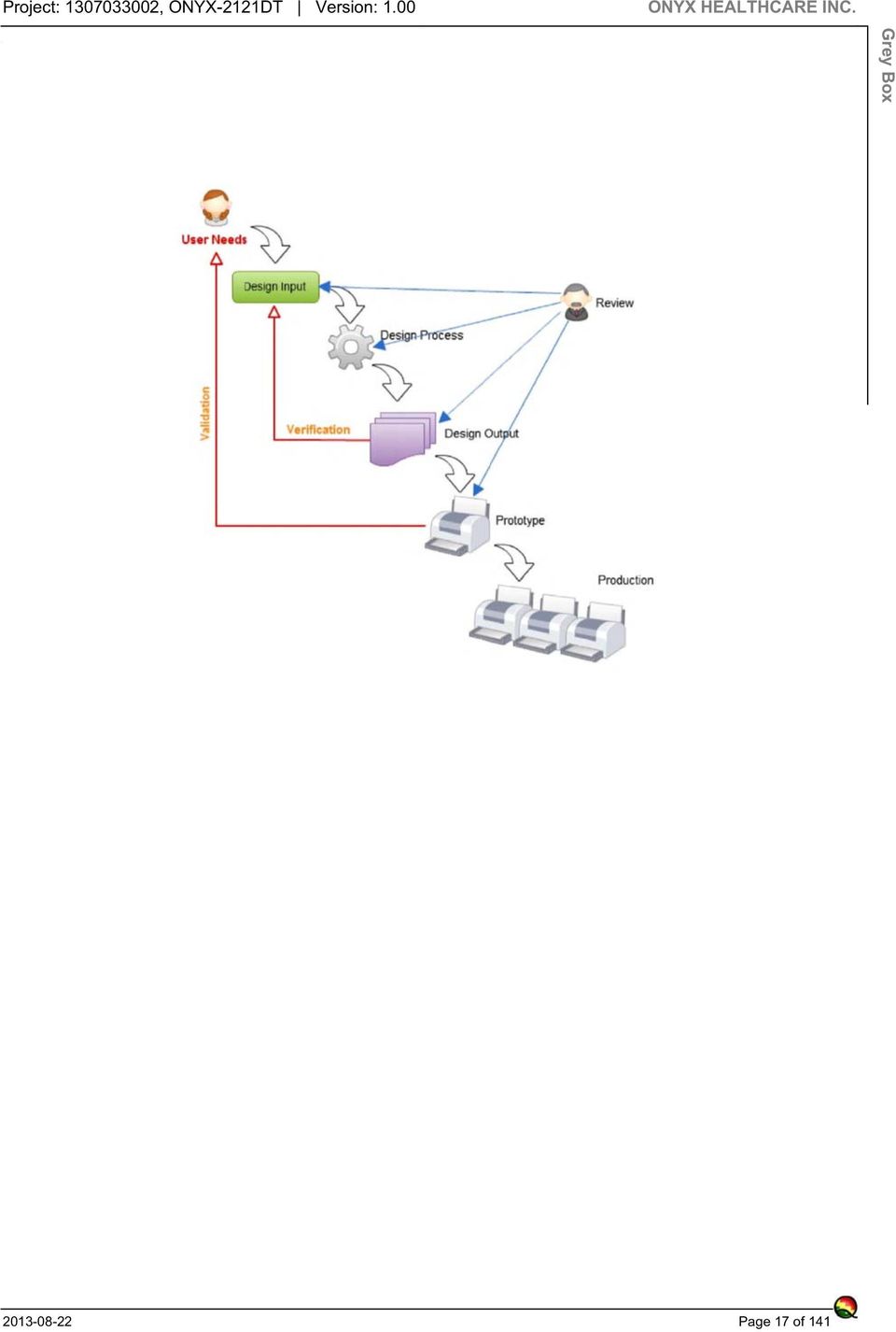
17 Grey Box Page 17 of 141
18 Risk Analysis Project: , ONYX-2121DT Version: 1.00 Risk Analysis Function: F-01 Connect to Mains Hazard Cause Effect on Measure Page 18 of 141

19 Hazard Cause H-01 Electromagnetic energy C-01 Short circuit of any or all insulation that does not comply with the requirements of IEC , 3rd Ed., Clause. 8.8 C-02 Short circuit of any or all CREEPAGE DISTANCES or AIR CLEARANCES that do not comply with the requirements of IEC , 3rd Ed., Clause 8.9 C-03 Open circuit of any or all earth connections that do not comply with the requirements of IEC , Clause 8.6, including any functional earth connection. C-04 Short circuit of any one insulation that complies with the requirements for one MEANS OF PROTECTION as specified in IEC , Clause 8.8 C-05 Short circuit of any one CREEPAGE DISTANCE or AIR CLEARANCE that complies with the requirements for one MEANS OF PROTECTION as specified in IEC , Clause 8.9 Effect on Measure M-01 The limits specified in IEC , Clause 8.4 is not be exceeded for ACCESSIBLE PARTS Risk Analysis M-01 The limits specified in IEC , Clause 8.4 is not be exceeded for ACCESSIBLE PARTS M-01 The limits specified in IEC , Clause 8.4 is not be exceeded for ACCESSIBLE PARTS M-01 The HAZARDOUS SITUATIONS in IEC , Clause to (inclusive) do not occur in the PC and power adapter. M-01 The HAZARDOUS SITUATIONS in IEC , Clause to (inclusive) do not occur in the PC and power adapter Page 19 of 141

20 Hazard Cause C-06 Open circuit of any one PROTECTIVE EARTH CONDUCTOR or internal PROTECTIVE EARTH CONNECTION that complies with the requirements of IEC , Clause 8.6 C-07 All components, including wiring, the failure of which could result in a HAZARDOUS SITUATION. C-08 The reliability of components that are used as MEANS OF PROTECTION are not assessed for the conditions of use in the PC. C-09 Storage (humidity preconditioning treatment) Effect on Measure M-01 The HAZARDOUS SITUATIONS in IEC , Clause to (inclusive) do not occur in the PC and power adapter. M-01 All components, including wiring shall be used in accordance with their specified ratings. M-02 All components, including wiring, the failure of which could result in a HAZARDOUS SITUATION are fixed in place by UL R/C nonchemical bonding compound. M-01 They shall comply with the applicable safety requirements of a relevant IEC, UL or ISO standard; M-02 Where there is no relevant IEC or ISO standard, the requirements of IEC , 3rd Ed. were applied. M-01 The humidity preconditioning treatment is performed in a humidity cabinet containing air with a relative humidity of 93 % ± 3 25 C 48 hr C-10 Transport M-01 The strength of packing carton / fixed frame. The transportation stimulation for the verification. All connections were mechanically secure. C-11 Components of PC, unwanted movement of which could result in an unacceptableb RISK, is not mounted securely to prevent such movement. C-12 Too high leakage current, causing a death or serious injury to a patient. M-01 Said components were secured in place on pcb by UL Recognized non-chemical bonding compound. M-01 Meet IEC , Clause 8.7 LEAKAGE CURRENTS and PATIENT AUXILIARY CURRENTS requirements Risk Analysis Page 20 of 141
 Effect on Measure M-01 The HAZARDOUS SITUATIONS in IEC 60601-1, Clause 13.1.2 to 13.1.4 (inclusive) do not occur in the PC and power adapter.")
21 Hazard Cause C-13 The LEAKAGE CURRENTS from, to or between ACCESSIBLE PARTS other than PATIENT CONNECTIONS C-14 ACCESSIBLE PARTS exceed 42.4 V peak a.c. or 60 V d.c. in NORMAL CONDITION or in SINGLE FAULT CONDITION. C-15 Internal parts, other than contacts of plugs, connectors and socketoutlets, that can be touched by the test pin shown in IEC , Figure 8. C-16 Accidental detachment of conductors and connectors where breaking free could lead to a HAZARDOUS SITUATION C-17 The resistance to heat is not retained by all types of insulation, including insulating partition walls, during the EXPECTED SERVICE LIFE of the PC. C-18 Internal cables and wiring is not adequately protected against contact with a moving part or Effect on Measure M-01 Meet IEC , Clause 8.7 LEAKAGE CURRENTS and PATIENT AUXILIARY CURRENTS requirements Risk Analysis M-01 Supplied by SELV power adapter and DC/AC inverter meet LCC requirements. M-01 The suitable enclosure shall be provided. M-01 The HAZARDOUS SITUATIONS in IEC , Clause to (inclusive) do not occur in the PC and power adapter. M-01 Shall compliance with the following tests: resistance to moisture, etc. (see IEC , Clause 11.6); dielectric strength (see IEC , Clause 8.8.3); and mechanical strength (see IEC , Clause 15.3). M-02 Ball pressure test - according to IEC , Clause , b) requirements M-01 Internal cables and wiring is fixed in place by cable tie to protect against contact with a moving part or from friction at sharp corners and edges where damage to insulation Page 21 of 141
22 Hazard Cause from friction at sharp corners and edges where damage to insulation. C-19 Electromagnetic compatibility of PC. Effect on Measure M-01 Meet IEC requirements C-20 Packing M-01 The permissible environmental conditions for transport and storage were marked on the outside of the packaging. C-21 Wirings and connectors of Panel PC Monitor supply is not secured or insulated that accidental detachment can result in a HAZARDOUS SITUATION. C-22 Internal cables and wiring were not adequately protected against contact from friction at sharp corners and edges where damage to insulation could result in a HAZARDOUS SITUATION. H-02 Thermal Energy C-01 Excessive temperatures in PC and/or power supply. M-01 All wirings are tied together by cable tie to prevent accidental detachment M-01 The internal wirings were secured in place on PCB by UL R/C nonchemical bonding component. C-23 Cleaning M-01 The equipment complied with the requirements of IEC , Clause C-02 ENCLOSURES have no the strength and rigidity necessary to avoid a fire. M-01 When PC is operated in worst-case NORMAL USE including the maximum ambient operating temperature, the parts shall not reach temperatures exceeding the values given in IEC , Table 22 and Table 23. M-01 Compliance with the mechanical strength tests for ENCLOSURES (see IEC , Clause 15.3) Risk Analysis Page 22 of 141
23 Function: F-02 Enclosure Hazard Cause Effect on Measure H-01 Mechanical energy C-01 Falling M-01 Meet IEC , Clause requirements. Risk Analysis C-02 Suspended masses M-01 Meet IEC Clause and Table 21 requirements. C-03 Sharp edges and corners M-01 Rounding of sharp edges and corners. H-02 Thermal Energy C-01 Excessive temperatures in enclosure M-01 When PC is operated in worst-case NORMAL USE including the maximum ambient operating temperature, the parts shall not reach temperatures exceeding the values given in IEC , Table 22 and Table 23. Function: F-03 Rear Bracket Hazard Cause Effect on Measure H-01 Mechanical energy C-01 Crack M-01 Meet IEC Clause and Table 21 requirements. C-02 Suspended masses M-01 Meet IEC Clause and Table 21 requirements. C-03 Instability M-01 Meet IEC , Clause requirements. Function: F-04 Signal input Hazard Cause H-01 Electromagnetic energy C-01 ACCESSIBLE PARTS exceed 42.4 V peak a.c. or 60 V d.c. in NORMAL CONDITION or in SINGLE FAULT CONDITION. Effect on Measure M-01 Supplied by SELV power adapter and DC/AC inverter meet LCC requirements Page 23 of 141
24 Function: F-05 Signal output Hazard Cause Effect on Measure H-01 Acoustic energy (sound) C-01 earphone M-01 Meet IEC , Annex NAD Acoustic tests requirements Risk Analysis Function: F-06 User control and indicator Hazard Cause H-01 Operational C-01 Switches used to control power to PC or its parts, including switches, did not have their "on" and "off" positions Effect on Measure M-01 Indicated by an adjacent indicator light M-02 Marked with symbols IEC Function: F-07 Information Hazard Cause H-01 Labeling C-01 PC did not marke with the name or trademark of Onyx and with a MODEL OR TYPE REFERENCE C-02 Incomplete instructions for use C-03 Inadequate description of performance characteristics C-04 Inadequate specification of intended use. C-05 Inadequate disclosure of limitations Effect on Measure M-01 PC marked the name or trademark of Onyx with model no. M-01 Meet IEC , Clause 7 requirements. M-01 Meet IEC , Clause 7 requirements. M-01 Meet IEC , Clause 7 requirements. M-01 Meet IEC , Clause 7 requirements Page 24 of 141
25 Hazard Cause H-02 Operating instructions C-01 Inadequate specification of accessories to be used with the medical device. Effect on Measure M-01 Meet IEC , Clause 7 requirements. Risk Analysis C-02 Inadequate specification of pre-use checks. M-01 Meet IEC , Clause 7 requirements. C-03 Over-complicated operating instructions M-01 Meet IEC , Clause 7 requirements. H-03 Specification of service and maintenance C-01 Installation instruction M-01 Meet IEC , Clause 7 requirements. Function: F-08 Connection to an external d.c. power source Hazard Cause H-01 Thermal Energy C-01 When a connection with the wrong polarity is made Effect on Measure M-01 Provided a connector that has special housing to prevent a connection with the wrong polarity is made Function: F-09 Display Hazard Cause Effect on Measure H-01 Radiation energy C-01 Visible Light M-01 The intensity of visible light from monitor can be controlled by the user. The highest intensity achievable cannot produce detrimental biological effects. Function: F-10 BIOS (Basic Input/Output System - real time clock) Hazard Cause Effect on Measure H-01 Mechanical energy C-01 Lithium battery explosion M-01 Battery circuits is designed so that discharging at a rate exceeding the battery manufacturer s recommendations, and unintentional charging, are prevented Page 25 of 141
26 Risk Evaluation Before Measures Project: , ONYX-2121DT Version: 1.00 Function: F-01 Connect to Mains Hazard Cause Severity Probability Region of Risk Comment Risk Evaluation Before Measures Page 26 of 141
27 Hazard Cause H-01 Electromagnetic energy C-01 Short circuit of any or all insulation that does not comply with the requirements of IEC , 3rd Ed., Clause. 8.8 C-02 Short circuit of any or all CREEPAGE DISTANCES or AIR CLEARANCES that do not comply with the requirements of IEC , 3rd Ed., Clause 8.9 C-03 Open circuit of any or all earth connections that do not comply with the requirements of IEC , Clause 8.6, including any functional earth connection. C-04 Short circuit of any one insulation that complies with the requirements for one MEANS OF PROTECTION as specified in IEC , Clause 8.8 C-05 Short circuit of any one CREEPAGE DISTANCE or AIR CLEARANCE that complies with the requirements for one MEANS OF PROTECTION as specified in IEC , Clause 8.9 C-06 Open circuit of any one PROTECTIVE EARTH CONDUCTOR or internal PROTECTIVE EARTH CONNECTION that complies with the requirements of IEC , Clause 8.6 C-07 All components, including wiring, the failure of which could result in a HAZARDOUS SITUATION. C-08 The reliability of components that are used as MEANS OF PROTECTION are not assessed for the conditions of use in the PC. C-09 Storage (humidity preconditioning treatment) Severity Probability Region of Risk Serious Occasional Inacceptable Serious Occasional Inacceptable Serious Occasional Inacceptable Critical Occasional Inacceptable Critical Remote Inacceptable Critical Occasional Inacceptable Serious Remote Acceptable Critical Remote Inacceptable Serious Occasional Inacceptable Comment Risk Evaluation Before Measures Page 27 of 141
28 Hazard Cause Severity Probability Region of Risk C-10 Transport Serious Remote Acceptable C-11 Components of PC, unwanted movement of which could result in an unacceptableb RISK, is not mounted securely to prevent such movement. C-12 Too high leakage current, causing a death or serious injury to a patient. C-13 The LEAKAGE CURRENTS from, to or between ACCESSIBLE PARTS other than PATIENT CONNECTIONS C-14 ACCESSIBLE PARTS exceed 42.4 V peak a.c. or 60 V d.c. in NORMAL CONDITION or in SINGLE FAULT CONDITION. C-15 Internal parts, other than contacts of plugs, connectors and socket-outlets, that can be touched by the test pin shown in IEC , Figure 8. Serious Remote Acceptable Critical Occasional Inacceptable Critical Occasional Inacceptable Critical Occasional Inacceptable Serious Remote Acceptable Comment Risk Evaluation Before Measures C-16 Accidental detachment of conductors and connectors where breaking free could lead to a HAZARDOUS SITUATION Serious Occasional Inacceptable C-17 The resistance to heat is not retained by all types of insulation, including insulating partition walls, during the EXPECTED SERVICE LIFE of the PC. Serious Occasional Inacceptable C-18 Internal cables and wiring is not adequately protected against contact with a moving part or from friction at sharp corners and edges where damage to insulation. Serious Occasional Inacceptable C-19 Electromagnetic compatibility of PC. Critical Occasional Inacceptable C-20 Packing Serious Occasional Inacceptable Page 28 of 141
29 Hazard Cause C-21 Wirings and connectors of Panel PC Monitor supply is not secured or insulated that accidental detachment can result in a HAZARDOUS SITUATION. C-22 Internal cables and wiring were not adequately protected against contact from friction at sharp corners and edges where damage to insulation could result in a HAZARDOUS SITUATION. Severity Probability Region of Risk Serious Remote Acceptable Serious Remote Acceptable C-23 Cleaning Minor Remote Acceptable H-02 Thermal Energy C-01 Excessive temperatures in PC and/or power supply. C-02 ENCLOSURES have no the strength and rigidity necessary to avoid a fire. Serious Occasional Inacceptable Critical Remote Inacceptable Comment Risk Evaluation Before Measures Function: F-02 Enclosure Hazard Cause Severity Probability Region of Risk H-01 Mechanical energy C-01 Falling Serious Occasional Inacceptable C-02 Suspended masses Serious Occasional Inacceptable C-03 Sharp edges and corners Minor Probable Inacceptable H-02 Thermal Energy C-01 Excessive temperatures in enclosure Serious Occasional Inacceptable Comment Page 29 of 141
30 Function: F-03 Rear Bracket Hazard Cause Severity Probability Region of Risk H-01 Mechanical energy C-01 Crack Serious Occasional Inacceptable C-02 Suspended masses Serious Remote Acceptable C-03 Instability Serious Occasional Inacceptable Comment Risk Evaluation Before Measures Function: F-04 Signal input Hazard Cause H-01 Electromagnetic energy C-01 ACCESSIBLE PARTS exceed 42.4 V peak a.c. or 60 V d.c. in NORMAL CONDITION or in SINGLE FAULT CONDITION. Severity Probability Region of Risk Critical Remote Inacceptable Comment Function: F-05 Signal output Hazard Cause Severity Probability Region of Risk H-01 Acoustic energy (sound) C-01 earphone Serious Occasional Inacceptable Comment Function: F-06 User control and indicator Hazard Cause H-01 Operational C-01 Switches used to control power to PC or its parts, including switches, did not have their "on" and "off" positions Severity Probability Region of Risk Serious Occasional Inacceptable Comment Page 30 of 141
31 Function: F-07 Information Hazard Cause H-01 Labeling C-01 PC did not marke with the name or trademark of Onyx and with a MODEL OR TYPE REFERENCE Severity Probability Region of Risk Minor Occasional Acceptable C-02 Incomplete instructions for use Critical Occasional Inacceptable C-03 Inadequate description of performance characteristics Serious Occasional Inacceptable C-04 Inadequate specification of intended use. Critical Occasional Inacceptable C-05 Inadequate disclosure of limitations Critical Occasional Inacceptable H-02 Operating instructions C-01 Inadequate specification of accessories to be used with the medical device. C-02 Inadequate specification of pre-use checks. H-03 Specification of service and maintenance Serious Remote Acceptable Minor Occasional Acceptable C-03 Over-complicated operating instructions Minor Occasional Acceptable C-01 Installation instruction Serious Occasional Inacceptable Comment Risk Evaluation Before Measures Function: F-08 Connection to an external d.c. power source Hazard Cause H-01 Thermal Energy C-01 When a connection with the wrong polarity is made Severity Probability Region of Risk Serious Occasional Inacceptable Comment Page 31 of 141
32 Function: F-09 Display Hazard Cause Severity Probability Region of Risk H-01 Radiation energy C-01 Visible Light Minor Occasional Acceptable Function: F-10 BIOS (Basic Input/Output System - real time clock) Hazard Cause Severity Probability Region of Risk H-01 Mechanical energy C-01 Lithium battery explosion Critical Occasional Inacceptable Comment Comment Risk Evaluation Before Measures Page 32 of 141
33 Risk Graph Before Measures Project: , ONYX-2121DT Version: 1.00 Both Conditions Operating Condition Risk Graph Before Measures Failure Mode Acceptable ALARP Inacceptable Page 33 of 141
34 Decision about Measures Project: , ONYX-2121DT Version: 1.00 Measure: RC-001 All components, including wiring shall be used in accordance with their specified ratings. Implement: Decision about Measures Function Hazard Cause Effectiveness Assessment of the Measure Connect to Mains Electromagnetic energy All components, including wiring, the failure of which could result in a HAZARDOUS SITUATION. Effective Measure: RC-002 All components, including wiring, the failure of which could result in a HAZARDOUS SITUATION are fixed in place by UL R/C non-chemical bonding compound. Implement: Function Hazard Cause Effectiveness Assessment of the Measure Connect to Mains Electromagnetic energy All components, including wiring, the failure of which could result in a HAZARDOUS SITUATION. Effective Measure: RC-003 All wirings are tied together by cable tie to prevent accidental detachment Implement: Page 34 of 141
35 Function Hazard Cause Effectiveness Assessment of the Measure Connect to Mains Electromagnetic energy Wirings and connectors of Panel PC Monitor supply is not secured or insulated that accidental detachment can result in a HAZARDOUS SITUATION. Effective Measure: RC-004 Ball pressure test - according to IEC , Clause , b) requirements Decision about Measures Implement: Function Hazard Cause Effectiveness Assessment of the Measure Connect to Mains Electromagnetic energy The resistance to heat is not retained by all types of insulation, including insulating partition walls, during the EXPECTED SERVICE LIFE of the PC. Effective Measure: RC-005 Battery circuits is designed so that discharging at a rate exceeding the battery manufacturer s recommendations, and unintentional charging, are prevented. Implement: Function Hazard Cause Effectiveness Assessment of the Measure BIOS (Basic Input/Output System Mechanical energy Lithium battery explosion Effective - real time clock) Page 35 of 141
36 Measure: RC-006 Compliance with the mechanical strength tests for ENCLOSURES (see IEC , Clause 15.3) Implement: Function Hazard Cause Effectiveness Assessment of the Measure Connect to Mains Thermal Energy ENCLOSURES have no the strength and rigidity necessary to avoid a fire. Effective Decision about Measures Measure: RC-007 Indicated by an adjacent indicator light Implement: Function Hazard Cause Effectiveness Assessment of the Measure User control and indicator Operational Switches used to control power to PC or its parts, including switches, did not have their "on" and "off" positions Effective Measure: RC-008 Internal cables and wiring is fixed in place by cable tie to protect against contact with a moving part or from friction at sharp corners and edges where damage to insulation Implement: Page 36 of 141
37 Function Hazard Cause Effectiveness Assessment of the Measure Connect to Mains Electromagnetic energy Internal cables and wiring is not adequately protected against contact with a moving part or from friction at sharp corners and edges where damage to insulation. Effective Measure: Marked with symbols IEC RC-009 Decision about Measures Implement: Function Hazard Cause Effectiveness Assessment of the Measure User control and indicator Operational Switches used to control power to PC or its parts, including switches, did not have their "on" and "off" positions Effective Measure: RC-010 Meet IEC Clause and Table 21 requirements. Implement: Function Hazard Cause Effectiveness Assessment of the Measure Enclosure Mechanical energy Suspended masses Effective Rear Bracket Mechanical energy Crack Effective Rear Bracket Mechanical energy Suspended masses Effective Page 37 of 141
38 Measure: RC-011 Meet IEC , Clause 7 requirements. Implement: Function Hazard Cause Effectiveness Assessment of the Measure Information Labeling Incomplete instructions for use Effective Information Labeling Inadequate description of performance characteristics Effective Information Labeling Inadequate specification of intended use. Effective Information Labeling Inadequate disclosure of limitations Effective Information Operating instructions Inadequate specification of accessories to be used with the medical device. Effective Information Operating instructions Inadequate specification of preuse checks. Effective Information Operating instructions Over-complicated operating instructions Effective Information Specification of service and maintenance Installation instruction Effective Decision about Measures Measure: RC-012 Meet IEC , Clause 8.7 LEAKAGE CURRENTS and PATIENT AUXILIARY CURRENTS requirements Implement: Function Hazard Cause Effectiveness Assessment of the Measure Connect to Mains Electromagnetic energy Too high leakage current, causing a death or serious injury to a patient. Effective Page 38 of 141
39 Function Hazard Cause Effectiveness Assessment of the Measure Connect to Mains Electromagnetic energy The LEAKAGE CURRENTS from, to or between ACCESSIBLE PARTS other than PATIENT CONNECTIONS Effective Measure: RC-013 Meet IEC , Clause requirements. Decision about Measures Implement: Function Hazard Cause Effectiveness Assessment of the Measure Enclosure Mechanical energy Falling Effective Rear Bracket Mechanical energy Instability Effective Measure: Meet IEC requirements RC-014 Implement: Function Hazard Cause Effectiveness Assessment of the Measure Connect to Mains Electromagnetic energy Electromagnetic compatibility of Effective PC. Measure: RC-015 Meet IEC , Annex NAD Acoustic tests requirements Implement: Page 39 of 141
40 Function Hazard Cause Effectiveness Assessment of the Measure Signal output Acoustic energy (sound) earphone Effective Measure: RC-016 PC marked the name or trademark of Onyx with model no. Implement: Decision about Measures Function Hazard Cause Effectiveness Assessment of the Measure Information Labeling PC did not marke with the name or trademark of Onyx and with a MODEL OR TYPE REFERENCE Effective Measure: RC-017 Provided a connector that has special housing to prevent a connection with the wrong polarity is made Implement: Function Hazard Cause Effectiveness Assessment of the Measure Connection to an external d.c. Thermal Energy When a connection with the wrong Effective power source polarity is made Measure: RC-018 Rounding of sharp edges and corners. Implement: Page 40 of 141
41 Function Hazard Cause Effectiveness Assessment of the Measure Enclosure Mechanical energy Sharp edges and corners Effective Measure: RC-019 Said components were secured in place on pcb by UL Recognized non-chemical bonding compound. Implement: Decision about Measures Function Hazard Cause Effectiveness Assessment of the Measure Connect to Mains Electromagnetic energy Components of PC, unwanted movement of which could result in an unacceptableb RISK, is not mounted securely to prevent such movement. Effective Measure: RC-020 Shall compliance with the following tests: resistance to moisture, etc. (see IEC , Clause 11.6); dielectric strength (see IEC , Clause 8.8.3); and mechanical strength (see IEC , Clause 15.3). Implement: Function Hazard Cause Effectiveness Assessment of the Measure Connect to Mains Electromagnetic energy The resistance to heat is not retained by all types of insulation, including insulating partition walls, during the EXPECTED SERVICE LIFE of the PC. Effective Page 41 of 141
42 Measure: RC-021 Supplied by SELV power adapter and DC/AC inverter meet LCC requirements. Implement: Function Hazard Cause Effectiveness Assessment of the Measure Connect to Mains Electromagnetic energy ACCESSIBLE PARTS exceed 42.4 V peak a.c. or 60 V d.c. in NORMAL CONDITION or in SINGLE FAULT CONDITION. Effective Signal input Electromagnetic energy ACCESSIBLE PARTS exceed 42.4 V peak a.c. or 60 V d.c. in NORMAL CONDITION or in SINGLE FAULT CONDITION. Effective Decision about Measures Measure: RC-022 The equipment complied with the requirements of IEC , Clause Implement: Function Hazard Cause Effectiveness Assessment of the Measure Connect to Mains Electromagnetic energy Cleaning Effective Measure: RC-023 The HAZARDOUS SITUATIONS in IEC , Clause to (inclusive) do not occur in the PC and power adapter. Implement: Page 42 of 141
43 Function Hazard Cause Effectiveness Assessment of the Measure Connect to Mains Electromagnetic energy Short circuit of any one insulation that complies with the requirements for one MEANS OF PROTECTION as specified in IEC , Clause 8.8 Effective Connect to Mains Electromagnetic energy Short circuit of any one CREEPAGE DISTANCE or AIR CLEARANCE that complies with the requirements for one MEANS OF PROTECTION as specified in IEC , Clause 8.9 Effective Connect to Mains Electromagnetic energy Open circuit of any one PROTECTIVE EARTH CONDUCTOR or internal PROTECTIVE EARTH CONNECTION that complies with the requirements of IEC , Clause 8.6 Effective Connect to Mains Electromagnetic energy Accidental detachment of conductors and connectors where breaking free could lead to a HAZARDOUS SITUATION Effective Decision about Measures Measure: RC-024 The humidity preconditioning treatment is performed in a humidity cabinet containing air with a relative humidity of 93 % ± 3 25 C 48 hr Implement: Function Hazard Cause Effectiveness Assessment of the Measure Connect to Mains Electromagnetic energy Storage (humidity preconditioning Effective treatment) Page 43 of 141
44 Measure: RC-025 The intensity of visible light from monitor can be controlled by the user. The highest intensity achievable cannot produce detrimental biological effects. Implement: Function Hazard Cause Effectiveness Assessment of the Measure Display Radiation energy Visible Light Effective Decision about Measures Measure: RC-026 The internal wirings were secured in place on PCB by UL R/C non-chemical bonding component. Implement: Function Hazard Cause Effectiveness Assessment of the Measure Connect to Mains Electromagnetic energy Internal cables and wiring were not adequately protected against contact from friction at sharp corners and edges where damage to insulation could result in a HAZARDOUS SITUATION. Effective Measure: RC-027 The limits specified in IEC , Clause 8.4 is not be exceeded for ACCESSIBLE PARTS Implement: Function Hazard Cause Effectiveness Assessment of the Measure Connect to Mains Electromagnetic energy Short circuit of any or all insulation that does not comply with the requirements of IEC , 3rd Ed., Clause. 8.8 Effective Page 44 of 141
45 Function Hazard Cause Effectiveness Assessment of the Measure Connect to Mains Electromagnetic energy Short circuit of any or all CREEPAGE DISTANCES or AIR CLEARANCES that do not comply with the requirements of IEC , 3rd Ed., Clause 8.9 Effective Connect to Mains Electromagnetic energy Open circuit of any or all earth connections that do not comply with the requirements of IEC , Clause 8.6, including any functional earth connection. Effective Decision about Measures Measure: RC-028 The permissible environmental conditions for transport and storage were marked on the outside of the packaging. Implement: Function Hazard Cause Effectiveness Assessment of the Measure Connect to Mains Electromagnetic energy Packing Effective Measure: RC-029 The strength of packing carton / fixed frame. The transportation stimulation for the verification. All connections were mechanically secure. Implement: Function Hazard Cause Effectiveness Assessment of the Measure Connect to Mains Electromagnetic energy Transport Effective Page 45 of 141
46 Measure: RC-030 The suitable enclosure shall be provided. Implement: Function Hazard Cause Effectiveness Assessment of the Measure Connect to Mains Electromagnetic energy Internal parts, other than contacts of plugs, connectors and socketoutlets, that can be touched by the test pin shown in IEC , Figure 8. Effective Decision about Measures Measure: RC-031 They shall comply with the applicable safety requirements of a relevant IEC, UL or ISO standard; Implement: Function Hazard Cause Effectiveness Assessment of the Measure Connect to Mains Electromagnetic energy The reliability of components that are used as MEANS OF PROTECTION are not assessed for the conditions of use in the PC. Effective Measure: RC-032 When PC is operated in worst-case NORMAL USE including the maximum ambient operating temperature, the parts shall not reach temperatures exceeding the values given in IEC , Table 22 and Table 23. Implement: Function Hazard Cause Effectiveness Assessment of the Measure Connect to Mains Thermal Energy Excessive temperatures in PC Effective and/or power supply Page 46 of 141
47 Function Hazard Cause Effectiveness Assessment of the Measure Enclosure Thermal Energy Excessive temperatures in Effective enclosure Measure: RC-033 Where there is no relevant IEC or ISO standard, the requirements of IEC , 3rd Ed. were applied. Decision about Measures Implement: Function Hazard Cause Effectiveness Assessment of the Measure Connect to Mains Electromagnetic energy The reliability of components that are used as MEANS OF PROTECTION are not assessed for the conditions of use in the PC. Effective Page 47 of 141
48 Risk Control Project: , ONYX-2121DT Version: 1.00 Risk Control No. Measure RC-001 All components, including wiring shall be used in accordance with their specified ratings. RC-002 All components, including wiring, the failure of which could result in a HAZARDOUS SITUATION are fixed in place by UL R/C nonchemical bonding compound. RC-003 All wirings are tied together by cable tie to prevent accidental detachment RC-004 Ball pressure test - according to IEC , Clause , b) requirements RC-005 Battery circuits is designed so that discharging at a rate exceeding the battery manufacturer s recommendations, and unintentional charging, are prevented. State of Work Validation Responsible Implementation Planning Actual Values Effort Supervision Begin End Begin End Planned Is Release Completed Yuan, Andy Chen, Ernest 5/1/2013 8/31/2013 5/2/2013 6/18/2013 Yes Yes Completed Yuan, Andy Chen, Ernest 5/1/2013 8/31/2013 5/3/2013 7/17/2013 Yes Yes Completed Chen, Ernest Yuan, Andy 5/1/2013 8/31/2013 5/12/2013 7/5/2013 Yes Yes Completed Chen, Ernest Yuan, Andy 5/1/2013 8/31/2013 5/6/2013 6/28/2013 Yes Yes Completed Yuan, Andy Lin, Eason 5/1/2013 8/31/2013 5/8/2013 6/18/2013 Yes Yes Page 48 of 141
49 No. Measure RC-006 Compliance with the mechanical strength tests for ENCLOSURES (see IEC , Clause 15.3) RC-007 Indicated by an adjacent indicator light RC-008 Internal cables and wiring is fixed in place by cable tie to protect against contact with a moving part or from friction at sharp corners and edges where damage to insulation RC-009 Marked with symbols IEC RC-010 Meet IEC Clause and Table 21 requirements. RC-011 Meet IEC , Clause 7 requirements. RC-012 Meet IEC , Clause 8.7 LEAKAGE CURRENTS and PATIENT AUXILIARY CURRENTS requirements RC-013 Meet IEC , Clause requirements. State of Work Validation Responsible Implementation Planning Actual Values Effort Supervision Begin End Begin End Planned Is Release Completed Chen, Ernest Yuan, Andy 5/1/2013 8/31/2013 5/13/2013 6/25/2013 Yes Yes Completed Chen, Ernest Yuan, Andy 5/1/2013 8/31/2013 5/14/2013 6/18/2013 Yes Yes Completed Chen, Ernest Yuan, Andy 5/1/2013 8/31/2013 5/3/2013 6/20/2013 Yes Yes Completed Chen, Ernest Yuan, Andy 5/1/2013 8/31/2013 5/2/2013 6/25/2013 Yes Yes Completed Chen, Ernest Yuan, Andy 5/1/2013 8/31/2013 5/8/2013 7/5/2013 Yes Yes Completed Lin, Eason Chen, Ernest 5/1/2013 8/31/2013 5/6/2013 7/5/2013 Yes Yes Completed Yuan, Andy Chen, Ernest 5/1/2013 8/31/2013 5/6/2013 7/15/2013 Yes Yes Completed Chen, Ernest Yuan, Andy 5/1/2013 8/31/2013 5/9/2013 6/27/2013 Yes Yes Risk Control Page 49 of 141
50 No. Measure RC-014 Meet IEC requirements RC-015 Meet IEC , Annex NAD Acoustic tests requirements RC-016 PC marked the name or trademark of Onyx with model no. RC-017 Provided a connector that has special housing to prevent a connection with the wrong polarity is made RC-018 Rounding of sharp edges and corners. RC-019 Said components were secured in place on pcb by UL Recognized nonchemical bonding compound. RC-020 Shall compliance with the following tests: resistance to moisture, etc. (see IEC , Clause 11.6); dielectric strength (see IEC , Clause 8.8.3); and mechanical strength (see IEC , Clause 15.3). State of Work Validation Responsible Implementation Planning Actual Values Effort Supervision Begin End Begin End Planned Is Release Completed Yuan, Andy Lin, Eason 5/1/2013 8/31/2013 5/10/2013 6/19/2013 Yes Yes Completed Yuan, Andy Chen, Ernest 5/1/2013 8/31/2013 5/3/2013 7/8/2013 Yes Yes Completed Lin, Eason Chen, Ernest 5/1/2013 8/31/2013 5/8/2013 6/21/2013 Yes Yes Completed Chen, Ernest Yuan, Andy 5/1/2013 8/31/2013 5/7/2013 6/25/2013 Yes Yes Completed Chen, Ernest Yuan, Andy 5/1/2013 8/31/2013 5/13/2013 6/25/2013 Yes Yes Completed Chen, Ernest Yuan, Andy 5/1/2013 8/31/2013 5/24/2013 6/28/2013 Yes Yes Completed Yuan, Andy Chen, Ernest 5/1/2013 8/31/2013 5/17/2013 7/8/2013 Yes Yes Risk Control Page 50 of 141
51 No. Measure RC-021 Supplied by SELV power adapter and DC/AC inverter meet LCC requirements. RC-022 The equipment complied with the requirements of IEC , Clause RC-023 The HAZARDOUS SITUATIONS in IEC , Clause to (inclusive) do not occur in the PC and power adapter. RC-024 The humidity preconditioning treatment is performed in a humidity cabinet containing air with a relative humidity of 93 % ± 3 25 C 48 hr RC-025 The intensity of visible light from monitor can be controlled by the user. The highest intensity achievable cannot produce detrimental biological effects. RC-026 The internal wirings were secured in place on PCB by UL R/C non-chemical bonding component. State of Work Validation Responsible Implementation Planning Actual Values Effort Supervision Begin End Begin End Planned Is Release Completed Yuan, Andy Chen, Ernest 5/1/2013 8/31/2013 5/5/2013 7/22/2013 Yes Yes Completed Yuan, Andy Chen, Ernest 5/1/2013 8/31/2013 5/7/2013 7/11/2013 Yes Yes Completed Yuan, Andy Chen, Ernest 5/1/2013 8/31/2013 5/3/2013 6/28/2013 Yes Yes Completed Chen, Ernest Yuan, Andy 5/1/2013 8/31/2013 5/8/2013 6/26/2013 Yes Yes Completed Chen, Ernest Yuan, Andy 5/1/2013 8/31/2013 5/7/2013 7/4/2013 Yes Yes Completed Chen, Ernest Yuan, Andy 5/1/2013 8/31/2013 5/8/2013 6/25/2013 Yes Yes Risk Control Page 51 of 141
52 No. Measure RC-027 The limits specified in IEC , Clause 8.4 is not be exceeded for ACCESSIBLE PARTS RC-028 The permissible environmental conditions for transport and storage were marked on the outside of the packaging. RC-029 The strength of packing carton / fixed frame. The transportation stimulation for the verification. All connections were mechanically secure. RC-030 The suitable enclosure shall be provided. RC-031 They shall comply with the applicable safety requirements of a relevant IEC, UL or ISO standard; RC-032 When PC is operated in worst-case NORMAL USE including the maximum ambient operating temperature, the parts shall not reach temperatures exceeding the values given in IEC , Table 22 and Table 23. State of Work Validation Responsible Implementation Planning Actual Values Effort Supervision Begin End Begin End Planned Is Release Completed Yuan, Andy Lin, Eason 5/1/2013 8/31/2013 5/8/2013 7/9/2013 Yes Yes Completed Chen, Ernest Lin, Eason 5/1/2013 8/31/2013 5/8/2013 7/18/2013 Yes Yes Completed Chen, Ernest Lin, Eason 5/1/2013 8/31/2013 5/9/2013 7/15/2013 Yes Yes Completed Chen, Ernest Lin, Eason 5/1/2013 8/31/2013 5/2/2013 7/2/2013 Yes Yes Completed Yuan, Andy Chen, Ernest 5/1/2013 8/31/2013 5/8/2013 7/12/2013 Yes Yes Completed Yuan, Andy Chen, Ernest 5/1/2013 8/31/2013 5/7/2013 7/10/2013 Yes Yes Risk Control Page 52 of 141
53 No. Measure RC-033 Where there is no relevant IEC or ISO standard, the requirements of IEC , 3rd Ed. were applied. State of Work Validation Responsible Implementation Planning Actual Values Effort Supervision Begin End Begin End Planned Is Release Completed Lin, Mac Yuan, Andy 5/1/2013 8/31/2013 5/6/2013 6/27/2013 Yes Yes Risk Control Page 53 of 141
54 Release Protocol of Measures Project: , ONYX-2121DT Version: 1.00 Measure Number: Measure Text: Measure Status: RC-001 All components, including wiring shall be used in accordance with their specified ratings. Completed Release Protocol of Measures Responsible: Implementation: Yuan, Andy Supervision: Chen, Ernest Planning: Begin: 5/1/2013 End: 8/31/2013 Actual Values: Begin: 5/2/2013 End: 6/18/2013 Effort: planned: Is: Validation: Validated: Validated by: Chen, James Validated on: 7/19/2013 Release: Released: Released by: Lin, Mac Release on: 7/19/2013 Decided Individual Measures: Comment: All components, including wiring shall be used in accordance with their specified ratings. Where safety is involved, components shall comply either with the requirements of IEC or with the safety aspects of the relevant IEC component standards. Functions Hazards Causes Connect to Mains Electromagnetic energy All components, including wiring, the failure of which could result in a HAZARDOUS SITUATION. Implementation Team: Chen, James Lin, Mac Lin, Eason Chen, Ernest Yuan, Andy Page 54 of 141
55 Procedure for Evidence of Efficency of Measures: Evaluation and testing of components shall be conducted as follows: - a component that has been demonstrated to comply with a standard harmonized with the relevant IEC component standard shall be checked for correct application and use in accordance with its rating. It shall be subjected to the applicable tests of IEC as part of the equipment with the exception of those tests which are part of the relevant IEC component standard; - a component that has not been demonstrated to comply with a relevant standard as above shall be checked for correct application and use in accordance with its specified rating. It shall be subjected to the applicable tests of IEC , as part of the equipment, and to the applicable tests of the component standard, under the conditions occurring in the equipment; - where no relevant IEC component standard exists, or where components are used in circuits not in accordance with their specified ratings, the components shall be tested under the conditions occurring in the equipment. The number of samples required for test is, in general, the same as required by an equivalent standard. QD2-001, QD2-004, QD2-005 Release Protocol of Measures Limits of Acceptance for Procedure of Evidence: QD2-001, QD2-004, QD2-005 Procedure of Verification: QD2-001, QD2-004, QD2-005 Limits of Acceptance for Verification: QD2-001, QD2-004, QD2-005 Procedure of Validation: QD2-001, QD2-004, QD2-005 Limits of Acceptance for Validation: QD2-001, QD2-004, QD Page 55 of 141
56 Measure Number: Measure Text: Measure Status: RC-002 All components, including wiring, the failure of which could result in a HAZARDOUS SITUATION are fixed in place by UL R/C non-chemical bonding compound. Completed Responsible: Implementation: Yuan, Andy Supervision: Chen, Ernest Release Protocol of Measures Planning: Begin: 5/1/2013 End: 8/31/2013 Actual Values: Begin: 5/3/2013 End: 7/17/2013 Effort: planned: Is: Validation: Validated: Validated by: Chen, James Validated on: 7/19/2013 Release: Released: Released by: Lin, Mac Release on: 7/19/2013 Decided Individual Measures: Comment: All components, including wiring, the failure of which could result in a HAZARDOUS SITUATION are fixed in place by UL R/C non-chemical bonding compound. Conductors shall be provided with a means (for example, barriers or fixing), or be so terminated, that they and their terminators (for example, ring terminals and flat quick-connect terminals) cannot, in normal use, become so displaced that CLEARANCES or CREEPAGE DISTANCES are reduced to less than the values specified in IEC Functions Hazards Causes Connect to Mains Electromagnetic energy All components, including wiring, the failure of which could result in a HAZARDOUS SITUATION. Implementation Team: Chen, James Lin, Mac Lin, Eason Chen, Ernest Yuan, Andy Page 56 of 141
57 Procedure for Evidence of Efficency of Measures: Having used the unjointed probe, which was in the shape of the standard test finger and which incorporated a force gauge, a steady force of 10 N for internal parts was applied for a period of 5 seconds. QD2-001, QM2-011 Limits of Acceptance for Procedure of Evidence: During the application of the test force, clearances behind earthed or unearthed conductive accessable parts were not reduced to a level that would result in an energy hazard. QD2-001, QM2-011 Release Protocol of Measures Procedure of Verification: See above QD2-001, QM2-011 Limits of Acceptance for Verification: See above QD2-001, QM2-011 Procedure of Validation: See above QD2-001, QM2-011 Limits of Acceptance for Validation: See above QD2-001, QM Page 57 of 141
58 Measure Number: Measure Text: Measure Status: RC-003 All wirings are tied together by cable tie to prevent accidental detachment Completed Responsible: Implementation: Chen, Ernest Supervision: Yuan, Andy Planning: Begin: 5/1/2013 End: 8/31/2013 Release Protocol of Measures Actual Values: Begin: 5/12/2013 End: 7/5/2013 Effort: planned: Is: Validation: Validated: Validated by: Chen, James Validated on: 7/19/2013 Release: Released: Released by: Lin, Mac Release on: 7/19/2013 Decided Individual Measures: Comment: Tied together by cable tie. Conductors shall be provided with a means (for example, barriers or fixing), or be so terminated, that they and their terminators (for example, ring terminals and flat quick-connect terminals) cannot, in normal use, become so displaced that CLEARANCES or CREEPAGE DISTANCES are reduced to less than the values specified in IEC Functions Hazards Causes Connect to Mains Electromagnetic energy Wirings and connectors of Panel PC Monitor supply is not secured or insulated that accidental detachment can result in a HAZARDOUS SITUATION. Implementation Team: Chen, James Lin, Mac Lin, Eason Chen, Ernest Yuan, Andy Procedure for Evidence of Efficency of Measures: Having used the unjointed probe, which was in the shape of the standard test finger and which incorporated a force gauge, a steady force of 10 N for internal parts was applied for a period of 5 seconds. QD2-001, QM Page 58 of 141
59 Limits of Acceptance for Procedure of Evidence: During the application of the test force, clearances behind earthed or unearthed conductive accessible parts were not reduced to a level that would result in an energy hazard. QD2-001, QM2-011 Procedure of Verification: See above QD2-001, QM2-011 Release Protocol of Measures Limits of Acceptance for Verification: See above QD2-001, QM2-011 Procedure of Validation: See above QD2-001, QM2-011 Limits of Acceptance for Validation: See above QD2-001, QM Page 59 of 141
60 Measure Number: Measure Text: Measure Status: RC-004 Ball pressure test - according to IEC , Clause , b) requirements Completed Responsible: Implementation: Chen, Ernest Supervision: Yuan, Andy Planning: Begin: 5/1/2013 End: 8/31/2013 Release Protocol of Measures Actual Values: Begin: 5/6/2013 End: 6/28/2013 Effort: planned: Is: Validation: Validated: Validated by: Chen, James Validated on: 7/19/2013 Release: Released: Released by: Lin, Mac Release on: 7/19/2013 Decided Individual Measures: Comment: Compliance is checked by subjecting the part to the ballpressure test according to IEC and IEC , Clause , b) Thermoplastic parts on which parts at HAZARDOUS VOLTAGE are directly mounted shall be resistant to abnormal heat. Functions Hazards Causes Connect to Mains Electromagnetic energy The resistance to heat is not retained by all types of insulation, including insulating partition walls, during the EXPECTED SERVICE LIFE of the PC. Implementation Team: Chen, James Lin, Mac Lin, Eason Chen, Ernest Yuan, Andy Page 60 of 141
61 Procedure for Evidence of Efficency of Measures: A sample of each external part of insulating material indicated in the table was tested using the test apparatus shown in Fig. 21 of IEC , 3rd Edition. (In this apparatus, a steel ball of 5 mm diameter exerts a force of 20 N when pressed against a surface). The apparatus and a fire (or sand) brick were placed in an air-circulating oven. Once the apparatus and brick attained the oven temperature, the sample was placed in the oven on top of the brick. The steel ball was then positioned such that the apparatus was balanced on the surface of the sample. After 1 h, it was removed and the diameter of the impression made by the ball was measured. The specified oven temperature was the higher of the following: a. the sum of the specified ambient and the temperature rise of relevant part during the Temperature Test; AND b. 75 C ± 2 C (test per Clause a), OR 125 C ± 2 C (test per Clause b) IEC , 3rd Edition, Clause Release Protocol of Measures Limits of Acceptance for Procedure of Evidence: The results were less 2 mm. Cracks were not visible to the naked eye. IEC , 3rd Edition, Clause Procedure of Verification: IEC , 3rd Edition, Clause Limits of Acceptance for Verification: IEC , 3rd Edition, Clause Procedure of Validation: IEC , 3rd Edition, Clause Limits of Acceptance for Validation: IEC , 3rd Edition, Clause Page 61 of 141
62 Measure Number: Measure Text: Measure Status: RC-005 Battery circuits is designed so that discharging at a rate exceeding the battery manufacturer s recommendations, and unintentional charging, are prevented. Completed Responsible: Implementation: Yuan, Andy Supervision: Lin, Eason Release Protocol of Measures Planning: Begin: 5/1/2013 End: 8/31/2013 Actual Values: Begin: 5/8/2013 End: 6/18/2013 Effort: planned: Is: Validation: Validated: Validated by: Chen, James Validated on: 7/19/2013 Release: Released: Released by: Lin, Mac Release on: 7/19/2013 Decided Individual Measures: Comment: Battery circuits is designed so that discharging at a rate exceeding the battery manufacturer s recommendations, and unintentional charging, are prevented. Equipment containing batteries shall be designed to reduce the risk of fire, explosion and chemical leaks under normal conditions and after a single fault in the equipment, including a fault in circuitry within the equipment battery pack. Functions Hazards Causes BIOS (Basic Input/Output System - Mechanical energy Lithium battery explosion real time clock) Implementation Team: Chen, James Lin, Mac Lin, Eason Chen, Ernest Yuan, Andy Page 62 of 141
63 Procedure for Evidence of Efficency of Measures: The non-rechargeable battery cell was subjected to the test detailed below. The unit was connected to rated input voltage and operated at maximum normal load. The following conditions were imposed one at a time. 1) Unintentional charging of a non-rechargeable battery (pack or cell). The battery was charged while briefly subjected to the simulation of any single component failure that was likely to occur in the charging circuit and that would result in unintentional charging of the battery. To minimize testing time, the failure was chosen that causes the highest charging current. The battery was then charged for a single period of 7 h with that simulated failure in place. 2) Excessive discharging rate for any battery (pack or cell). The battery was subjected to rapid discharge by open-circuiting or short-circuiting any current-limiting or voltage-limiting components in the load circuit of the battery under test. 3) Reversing - The connections of the battery were reversed and the equipment was energized. The battery was examined for emission of flames, toxic gases, molten metal, risk of explosion. IEC , Clause and Release Protocol of Measures Limits of Acceptance for Procedure of Evidence: These tests shall not result in any of the following: - chemical leaks caused by cracking, rupturing or bursting of the battery jacket, if such leakage could adversely affect required insulation; or - spillage of liquid from any pressure relief device in the battery, unless such spillage is contained by the equipment without risk of damage to the insulation or harm to the USER; or - explosion of the battery, if such explosion could result in injury to a USER; or - emission of flame or expulsion of molten metal to the outside of the equipment ENCLOSURE. After completion of the tests, the equipment is subjected to the electric strength tests of IEC , Clause IEC , Clause and Procedure of Verification: IEC , Clause and Limits of Acceptance for Verification: IEC , Clause and Procedure of Validation: IEC , Clause and Limits of Acceptance for Validation: IEC , Clause and Page 63 of 141
64 Measure Number: Measure Text: Measure Status: RC-006 Compliance with the mechanical strength tests for ENCLOSURES (see IEC , Clause 15.3) Completed Responsible: Implementation: Chen, Ernest Supervision: Yuan, Andy Planning: Begin: 5/1/2013 End: 8/31/2013 Release Protocol of Measures Actual Values: Begin: 5/13/2013 End: 6/25/2013 Effort: planned: Is: Validation: Validated: Validated by: Chen, James Validated on: 7/19/2013 Release: Released: Released by: Lin, Mac Release on: 7/19/2013 Decided Individual Measures: Comment: The suitable plastic enclosure is provided. The PC or its parts shall have adequate mechanical strength and shall not result in an unacceptable RISK due to moulding stress or when subjected to mechanical stress caused by pushing, impact, dropping, and rough handling. Functions Hazards Causes Connect to Mains Thermal Energy ENCLOSURES have no the strength and rigidity necessary to avoid a fire. Implementation Team: Chen, James Lin, Mac Lin, Eason Chen, Ernest Yuan, Andy Procedure for Evidence of Efficency of Measures: Compliance is checked by application of the tests in Table 28. The tests are not applied to handles, levers, knobs, the face of cathode ray tubes (see 9.5.2), or to transparent or translucent covers of indicating or measuring devices unless with the handle, lever, knob, or cover removed there is an unacceptable RISK of electric shock. IEC , Clause Page 64 of 141
65 Limits of Acceptance for Procedure of Evidence: There was no cracking of the enclosure. There were no live parts that became accessible. IEC , Clause 15.3 Procedure of Verification: Force (15.3.2) - A sample of the unit was subjected to inward directed force of 250 N plus or minus 10 N for a period of 5 seconds applied to different parts of the enclosure via a test tool providing contact over a circular plane surface 30 mm in diameter as indicated in Table Note: not applied to the bottom of a product having a mass of greater than 18 kg. Impact (15.3.3) - The impact resistance of an enclosure was tested by application of an impact conveyed via a solid steel 50 mm (approx) ball of mass 500 g plus or minus 25 g, fall freely from 1.3 meter height. The unit was rigidly supported and the impact was applied to the locations indicated in Table IEC , Clause 15.3 Release Protocol of Measures Limits of Acceptance for Verification: IEC , Clause 15.3 Procedure of Validation: IEC , Clause 15.3 Limits of Acceptance for Validation: IEC , Clause Page 65 of 141
66 Measure Number: Measure Text: Measure Status: RC-007 Indicated by an adjacent indicator light Completed Responsible: Implementation: Chen, Ernest Supervision: Yuan, Andy Planning: Begin: 5/1/2013 End: 8/31/2013 Release Protocol of Measures Actual Values: Begin: 5/14/2013 End: 6/18/2013 Effort: planned: Is: Validation: Validated: Validated by: Chen, James Validated on: 7/19/2013 Release: Released: Released by: Lin, Mac Release on: 7/19/2013 Decided Individual Measures: Comment: The colours of indicator lights and their meanings shall comply with Table 2 of IEC It is important for an OPERATOR and SERVICE PERSONNEL to be able to determine the functional status of ME EQUIPMENT. In NORMAL USE, the OPERATOR needs to be able to distinguish between ME EQUIPMENT in stand-by and ME EQUIPMENT in a fully functional state. Functions Hazards Causes User control and indicator Operational Switches used to control power to PC or its parts, including switches, did not have their "on" and "off" positions Implementation Team: Chen, James Lin, Mac Lin, Eason Chen, Ernest Yuan, Andy Procedure for Evidence of Efficency of Measures: QD2-001, QM2-011 IEC , Clause and Page 66 of 141
67 Limits of Acceptance for Procedure of Evidence: QD2-001, QM2-011 IEC , Clause and Procedure of Verification: QD2-001, QM2-011 IEC , Clause and Release Protocol of Measures Limits of Acceptance for Verification: QD2-001, QM2-011 IEC , Clause and Procedure of Validation: QD2-001, QM2-011 IEC , Clause and Limits of Acceptance for Validation: QD2-001, QM2-011 IEC , Clause and Page 67 of 141
68 Measure Number: Measure Text: Measure Status: RC-008 Internal cables and wiring is fixed in place by cable tie to protect against contact with a moving part or from friction at sharp corners and edges where damage to insulation Completed Responsible: Implementation: Chen, Ernest Supervision: Yuan, Andy Release Protocol of Measures Planning: Begin: 5/1/2013 End: 8/31/2013 Actual Values: Begin: 5/3/2013 End: 6/20/2013 Effort: planned: Is: Validation: Validated: Validated by: Chen, James Validated on: 7/19/2013 Release: Released: Released by: Lin, Mac Release on: 7/19/2013 Decided Individual Measures: Comment: The internal wirings were secured in place on PCB by UL R/C non-chemical bounding component. Wireways shall be smooth and free from sharp edges. Wires shall be protected so that they do not come into contact with burrs, cooling fins, moving parts, etc., which could cause damage to the insulation of conductors. Holes in metal, through which insulated wires pass, shall have smooth well-rounded surfaces or shall be provided with bushings. Functions Hazards Causes Connect to Mains Electromagnetic energy Internal cables and wiring is not adequately protected against contact with a moving part or from friction at sharp corners and edges where damage to insulation. Implementation Team: Chen, James Lin, Mac Lin, Eason Chen, Ernest Yuan, Andy Page 68 of 141
69 Procedure for Evidence of Efficency of Measures: QD2-001, QD2-010, QM2-011, QD2-009 QQ1-001 Limits of Acceptance for Procedure of Evidence: QD2-001, QD2-010, QM2-011, QD2-009 QQ1-001 Release Protocol of Measures Procedure of Verification: QD2-001, QD2-010, QM2-011, QD2-009 QQ1-001 Limits of Acceptance for Verification: QD2-001, QD2-010, QM2-011, QD2-009 QQ1-001 Procedure of Validation: QD2-001, QD2-010, QM2-011, QD2-009 QQ1-001 Limits of Acceptance for Validation: QD2-001, QD2-010, QM2-011, QD2-009 QQ Page 69 of 141
70 Measure Number: Measure Text: Measure Status: RC-009 Marked with symbols IEC Completed Responsible: Implementation: Chen, Ernest Supervision: Yuan, Andy Planning: Begin: 5/1/2013 End: 8/31/2013 Release Protocol of Measures Actual Values: Begin: 5/2/2013 End: 6/25/2013 Effort: planned: Is: Validation: Validated: Validated by: Chen, James Validated on: 7/19/2013 Release: Released: Released by: Lin, Mac Release on: 7/19/2013 Decided Individual Measures: - marked with symbols IEC 60417, - indicated by an adjacent indicator light Comment: Switches used to control power to ME EQUIPMENT or its parts, including mains switches, shall have their "on" and "off" positions Functions Hazards Causes User control and indicator Operational Switches used to control power to PC or its parts, including switches, did not have their "on" and "off" positions Implementation Team: Chen, James Lin, Mac Lin, Eason Chen, Ernest Yuan, Andy Procedure for Evidence of Efficency of Measures: Compliance with the requirements is checked by inspection and by application of the tests and criteria in and of IEC IEC , Clause 7.4.1, 7.4.2, and Page 70 of 141
71 Limits of Acceptance for Procedure of Evidence: The colours of indicator lights and their meanings shall comply with Table 2 of IEC IEC , Clause 7.4.1, 7.4.2, and Procedure of Verification: IEC , Clause 7.4.1, 7.4.2, and Release Protocol of Measures Limits of Acceptance for Verification: IEC , Clause 7.4.1, 7.4.2, and Procedure of Validation: IEC , Clause 7.4.1, 7.4.2, and Limits of Acceptance for Validation: IEC , Clause 7.4.1, 7.4.2, and Page 71 of 141
72 Measure Number: Measure Text: Measure Status: RC-010 Meet IEC Clause and Table 21 requirements. Completed Responsible: Implementation: Chen, Ernest Supervision: Yuan, Andy Planning: Begin: 5/1/2013 End: 8/31/2013 Release Protocol of Measures Actual Values: Begin: 5/8/2013 End: 7/5/2013 Effort: planned: Is: Validation: Validated: Validated by: Chen, James Validated on: 7/19/2013 Release: Released: Released by: Lin, Mac Release on: 7/19/2013 Decided Individual Measures: Comment: The construction of the support, suspension or actuation system shall be designed based upon Table 21 of IEC and the TOTAL LOAD. Where ME EQUIPMENT parts are designed to support loads, then a mechanical fault could not constitute an unacceptable RISK. Functions Hazards Causes Enclosure Mechanical energy Suspended masses Implementation Team: Chen, James Lin, Mac Lin, Eason Chen, Ernest Yuan, Andy Procedure for Evidence of Efficency of Measures: The suspension system parts indicated in the table below (chain, cable, band, spring, belt, jack screw nut, pneumatic, hydraulic hoses, or the like) employed to support a load, were defeated by convenient means (cut or removed suddenly), thereby causing the maximum normal load to fall from the most adverse position permitted by the construction of the equipment and to activate a safety device. The travel after such defeat was measured as well as other observed results that could affect the risk of possible injury. IEC , Clause Page 72 of 141
73 Limits of Acceptance for Procedure of Evidence: There was no evidence of damage to a safety catch or other restraining means that would affect its ability to perform its intended function. IEC , Clause Procedure of Verification: IEC , Clause Release Protocol of Measures Limits of Acceptance for Verification: IEC , Clause Procedure of Validation: IEC , Clause Limits of Acceptance for Validation: IEC , Clause Page 73 of 141
74 Measure Number: Measure Text: Measure Status: RC-011 Meet IEC , Clause 7 requirements. Completed Responsible: Implementation: Lin, Eason Supervision: Chen, Ernest Planning: Begin: 5/1/2013 End: 8/31/2013 Release Protocol of Measures Actual Values: Begin: 5/6/2013 End: 7/5/2013 Effort: planned: Is: Validation: Validated: Validated by: Chen, James Validated on: 7/19/2013 Release: Released: Released by: Lin, Mac Release on: 7/19/2013 Decided Individual Measures: Comment: For Ward Terminal to be well designed, its markings and ACCOMPANYING DOCUMENTS should be clear, consistent, and help to reduce potential use error. Additional markings are permitted, provided that they do not give rise to misunderstanding. Where symbols are used, they shall conform to ISO 7000 or IEC where appropriate symbols exist. Sufficient information shall be provided to the USER concerning any condition necessary to ensure that, when used as prescribed by the manufacturer, the equipment is unlikely to present a hazard within the meaning of IEC Functions Hazards Causes Information Labeling Incomplete instructions for use Implementation Team: Chen, James Lin, Mac Lin, Eason Chen, Ernest Yuan, Andy Procedure for Evidence of Efficency of Measures: Each specified marking was rubbed by hand, without undue pressure, first for 15 s with a cloth rag soaked with distilled water, then for 15 s with a cloth rag soaked in methylated spirit at ambient temperature, and then for 15 s with a cloth rag soaked with isopropyl alcohol. IEC , 3rd Edition, Clause 7.1.3b Page 74 of 141
75 Limits of Acceptance for Procedure of Evidence: The markings worked and did not curl at the edges. The markings were clearly readable. IEC , 3rd Edition, Clause 7.1.3b Procedure of Verification: IEC , 3rd Edition, Clause 7.1.3b Release Protocol of Measures Limits of Acceptance for Verification: IEC , 3rd Edition, Clause 7.1.3b Procedure of Validation: IEC , 3rd Edition, Clause 7.1.3b Limits of Acceptance for Validation: IEC , 3rd Edition, Clause 7.1.3b Page 75 of 141
76 Measure Number: Measure Text: Measure Status: RC-012 Meet IEC , Clause 8.7 LEAKAGE CURRENTS and PATIENT AUXILIARY CURRENTS requirements Completed Responsible: Implementation: Yuan, Andy Supervision: Chen, Ernest Planning: Begin: 5/1/2013 End: 8/31/2013 Release Protocol of Measures Actual Values: Begin: 5/6/2013 End: 7/15/2013 Effort: planned: Is: Validation: Validated: Validated by: Chen, James Validated on: 7/19/2013 Release: Released: Released by: Lin, Mac Release on: 7/19/2013 Decided Individual Measures: Comment: Meet IEC , Clause 8.7 LEAKAGE CURRENTS and PATIENT AUXILIARY CURRENTS requirements The electrical isolation providing protection against electric shock shall be of such quality that currents flowing through it are limited to the values specified in IEC , Clause Functions Hazards Causes Connect to Mains Electromagnetic energy Too high leakage current, causing a death or serious injury to a patient. Implementation Team: Chen, James Lin, Mac Lin, Eason Chen, Ernest Yuan, Andy Page 76 of 141
77 Procedure for Evidence of Efficency of Measures: Testing was conducted after thermal stabilization and was repeated Humidity Preconditioning. Following the humidity conditioning (see Humidity Conditioning Test for further details), the equipment was located in an environment with a temperature approximately equal to t where t is the temperature of the humidity cabinet and a relative humidity between 45% and 65% and was conducted 1 hour after the end of the humidity preconditioning treatment. In Normal Condition and in the specified Single Fault Conditions (IEC , 3rd Ed., 8.7.2) With the Equipment energized in stand-by and fully operating and with any switch in the Mains Part in any position. With the equipment connected to a supply source with the highest rated supply frequency and 110% of the highest rated Mains Voltage as indicated in the RESULTS table. IEC , 3rd Edition, Clause 8.7 Release Protocol of Measures Limits of Acceptance for Procedure of Evidence: IEC , 3rd Ed. Table 3 and Table 4 IEC , 3rd Edition, Clause 8.7 Procedure of Verification: IEC , 3rd Edition, Clause 8.7 Limits of Acceptance for Verification: IEC , 3rd Edition, Clause 8.7 Procedure of Validation: IEC , 3rd Edition, Clause 8.7 Limits of Acceptance for Validation: IEC , 3rd Edition, Clause Page 77 of 141
78 Measure Number: Measure Text: Measure Status: RC-013 Meet IEC , Clause requirements. Completed Responsible: Implementation: Chen, Ernest Supervision: Yuan, Andy Planning: Begin: 5/1/2013 End: 8/31/2013 Release Protocol of Measures Actual Values: Begin: 5/9/2013 End: 6/27/2013 Effort: planned: Is: Validation: Validated: Validated by: Chen, James Validated on: 7/19/2013 Release: Released: Released by: Lin, Mac Release on: 7/19/2013 Decided Individual Measures: Comment: The equipment did not overbalance. PC or its parts shall not overbalance when placed in any transport position of NORMAL USE on a plane inclined at an angle of 10 from the horizontal plane. Functions Hazards Causes Enclosure Mechanical energy Falling Implementation Team: Chen, James Lin, Mac Lin, Eason Chen, Ernest Yuan, Andy Procedure for Evidence of Efficency of Measures: 10 Incline ( ) - The equipment was placed in any normal use transport position on a plane inclined 10 from the horizontal. Prior to testing the equipment was prepared as noted in accordance with Clause IEC , 3rd Edition, Clause Limits of Acceptance for Procedure of Evidence: The equipment did not overbalance. IEC , 3rd Edition, Clause Page 78 of 141
79 Procedure of Verification: IEC , 3rd Edition, Clause Limits of Acceptance for Verification: IEC , 3rd Edition, Clause Release Protocol of Measures Procedure of Validation: IEC , 3rd Edition, Clause Limits of Acceptance for Validation: IEC , 3rd Edition, Clause Page 79 of 141
80 Measure Number: Measure Text: Measure Status: RC-014 Meet IEC requirements Completed Responsible: Implementation: Yuan, Andy Supervision: Lin, Eason Planning: Begin: 5/1/2013 End: 8/31/2013 Release Protocol of Measures Actual Values: Begin: 5/10/2013 End: 6/19/2013 Effort: planned: Is: Validation: Validated: Validated by: Chen, James Validated on: 7/19/2013 Release: Released: Released by: Lin, Mac Release on: 7/19/2013 Decided Individual Measures: Comment: Meet IEC requirements Electromagnetic emission requirements are necessary for the protection of: - safety services (e.g. police, fire and ambulance communications); - other ME EQUIPMENT and ME SYSTEMS; - non-me EQUIPMENT (e.g. computers); - telecommunications (e.g. radio/tv, telephone, radionavigation). Functions Hazards Causes Connect to Mains Implementation Team: Chen, James Lin, Mac Lin, Eason Chen, Ernest Yuan, Andy Electromagnetic energy Electromagnetic compatibility of PC. Procedure for Evidence of Efficency of Measures: IEC EMC test report Page 80 of 141
81 Limits of Acceptance for Procedure of Evidence: EMC test report Procedure of Verification: EMC test report Release Protocol of Measures Limits of Acceptance for Verification: EMC test report Procedure of Validation: EMC test report Limits of Acceptance for Validation: EMC test report Page 81 of 141
82 Measure Number: Measure Text: Measure Status: RC-015 Meet IEC , Annex NAD Acoustic tests requirements Completed Responsible: Implementation: Yuan, Andy Supervision: Chen, Ernest Planning: Begin: 5/1/2013 End: 8/31/2013 Release Protocol of Measures Actual Values: Begin: 5/3/2013 End: 7/8/2013 Effort: planned: Is: Validation: Validated: Validated by: Chen, James Validated on: 7/19/2013 Release: Released: Released by: Lin, Mac Release on: 7/19/2013 Decided Individual Measures: Comment: The equipment having acoustic outputs at communication receivers and similar devices used for voice Telecommunication, regardless of transmission medium (e.g., TELECOMMUNICATION NETWORK, CABLE DISTRIBUTION NETWORK, wireless network), shall demonstrate that the equipment complies with the appropriate acoustics requirements related to short duration impulses and long duration disturbances as described in NAD.3 and NAD.4. of IEC These requirements apply to equipment that is intended to be connected directly or indirectly to a TELECOMMUNICATION NETWORK or CABLE DISTRIBUTION SYSTEM or other transmission medium, and that contains an earpiece or receiver that is held against or in the ear. The effect on human hearing of impulsive noise or of disturbances that are less than 0,5 s in duration shall be evaluated under NAD.3. The effect of longer disturbances, such as those that might be produced during tone-type dialing, shall be evaluated under NAD.4. Functions Hazards Causes Signal output Implementation Team: Chen, James Lin, Mac Lin, Eason Chen, Ernest Yuan, Andy Acoustic energy (sound) earphone Page 82 of 141
83 Procedure for Evidence of Efficency of Measures: The headset of the equipment was placed according to the general setup page and operating for the exchange of calls (such as talking state with the handset raised). A short duration peak applied to the tip and ring by applying digital codes to the receive input of the device. This may be performed by using an analog test set to drive a reference codec, or by use of a digital code generator. The analog level shall be set to switch between the maximum positive and the maximum negative values for the reference codec. The switching rate shall be through the range of 100 Hz to 3400 Hz for narrow band and 100 Hz to 6800 Hz for wideband. The duration of the ON codes shall be a number of complete cycles approximating but exceeding 500 ms. The ON codes must be followed by a quiet interval of at least 500 ms before repeating the codes. For equipment not intended to be directly connected to the Telecommunication Network, such as equipment used with specialized PBX or Key systems and the like, the short duration peak was applied between the tip and ring terminals of the system. The equipment was checked for self generated acoustic impulses such as those produced by operation of the hook switch or by dialing. IEC , Annex NAD Release Protocol of Measures Limits of Acceptance for Procedure of Evidence: The peak acoustic pressure did not exceed 136 db ERP IEC , Annex NAD Procedure of Verification: IEC , Annex NAD Limits of Acceptance for Verification: IEC , Annex NAD Procedure of Validation: IEC , Annex NAD Limits of Acceptance for Validation: IEC , Annex NAD Page 83 of 141
84 Measure Number: Measure Text: Measure Status: RC-016 PC marked the name or trademark of Onyx with model no. Completed Responsible: Implementation: Lin, Eason Supervision: Chen, Ernest Planning: Begin: 5/1/2013 End: 8/31/2013 Release Protocol of Measures Actual Values: Begin: 5/8/2013 End: 6/21/2013 Effort: planned: Is: Validation: Validated: Validated by: Chen, James Validated on: 7/19/2013 Release: Released: Released by: Lin, Mac Release on: 7/19/2013 Decided Individual Measures: Comment: Marked the name or trademark and with model no. Identification Functions Hazards Causes Information Labeling PC did not marke with the name or trademark of Onyx and with a MODEL OR TYPE REFERENCE Implementation Team: Chen, James Lin, Mac Lin, Eason Chen, Ernest Yuan, Andy Procedure for Evidence of Efficency of Measures: Meet IEC rd Ed. Clause requirements IEC rd Ed. Clause Limits of Acceptance for Procedure of Evidence: Meet IEC rd Ed. Clause requirements IEC rd Ed. Clause Page 84 of 141
85 Procedure of Verification: Meet IEC rd Ed. Clause requirements IEC rd Ed. Clause Limits of Acceptance for Verification: Meet IEC rd Ed. Clause requirements IEC rd Ed. Clause Release Protocol of Measures Procedure of Validation: Meet IEC rd Ed. Clause requirements IEC rd Ed. Clause Limits of Acceptance for Validation: Meet IEC rd Ed. Clause requirements IEC rd Ed. Clause Page 85 of 141
86 Measure Number: Measure Text: Measure Status: RC-017 Provided a connector that has special housing to prevent a connection with the wrong polarity is made Completed Responsible: Implementation: Chen, Ernest Supervision: Yuan, Andy Planning: Begin: 5/1/2013 End: 8/31/2013 Release Protocol of Measures Actual Values: Begin: 5/7/2013 End: 6/25/2013 Effort: planned: Is: Validation: Validated: Validated by: Chen, James Validated on: 7/19/2013 Release: Released: Released by: Lin, Mac Release on: 7/19/2013 Decided Individual Measures: Comment: Provided a connector that has special housing to prevent a connection with the wrong polarity is made. No HAZARDOUS SITUATION, other than absence of ESSENTIAL PERFORMANCE, shall develop when a connection with the wrong polarity is made. Functions Hazards Causes Connection to an external d.c. Thermal Energy When a connection with the wrong power source polarity is made Implementation Team: Chen, James Lin, Mac Lin, Eason Chen, Ernest Yuan, Andy Procedure for Evidence of Efficency of Measures: QD2-001, QD2-009 and QD2-010 QQ1-001 Limits of Acceptance for Procedure of Evidence: QD2-001, QD2-009 and QD2-010 QQ Page 86 of 141
87 Procedure of Verification: QD2-001, QD2-009 and QD2-010 QQ1-001 Limits of Acceptance for Verification: QD2-001, QD2-009 and QD2-010 QQ1-001 Release Protocol of Measures Procedure of Validation: QD2-001, QD2-009 and QD2-010 QQ1-001 Limits of Acceptance for Validation: QD2-001, QD2-009 and QD2-010 QQ Page 87 of 141
88 Measure Number: Measure Text: Measure Status: RC-018 Rounding of sharp edges and corners. Completed Responsible: Implementation: Chen, Ernest Supervision: Yuan, Andy Planning: Begin: 5/1/2013 End: 8/31/2013 Release Protocol of Measures Actual Values: Begin: 5/13/2013 End: 6/25/2013 Effort: planned: Is: Validation: Validated: Validated by: Chen, James Validated on: 7/19/2013 Release: Released: Released by: Lin, Mac Release on: 7/19/2013 Decided Individual Measures: Comment: Rounding of sharp edge and corner. Rough surfaces, sharp corners and edges of Ward Terminal that could result in an unacceptable RISK. Functions Hazards Causes Enclosure Mechanical energy Sharp edges and corners Implementation Team: Chen, James Lin, Mac Lin, Eason Chen, Ernest Yuan, Andy Procedure for Evidence of Efficency of Measures: Accessible edges or corners of the unit, except those required for proper functioning of the equipment, were subjected to this test. Surfaces described below were judged using the Sharp Edge Tester. The curved face of the tester head was covered with three layers of tape: bottom layer 1.6 mm black vinyl foam tape; middle layer 0.8 mm white vinyl foam tape; outer layer 0.08 mm (3 mil) Teflon tape skived. The tape-covered head of the tester was positioned on the edge to check for sharpness. The arm of the tester was calibrated so that a 6.7 N force was present at the center of the head when the arm was between stops. This force was applied on the sharp edge. The tester was immediately moved 50.5 mm along the edge and then back to its starting position without removing the tester so that total distance traveled was 101 mm. The time of travel was no longer than 5 seconds nor less than 2 seconds. IEC , Clause Page 88 of 141
89 Limits of Acceptance for Procedure of Evidence: The edges and corners were considered to be rounded and smooth. IEC , Clause 9.3 Procedure of Verification: IEC , Clause 9.3 Release Protocol of Measures Limits of Acceptance for Verification: IEC , Clause 9.3 Procedure of Validation: IEC , Clause 9.3 Limits of Acceptance for Validation: IEC , Clause Page 89 of 141
90 Measure Number: Measure Text: Measure Status: RC-019 Said components were secured in place on pcb by UL Recognized nonchemical bonding compound. Completed Responsible: Implementation: Chen, Ernest Supervision: Yuan, Andy Planning: Begin: 5/1/2013 End: 8/31/2013 Release Protocol of Measures Actual Values: Begin: 5/24/2013 End: 6/28/2013 Effort: planned: Is: Validation: Validated: Validated by: Chen, James Validated on: 7/19/2013 Release: Released: Released by: Lin, Mac Release on: 7/19/2013 Decided Individual Measures: Comment: Said components were secured in place on pcb by UL Recognized non-chemical bonding compound. Components of power supply, unwanted movement of which could result in an unacceptable RISK, shall be mounted securely to prevent such movement. Functions Hazards Causes Connect to Mains Electromagnetic energy Components of PC, unwanted movement of which could result in an unacceptableb RISK, is not mounted securely to prevent such movement. Implementation Team: Chen, James Lin, Mac Lin, Eason Chen, Ernest Yuan, Andy Procedure for Evidence of Efficency of Measures: Having used the unjointed probe, which was in the shape of the standard test finger and which incorporated a force gauge, a steady force of 10 N for internal parts was applied for a period of 5 seconds. QD2-001, QD2-010, QM2-011, QD Page 90 of 141
91 Limits of Acceptance for Procedure of Evidence: During the application of the test force, clearances behind earthed or unearthed conductive accessible parts were not reduced to a level that would result in an energy hazard. QD2-001, QD2-010, QM2-011, QD2-009 Procedure of Verification: QD2-001, QD2-010, QM2-011, QD2-009 Release Protocol of Measures Limits of Acceptance for Verification: QD2-001, QD2-010, QM2-011, QD2-009 Procedure of Validation: QD2-001, QD2-010, QM2-011, QD2-009 Limits of Acceptance for Validation: QD2-001, QD2-010, QM2-011, QD Page 91 of 141
92 Measure Number: Measure Text: Measure Status: RC-020 Shall compliance with the following tests: resistance to moisture, etc. (see IEC , Clause 11.6); dielectric strength (see IEC , Clause 8.8.3); and mechanical strength (see IEC , Clause 15.3). Completed Responsible: Implementation: Yuan, Andy Supervision: Chen, Ernest Release Protocol of Measures Planning: Begin: 5/1/2013 End: 8/31/2013 Actual Values: Begin: 5/17/2013 End: 7/8/2013 Effort: planned: Is: Validation: Validated: Validated by: Chen, James Validated on: 7/19/2013 Release: Released: Released by: Lin, Mac Release on: 7/19/2013 Decided Individual Measures: Comment: Shall compliance with the following tests: resistance to moisture, etc. (see IEC , clause 11.6); dielectric strength (see IEC , clause 8.8.3); and mechanical strength (see IEC , clause 15.3). The resistance to heat shall retained by all types of insulation, including insulating partition walls, during the EXPECTED SERVICE LIFE of the PC. Functions Hazards Causes Connect to Mains Electromagnetic energy The resistance to heat is not retained by all types of insulation, including insulating partition walls, during the EXPECTED SERVICE LIFE of the PC. Implementation Team: Chen, James Lin, Mac Lin, Eason Chen, Ernest Yuan, Andy Page 92 of 141
93 Procedure for Evidence of Efficency of Measures: A sample of each external part of insulating material indicated in the table was tested using the test apparatus shown in Fig. 21 of IEC , 3rd Edition. (In this apparatus, a steel ball of 5 mm diameter exerts a force of 20 N when pressed against a surface). The apparatus and a fire (or sand) brick were placed in an air-circulating oven. Once the apparatus and brick attained the oven temperature, the sample was placed in the oven on top of the brick. The steel ball was then positioned such that the apparatus was balanced on the surface of the sample. After 1 h, it was removed and the diameter of the impression made by the ball was measured. The specified oven temperature was the higher of the following: a. the sum of the specified ambient and the temperature rise of relevant part during the Temperature Test; AND b. 75 C ± 2 C (test per Clause a), OR 125 C ± 2 C (test per Clause b) IEC , 3rd Edition, Clause Release Protocol of Measures Limits of Acceptance for Procedure of Evidence: The results were less 2 mm. Cracks were not visible to the naked eye. IEC , 3rd Edition, Clause Procedure of Verification: IEC , 3rd Edition, Clause Limits of Acceptance for Verification: IEC , 3rd Edition, Clause Procedure of Validation: IEC , 3rd Edition, Clause Limits of Acceptance for Validation: IEC , 3rd Edition, Clause Page 93 of 141
94 Measure Number: Measure Text: Measure Status: RC-021 Supplied by SELV power adapter and DC/AC inverter meet LCC requirements. Completed Responsible: Implementation: Yuan, Andy Supervision: Chen, Ernest Planning: Begin: 5/1/2013 End: 8/31/2013 Release Protocol of Measures Actual Values: Begin: 5/5/2013 End: 7/22/2013 Effort: planned: Is: Validation: Validated: Validated by: Chen, James Validated on: 7/19/2013 Release: Released: Released by: Lin, Mac Release on: 7/19/2013 Decided Individual Measures: Comment: Supplied by SELV power adapter and DC/AC inverter meet LCC requirements ACCESSIBLE PARTS (output connector) shall not exceed 42.4 V peak a.c. or 60 V d.c. in NORMAL CONDITION or in SINGLE FAULT CONDITION. Functions Hazards Causes Connect to Mains Electromagnetic energy ACCESSIBLE PARTS exceed 42.4 V peak a.c. or 60 V d.c. in NORMAL CONDITION or in SINGLE FAULT CONDITION. Implementation Team: Chen, James Lin, Mac Lin, Eason Chen, Ernest Yuan, Andy Procedure for Evidence of Efficency of Measures: A short of the operational or basic insulation indicated in the table was made. The voltage present at the accessible parts/circuitry was measured, recorded and compared to 42.4 V pk ac and 60 V dc. QD2-001, QD2-010, QM2-011 and QD Page 94 of 141
95 Limits of Acceptance for Procedure of Evidence: The voltage did not exceed 42.4 V peak ac or 60 V dc. QD2-001, QD2-010, QM2-011 and QD2-009 Procedure of Verification: QD2-001, QD2-010, QM2-011 and QD2-009 Release Protocol of Measures Limits of Acceptance for Verification: QD2-001, QD2-010, QM2-011 and QD2-009 Procedure of Validation: QD2-001, QD2-010, QM2-011 and QD2-009 Limits of Acceptance for Validation: QD2-001, QD2-010, QM2-011 and QD Page 95 of 141
96 Measure Number: Measure Text: Measure Status: RC-022 The equipment complied with the requirements of IEC , Clause Completed Responsible: Implementation: Yuan, Andy Supervision: Chen, Ernest Planning: Begin: 5/1/2013 End: 8/31/2013 Release Protocol of Measures Actual Values: Begin: 5/7/2013 End: 7/11/2013 Effort: planned: Is: Validation: Validated: Validated by: Chen, James Validated on: 7/19/2013 Release: Released: Released by: Lin, Mac Release on: 7/19/2013 Decided Individual Measures: Comment: The equipment complied ]with the requirements of IEC , Clause The monitor and their parts, including ACCESSORIES, shall be capable of withstanding, without damage or deterioration of safety provisions, the cleaning or disinfection PROCESSES specified in the instructions for use. Functions Hazards Causes Connect to Mains Electromagnetic energy Cleaning Implementation Team: Chen, James Lin, Mac Lin, Eason Chen, Ernest Yuan, Andy Procedure for Evidence of Efficency of Measures: The equipment was cleaned/disinfected as specified in the instructions for use. After an adequate cooling and drying period, the unit was subjected to Leakage Current and Dielectric Voltage Withstand Tests as noted below. The effect of multiple cleanings/disinfections over the expected service life of the equipment was considered. IEC , 3rd Edition, Clause 11.6) Page 96 of 141
97 Limits of Acceptance for Procedure of Evidence: The equipment complied with the requirements of IEC , Clause The equipment did not show signs of wetting of uninsulated live parts. There were no dielectric breakdown and/or leakage current test non-compliances. IEC , 3rd Edition, Clause 11.6) Procedure of Verification: IEC , 3rd Edition, Clause 11.6) Release Protocol of Measures Limits of Acceptance for Verification: IEC , 3rd Edition, Clause 11.6) Procedure of Validation: IEC , 3rd Edition, Clause 11.6) Limits of Acceptance for Validation: IEC , 3rd Edition, Clause 11.6) Page 97 of 141
98 Measure Number: Measure Text: Measure Status: RC-023 The HAZARDOUS SITUATIONS in IEC , Clause to (inclusive) do not occur in the PC and power adapter. Completed Responsible: Implementation: Yuan, Andy Supervision: Chen, Ernest Planning: Begin: 5/1/2013 End: 8/31/2013 Release Protocol of Measures Actual Values: Begin: 5/3/2013 End: 6/28/2013 Effort: planned: Is: Validation: Validated: Validated by: Chen, James Validated on: 7/19/2013 Release: Released: Released by: Lin, Mac Release on: 7/19/2013 Decided Individual Measures: Comment: Meet clause 13 of IEC , 3rd Ed. requirements. HAZARDOUS SITUATIONS and fault conditions. Functions Hazards Causes Connect to Mains Electromagnetic energy Short circuit of any one insulation that complies with the requirements for one MEANS OF PROTECTION as specified in IEC , Clause 8.8 Implementation Team: Chen, James Lin, Mac Lin, Eason Chen, Ernest Yuan, Andy Page 98 of 141
99 Procedure for Evidence of Efficency of Measures: The device was operated until ultimate results were obtained. All final results were recorded. If required, final temperatures were measured and recorded. The normal conditions were also applied in the least favorable combination. - The unit was positioned in the same way as for the Temperature Test - Failure of Components - The components were short circuited or opened, one at a time. - The load current was then increased by 5 % with the supply voltage maintained at its original value. When steady thermal conditions were again established, the load was again increased. These steps were continued until the overload protector operated or until thermal stability was reached. - For each fault condition, the Dielectric Voltage Withstand Test was repeated immediately following the conclusion of the test. IEC , 3rd Edition, Clause 13 Release Protocol of Measures Limits of Acceptance for Procedure of Evidence: 1. Self-resetting thermal cutouts did not operate. 2. The setting of any thermostat, thermal cutout or overload release did not change due to heating, vibration or other causes. 3. The measured temperatures did not exceed those allowable. 4. In each case the hazardous situations described in Clauses to of IEC , 3rd ED. did not occur. 5. See Table 11 of IEC , 3rd ED. for Temperatures obtained during the indicated Abnormal Operation tests. IEC , 3rd Edition, Clause 13 Procedure of Verification: IEC , 3rd Edition, Clause 13 Limits of Acceptance for Verification: IEC , 3rd Edition, Clause 13 Procedure of Validation: IEC , 3rd Edition, Clause 13 Limits of Acceptance for Validation: IEC , 3rd Edition, Clause Page 99 of 141
100 Measure Number: Measure Text: Measure Status: RC-024 The humidity preconditioning treatment is performed in a humidity cabinet containing air with a relative humidity of 93 % ± 3 25 C 48 hr Completed Responsible: Implementation: Chen, Ernest Supervision: Yuan, Andy Planning: Begin: 5/1/2013 End: 8/31/2013 Release Protocol of Measures Actual Values: Begin: 5/8/2013 End: 6/26/2013 Effort: planned: Is: Validation: Validated: Validated by: Chen, James Validated on: 7/19/2013 Release: Released: Released by: Lin, Mac Release on: 7/19/2013 Decided Individual Measures: Comment: The humidity preconditioning treatment is performed in a humidity cabinet containing air with a relative humidity of 93 % ± 3 25 C, 48 hr Storage (humidity preconditioning treatment) Functions Hazards Causes Connect to Mains Electromagnetic energy Storage (humidity preconditioning treatment) Implementation Team: Chen, James Lin, Mac Lin, Eason Chen, Ernest Yuan, Andy Page 100 of 141
101 Procedure for Evidence of Efficency of Measures: PC or its parts shall be set up complete. Covers used during transport and storage are detached. This treatment is applied only to those power supply parts which are influenced by the climatic conditions that are simulated by the test. Parts that can be detached without the use of a TOOL are detached but are treated simultaneously with the major part. ACCESS COVERS that can be opened or detached without the use of a TOOL are opened and detached. A humidity chamber having relative humidity of 90 to 96 % was set to any convenient Temperature T between 20 and 32 C. The unit, before being placed in the chamber was brought to a temperature between T and T + 4 C and kept at this temperature a minimum of 4 h. Then the sample was placed in the humidity chamber and kept there for the time specified in Table 5.7 of IEC , 3rd Ed. (minimum 48 h). During this time the temperature of the air in the chamber was maintained at T ± 2 C. Immediately after the treatment and while still in the chamber, the sample was subjected to Dielectric Voltage Withstand Test. Then the unit was removed from the chamber, placed in normal environment (temperature approximately T, humidity 45-65%). Immediately following the humidity preconditioning treatment, the power supply was subjected to a repeat of the dielectric withstand and leakage current tests. IEC , 3rd Edition, Clause 5.7 Release Protocol of Measures Limits of Acceptance for Procedure of Evidence: There was no dielectric breakdown IEC , 3rd Edition, Clause 5.7 Procedure of Verification: IEC , 3rd Edition, Clause 5.7 Limits of Acceptance for Verification: IEC , 3rd Edition, Clause 5.7 Procedure of Validation: IEC , 3rd Edition, Clause 5.7 Limits of Acceptance for Validation: IEC , 3rd Edition, Clause Page 101 of 141
102 Measure Number: Measure Text: Measure Status: RC-025 The intensity of visible light from monitor can be controlled by the user. The highest intensity achievable cannot produce detrimental biological effects. Completed Responsible: Implementation: Chen, Ernest Supervision: Yuan, Andy Release Protocol of Measures Planning: Begin: 5/1/2013 End: 8/31/2013 Actual Values: Begin: 5/7/2013 End: 7/4/2013 Effort: planned: Is: Validation: Validated: Validated by: Chen, James Validated on: 7/19/2013 Release: Released: Released by: Lin, Mac Release on: 7/19/2013 Decided Individual Measures: Comment: Computer monitors emit electromagnetic radiation in a broad range of frequencies. Although the electromagnetic radiation field intensities are measurable, they are not substantially above background office levels. The effect on health from the use of monitors has been studied for many years, and the research continues. The present consensus of experts is that there are no data to suggest a health risk from exposure to the electromagnetic fields associated with the use of monitors. PC users have expressed concerns about the possible health effects from the electromagnetic radiation that monitors produce. The concerns generally center around adverse pregnancy outcome (spontaneous abortion or birth defects). It has been postulated that these effects are due to electromagnetic radiation exposure from monitors. The biological effects of exposure to VLF and ELF fields similar to those produced by monitors have been studied for many years, and the research continues today. Cancer and reproductive outcomes are the topics studied most intensively. Current available scientific information does not identify a health risk from exposure to the electromagnetic fields associated with the use of computer monitors. Functions Hazards Causes Display Radiation energy Visible Light Page 102 of 141
103 Implementation Team: Chen, James Lin, Mac Lin, Eason Chen, Ernest Yuan, Andy Procedure for Evidence of Efficency of Measures: Release Protocol of Measures Limits of Acceptance for Procedure of Evidence: Procedure of Verification: Limits of Acceptance for Verification: Procedure of Validation: Limits of Acceptance for Validation: Page 103 of 141
104 Measure Number: Measure Text: Measure Status: RC-026 The internal wirings were secured in place on PCB by UL R/C nonchemical bonding component. Completed Responsible: Implementation: Chen, Ernest Supervision: Yuan, Andy Planning: Begin: 5/1/2013 End: 8/31/2013 Release Protocol of Measures Actual Values: Begin: 5/8/2013 End: 6/25/2013 Effort: planned: Is: Validation: Validated: Validated by: Chen, James Validated on: 7/19/2013 Release: Released: Released by: Lin, Mac Release on: 7/19/2013 Decided Individual Measures: Comment: The internal wirings were secured in place on PCB by UL R/C non-chemical bonding component. Internal cables and wiring shall adequately protected against contact from friction at sharp corners and edges where damage to insulation could result in a HAZARDOUS SITUATION. Functions Hazards Causes Connect to Mains Electromagnetic energy Internal cables and wiring were not adequately protected against contact from friction at sharp corners and edges where damage to insulation could result in a HAZARDOUS SITUATION. Implementation Team: Chen, James Lin, Mac Lin, Eason Chen, Ernest Yuan, Andy Procedure for Evidence of Efficency of Measures: Having used the unjointed probe, which was in the shape of the standard test finger and which incorporated a force gauge, a steady force of 10 N for internal parts was applied for a period of 5 seconds. QD2-001, QD2-010, QM2-011 and QD Page 104 of 141
105 Limits of Acceptance for Procedure of Evidence: During the application of the test force, clearances behind earthed or unearthed conductive accessable parts were not reduced to a level that would result in an energy hazard. QD2-001, QD2-010, QM2-011 and QD2-009 Procedure of Verification: QD2-001, QD2-010, QM2-011 and QD2-009 Release Protocol of Measures Limits of Acceptance for Verification: QD2-001, QD2-010, QM2-011 and QD2-009 Procedure of Validation: QD2-001, QD2-010, QM2-011 and QD2-009 Limits of Acceptance for Validation: QD2-001, QD2-010, QM2-011 and QD Page 105 of 141
106 Measure Number: Measure Text: Measure Status: RC-027 The limits specified in IEC , Clause 8.4 is not be exceeded for ACCESSIBLE PARTS Completed Responsible: Implementation: Yuan, Andy Supervision: Lin, Eason Planning: Begin: 5/1/2013 End: 8/31/2013 Release Protocol of Measures Actual Values: Begin: 5/8/2013 End: 7/9/2013 Effort: planned: Is: Validation: Validated: Validated by: Chen, James Validated on: 7/19/2013 Release: Released: Released by: Lin, Mac Release on: 7/19/2013 Decided Individual Measures: Comment: The insulation that is relied upon as a MEANS OF PROTECTION, including REINFORCED INSULATION shall be subject to testing. Insulation Functions Hazards Causes Connect to Mains Electromagnetic energy Short circuit of any or all insulation that does not comply with the requirements of IEC , 3rd Ed., Clause. 8.8 Implementation Team: Chen, James Lin, Mac Lin, Eason Chen, Ernest Yuan, Andy Procedure for Evidence of Efficency of Measures: A short of the operational or basic insulation indicated in the table was made. The voltage present at the accessible parts/circuitry was measured, recorded and compared to 42.4 V pk ac and 60 V dc. QD2-001, QD2-010, QM2-011, QD2-009 IEC , 3rd Edition, Clause and Page 106 of 141
107 Limits of Acceptance for Procedure of Evidence: The voltage did not exceed 42.4 V peak ac or 60 V dc. QD2-001, QD2-010, QM2-011, QD2-009 IEC , 3rd Edition, Clause and Procedure of Verification: QD2-001, QD2-010, QM2-011, QD2-009 IEC , 3rd Edition, Clause and Release Protocol of Measures Limits of Acceptance for Verification: QD2-001, QD2-010, QM2-011, QD2-009 IEC , 3rd Edition, Clause and Procedure of Validation: QD2-001, QD2-010, QM2-011, QD2-009 IEC , 3rd Edition, Clause and Limits of Acceptance for Validation: QD2-001, QD2-010, QM2-011, QD2-009 IEC , 3rd Edition, Clause and Page 107 of 141
108 Measure Number: Measure Text: Measure Status: RC-028 The permissible environmental conditions for transport and storage were marked on the outside of the packaging. Completed Responsible: Implementation: Chen, Ernest Supervision: Lin, Eason Planning: Begin: 5/1/2013 End: 8/31/2013 Release Protocol of Measures Actual Values: Begin: 5/8/2013 End: 7/18/2013 Effort: planned: Is: Validation: Validated: Validated by: Chen, James Validated on: 7/19/2013 Release: Released: Released by: Lin, Mac Release on: 7/19/2013 Decided Individual Measures: Comment: The permissible environmental conditions for transport and storage were marked on the outside of the packaging Packing Functions Hazards Causes Connect to Mains Implementation Team: Chen, James Lin, Mac Lin, Eason Chen, Ernest Yuan, Andy Electromagnetic energy Packing Procedure for Evidence of Efficency of Measures: QD2-001, QM2-007 QQ1-001 Limits of Acceptance for Procedure of Evidence: QD2-001, QM2-007 QQ Page 108 of 141
109 Procedure of Verification: QD2-001, QM2-007 QQ1-001 Limits of Acceptance for Verification: QD2-001, QM2-007 QQ1-001 Release Protocol of Measures Procedure of Validation: QD2-001, QM2-007 QQ1-001 Limits of Acceptance for Validation: QD2-001, QM2-007 QQ Page 109 of 141
110 Measure Number: Measure Text: Measure Status: RC-029 The strength of packing carton / fixed frame. The transportation stimulation for the verification. All connections were mechanically secure. Completed Responsible: Implementation: Chen, Ernest Supervision: Lin, Eason Planning: Begin: 5/1/2013 End: 8/31/2013 Release Protocol of Measures Actual Values: Begin: 5/9/2013 End: 7/15/2013 Effort: planned: Is: Validation: Validated: Validated by: Chen, James Validated on: 7/19/2013 Release: Released: Released by: Lin, Mac Release on: 7/19/2013 Decided Individual Measures: Comment: The strength of packing carton / fixed frame. The transportation stimulation for the verification. All connections were mechanically secure. Transport Functions Hazards Causes Connect to Mains Implementation Team: Chen, James Lin, Mac Lin, Eason Chen, Ernest Yuan, Andy Electromagnetic energy Transport Procedure for Evidence of Efficency of Measures: QD2-001 and QM2-007 QQ1-001 Limits of Acceptance for Procedure of Evidence: QD2-001 and QM2-007 QQ Page 110 of 141
111 Procedure of Verification: QD2-001 and QM2-007 QQ1-001 Limits of Acceptance for Verification: QD2-001 and QM2-007 QQ1-001 Release Protocol of Measures Procedure of Validation: QD2-001 and QM2-007 QQ1-001 Limits of Acceptance for Validation: QD2-001 and QM2-007 QQ Page 111 of 141
112 Measure Number: Measure Text: Measure Status: RC-030 The suitable enclosure shall be provided. Completed Responsible: Implementation: Chen, Ernest Supervision: Lin, Eason Planning: Begin: 5/1/2013 End: 8/31/2013 Release Protocol of Measures Actual Values: Begin: 5/2/2013 End: 7/2/2013 Effort: planned: Is: Validation: Validated: Validated by: Chen, James Validated on: 7/19/2013 Release: Released: Released by: Lin, Mac Release on: 7/19/2013 Decided Individual Measures: Comment: Compliance is checked by the mechanical strength tests for ENCLOSURES (see 15.3). ENCLOSURES shall have the strength and rigidity necessary to avoid a fire that could occur as a result of a total or partial collapse caused by reasonably foreseeable misuse. Functions Hazards Causes Connect to Mains Electromagnetic energy Internal parts, other than contacts of plugs, connectors and socket-outlets, that can be touched by the test pin shown in IEC , Figure 8. Implementation Team: Chen, James Lin, Mac Lin, Eason Chen, Ernest Yuan, Andy Page 112 of 141
113 Procedure for Evidence of Efficency of Measures: - Force (15.3.2) - A sample of the unit was subjected to inward directed force of 250 N plus or minus 10 N for a period of 5 seconds applied to different parts of the enclosure via a test tool providing contact over a circular plane surface 30 mm in diameter as indicated in Table Note: not applied to the bottom of a product having a mass of greater than 18 kg. - Impact (15.3.3) - The impact resistance of an enclosure was tested by application of an impact conveyed via a solid steel 50 mm (approx) ball of mass 500 g plus or minus 25 g, fall freely from 1,3 meter height. The unit was rigidly supported and the impact was applied to the locations indicated in Table IEC , 3rd Edition, Clause 15.3 Release Protocol of Measures Limits of Acceptance for Procedure of Evidence: There was no cracking of the enclosure. There were no live parts that became accessible IEC , 3rd Edition, Clause 15.3 Procedure of Verification: IEC , 3rd Edition, Clause 15.3 Limits of Acceptance for Verification: IEC , 3rd Edition, Clause 15.3 Procedure of Validation: IEC , 3rd Edition, Clause 15.3 Limits of Acceptance for Validation: IEC , 3rd Edition, Clause Page 113 of 141
114 Measure Number: Measure Text: Measure Status: RC-031 They shall comply with the applicable safety requirements of a relevant IEC, UL or ISO standard; Completed Responsible: Implementation: Yuan, Andy Supervision: Chen, Ernest Planning: Begin: 5/1/2013 End: 8/31/2013 Release Protocol of Measures Actual Values: Begin: 5/8/2013 End: 7/12/2013 Effort: planned: Is: Validation: Validated: Validated by: Chen, James Validated on: 7/19/2013 Release: Released: Released by: Lin, Mac Release on: 7/19/2013 Decided Individual Measures: Comment: They shall comply with the applicable safety requirements of a relevant IEC, UL or ISO standard; The reliability of components that are used as MEANS OF PROTECTION shall be assessed for the conditions of use in the monitor and power supply. Functions Hazards Causes Connect to Mains Electromagnetic energy The reliability of components that are used as MEANS OF PROTECTION are not assessed for the conditions of use in the PC. Implementation Team: Chen, James Lin, Mac Lin, Eason Chen, Ernest Yuan, Andy Page 114 of 141
115 Procedure for Evidence of Efficency of Measures: Evaluation and testing of components shall be conducted as follows: - a component that has been demonstrated to comply with a standard harmonized with the relevant IEC component standard shall be checked for correct application and use in accordance with its rating. It shall be subjected to the applicable tests of IEC as part of the equipment with the exception of those tests which are part of the relevant IEC component standard; - a component that has not been demonstrated to comply with a relevant standard as above shall be checked for correct application and use in accordance with its specified rating. It shall be subjected to the applicable tests of IEC , as part of the equipment, and to the applicable tests of the component standard, under the conditions occurring in the equipment; - where no relevant IEC component standard exists, or where components are used in circuits not in accordance with their specified ratings, the components shall be tested under the conditions occurring in the equipment. The number of samples required for test is, in general, the same as required by an quivalent standard. QD2-001, QD2-010, QM2-011, QD2-009 and IEC , Clause 4.8 Release Protocol of Measures Limits of Acceptance for Procedure of Evidence: QD2-001, QD2-010, QM2-011, QD2-009 and IEC , Clause 4.8 Procedure of Verification: QD2-001, QD2-010, QM2-011, QD2-009 and IEC , Clause 4.8 Limits of Acceptance for Verification: QD2-001, QD2-010, QM2-011, QD2-009 and IEC , Clause 4.8 Procedure of Validation: QD2-001, QD2-010, QM2-011, QD2-009 and IEC , Clause 4.8 Limits of Acceptance for Validation: QD2-001, QD2-010, QM2-011, QD2-009 and IEC , Clause Page 115 of 141
116 Measure Number: Measure Text: Measure Status: RC-032 When PC is operated in worst-case NORMAL USE including the maximum ambient operating temperature, the parts shall not reach temperatures exceeding the values given in IEC , Table 22 and Table 23. Completed Responsible: Implementation: Yuan, Andy Supervision: Chen, Ernest Release Protocol of Measures Planning: Begin: 5/1/2013 End: 8/31/2013 Actual Values: Begin: 5/7/2013 End: 7/10/2013 Effort: planned: Is: Validation: Validated: Validated by: Chen, James Validated on: 7/19/2013 Release: Released: Released by: Lin, Mac Release on: 7/19/2013 Decided Individual Measures: Comment: When PC and power supply is operated in worst-case NORMAL USE including the maximum ambient operating temperature, the parts shall not reach temperatures exceeding the values given in IEC , Table 22 and Table 23. Excessive temperatures in PC and/or power supply. Functions Hazards Causes Connect to Mains Thermal Energy Excessive temperatures in PC and/or power supply. Implementation Team: Chen, James Lin, Mac Lin, Eason Chen, Ernest Yuan, Andy Procedure for Evidence of Efficency of Measures: The sample was placed in a test corner. The test corner consisted of two walls at right angles, and a floor, all of dull black painted plywood of 20 mm thickness. The linear dimensions of the test corner were at least 115 percent of the linear dimensions of the unit. The unit was positioned as near to the walls as possible and to the floor. The power supply is operated until THERMAL STABILITY is reached. IEC , 3rd Edition, Clause Page 116 of 141
117 Limits of Acceptance for Procedure of Evidence: IEC , 3rd Edition, Clause 11 Procedure of Verification: IEC , 3rd Edition, Clause 11 Release Protocol of Measures Limits of Acceptance for Verification: IEC , 3rd Edition, Clause 11 Procedure of Validation: IEC , 3rd Edition, Clause 11 Limits of Acceptance for Validation: IEC , 3rd Edition, Clause Page 117 of 141
118 Measure Number: Measure Text: Measure Status: RC-033 Where there is no relevant IEC or ISO standard, the requirements of IEC , 3rd Ed. were applied. Completed Responsible: Implementation: Lin, Mac Supervision: Yuan, Andy Planning: Begin: 5/1/2013 End: 8/31/2013 Release Protocol of Measures Actual Values: Begin: 5/6/2013 End: 6/27/2013 Effort: planned: Is: Validation: Validated: Validated by: Chen, James Validated on: 7/19/2013 Release: Released: Released by: Lin, Mac Release on: 7/19/2013 Decided Individual Measures: Comment: Where there is no relevant IEC or ISO standard, the requirements of IEC rd Ed. were applied. The reliability of components that are used as MEANS OF PROTECTION are not assessed for the conditions of use in the PC. Functions Hazards Causes Connect to Mains Electromagnetic energy The reliability of components that are used as MEANS OF PROTECTION are not assessed for the conditions of use in the PC. Implementation Team: Chen, James Lin, Mac Lin, Eason Chen, Ernest Yuan, Andy Procedure for Evidence of Efficency of Measures: QD2-001, QD2-010, QM2-011 and QD2-009 IEC , Clause Page 118 of 141
119 Limits of Acceptance for Procedure of Evidence: QD2-001, QD2-010, QM2-011 and QD2-009 IEC , Clause 4.8 Procedure of Verification: QD2-001, QD2-010, QM2-011 and QD2-009 IEC , Clause 4.8 Release Protocol of Measures Limits of Acceptance for Verification: QD2-001, QD2-010, QM2-011 and QD2-009 IEC , Clause 4.8 Procedure of Validation: QD2-001, QD2-010, QM2-011 and QD2-009 IEC , Clause 4.8 Limits of Acceptance for Validation: QD2-001, QD2-010, QM2-011 and QD2-009 IEC , Clause Page 119 of 141
120 Evaluation After Measures Project: , ONYX-2121DT Version: 1.00 Function: F-01 Connect to Mains Evaluation After Measures Hazard Cause Severity Probability Risk Risk-Benefit- Analysis Comment Page 120 of 141
121 Hazard Cause H-01 Electromagnetic energy C-01 Short circuit of any or all insulation that does not comply with the requirements of IEC , 3rd Ed., Clause. 8.8 C-02 Short circuit of any or all CREEPAGE DISTANCES or AIR CLEARANCES that do not comply with the requirements of IEC , 3rd Ed., Clause 8.9 Severity Probability Risk Serious Remote Acceptable Serious Remote Acceptable Risk-Benefit- Analysis Comment Evaluation After Measures C-03 Open circuit of any or all earth connections that do not comply with the requirements of IEC , Clause 8.6, including any functional earth connection. Serious Remote Acceptable C-04 Short circuit of any one insulation that complies with the requirements for one MEANS OF PROTECTION as specified in IEC , Clause 8.8 Critical Improbable Acceptable C-05 Short circuit of any one CREEPAGE DISTANCE or AIR CLEARANCE that complies with the requirements for one MEANS OF PROTECTION as specified in IEC , Clause 8.9 Critical Improbable Acceptable C-06 Open circuit of any one PROTECTIVE EARTH CONDUCTOR or internal PROTECTIVE EARTH CONNECTION that complies with the requirements of IEC , Clause 8.6 Critical Improbable Acceptable C-07 All components, including wiring, the failure of which could result in a HAZARDOUS SITUATION. Serious Improbable Acceptable Page 121 of 141
122 Hazard Cause C-08 The reliability of components that are used as MEANS OF PROTECTION are not assessed for the conditions of use in the PC. C-09 Storage (humidity preconditioning treatment) Severity Probability Risk Critical Improbable Acceptable Serious Improbable Acceptable C-10 Transport Serious Remote Acceptable C-11 Components of PC, unwanted movement of which could result in an unacceptableb RISK, is not mounted securely to prevent such movement. Serious Remote Acceptable Risk-Benefit- Analysis Comment Evaluation After Measures C-12 Too high leakage current, causing a death or serious injury to a patient. Critical Improbable Acceptable C-13 The LEAKAGE CURRENTS from, to or between ACCESSIBLE PARTS other than PATIENT CONNECTIONS Critical Improbable Acceptable C-14 ACCESSIBLE PARTS exceed 42.4 V peak a.c. or 60 V d.c. in NORMAL CONDITION or in SINGLE FAULT CONDITION. Critical Improbable Acceptable C-15 Internal parts, other than contacts of plugs, connectors and socketoutlets, that can be touched by the test pin shown in IEC , Figure 8. Serious Improbable Acceptable C-16 Accidental detachment of conductors and connectors where breaking free could lead to a HAZARDOUS SITUATION Serious Improbable Acceptable Page 122 of 141
123 Hazard Cause C-17 The resistance to heat is not retained by all types of insulation, including insulating partition walls, during the EXPECTED SERVICE LIFE of the PC. C-18 Internal cables and wiring is not adequately protected against contact with a moving part or from friction at sharp corners and edges where damage to insulation. Severity Probability Risk Serious Remote Acceptable Serious Remote Acceptable Risk-Benefit- Analysis Comment Evaluation After Measures C-19 Electromagnetic compatibility of PC. Critical Improbable Acceptable C-20 Packing Serious Improbable Acceptable C-21 Wirings and connectors of Panel PC Monitor supply is not secured or insulated that accidental detachment can result in a HAZARDOUS SITUATION. Serious Improbable Acceptable C-22 Internal cables and wiring were not adequately protected against contact from friction at sharp corners and edges where damage to insulation could result in a HAZARDOUS SITUATION. Serious Remote Acceptable C-23 Cleaning Minor Improbable Acceptable Page 123 of 141
124 Hazard Cause H-02 Thermal Energy C-01 Excessive temperatures in PC and/or power supply. C-02 ENCLOSURES have no the strength and rigidity necessary to avoid a fire. Severity Function: F-02 Enclosure Probability Risk Serious Remote Acceptable Critical Improbable Acceptable Risk-Benefit- Analysis Comment Evaluation After Measures Hazard Cause Severity Probability Risk H-01 Mechanical energy C-01 Falling Serious Remote Acceptable C-02 Suspended masses Serious Remote Acceptable C-03 Sharp edges and corners Minor Remote Acceptable H-02 Thermal Energy C-01 Excessive temperatures in enclosure Serious Remote Acceptable Risk-Benefit- Analysis Comment Function: F-03 Rear Bracket Hazard Cause Severity Probability Risk H-01 Mechanical energy C-01 Crack Serious Remote Acceptable C-02 Suspended masses Serious Remote Acceptable C-03 Instability Serious Remote Acceptable Risk-Benefit- Analysis Comment Page 124 of 141
125 Function: F-04 Signal input Hazard Cause H-01 Electromagnetic energy C-01 ACCESSIBLE PARTS exceed 42.4 V peak a.c. or 60 V d.c. in NORMAL CONDITION or in SINGLE FAULT CONDITION. Severity Probability Risk Critical Improbable Acceptable Risk-Benefit- Analysis Comment Evaluation After Measures Function: F-05 Signal output Hazard Cause Severity Probability Risk H-01 Acoustic energy (sound) C-01 earphone Serious Remote Acceptable Risk-Benefit- Analysis Comment Function: F-06 User control and indicator Hazard Cause H-01 Operational C-01 Switches used to control power to PC or its parts, including switches, did not have their "on" and "off" positions Severity Probability Risk Serious Remote Acceptable Risk-Benefit- Analysis Comment Function: F-07 Information Hazard Cause Severity Probability Risk Risk-Benefit- Analysis Comment Page 125 of 141
126 Hazard Cause H-01 Labeling C-01 PC did not marke with the name or trademark of Onyx and with a MODEL OR TYPE REFERENCE C-03 Inadequate description of performance characteristics C-04 Inadequate specification of intended use. C-05 Inadequate disclosure of limitations H-02 Operating instructions C-01 Inadequate specification of accessories to be used with the medical device. C-02 Inadequate specification of preuse checks. C-03 Over-complicated operating instructions H-03 Specification of service and maintenance Severity Probability Risk Minor Remote Acceptable C-02 Incomplete instructions for use Critical Improbable Acceptable Serious Remote Acceptable Critical Improbable Acceptable Critical Improbable Acceptable Serious Improbable Acceptable Minor Remote Acceptable Minor Remote Acceptable C-01 Installation instruction Serious Remote Acceptable Risk-Benefit- Analysis Comment Evaluation After Measures Function: F-08 Connection to an external d.c. power source Hazard Cause H-01 Thermal Energy C-01 When a connection with the wrong polarity is made Severity Probability Risk Serious Improbable Acceptable Risk-Benefit- Analysis Comment Function: F-09 Display Hazard Cause Severity Probability Risk Risk-Benefit- Analysis Comment Page 126 of 141
127 Hazard Cause Severity Probability Risk H-01 Radiation energy C-01 Visible Light Minor Remote Acceptable Risk-Benefit- Analysis Function: F-10 BIOS (Basic Input/Output System - real time clock) Hazard Cause Severity Probability Risk H-01 Mechanical energy C-01 Lithium battery explosion Critical Improbable Acceptable Risk-Benefit- Analysis Comment Comment Evaluation After Measures Page 127 of 141
128 Risk Graph After Measures Project: , ONYX-2121DT Version: 1.00 Both Conditions Operating Condition Risk Graph After Measures Failure Mode Acceptable ALARP Inacceptable Page 128 of 141
129 Risk Graph Before and After Measures Project: , ONYX-2121DT Version: 1.00 Before Measures Both Conditions After Measures Both Conditions Risk Graph Before and After Measures Operating Condition Operating Condition Acceptable ALARP Inacceptable Page 129 of 141
130 Failure Mode Failure Mode Risk Graph Before and After Measures Acceptable ALARP Inacceptable Page 130 of 141
131 Evaluation of Residual Risk Project: , ONYX-2121DT Version: 1.00 Identification of Known or Predictable Hazards and Evaluation of the Risks: 1. All reasonable hazards and their cause were identified and the resulting risks have been evaluated. All of the data have been documented in the enclosed tables before the required measures for the risk diminution have been defined and a final evaluation has been carried out. 2. The aim of this analysis is to improve the security of the product. The assessment is based on the companies' security policy which was implemented for the product in the definition of the risk graph. There areas were defined: "broadly acceptable" and "intolerable". Evaluation of Residual Risk 3. The definite acceptance of the product can only be carried out when the evaluation are located mainly in the "broadly acceptable" region. 4. The product is not marketable according to the safety philosophy of our company if it does contain evaluations in the "intolerable" region after implementation of the measures. Remaining Residual Risk, Summarizing Evaluation In this risk analysis the "present state" of the device has been evaluated. Having carried out the evaluation of the product, the risk of appearance of a not acceptable fault is quite low. The product construction, its function as well as the application does - under normal conditions- not represent any risk for the user Page 131 of 141
132 Post production Project: , ONYX-2121DT Version: 1.00 Post production Page 132 of 141
133 Overview of the Results of the Risk Management Project: , ONYX-2121DT Version: 1.00 Function: F-01 Connect to Mains Hazard H-01 Electromagnetic energy Cause C-01 Short circuit of any or all insulation that does not comply with the requirements of IEC , 3rd Ed., Clause. 8.8 C-02 Short circuit of any or all CREEPAGE DISTANCES or AIR CLEARANCES that do not comply with the requirements of IEC , 3rd Ed., Clause 8.9 C-03 Open circuit of any or all earth connections that do not comply with the requirements of IEC , Clause 8.6, including any functional earth connection. C-04 Short circuit of any one insulation that complies with the requirements for one MEANS OF PROTECTION as specified in IEC , Risk Before Effect on Measures S3 / P3 Inacceptable S3 / P3 Inacceptable S3 / P3 Inacceptable S4 / P3 Inacceptable Measure Implemense Measures Relea- Risk After M-01 The limits specified in IEC Yes Yes S3 / P , Clause 8.4 is not be Acceptable exceeded for ACCESSIBLE PARTS M-01 The limits specified in IEC , Clause 8.4 is not be exceeded for ACCESSIBLE PARTS Yes Yes M-01 The limits specified in IEC , Clause 8.4 is not be exceeded for ACCESSIBLE PARTS Yes Yes M-01 The HAZARDOUS SITUATIONS in IEC , Clause to (inclusive) do not occur in the PC and power adapter. Yes Yes S3 / P2 Acceptable S3 / P2 Acceptable S4 / P1 Acceptable Overview of the Results of the Risk Management Page 133 of 141
134 Hazard Cause Clause 8.8 C-05 Short circuit of any one CREEPAGE DISTANCE or AIR CLEARANCE that complies with the requirements for one MEANS OF PROTECTION as specified in IEC , Clause 8.9 C-06 Open circuit of any one PROTECTIVE EARTH CONDUCTOR or internal PROTECTIVE EARTH CONNECTION that complies with the requirements of IEC , Clause 8.6 C-07 All components, including wiring, the failure of which could result in a HAZARDOUS SITUATION. C-08 The reliability of components that are used as MEANS OF PROTECTION are not assessed for the conditions of use in the PC. Effect on Risk Before Measures S4 / P2 Inacceptable S4 / P3 Inacceptable S3 / P2 Acceptable S4 / P2 Inacceptable Measure Release Implement M-01 The HAZARDOUS SITUATIONS in IEC , Clause to (inclusive) do not occur in the PC and power adapter. Yes Yes M-01 The HAZARDOUS SITUATIONS in IEC , Clause to (inclusive) do not occur in the PC and power adapter. Yes Yes M-01 All components, including wiring Yes Yes shall be used in accordance with their specified ratings. M-02 All components, including wiring, the failure of which could result in a HAZARDOUS SITUATION are fixed in place by UL R/C nonchemical bonding compound. Yes Yes M-01 They shall comply with the Yes Yes applicable safety requirements of a relevant IEC, UL or ISO standard; M-02 Where there is no relevant IEC or Yes Yes ISO standard, the requirements of IEC , 3rd Ed. were applied. Risk After Measures S4 / P1 Acceptable S4 / P1 Acceptable S3 / P1 Acceptable S4 / P1 Acceptable Overview of the Results of the Risk Management Page 134 of 141
135 Hazard Cause C-09 Storage (humidity preconditioning treatment) Risk Before Effect on Measures S3 / P3 Inacceptable C-10 Transport S3 / P2 Acceptable C-11 Components of PC, unwanted movement of which could result in an unacceptableb RISK, is not mounted securely to prevent such movement. C-12 Too high leakage current, causing a death or serious injury to a patient. C-13 The LEAKAGE CURRENTS from, to or between ACCESSIBLE PARTS other than PATIENT CONNECTIONS C-14 ACCESSIBLE PARTS exceed 42.4 V peak a.c. or 60 V d.c. in NORMAL CONDITION or in SINGLE FAULT CONDITION. C-15 Internal parts, other than contacts of plugs, connectors and socketoutlets, that can be touched by the test pin S3 / P2 Acceptable S4 / P3 Inacceptable S4 / P3 Inacceptable S4 / P3 Inacceptable S3 / P2 Acceptable Measure Implemense Measures Relea- Risk After M-01 The humidity preconditioning Yes Yes S3 / P1 treatment is performed in a Acceptable humidity cabinet containing air with a relative humidity of 93 % ± 3 25 C 48 hr M-01 The strength of packing carton / Yes Yes S3 / P2 fixed frame. The transportation Acceptable stimulation for the verification. All connections were mechanically secure. M-01 Said components were secured in place on pcb by UL Recognized non-chemical bonding compound. Yes Yes M-01 Meet IEC , Clause 8.7 LEAKAGE CURRENTS and PATIENT AUXILIARY CURRENTS requirements Yes Yes M-01 Meet IEC , Clause 8.7 Yes Yes LEAKAGE CURRENTS and PATIENT AUXILIARY CURRENTS requirements M-01 Supplied by SELV power adapter Yes Yes and DC/AC inverter meet LCC requirements. M-01 The suitable enclosure shall be Yes Yes provided. S3 / P2 Acceptable S4 / P1 Acceptable S4 / P1 Acceptable S4 / P1 Acceptable S3 / P1 Acceptable Overview of the Results of the Risk Management Page 135 of 141
136 Hazard Cause shown in IEC , Figure 8. C-16 Accidental detachment of conductors and connectors where breaking free could lead to a HAZARDOUS SITUATION C-17 The resistance to heat is not retained by all types of insulation, including insulating partition walls, during the EXPECTED SERVICE LIFE of the PC. C-18 Internal cables and wiring is not adequately protected against contact with a moving part or from friction at sharp corners and edges where damage to insulation. C-19 Electromagnetic compatibility of PC. Effect on Risk Before Measures S3 / P3 Inacceptable S3 / P3 Inacceptable S3 / P3 Inacceptable S4 / P3 Inacceptable C-20 Packing S3 / P3 Inacceptable Measure Release Implement M-01 The HAZARDOUS SITUATIONS in IEC , Clause to (inclusive) do not occur in the PC and power adapter. Yes Yes M-01 Shall compliance with the Yes Yes following tests: resistance to moisture, etc. (see IEC , Clause 11.6); dielectric strength (see IEC , Clause 8.8.3); and mechanical strength (see IEC , Clause 15.3). M-02 Ball pressure test - according to IEC , Clause , b) requirements Yes Yes M-01 Internal cables and wiring is fixed Yes Yes in place by cable tie to protect against contact with a moving part or from friction at sharp corners and edges where damage to insulation M-01 Meet IEC Yes Yes requirements M-01 The permissible environmental conditions for transport and storage were marked on the outside of the packaging. Yes Yes Risk After Measures S3 / P1 Acceptable S3 / P2 Acceptable S3 / P2 Acceptable S4 / P1 Acceptable S3 / P1 Acceptable Overview of the Results of the Risk Management Page 136 of 141
137 Hazard Cause C-21 Wirings and connectors of Panel PC Monitor supply is not secured or insulated that accidental detachment can result in a HAZARDOUS SITUATION. C-22 Internal cables and wiring were not adequately protected against contact from friction at sharp corners and edges where damage to insulation could result in a HAZARDOUS SITUATION. Risk Before Effect on Measures S3 / P2 Acceptable S3 / P2 Acceptable C-23 Cleaning S2 / P2 Acceptable H-02 Thermal Energy C-01 Excessive temperatures in PC and/or power supply. C-02 ENCLOSURES have no the strength and rigidity necessary to avoid a fire. S3 / P3 Inacceptable S4 / P2 Inacceptable Measure Implemense Measures Relea- Risk After M-01 All wirings are tied together by Yes Yes S3 / P1 cable tie to prevent accidental Acceptable detachment M-01 The internal wirings were secured Yes Yes in place on PCB by UL R/C nonchemical bonding component. M-01 The equipment complied with the requirements of IEC , Clause Yes Yes M-01 When PC is operated in worstcase Yes Yes NORMAL USE including the maximum ambient operating temperature, the parts shall not reach temperatures exceeding the values given in IEC , Table 22 and Table 23. M-01 Compliance with the mechanical Yes Yes strength tests for ENCLOSURES (see IEC , Clause 15.3) S3 / P2 Acceptable S2 / P1 Acceptable S3 / P2 Acceptable S4 / P1 Acceptable Overview of the Results of the Risk Management Function: F-02 Enclosure Hazard Cause Effect on Risk Before Measures H-01 Mechanical energy C-01 Falling S3 / P3 Inacceptable Measure Implemense Measures Relea- Risk After M-01 Meet IEC , Clause Yes Yes S3 / P2 requirements. Acceptable Page 137 of 141
138 Hazard Cause Effect on Risk Before Measures C-02 Suspended masses S3 / P3 Inacceptable C-03 Sharp edges and corners S2 / P4 Inacceptable H-02 Thermal Energy C-01 Excessive temperatures in enclosure S3 / P3 Inacceptable Measure Release Implement M-01 Meet IEC Clause Yes Yes and Table 21 requirements. M-01 Rounding of sharp edges and Yes Yes corners. M-01 When PC is operated in worstcase NORMAL USE including the maximum ambient operating temperature, the parts shall not reach temperatures exceeding the values given in IEC , Table 22 and Table 23. Yes Yes Risk After Measures S3 / P2 Acceptable S2 / P2 Acceptable S3 / P2 Acceptable Overview of the Results of the Risk Management Function: F-03 Rear Bracket Hazard Cause Effect on Risk Before Measures H-01 Mechanical energy C-01 Crack S3 / P3 Inacceptable C-02 Suspended masses S3 / P2 Acceptable Measure Implemense Measures Relea- Risk After M-01 Meet IEC Clause Yes Yes S3 / P2 and Table 21 requirements. Acceptable M-01 Meet IEC Clause Yes Yes and Table 21 requirements. S3 / P2 Acceptable C-03 Instability S3 / P3 Inacceptable Function: F-04 Signal input M-01 Meet IEC , Clause Yes Yes requirements. S3 / P2 Acceptable Hazard Cause Effect on Risk Before Measures Measure Release Implement Risk After Measures Page 138 of 141
139 Hazard H-01 Electromagnetic energy Cause C-01 ACCESSIBLE PARTS exceed 42.4 V peak a.c. or 60 V d.c. in NORMAL CONDITION or in SINGLE FAULT CONDITION. Risk Before Effect on Measures S4 / P2 Inacceptable Function: F-05 Signal output Hazard H-01 Acoustic energy (sound) Cause Effect on Risk Before Measures C-01 earphone S3 / P3 Inacceptable Measure Implemense Measures Relea- Risk After M-01 Supplied by SELV power adapter Yes Yes S4 / P1 and DC/AC inverter meet LCC Acceptable requirements. Measure Implemense Measures Relea- Risk After M-01 Meet IEC , Annex NAD Yes Yes S3 / P2 Acoustic tests requirements Acceptable Overview of the Results of the Risk Management Function: F-06 User control and indicator Hazard Cause H-01 Operational C-01 Switches used to control power to PC or its parts, including switches, did not have their "on" and "off" positions Effect on Risk Before Measures S3 / P3 Inacceptable Measure Implemense Measures Relea- Risk After M-01 Indicated by an adjacent indicator Yes Yes S3 / P2 light Acceptable M-02 Marked with symbols IEC Yes Yes Function: F-07 Information Hazard Cause H-01 Labeling C-01 PC did not marke with the name or trademark of Onyx and with a MODEL OR TYPE REFERENCE C-02 Incomplete instructions for use Effect on Risk Before Measures S2 / P3 Acceptable S4 / P3 Inacceptable Measure Implemense Measures Relea- Risk After M-01 PC marked the name or Yes Yes S2 / P2 trademark of Onyx with model no. Acceptable M-01 Meet IEC , Clause 7 Yes Yes requirements. S4 / P1 Acceptable Page 139 of 141
140 Hazard H-02 Operating instructions Cause C-03 Inadequate description of performance characteristics C-04 Inadequate specification of intended use. C-05 Inadequate disclosure of limitations C-01 Inadequate specification of accessories to be used with the medical device. C-02 Inadequate specification of pre-use checks. Effect on Risk Before Measures S3 / P3 Inacceptable S4 / P3 Inacceptable S4 / P3 Inacceptable S3 / P2 Acceptable S2 / P3 Acceptable Measure Implemense Measures Relea- Risk After M-01 Meet IEC , Clause 7 Yes Yes S3 / P2 requirements. Acceptable M-01 Meet IEC , Clause 7 Yes Yes requirements. M-01 Meet IEC , Clause 7 Yes Yes requirements. M-01 Meet IEC , Clause 7 Yes Yes requirements. M-01 Meet IEC , Clause 7 Yes Yes requirements. S4 / P1 Acceptable S4 / P1 Acceptable S3 / P1 Acceptable S2 / P2 Acceptable Overview of the Results of the Risk Management C-03 Over-complicated operating instructions S2 / P3 Acceptable M-01 Meet IEC , Clause 7 Yes Yes requirements. S2 / P2 Acceptable H-03 Specification of service and maintenance C-01 Installation instruction S3 / P3 Inacceptable M-01 Meet IEC , Clause 7 Yes Yes requirements. S3 / P2 Acceptable Function: F-08 Connection to an external d.c. power source Hazard Cause H-01 Thermal Energy C-01 When a connection with the wrong polarity is made Effect on Risk Before Measures S3 / P3 Inacceptable Measure Implemense Measures Relea- Risk After M-01 Provided a connector that has Yes Yes S3 / P1 special housing to prevent a Acceptable connection with the wrong polarity is made Function: F-09 Display Hazard Cause Effect on Risk Before Measures Measure Release Implement Risk After Measures Page 140 of 141
141 Hazard Cause Effect on Risk Before Measures H-01 Radiation energy C-01 Visible Light S2 / P3 Acceptable Measure Implemense Measures Relea- Risk After M-01 The intensity of visible light from Yes Yes S2 / P2 monitor can be controlled by the Acceptable user. The highest intensity achievable cannot produce detrimental biological effects. Function: F-10 BIOS (Basic Input/Output System - real time clock) Hazard Cause Effect on Risk Before Measures H-01 Mechanical energy C-01 Lithium battery explosion S4 / P3 Inacceptable Measure Implemense Measures Relea- Risk After M-01 Battery circuits is designed so Yes Yes S4 / P1 that discharging at a rate Acceptable exceeding the battery manufacturer s recommendations, and unintentional charging, are prevented. Overview of the Results of the Risk Management Page 141 of 141
ISO 14971: Overview of the standard
 FDA Medical Device Industry Coalition ISO 14971: Overview of the standard Risk Management Through Product Life Cycle: An Educational Forum William A. Hyman Department of Biomedical Engineering Texas A&M
Risk Assessment for Medical Devices. Linda Braddon, Ph.D. Bring your medical device to market faster 1
 Risk Assessment for Medical Devices Linda Braddon, Ph.D. Bring your medical device to market faster 1 My Perspective Work with start up medical device companies Goal: Making great ideas into profitable
Guidance for upgrading to GB4943.1-2011 (IEC 60950-1: 2005, MOD)
") Guidance for upgrading to GB4943.1-2011 (IEC 60950-1: 2005, MOD) Note: This guidance document is a translation of official Chinese document which is issued by CQC (China Quality Certification Center) on
Guidance for upgrading to GB4943.1-2011 (IEC 60950-1: 2005, MOD) Note: This guidance document is a translation of official Chinese document which is issued by CQC (China Quality Certification Center) on
3.1.1 Full Type Tests & Routine Tests according to Clause 8 2 & 8 3. 4.0 Instructions For Installation, Operation & Maintenance
 SPECIFICATION FOR LOW VOLTAGE SWITCHBOARD SEN I N D E X Description 10 STANDARD TECHNICAL REQUIREMENTS 11 Standards 12 General Operating Conditions 13 General Description Of Switchboard 131 Structure 132
ST Series POWER SUPPLIES USER INSTRUCTIONS
 Introduction These instructions detail the installation and operation requirements for the ST20 & ST35 power supplies. These have been designed for operation in RV s providing a DC power system, with optional
12 SOLAR PHOTOVOLTAIC POWER SUPPLY SYSTEMS by John Ware. PV modules are current-limiting
 12 SOLAR PHOTOVOLTAIC POWER by John Ware IT IS PLANNED for BS 7671:2008 to include a new Section 712 providing additional requirements for safety applicable to solar photovoltaic (pv) power supply systems.
RISH CON - Hz. Salient Features : Application : Product Features: FREQUENCY TRANSDUCER
 Application : The RISH CON - Hz transducer is used for frequency measurement. The output signal is proportional to measured frequency and is either load independent DC Current or load independent DC Voltage.
Chrome DIN Rail Power Supply 12V 54W 1 Phase (Class II & NEC Class 2) / DRC-12V60W1AG
 / DRC-12V60W1AG") Highlights & Features Protection Class II, Double Isolation (No Earth connection is required) Universal AC input voltage and full power up to 55 C Power will not de-rate for the entire input voltage range
Highlights & Features Protection Class II, Double Isolation (No Earth connection is required) Universal AC input voltage and full power up to 55 C Power will not de-rate for the entire input voltage range
Current valve. for AC 24 V pulse/pause control of electrical loads up to 30 kw
 4 937 DESIO Current valve for AC 24 V pulse/pause control of electrical loads up to 30 kw SEA45.1 Use The current valve is used for the control of electric heating elements in heating, ventilation and
Advantium 2 Plus Alarm
 ADI 9510-B Advantium 2 Plus Alarm INSTALLATION AND OPERATING INSTRUCTIONS Carefully Read These Instructions Before Operating Carefully Read These Controls Corporation of America 1501 Harpers Road Virginia
Installation and safety instructions for AC/DC built-in devices
 The device type and date of manufacture (week/year) can be found on the device rating plate. In the event of any queries about the device, please quote all the details given on the rating plate. For further
The table below lists the symbols used on the Clamp and/or in this manual. Important Information. See manual.
 i800 AC Current Clamp Instruction Sheet Introduction The i800 AC Current Clamp, the Clamp, has been designed for use with multimeters, recorders, power analyzers, safety testers, etc., for accurate non-intrusive
WINGLIKE ELECTRONICS CO.,LTD
 WINGLIKE ELECTRONICS CO.,LTD SPECIFICATION FOR APPROVAL AC/DC ADAPTOR CUSTOMER: CUSTOMER SPECS INPUT: 100-240V AC 50-60HZ, 5V/2A ADAPTOR OUR MODEL NO.: GM-050200 (UL) E321192 SPECIFICATION NO.: WL1105102
EMOSAFE EN-100. Network Isolators for PCB assembly 1 GENERAL DESCRIPTION. Product Data Sheet ENGLISH
 ENGLISH EMOSAFE EN-100 Product Data Sheet Network Isolators for PCB assembly November 2013 1 GENERAL DESCRIPTION The EMOSAFE EN-100 Network Isolator interrupts all galvanically conducting connections (conductors
NX safety stand-alone
 NX-S@ NX safety stand-alone stand-alone into machine automation Expandable safety system up to 32 safety connections or 63 standard connections controller flexible system lets your freely mix safety I/O
IDEAL INDUSTRIES, INC. TECHNICAL MANUAL MODELS: 61-763 61-765
 IDEAL INDUSTRIES, INC. TECHNICAL MANUAL MODELS: 61-763 61-765 The Service Information provides the following information: Precautions and safety information Specifications Performance test procedure Calibration
Daker DK 1, 2, 3 kva. Manuel d installation Installation manual. Part. LE05334AC-07/13-01 GF
 Daker DK 1, 2, 3 kva Manuel d installation Installation manual Part. LE05334AC-07/13-01 GF Daker DK 1, 2, 3 kva Index 1 Introduction 24 2 Conditions of use 24 3 LCD Panel 25 4 Installation 28 5 UPS communicator
R4D0-FB-IA* FieldBarrier. Features. Assembly. Function. Connection IN + - S OUT ... ... Spur 2. Spur 1. Zone 1. Zone 0
 FieldBarrier Features Assembly 8... 12 outputs Ex ia IIC, FISCO and Entity Advanced fault isolation and diagnostics at the spur FieldBarrier in Zone 1/Div. 2 Instruments in Zone 0...1/Div. 1 For FOUNDATION
PD30ETB20xxIS. Photoelectrics, Background Suppression reflective with IR light. Main features. Description
 Photoelectrics, Background Suppression reflective with IR light Main features Description The PD30ET... stainless steel sensors are built with high-quality materials and designed for harsh environments.
Model 1756 Test Lead Kit
 Keithley Instruments 28775 Aurora Road Cleveland, Ohio 44139 1-888-KEITHLEY http://www.keithley.com Model 1756 Test Lead Kit Gerneral Purpose Test Lead Information Description These test leads allow you
IEC 60439 >>> IEC 61439 GUIDE GLOBAL SPECIALIST IN ELECTRICAL AND DIGITAL BUILDING INFRASTRUCTURES
 xl 3 configurable assemblies IEC 60439 >>> IEC 61439 GUIDE GLOBAL SPECIALIST IN ELECTRICAL AND DIGITAL BUILDING INFRASTRUCTURES XL 3 configurable assemblies guide to migration from IEC 60439 to IEC 61439
Guide to the electrical parameter classifications of IEC 60950 and IEC 62368 safety standards
 Guide to the electrical parameter classifications of IEC 60950 and IEC 62368 safety standards Abstract This Guide is an informative listing of selected terms and definitions found in IEC Glossary entry
EVC40 EMERGENCY VOICE COMMUNICATION SYSTEM
 EVC40 EMERGENCY VOICE COMMUNICATION SYSTEM INSTALLATION MANUAL Protec Fire Detection PLC, Protec House, Churchill Way, Nelson, Lancashire, BB9 6RT. Telephone: +44 (0) 1282 717171 Fax: +44 (0) 1282 717273
Handheld portable appliance testers
 PAT100 SERIES Handheld portable appliance testers PAT100 SERIES Handheld portable appliance testers Simple Tick/Cross, pass/fail indication plus measurement Battery powered with rechargeable options Includes
Calculating Creepage and Clearance Early Avoids Design Problems Later Homi Ahmadi
 Calculating Creepage and Clearance Early Avoids Design Problems Later Homi Ahmadi One of the most common errors uncovered by product safety engineers stems from manufacturers and designers failing to fully
aseries A13B Mini Bullet Camera User Manual
 aseries A13B Mini Bullet Camera User Manual Thank you for purchasing our product. If there are any questions, or requests, please do not hesitate to contact the dealer. This manual applies to the MicroView
SECTION 13850 DETECTION AND ALARM
 SECTION 13850 DETECTION AND ALARM PART 1 GENERAL 1.01 SUMMARY A. Section Includes 1. Control Panel 2 Associated Equipment B. Products Installed But Not Supplied Under This Section 1. Section 16140 - Wiring
Meeting your Electrical Safety Testing & Quality Requirements
 Meeting your Electrical Safety Testing & Quality Requirements Vincent Crabtree PhD Project Manager/Regulatory Advisor StarFish Medical 1 of 23 Contents 1. What are Standards and 60601? 2. Gap Analysis
Manual Ranging MultiMeter
 Owner s Manual Manual Ranging MultiMeter Model 82345 CAUTION: Read, understand and follow Safety Rules and Operating Instructions in this manual before using this product.! Safety! Operation! Maintenance!
ELECTRICAL SAFETY RISK ASSESSMENT
 ELECTRICAL SAFETY RISK ASSESSMENT The intent of this procedure is to perform a risk assessment, which includes a review of the electrical hazards, the associated foreseeable tasks, and the protective measures
PRELIMINARY MANUAL STAGE COLOR 48. Preliminary User Guide. Official version will follow soon on: WWW.BRITEQ-LIGHTING.COM TABLE OF CONTENTS
 STGE COO 48 Preliminary User Guide Official version will follow soon on: WWW.BITEQ-IGHTIG.COM TBE OF COTETS 1. Safety Instruction 2. Technical Specification 3. How To Set The Unit 4. How To Control The
Type: EASY719 DC RC Article No.: 274119. Ordering information Relay outputs Quantity 6 Power supply V DC 24 V DC. Description
 Type: EASY719 DC RC Article.: 274119 Ordering information Relay outputs Quantity 6 Power supply V DC 24 V DC Description 12 digital inputs (4 inputs available as analog inputs) 6 relay outputs LCD display
Redundancy Module QUINT-DIODE/40
 Redundancy Module QUT DIODE provides: 00% decoupling of power supplies connected in parallel Can be installed in potentially explosive areas Load currents up to 60 A supported Easy assembly by snapping
RM17TE 183...528 V AC. Main. Product or component type. Product specific application. Relay monitored parameters 250 V DC 5 A DC
 Characteristics multifunction control relay RM17-TE - range 183..528 V AC Complementary Reset time Maximum switching voltage Minimum switching current Maximum switching current [Us] rated supply voltage
Alarm over IP. IRIS Touch Home Installation Manual. Version 1.0 ENGLISH. Now certified and compliant with EN50131, EN50136 Security Grade 4 ATS6
 Alarm over IP IRIS Touch Home Installation Manual Version 1.0 ENGLISH Now certified and compliant with EN50131, EN50136 Security Grade 4 ATS6 1. Introduction No more bulky batteries, just one sleek unit
Square D Clipsal DIN-Rail Four-Channel Auxiliary Input Unit
 Square D Clipsal DIN-Rail Four-Channel Auxiliary Input Unit SLCLE5504AUX for Use with Wired C-Bus Networks Instruction Bulletin Retain for future use. Square D Clipsal DIN-Rail Four-Channel Auxiliary Input
DEVICES OF PROTECTION AND COMMAND
 COMPLEMENT Doc: 702-CRC-007-E Page: 1/24 Elaborated by: Laercio Santos Checked by: Karen Carolina Martins Rodrigo Omori Douglas Ferreira Nelson Coelho Approved by: Nelson Coelho Approval date: 14/07/2014
H/L = Power supply. FN = Nominal Frequency. RN = Rated value of output burden. UN = Nominal input voltage. IN = Nominal input current.
 Application : The transducer RISH CON - CA/CV (Fig.1) converts a sinusoidal AC Current or AC Voltage into a load independent DC Current or a load independent DC Voltage proportional to the measured value.
Instruction book IQAN-MDM. Publ. no. HY17-8328/UK Edition June, 2007
 Instruction book IQAN-MDM Publ. no. HY17-8328/UK Edition June, 2007 Contents 1 Introduction...............................................................3 Safety symbols................................................................
UL TEST REPORT AND PROCEDURE
 Issue Date: 2011-12-17 Page 1 of 19 Report Reference # E146893-V1-S24 Revised: 2013-03-21 UL TEST REPORT AND PROCEDURE Standard: ANSI/AAMI ES 60601-1:2005 (Medical electrical equipment Part 1: General
When any of the following symbols appear, read the associated information carefully. Symbol Meaning Description
 Samba OPLC SM35-J-R20 Installation Guide The Unitronics SM35-J-R20 offers the following onboard I/Os: 12 Digital Inputs, configurable via wiring to include: 1 HSC/Shaft-encoder Input, 2 Analog inputs (only
Drayton Digistat +2RF/+3RF
 /+3RF Programmable Room Thermostat Wireless Model: RF700/22090 Model: RF701/22092 Power Supply: Battery - Thermostat Mains - Digistat SCR Invensys Controls Europe Customer Service Tel: 0845 130 5522 Customer
Verizon NEBS TM Compliance: Data Center Equipment NEBS Requirements Verizon Technical Purchasing Requirements VZ.TPR.9703 Issue 2, March 2012
 Verizon NEBS TM Compliance: Data Center Equipment NEBS Requirements Verizon Technical Purchasing Requirements VZ.TPR.9703 Issue 2, March 2012 CHANGE CONTROL RECORD: Version Date Action* Reason for Revision
Power supply unit Model: PAC-SC50KUA
 Building Air Conditioning Control System Power supply unit Model: PAC-SC50KUA Installation Manual Contents 1. Safety precautions... 1 2. Product feature... 2 1. Specification... 2 2. Appearance... 2 3.
Chrome DIN Rail Power Supply 24V 30W 1 Phase (Class II & NEC Class 2) / DRC-24V30W1AZ
 / DRC-24V30W1AZ") Highlights & Features Protection Class II, Double Isolation (No Earth connection is required) Universal AC input voltage without power de-rating Efficiency > 87.0% @ 115Vac & 230Vac NEC Class 2 / Limited
Highlights & Features Protection Class II, Double Isolation (No Earth connection is required) Universal AC input voltage without power de-rating Efficiency > 87.0% @ 115Vac & 230Vac NEC Class 2 / Limited
Battery Charger For Nickel Cadmium and Nickel-Metal Hydride Rechargeable Batteries Model PSN Series
 Battery Charger For Nickel Cadmium and Nickel-Metal Hydride Rechargeable Batteries Model PSN Series Operating Instructions WARNING CONCERNING THE REMOVAL OF COVER: CAUTION: TO PREVENT THE RISK OF ELECTRIC
MOUNTING AND OPERATING INSTRUCTIONS
 MOUNTING AND OPERATING INSTRUCTIONS CF 51/55 1. Delivery CF 51/55-1 calculator with battery (optionally with mains power supply) - 1 wall mounting bracket - package with material for sealing, screws, wall
User's Guide. True RMS Industrial Multimeter
 User's Guide 97650 True RMS Industrial Multimeter Ω C ã F ã 10A V µ 10A V ã ã ma A Introduction This meter measures AC/DC Voltage, AC/DC Current, Resistance, Capacitance, Frequency (electrical & electronic),
323/324/325. Calibration Manual. Clamp Meter
 323/324/325 Clamp Meter Calibration Manual February 2013 2012 Fluke Corporation. All rights reserved. Specifications are subject to change without notice. All product names are trademarks of their respective
DVI DA2 and DVI DA 4 User Guide
 DVI DA2 and DVI DA 4 User Guide This guide describes the installation and operation of the Extron DVI DA2 and DVI DA4 Distribution Amplifiers. Unless stated otherwise, distribution amplifier or the unit
Portable Air Conditioner
 Portable Air Conditioner Owner's Manual Model:3 in 1 12,000 Btu/h Series 3 Please read this owner s manual carefully before operation and retain it for future reference. CONTENTS 1. SUMMARY...1 2. PORTABLE
Electronic timer CT-AHD.12 OFF-delayed with 1 c/o (SPDT) contact
 contact") Data sheet Electronic timer CT-AHD.12 OFF-delayed with 1 c/o (SPDT) contact The CT-AHD.12 is an electronic time relay with OFF-delay. It is from the CT-D range. With their MDRC profile and a width of only
Data sheet Electronic timer CT-AHD.12 OFF-delayed with 1 c/o (SPDT) contact The CT-AHD.12 is an electronic time relay with OFF-delay. It is from the CT-D range. With their MDRC profile and a width of only
Current Monitoring Kit
 Current Monitoring Kit QUICK START GUIDE DO090-6 CONTENTS Issues: 1) 2.10.02 WP A4 format 2) 2.10.02 Added safety warning 3) 17.3.06 Word A5 format. S1: Removed relay modules. S2: Added MI010. S4.1: added
Operating instructions
 ebm-papst Mulfingen GmbH & Co. KG Bachmühle D-74673 Mulfingen Phone +49 (0) 7938 81-0 Fax +49 (0) 7938 81-110 [email protected] www.ebmpapst.com CONTENTS 1. SAFETY REGULATIONS AND S 1.1 Levels of hazard
US Installation Manual Smappee Monitor
 US Installation Manual Smappee Monitor Version 1.3 English, US, version 1.3, revision 23, as of October 23, 2014, 2013 Smappee NV. All rights reserved. Specifications are subject to change without notice.
Senses SV series industrial monitor user manual
 Industrial Monitors Senses SV series Senses SV19 / SV17 User manual (Issue A) Part No: 85090084 Page 1 of 25 Copyright Copyright 2008 Amplicon Liveline Ltd. All rights reserved. This publication, including
Cross-beam scanning system to detect slim objects. 100 mm 3.937 in
 891 Object Area Sensor General terms and conditions... F-17 Related Information Glossary of terms... P.1359~ Sensor selection guide...p.831~ General precautions... P.1405 PHOTO PHOTO Conforming to EMC
Server Rack Commissioning
 Server Rack Commissioning English 1.0.0 / 2015-04-23 Information about Copyright, Trademarks, Design Patents 2015 Dallmeier electronic The reproduction, distribution and utilization of this document as
5SV Residual Current Protective Devices
 s Siemens AG 2013 SENTRON 5SV Residual Current Protective Devices New portfolio for reliable personnel, material and fire protection Safe protection against residual currents Residual current protective
Power Supplies 3. SDN-P DIN Rail Series
 SDN-P DIN Rail Series The SDN DIN Rail power supplies provide industry leading performance. Sag Immunity, transient suppression and noise tolerant, the SDN series ensures compatibility in demanding applications.
USER S MANUAL. MaxPower 400-600 UPS. Uninterruptible Power System 28-2MAXPO0018
 USER S MANUAL MaxPower 400-600 UPS Uninterruptible Power System 28-2MAXPO0018 IMPORTANT SAFETY INSTRUCTIONS SAVE THESE INSTRUCTIONS This manual contains important instructions for models MaxPower 400 and
ETC TWO STAGE ELECTRONIC TEMPERATURE CONTROL
 RANCO INSTALLATION INSTRUCTIONS ETC TWO STAGE ELECTRONIC TEMPERATURE CONTROL Relay Electrical Ratings PRODUCT DESCRIPTION The Ranco ETC is a microprocessor-based family of electronic temperature controls,
MCR1900 Media Converter 19-Slot Chassis
 MCR1900 Media Converter 19-Slot Chassis Installation Guide Part #5500304-11 Copyright Statement This document must not be reproduced in any way whatsoever, either printed or electronically, without the
Analog signal converters CC-E I/I Current / current isolators
 ata sheet Analog signal converters CC-E I/I Current / current isolators The CC-E I/I is an isolator for the electrical isolation of current signals without auxiliary supply. It allows the isolation between
R.C.C.B. s two-pole LEXIC
 87045 LIMOGES Cedex Telephone : (+33) 05 55 06 87 87 Fax : (+ 33) 05 55 06 88 88 R.C.C.B. s two-pole LEXIC 089 06/09/10/11/12/15/16/17/18/ 27/28/29/30/35, CONTENTS PAGES 1. Electrical and mechanical characteristics...
UT202A Operating Manual. Contents
 Title Contents Page Overview Unpacking Inspection Safety Information Rules for Safe Operation International Electrical Symbols The Meter Structure Functional Buttons and auto power off Display Symbols
Insulation resistance
 The insulation resistance is particularly important for the prevention of damage and injury, and for the reliability of electrical systems and equipment. On the one hand it is basis for the protection
NOTE: Additional user information for your printer may be available in the "Manuals" section at support.dell.com.
 CAUTION: General Safety Instructions Use the following safety guidelines to help ensure your own personal safety and to help protect your equipment and working environment from potential damage. NOTE:
user manual smappee monitor
 user manual smappee monitor January 2014 (English), version 2.02 2013 smappee NV. All rights reserved. Specifications are subject to change without notice. All product names are trademarks of their respective
TMS TANK MANAGEMENT SYSTEM
 TMS TANK MANAGEMENT SYSTEM Page 1 of 9 Operating Instructions GENERAL The Tank Management System is a bespoke design to control, monitor and accommodate efficient storage and dispensing of TMS. FUNCTIONS
Application Switchgear for industrial and commercial applications. U e V AC 230/400. 48 (per pole)
") Overcurrentswitch,6A,2p,D-Char,AC Partno. FAZ-D6/2 Articleno. 278777 CatalogNo. FAZ-D6/2 Similar to illustration Deliveryprogramme Basic function Miniature circuit breakers Pole 2 pole Tripping characteristic
Overcurrentswitch,6A,2p,D-Char,AC Partno. FAZ-D6/2 Articleno. 278777 CatalogNo. FAZ-D6/2 Similar to illustration Deliveryprogramme Basic function Miniature circuit breakers Pole 2 pole Tripping characteristic
Instruction Manual. 2in1 LAN Tester & Multimeter. Model: LA-1011
 Instruction Manual 2in1 LAN Tester & Multimeter Model: LA-1011 1 Contents Introduction... Features... Safety Precautions.. Meter Description... Electrical Specification... Operation.. AutoRanging Multimeter.
5-port / 8-port 10/100BaseTX Industrial Ethernet Switch User Manual
 5-port / 8-port 10/100BaseTX Industrial Ethernet Switch User Manual Content Overview... 1 Introduction... 1 Features... 3 Packing List... 4 Safety Precaution... 4 Hardware Description... 5 Front Panel...
SERVICE MANUAL 12VDC WALL THERMOSTAT AIR CONDITIONING SYSTEMS ROOFTOP UNITS ONLY
 SERVICE MANUAL 12VDC WALL THERMOSTAT AIR CONDITIONING SYSTEMS ROOFTOP UNITS ONLY! WARNING - SHOCK HAZARD! TO PREVENT THE POSSIBILITY OF SEVERE PERSONAL INJURY, DEATH, OR EQUIPMENT DAMAGE DUE TO ELECTRICAL
EPM3. Phase Sequence and Motor Rotation Tester. Users Manual
 EPM3 Phase Sequence and Motor Rotation Tester Users Manual 1 L1 L2 L3 2 3 A B C CAT 600V 3-PHASE TESTER 5 TEST M1 M2 BATT M3 EPM3 MOTOR ROTATION TESTER EPM3 MOTOR ROTATION DETERMINED WHILE FACING MOTOR
Microwave Meter. Instruction Manual
 Microwave Meter 840046 Instruction Manual Microwave Meter 840046 Copyright 2009 by Sper Scientific ALL RIGHTS RESERVED Printed in the USA The contents of this manual may not be reproduced or transmitted
Infrarot-Bewegungsmelder IP44
 Infrarot-Bewegungsmelder IP44 infrared motion sensors IP44 ODA (weiß) slim ODA (schwarz) slim 95174 96000 ODA (weiß) ODA (schwarz) 95175 96001 Betriebsanleitung User s Manual User s Manual infrared motion
Online data sheet PET-1CB010N10SVMC PET PRESSURE SENSORS
 Online data sheet PET-1CB010N10SVMC PET B C D E F H I J K L M N O P Q R S T Illustration may differ Detailed technical data Features Pressure type Measuring range Ordering information Other models and
ABB Stotz-Kontakt GmbH ABB safe&smart Project planning of security systems
 ABB Stotz-Kontakt GmbH ABB safe&smart Project planning of security systems Content Introduction Preventing unauthorized access by perimeter surveillance Monitoring unauthorized access by indoor surveillance
SHARP SOLAR Frequently Asked Questions for PV Integrators Revised 05/04/2010
 SHARP SOLAR Frequently Asked Questions for PV Integrators Revised 05/04/2010 How do I determine the PTC rating of a module? PTC refers to PVUSA Test Conditions, which were developed to test and compare
BLACK BOX. T1/E1 Link Extenders OCTOBER 2007 MT195A-T1 MT196A-E1
 BLACK BOX NETWORK SERVICES OCTOBER 2007 MT195A-T1 MT196A-E1 T1/E1 Link Extenders Important This is a Class A device and is intended for use in a light industrial environment. It is not intended nor approved
Emergency lighting units EM powerled
 M BASIC 1 W Combined emergency lighting Driver 1 4 W Product description Emergency lighting Driver for manual testing SEV for output voltage < 60 V DC ow-profile casing (21 x 30 mm cross-section) 5-year
FAQs-Main switchboard design criteria
 FAQs-Main switchboard design criteria Q: What is the Australian standard for main switchboards? Current Australian standard is AS/NZS 3439.1: 2002 originating from IEC 60439. The new series of standard
CPCI-3U-AC-300W-R. Rugged 300W AC Input 3U CompactPCI Power Supply. Electrical Specification for: Telkoor Part Number: 900-4602-0000
 Electrical Specification for: CPCI-3U-AC-300W-R Rugged 300W AC Input 3U CompactPCI Power Supply Telkoor Part Number: 900-4602-0000 GENERAL SCALE RELEASE DATE 12/9/06 SHEET 1 OF 6 REVISION HISTORY Rev Level
AIR CONDITIONING SYSTEMS
 Installation Manual for DRED Interface (DRC-101A) About DRED Interface The DRED interface (DRC-101A) allows the air-conditioner to go in to Demand Response Mode in response to signals sent from the Electric
RDJ10RF/SET. Wireless room temperature controller with 24-hour time switch and LCD. Programmable, for heating systems
 3 072 RDJ10RF RCR10/433 Wireless room temperature controller with 24-hour time switch and LCD Programmable, for heating systems RDJ10RF/SET Operating modes: Automatic, Comfort, Energy Saving, and Frost
ADM1TE 5/30A DIN rail single phase two wire energy meter
 ADMTE 5/30A DIN rail single phase two wire energy meter. Safety instruction.2 Foreword.3 Performance criteria.4 Specifications.5 Basic errors.6 Description.7 Dimensions.8 Installation.9 Operating.0 Troubleshooting.
TM7BDM8B expansion block - TM7 - IP67-8 DI/DO - 24V DC - 0.5 A - M8 connector
 Product datasheet Characteristics TM7BDM8B expansion block - TM7 - IP67-8 DI/DO - 24V DC - 0.5 A - M8 connector Main Range of product Product or component type Range compatibility Enclosure material Bus
What are the basic electrical safety issues and remedies in solar photovoltaic installations?
 What are the basic electrical safety issues and remedies in solar photovoltaic installations? Presented by: Behzad Eghtesady City of Los Angeles Department of Building and Safety Topics Covered Photovoltaic
M7250P. PoE Powered. Gigabit Ethernet Media Converter 1000BASE-TX TO 1000BASE-SX/LX. Installation Guide
 M7250P PoE Powered Gigabit Ethernet Media Converter 1000BASE-TX TO 1000BASE-SX/LX Installation Guide September 2009 VERSITRON, Inc. 83 Albe Drive - Suite C Newark, DE 19702 www.versitron.com www.versitron.com
Technicaldata General
 Currenttransformer-operatedoverloadrelay,60-90A,1N/O+1N/C Partno. ZW7-90 Articleno. 002618 CatalogNo. XTOT090C3S Deliveryprogramme Product range ZW7 current transformer-operated overload relays Description
Molded Case Circuit Breaker Specifications Bulletin Number 140U-D
 Technical Data Molded Case Circuit Breaker Specifications Bulletin Number 140U-D Topic Page Product Line Overview 2 Specifications 3 Trip Curves 4 Approximate Dimensions 6 Additional Resources These documents
UM-X Field display for continous level sensors
 Technical Documentation Field display for continous level sensors 10/2007 Edition: 1 Item No.: 207120 FAFNIR GmbH Bahrenfelder Str. 19 D-22765 Hamburg Telephone: +49 (0)40-39 82 07-0 Fax: +49 (0)40-3 90
MEDIUM VOLTAGE CE-BF SWITCHBOARDS. UP TO 40.5 kv. CE - BF - C - en - REV.00 2012.4
 CE - BF - C - en - REV.00 2012.4 APPLICATION CE-BF Switchbords up to 40.5 kv are designed for use in public and industrial distribution system up to 40,5KV for the operation and protection of lines, transformers,
FLUORESCENT UV- RING LIGHT OPERATING INSTRUCTION
 FLUORESCENT UV- RING LIGHT OPERATING INSTRUCTION Caution! UV-radiation of this device is in the range of UV-A (320-400 nm). Direct exposure to eyes shall therefore be avoided. UV protection glasses shall
Mercury Helios 2 ASSEMBLY MANUAL & USER GUIDE
 Mercury Helios 2 ASSEMBLY MANUAL & USER GUIDE TABLE OF CONTENTS INTRODUCTION...1 1.1 MINIMUM SYSTEM REQUIREMENTS 1.1.1 Apple Mac Requirements 1.1.2 PC Requirements 1.1.3 Supported PCIe Cards 1.2 PACKAGE
Power Supply Unit, Primary Switched, Narrow Design MINI-PS-12-24DC/24DC/1
 Power Supply Unit, Primary Switched, Narrow Design MINI POWER provides: Extra narrow design with widths of 22.5 mm, 45 mm, and 67.5 mm (0.886, 1.772, and 2.657 in.) Global use due to a wide-range input
DRM75A 230V 20/100A DIN rail single phase two wire energy meter
 DRM75A 230V 20/100A DIN rail single phase two wire energy meter 1.1 Safety instruction 1.2 Foreword 1.3 Performance criteria 1.4 Specifications 1.5 Basic errors 1.6 Description 1.7 Dimensions 1.8 Installation
PowerFlex 700S and 700H Frame 12 DC Bus Connector Kit
 PowerFlex 700S and 700H Frame 12 DC Bus Connector Kit Installation Instructions This document provides instructions for the installation of a DC bus connector kit for PowerFlex 700S and 700H frame 12 drives
Climasys Thermal Management System. Schneider Electric Universal Enclosures 2009
 Climasys Thermal Management System Schneider Electric Universal Enclosures 2009 Schneider Electric Universal Enclosures The specialist in sealed equipment What is the mission of Schneider Electric Universal