Presentation to CIGRE Next Generation Network. Visit of Seine substation
|
|
|
- Ruby Lane
- 9 years ago
- Views:
Transcription

1 Presentation to CIGRE Next Generation Network Visit of Seine substation Projet Seine 30 août 2012

2 Contents 0. Presentation of RTE 1. Power supply of «Ile-de-France» and Paris kv Paris substations - Civil Works characteristics 3. Seine substation : The Gas Insulated Substation 4. Introduction to underground lines design 2

3 0. Presentation of RTE 3
4 4

5 5

6 KEY FIGURES ABOUT RTE TRANSMISSION LINES about km of circuits 46 cross-border lines 400 kv Network CIRCUIT LENGTH IN OPERATION (km) 400 kv kv , 90, 63 et 45 kv

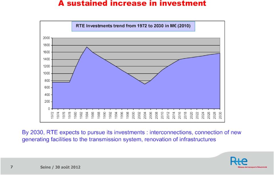
7 7

8 REVENUE SOURCES 2010 /


9 COST STRUCTURE 2010 /

10 A REGIONAL COMPANY 7 regional systems covering France Normandy-Paris, North-East, East, West, South-West, South-East, Rhône-Alpes Auvergne Power System units Regional network dispatching Regional network development Electricity Transmission units Network operation and maintenance Network development engineering /

11 1. Power supply of «Ile-de-France» and Paris 11


12 Part of the French 400 kv network 12

13 Ile-de-France power supply : a specific case in France A 400 kv loop diameter of 60 km A 225 kv loop diameter of 15 km 13

14 225 kv cable 225/20 kv substations A 225 kv radial cable feeds up to 3 substations 225/20 kv, forming 3 crowns 14

15 36 substations (225/20 kv) feed the 20 kv underground network 15

16 225 kv cables 100 MVA 20 kv 220/20 kv substation with 1x100 MVA transformer 16

17 225 kv cables 70 MVA 20 kv 70 MVA 220/20 kv substation with 2x70 MVA transformers partially guaranteed 17

18 Artère 1 Artère 2 Artère 3 Artère 4 Two 220/20 kv substations are connected by 4 MV arteries Each artery has 6 MV cables in // 18

19 220/20 kv substations 20 kv arteries Normal scheme of operation 19

20 Re feeding arteries after a loss of a 220/20 kv substation 20

21 Re feeding arteries after a loss of a 220/20 kv substation 21
22 On going evolutions to secure the 220/20 kv substations 22
23 kv Paris substations Civil Works characteristics 23
24 Example of three 225kV Substations 24
25 Gambetta 225kV Urban Substation 25
26 La Muette 225kV Urban Substation 26
27 Seine 225kV Building Substation 27
28 1. Fire protection: Urban substation: key concerns Objective: limit the effect of a fire in the substation building (explosion of power transformer) to protect the neighborhood Mitigation technique: use of very specific fire protection devices (on-site water tank, temperature/pressure sensors, fire-resistant walls ) 2. Noice cancellation: Objective: limit the sound emitted by the substation (cooling of power transformer) that troubles neighbours Mitigation technique: use of sound trap and antivibration plots 3. ElectroMagnetic Field: Objective: do not exceed the legal limit of 100 µt (High current circulating in the MV cables) outside the building Mitigation technique: move away those cables in the layout, use of reduced EMF laying 28
29 Usual urban substation layout longitudinal section Oil tank Oil Radiator Power transformer Ground level water water Fire protection 225kV metal-clad busbars (SF 6 insulated)
30 1. Detection loop Fire protection Pneumatic circuit (no electrical supply required due to reliability requirement) Quartz bulbs (burst when temperature increases) 225kV and 20kV breakers tripped off 2. First sprinkling circuit Water pushed by CO 2 tanks 3 spray rings Water tank of 12 m 3 Sprinkling for 2 min 3. Second sprinkling circuit Water pushed by CO 2 tanks 2 spray rings Water tank of 20 m 3 Sprinkling for 10 min
31 Transformer cooling and noise cancellation
32 Transformer cooling and noise cancellation
33 Seine 225kV transformer building 33
34 Seine 225kV transformer building Ground level 34
35 3. Seine substation: Gas Insulated Susbstation 35
36 SEINE substation : a key component of the Nord of Ile-de-France power supply An area of influence on the 225 kv loop surrounding Paris: inhabitants of Seine Saint Denis region and Paris (1st, 2nd, 9th et 18th arr.) Stade de France SNCF (TGV Nord, North suburbs ) Seine substation RATP (1/4 of subways and RER) Global cost of the projet : 75 M 36
37 The evolution of an area From an industrial past to an urban environment L Ile StSt-Denis Villeneuve-Villeneuve La--Garenne La Autoroute A86 Poste Seine Saint--Denis Saint To remove To buld 37 Saint--Ouen Saint Poste Ampère à 225 kv Project of ecological river quarter Project of Cité du Cinéma
38 Plan of Seine substation Transformers Towers GIS x Control Command Site actuel Projet Cité du Cinéma 38
39 Seine substation : Gas Insulated Substation The Gas Insulated Substation technology (GIS) RTE owns approx. 120 GIS (20 new S/S in the next 5 years). The first S/Ss built in 1969 are still in service The substation surface area is significantly reduced (1/10 of the equivalent AIS) SEINE was manufactured by SIEMENS Grenoble in 2009/2010 Equipped with digital SF6 monitoring 39
40 40
41 Radial cable : SEINE - CAULAINCOURT - PYRAMIDES SEINE Caulaincourt PYRAMIDES TR 611 TR 612
42 Caulincourt Plessis Gassot 2 Revest 1 Tr 631 Plessis Gassot 4 La courneuve Plessis Gassot 3 Tr 632 Couplage Ampère Tr 613 Revest 2 St Ouen 2 Plessis Gassot 1 Ampère Tr 612 St Ouen 1 42
43 Feeder bay Disconnector 1 Circuit breaker Current transformer Earthing switch Cable box 43
44 Other types of gas compartments Busbar earthing switch Maintenance disconnector Voltage transformer Line disconnector Voltage measurement on 1 phase Double cable box 44
45 Buffer compartments to increase availability during maintenance works and testing 45

46 Accessibility for the time-based maintenance Adding of a catwalk Mobile platform 46
47 Transformers The Power Transformers Installation 2 power transformers : Rated Power Sr : 100 MVA / 100 MVA / 65 MVA, Rated Voltage Ur : 225/64,5/21 kv - YNd11d11, cooling: ODAF. 2 shunt reactors connected to the LV winding (21 kv) of the power transformers: Réactive power: Q : 64 Mvar; cooling : ONAN, Rated Voltage Ur : 21 kv - Y. 2 neutral grounding transformers connected to the 63 kv network: Rated Power Sr : 500 kva; cooling : ONAN, Rated Voltage Ur : 68,5 / 11 kv - YNd11. 2 auxiliary transformers connected to the LV winding (11kV) of the grounding transformers: Rated Power Sr : 250 kva; cooling : ONAN The only one transformer of that kind in France Rated Voltage Ur : 10,5 kv / 400 V YNzn11. 47
48 Transformers and reactors The main alternatives 1. Two standard 100 MVA + 2 x 80 MVAr / 225 kv reactors (standard specification) 2. Two specific 100 MVA with a 65 MVA tertiary + 2 x 64 MVAr / 20 kv reactors The second solution was 25 % cheaper than the second one Main specifications Same Short circuit impedance and turn ratio as standard 100 MVA transformers Same overload capabilities as standard 100 MVA transformers Voltage dip < 3% on the 63 kv network when switching on the 64 MVAr reactor specific design 13,0 % MV HV - 1 % 15,1 % LV 64 MVAr LV HV MV 48
49 4. Introduction to underground lines design 49
50 Underground cable Outer semi-conductive layers (sheath test after laying) Outer and inner semiconductive layers (avoid point effect in the electric field) Outer sheath (PE) Metal screen (short-circuit current) Insulation (XLPE) Core conductor (current flow) 50

 Challenge: -Fault containment -Heat dissipation -Magnetic")
51 Cable laying Cables laid in plastic pipes to reduce disturbances from the civil works Cables laid: in PEHD pipes in the ground (on the left) or in PVC pipes embedded in concrete (on the right) Challenge: -Fault containment -Heat dissipation -Magnetic field 51
52 Cable design When current flows through the core conductor, losses lead to temperature rise in the cable. The limitation comes from the XLPE insulation which can withstand a maximum 60 C. Losses are due to: Joule losses in the core conductor (current flow) Dielectric losses in the insulation (not an ideal insulation) Joule losses in the metal screen (in case of induced current) The underground line rating comes from the capacity of the cable and its environment to dissipate heat. As a result it becomes paramount to take also into consideration the ground drying out, which affects the ground heat conductivity and can lead to cable fault. 52
53 Heat dissipation Joules losses in the metal screen Dielectric losses Joules losses in the core conductor Heat dissipation through the ground 53
54 Main factors for thermal design of the cable Core conductor size. Ground characteristics. Current circulation in the metal screen. Laying method (distance between cables, laying depth, ). Weather conditions. Heat sources in the ground. 54
55 Cable bonding When current flows through the core conductor, it induces voltage in the metal screen. This induced voltage must be controlled in order to protect people and equipments. First solution: direct grounding at both cable ends. Core Sheath Termination Direct grounding Problem: current circulation reduces the cable rating. This solution is adapted for low rating lines (under 600A). 55
56 Cable bonding Second solution: single point grounding (at one end or middle point). Result: no current in the screen but voltage build-up at one cable end. Surge arresters to protect the cable sheath Parafoudres de gaine Conducteur de terre isolé Insulated ground cable Problem: voltage limited to 400V in normal operation, thus limited to short lines (a few kilometres only). 56

57 Cable bonding Third solution: cross-bonding. Result: similar to direct grounding, but the screen cross-bonding erases the current circulation in the metal screen. Screeninterruption Sheath Core Surge arresters X-bonding pits Problem: more expensive (need for screen interruption joints protected by surge arresters). 57
58 Cable bonding Third solution: cross-bonding. Induced voltage in the metal screens. A B L U 0 L 2L 3L The maximum length L is defined according to the voltage withstand by the screen interruption joints. 58
59 GIS cable terminations 59
60 GIS cable terminations 60
61 Underground lines at Seine station Name Voltage (kv) Section (mm²) Core Screen Supplier Length (km) Grounding Ampère Seine Cu Al Silec 0.46 Single side in Seine Ampère Seine 1 (TR631) Cu Al Silec 0.78 Single side in Seine Ampère Seine Al Al Nexans 0.44 Single side in Seine Ampère Seine 2 (TR632) Cu Al Silec 0.63 Single side in Seine Plessis Gassot Seine Cu Al Prysmian 0.19 Single side in Seine Plessis Gassot Seine Cu Al Prysmian 0.14 Single side in Seine Plessis Gassot Seine 3 A&B 225 2x1600 Cu Al Prysmian 0.14 Single side in Seine Plessis Gassot Seine 4 A&B 225 2x1600 Cu Al Prysmian 0.12 Single side in Seine Revest-Seine 1 & / Prysmian 2.36 / 225 Al Al (SNCF 2 phases) 400 / Silec 2.33 Single side in Seine LS TR Al Al Prysmian 0.12 Single side in Seine LS TR Al Al Prysmian 0.05 Single side in Seine Caulaincourt - Seine / 1000 Cu Al Silec 4.55 Direct grounding Courneuve - Seine Cu Al Silec 7.67 Cross-bonding UG line between TR631 and its Neutral Point Al Al Nexans UG line between TR632 and its Neutral Point Al Al Nexans Seine St Ouen 1& Al Al Nexans 4.63 Middle point grounding 61
AMSC s Superconductor Cable Technologies for Electric Utilities
 International Workshop 2014 AMSC s Superconductor Cable Technologies for Electric Utilities Michael Ross, P.E. Managing Director of Superconductor Power Systems AMSC Corporate Facts Headquartered in MA,
Unified requirements for systems with voltages above 1 kv up to 15 kv
 (1991) (Rev.1 May 2001) (Rev.2 July 2003) (Rev.3 Feb 2015) Unified requirements for systems with voltages above 1 kv up to 15 kv 1. General 1.1 Field of application The following requirements apply to
Fault location on power cables. Fault location on power cables
 Fault location on power cables Fault location on power cables Contents: 1. Introduction 2. Construction of power cables 3. Cable faults 01. Introduction Fault location on communication and power cables
Respecting the environment
 MAIN FEATURE CHAPTER I RESEARCH WITH AN EYE ON THE FUTURE Respecting the environment Low power losses and a lesser visual impact on the landscape make Gas-Insulated Lines (GIL) a very environmentally friendly
SF 6 Gas Insulated Switchgear Type SDF for 170 kv
 Three Phase Encapsulated Type SF 6 Gas Insulated Switchgear Type SDF for 170 kv 06B1-E-0001 With Trustworthy Technology, Structure Fuji Electric as a manufacturer of comprehensive substation equipment
HV Submarine Cable Systems Design, Testing and Installation
 HV Submarine Cable Systems Design, Testing and Installation CIGRE Ireland Technical Seminar 6 th October 2010 Robert Donaghy Senior Consultant Engineer, ESB International Presentation Overview Applications
Modular Systems, PPMV, 2014 UniPack-G Glass Fiber Reinforced Polyester Compact Secondary Substation
 Modular Systems, PPMV, 2014 UniPack-G Glass Fiber Reinforced Polyester Compact Secondary Substation Index News Introduction Applications & Segments Main Components Applicable Standards Technical characteristics
SUPERCONDUCTING CABLE SYSTEMS
 SUPERCONDUCTING CABLE SYSTEMS INTRODUCTION An aging and inadequate power grid is widely seen as one of the greatest obstacles to the restructuring of power markets in the United States, Europe and elsewhere.
Undergrounding high voltage electricity transmission. The technical issues
 Undergrounding high voltage electricity transmission The technical issues This is an interactive PDF document with clickable links from the contents to all sections and back and also to URL and email links.
Electric Power Systems An Overview. Y. Baghzouz Professor of Electrical Engineering University of Nevada, Las Vegas
 Electric Power Systems An Overview Y. Baghzouz Professor of Electrical Engineering University of Nevada, Las Vegas Overview Power Generation Conventional power generation Power generation from renewables
How To Choose A Transformer
 Consider open loop MV network as an example source 1 source 2 NC NC NC or NO main MV switchboard A B Detail design of substation NC NC NC NO NC NC switchboard 1 switchboard 2 switchboard 3 MV MV MV LV
Max. Length of HTS Cables in the Future
 Max. Length of HTS Cables in the Future K. Schippl, Nexans Deutschland Industries, Hannover, Germany TOPICS: Limitation of the cable design: 1. Physical limitations 2. Shipping limitations 3. Maintenance
HIGH-CAPACITY HIGH TEMPERATURE SUPERCONDUCTING POWER CABLES
 HIGH-CAPACITY HIGH TEMPERATURE SUPERCONDUCTING POWER CABLES Jean-Maxime SAUGRAIN NEXANS Corporate VP Technical IASS Workshop Postdam May 13, 2011 Rationale High-capacity High Temperature Superconducting
Fundamentals of Modern Electrical Substations Part 1: Mission of Electrical Substations and their Main Components
 Fundamentals of Modern Electrical Substations Part 1: Mission of Electrical Substations and their Main Components Course No: E02-010 Credit: 2 PDH Boris Shvartsberg, Ph.D., P.E., P.M.P. Continuing Education
Comparison of GIS and AIS systems for urban supply networks
 Comparison of GIS and AIS systems for urban supply networks Studies carried out by ABB show that for urban supply networks the combination of HV gas-insulated switchgear (GIS) and HV cable has important
How To Monitor Water Penetration In A Cable Screen
 Detection and location of high voltage cable sheath damage with Water Penetration Monitoring*) Purpose of Monitoring System The expected lifetime of high voltage underground cables is more than 40 years,
www.siemens.com/energy High Voltage Circuit Breakers 3AP Type 72.5 kv to 800 kv Answers for energy.
 s www.siemens.com/energy High Voltage Circuit Breakers AP Type 7.5 kv to 800 kv Answers for energy. The AP High Voltage Circuit Breakers Available up to 800 kv Decades of our experience in high voltage
Hyperlinks are Inactive
 Prepared by: NIB/EOB PLANNING GUIDE FOR SINGLE CUSTOMER SUBSTATIONS SERVED FROM TRANSMISSION LINES 05503 Department: Electric T&D Section: T&D Engineering and Technical Support Approved by: G.O. Duru (GOD)
CAS 36 Ring Main Unit
 Power distribution networks Ring Main Unit Catalogue 2008 A new path for achieving your electrical installations A comprehensive offer The range is part of a comprehensive offer of products that are perfectly
Network Standard Advice No. 1420C 9/6/2011
 Network Standard Advice No. 1420C 9/6/2011 TO: Customers, Service Providers and Ausgrid Staff. Advisory Note on Changes to the Use of 11kV Cable Types. Introduction This Network Standard Advice (NSA) provides
Presentation of the France Transfo factories
 Presentation of the France Transfo factories France Transfo's internationally recognised and highly esteemed expertise is today exported to more than 80 countries throughout the world. Over the past 15
AORC Technical meeting 2014
 http : //www.cigre.org B1-1055 AORC Technical meeting 2014 220 kv Long Distance Underground HVAC Cable Circuit NAVEED RAHMAN Nexans Olex Melbourne, Australia SUMMARY In 2009, the Victorian state government
The Intelligent AX1 Switchgear for Medium Voltage
 The Intelligent AX1 Switchgear for Medium Voltage Leif Lundin, Manager of Research and Development, Division Medium Voltage and Compact Substations, ABB Distribution, Sweden Abstract The newly launched
ES281 COMPANY-SPECIFIC APPENDICES TO ENA ENGINEERING RECOMMENDATION G81 PART 1
 ES281 COMPANY-SPECIFIC APPENDICES TO ENA ENGINEERING RECOMMENDATION G81 PART 1 Design and Planning Specification for New Low Voltage Installations for Housing Developments 1. SCOPE This appendix to ENA
Transformer Design & Design Parameters
 Transformer Design & Design Parameters - Ronnie Minhaz, P.Eng. Power Transmission + Distribution GENERATION TRANSMISSION SUB-TRANSMISSION DISTRIBUTION DISTRIBUTED POWER 115/10 or 20 kv 500/230 230/13.8
BL20A0501 Electricity distribution technology. Introduction Jarmo Partanen
 BL20A0501 Electricity distribution technology Introduction Jarmo Partanen Introduction to ED Prof. Jarmo Partanen, D.Sc Jukka Lassila Topics of lectures Introduction to Electricity Distribution, 27.10
6 ELECTRICAL PARAMETERS
 6 ELECTRICAL PARAMETERS For power, low voltage and medium voltage cables, cross section nominal areas are calculated in taking into account several parameters as: permissible current carrying capacities
Chapter 1. Network Structures
 Chapter 1 Network Structures Definition Standard IEC 60038 defines voltage ratings as follows: Low voltage (): for a phase-to-phase voltage of between 100 V and 1,000 V, the standard ratings are: 400 V
environment briefing02
 PRODUCED BY THE SAFETY, HEALTH & ENVIRONMENT GROUP OF THE ENERGY NETWORKS ASSOCIATION - JULY 2006 environment briefing02 transporting electricity Overhead Lines or Underground Cables? Introduction The
DESCRIPTION DWG DESCRIPTION DWG
 DESCRIPTION DWG DESCRIPTION DWG Ferroresonance 3451/1 3451/2 3451/3 Electro-magnetic Fields (EMF) 3462/1 HV & LV Insulators (Links) 3463/1 A ORIGINAL ISSUE B 14.07.09 APPROVED DATE J. Brooks 25.02.03 INDEX
State, trends and evolutions of HV/EHV power cables systems and contributions of SC B1 to their ongoing progress
 0611-048-Mep229 12/12/06 6:44 Page 22 State, trends and evolutions of HV/EHV power cables systems and contributions of SC B1 to their ongoing progress Reinhard SCHROTH, Chairman of SC B1 2002-2006 High
Primary and Secondary Electrical Distribution Systems
 Primary and Secondary Electrical Distribution Systems Critical Facilities Round Table 12th Quarterly Membership Meeting June 2, 2006 David D. Roybal. P.E. Eaton Electrical Cutler-Hammer Products Utility
Stephen G. Whitley, Senior Vice President & Chief Operating Officer
 Peter T. Brandien Vice President, System Operations To: Stephen G. Whitley, Senior Vice President & Chief Operating Officer From: Peter T. Brandien Re: Discussion of Cable Technologies Under Evaluation
CHAPTER VIII LINE PLANT SYSTEM COMMUNICATION THROUGH RE CABLE
 CHAPTER VIII LINE PLANT SYSTEM COMMUNICATION THROUGH RE CABLE 8.1 SYSTEM 8.1.1 Armoured, screened underground cables are used for control communication in electrified areas to limit induction effect. 8.2
Analytical Report RF high voltage cable accessories market
 Analytical Report RF high voltage cable accessories market High voltage cable accessory market of Russia, development trends Cable accessories are special devices aimed to connect cables mechanically and
Interfacing electrification and system reliability. Earthing of AC and DC railways 4,10,13
 Interfacing electrification and system reliability Roger White Professional Head of Electrification and Plant Rail Abstract Integration is the term given to ensuring that the different elements of an electrified
HIGH- AND EXTRA-HIGH-VOLTAGE GLOBAL CABLE SYSTEM SOLUTIONS Rely On Our Experience... Experience Our Capabilities
 HIGH- AND EXTRA-HIGH-VOLTAGE GLOBAL CABLE SYSTEM SOLUTIONS Rely On Our Experience... Experience Our Capabilities RELY ON OUR EXPERIENCE... EXPERIENCE OUR CAPABILITIES For close to half a century, Silec
EMTP STUDIES PERFORMED TO INSERT LONG AC CABLES IN THE FRENCH GRID
 Tension (kv) Impedance (Ohms) EMTP STUDIES PERFORMED TO INSERT LONG AC CABLES IN THE FRENCH GRID frequency (Hz) Simon DESCHANVRES Yannick VERNAY RTE, CNER, Substations Department t (ms) EMTP-RV Users Group
For a phase-to-phase voltage between 100 V and 1000 V. The standard ratings are: 400 V - 690 V - 1000 V (at 50 Hz)
") 24 1. NETWORK CONFIGURATIONS definition Standard IEC 38 defines voltage ratings as follows: - Low voltage () For a phase-to-phase voltage between 100 V and 1000 V. The standard ratings are: 400 V - 690
24 1. NETWORK CONFIGURATIONS definition Standard IEC 38 defines voltage ratings as follows: - Low voltage () For a phase-to-phase voltage between 100 V and 1000 V. The standard ratings are: 400 V - 690
Comparative study for cables and busbars
 Comparative study for cables and busbars Preliminary considerations To compare the prices of two categories of product as different as traditional cables and busbars, it is necessary to make some preliminary
E-Highway2050 WP3 workshop April 15 th, 2014 Brussels
 E-Highway2050 WP3 workshop April 15 th, 2014 Brussels High voltage underground and subsea cable technology options for future transmission in Europe Ernesto Zaccone, Chairman Europacable High Voltage Systems
4 IX D N E P P A Installation methods Current-carrying capacity and voltage drop for cables Reference method IET Wiring Matters
 8 Appendix 4 of BS 7671 by Mark Coles Appendix 4, Current-carrying capacity and voltage drop for cables and flexible cords, has seen significant changes with the publishing of BS 7671:2008. This article
ScottishPower Distribution Cables & Equipment. Metal Theft
 ScottishPower Distribution Cables & Equipment Metal Theft April 2012 As an aid to deterring to metal theft this booklet has been put together to help identify the types of utility power cables and associated
The electrical energy produced at the gen
 300 300 Principles of Power System CHAPTER CHAPTER 12 Distribution Systems General 12.1 Distribution System 12.2 Classification of Distribution Systems 12.3 A.C. Distribution 12.4 D.C. Distribution 12.5
On-line monitoring of substation condition a Romanian experience. V. ZAHARESCU, Vl. ROSCA Nova Industrial SA. CN Transelectrica SA Romania
 21, rue d Artois, F-75008 PARIS http : //www.cigre.org B3_201 CIGRE 2012 On-line monitoring of substation condition a Romanian experience C. MOLDOVEANU*, V. BREZOIANU, S. GAL, V. METIU, A. VASILE, V. URSIANU,
ELECTRICAL ENGINEERING DESIGN CRITERIA APPENDIX F
 ELECTRICAL ENGINEERING DESIGN CRITERIA APPENDIX F TABLE OF CONTENTS Appendix F - Electrical Engineering Design Criteria F.1 Introduction...F-1 F.2 Codes and Standards...F-1 F.3 Switchyard and Transformers...F-1
Power Transmission and Distribution. Shunt reactors for medium and highvoltage. From development to use
 Power Transmission and Distribution Shunt reactors for medium and highvoltage networks: From development to use From the beginning up to today more quality and reliability for your network A safe power
Discussion on Class I & II Terminology. IEEE PES Transformers Committee Fall Meeting 2011 Boston, MA
 Discussion on Class I & II Terminology IEEE PES Transformers Committee Fall Meeting 2011 Boston, MA What is Class I & II? C57.12.00 2010 is the only document we have that defined these terms. 5.10 Insulation
ESB Networks Response. ERGEG Consultation. Voltage Quality Regulation in Europe
 NETWORKS ESB Networks Response to ERGEG Consultation on Voltage Quality Regulation in Europe Date: 22 February 2007 Distribution System Operator ESB Networks Page 1 of 12 Contents 1.0 INTRODUCTION...3
Emirates Aluminium starts up World s first fully integrated power distribution system from ABB
 Reprint from Aluminium World 2009, Volume 2 Emirates Aluminium starts up World s first fully integrated power distribution system from ABB Emirates Aluminium (EMAL), a joint venture between Abu Dhabi s
Permissible ambient temperature Operation Storage, transport
 The Sitras PRO combined DC protective unit and controller is used in the power supply for DC railways in mass transit and main-line systems up 3,000 V DC. It protects DC switch gear and contact line systems
Product brochure Multi Functional Switchgear PASS M00 72.5 kv Flexible and compact switchgear solutions for windfarms
 Product brochure Multi Functional Switchgear PASS M00 72.5 kv Flexible and compact switchgear solutions for windfarms The future of Wind Farms As offshore wind farms move towards deploying higher capacity
MV, HV AND EHV SWITCHGEAR TESTING & COMMISSIONING
 Training Title MV, HV AND EHV SWITCHGEAR TESTING & COMMISSIONING Training Duration 5 days Training Date MV, HV and EHV Switchgear Testing & Commissioning 5 20 24 Apr $3,750 Dubai, UAE In any of the 5 star
Grounding of Electrical Systems NEW CODE: Grounding and Bonding
 Grounding of Electrical Systems NEW CODE: Grounding and Bonding Presented By Scott Peele PE Grounding of Electrical Systems Outline Defining the Terms Why should I Ground? Types of Grounding Systems Separately
ABB Power Systems. Substations References
 ABB Power Systems Substations References Jingzhou, China BA PTPS - 2 - Connection of power from the 3-Gorges-Project to Guandong province (940km away) HVDC Transmission station, Filter banks and GIS Extremely
Transformers. Special transformers Reactors products
 Transformers Special transformers Reactors products Reactors Custom designed, custom built ABB Oy Transformers has extensive experience and numerous references from different reactor applications, having
HVDC Light, a tool for electric power transmission to distant loads
 Presented at VI Sepope Conference, Salvador, Brazil, May 1998 HVDC Light, a tool for electric power transmission to distant loads by Gunnar Asplund Kjell Eriksson* Ove Tollerz ABB Power Systems AB ABB
ANCILLARY EQUIPMENT AND ELECTRICAL EQUIPMENT Power Supply Systems and Electrical Equipment for Desalination Plants - Y.M. Hamud and A.H.
 POWER SUPPLY SYSTEMS AND ELECTRICAL EQUIPMENT FOR DESALINATION PLANTS Y.M. Hamud and A.H. Anwar Abu Dhabi Water and Electricity Authority, Abu Dhabi, UAE Keywords : Electrical System, Network for Desalination,
Cables, Cable Laying & Accessories Manual
 Distribution Business Cables, Cable Laying & Accessories Manual Database ref: File Ref: Title Page & Revision Log For Cables & Access v4 - Nov 2003.doc Manual Name: Cables & Accessories Manual Version
THE PATHWAY TO POWER HIGH-VOLTAGE CABLES
 THE PATHWAY TO POWER HIGH-VOLTAGE CABLES TABLE OF CONTENTS HIGH-VOLTAGE CABLES 3 Advantages of XLPE-insulated cable systems 3 PROPOSAL 4 Cable systems 4 Providing System Solutions 4 Continuous temperature
Choosing for tranquility
 Medium voltage switchgear with withdrawable circuit breakers MCset Choosing for tranquility Web enabled Power & Control Building a New Electric World Innovation at every level Busbar compartment This section
High Voltage Electrical Equipment Failure Diagnosis. Presented by: Spencer Tang & Terence Ng T&T Inspection & Engineering Sdn Bhd
 High Voltage Electrical Equipment Failure Diagnosis Presented by: Spencer Tang & Terence Ng T&T Inspection & Engineering Sdn Bhd High Voltage Electrical Equipment Failure Diagnosis Definition of High Voltage
HIGH VOLTAGE XLPE CABLE SYSTEMS. Technical User Guide
 HIGH VOLTAGE XLPE CABLE SYSTEMS Technical User Guide Content 1. General information on High Voltage XLPE Cable Systems 1.1. Introduction 1.2. Cable selection process 1.3. Service life 3 3 3 4 2. Cable
How To Understand The Electrical Power Supply Of A Power Supply System
 17 Circuit diagram symbols E 18 CIRCUIT DIAGRAM SYMBOLS electrical network elements three-phase line or cable single-phase line or cable short circuit earth electrode outgoing feeder supply incoming feeder
Development of a 500-kV DC XLPE Cable System
 by Satoru Maruyama *, Noboru Ishii *, Michihiro Shimada *, Shinji Kojima * 2, Hideo Tanaka * 3, Mitsumasa Asano * 4, Tetsuya Yamanaka * 4, and Shin ichi Kawakami * 4 This paper describes development work
High Voltage Systems. Today. The history of cables
 High Voltage Cables High Voltage Systems Today Prysmian Cables and Systems B.V. is part of the Prysmian Group, a leading player in the industry of high-technology cables and systems for energy and telecommunications,
Secondary Unit Substations
 14 SWITCHGEAR Secondary Unit Substations Overview Siemens offers a wide variety of unit substation designs to meet customer requirements. A unit substation consists of one or more transformers mechanically
METAL-CLAD AND METAL-ENCLOSED SWITCHGEAR 3.6KV~40.5KV. tgood.com. Energy. Fast.
 METAL-CLAD AND METAL-ENCLOSED SWITCHGEAR 3.6KV~40.5KV tgood.com Energy. Fast. TGOOD produces over 5000 switchgear units annually for projects around the globe PRODUCT OVERVIEW Integral substation component
APPLICATION ORIENTED DESIGN OF CABLES
 APPLICATION ORIENTED DESIGN OF CABLES Mrs. Rohini Bhattacharyya, Dubai cables Ltd.P. O. Box 11529,Dubai. [email protected] Mr. Nawaf Ahmad Al Mohaideb Dubai Cables Ltd. P. O. Box 11529, Dubai. [email protected]
Together we create reliable products, thus ensuring development of power industry of continents.
 PRODUCT CATALOGUE Together we create reliable products, thus ensuring development of power industry of continents. By continuous improvement we transform our knowledge, energy and experience of the generations
Medium voltage products UniSec for Smart Grid Air-insulated medium-voltage secondary distribution switchgear
 Medium voltage products UniSec for Smart Grid Air-insulated medium-voltage secondary distribution switchgear Index 3 Overview 4 Standard Levels 6 Monitoring & Control 7 Measurements 8 Protection & Logic
Electrical for Detached Garages: Updated Feb 19, 2016 for 2015 CE Code in force Jan. 1, 2016. Underground branch circuit feeding a detached garage:
 Electrical for Detached Garages: Updated Feb 19, 2016 for 2015 CE Code in force Jan. 1, 2016 * Garage construction requires permits (electrical, building) * Permits must be applied for at the time. * Dial
Cable Consulting International
 Cable Consulting International Brian Gregory BSc, CEng, MIEEE, FIEE Technical Director www.cableconsulting.net Alan Williams BSc, CEng, MIEE Senior Consultant 1 FEASIBILITY STUDY for 500 kv AC UNDERGROUND
ELECTRICAL INSULATION TESTING OF HV EQUIPMENT UP TO 33kV
 1. SCOPE This document details PowerSystems requirements for electrical testing of HV Equipment up to and including 33kV. 2. ISSUE RECORD This is a Reference document. The current version of Controlled
F.C. Chan General Manager, CLP Engineering Ltd., Hong Kong SAR, China
 ELECTRIC POWER DISTRIBUTION SYSTEMS F.C. Chan General Manager, CLP Engineering Ltd., Hong Kong SAR, China Keywords: Distribution system planning, Load characteristics, Subtransmission Lines, Distribution
IEC and IEEE Standards for High-Voltage Switchgear and Controlgear Present Situation and Future Evolution
 IEC and IEEE Standards for High-Voltage Switchgear and Controlgear Present Situation and Future Evolution Denis Dufournet Chairman IEC TC 17 & SC17A Fellow IEEE Senior Expert Areva T&D Mumbai, January,
261000 Medium Voltage Electrical Distribution
 Sections Included In This Standard: 1.1 General 1.2 Underground Cable 1.3 Medium Voltage Switches 1.4 Transformers 1.5 Electrical Manholes 1.6 Switch Vaults 1.7 Distribution Switchgear/Switchboards This
Earthing Guidance Notes
 Central Networks Earthing Manual Section E2 Earthing Guidance Notes Version: 2 Date of Issue: September 2007 Author: Nigel Johnson Job Title: Earthing Specialist Approver: John Simpson Job Title: Head
EDS 02-0027 11KV TRIPLEX CABLE
 THIS IS AN UNCONTROLLED DOCUMENT, THE READER MUST CONFIRM ITS VALIDITY BEFORE USE Document Number: EDS 02-0027 ENGINEERING DESIGN STANDARD EDS 02-0027 11KV TRIPLEX CABLE Network(s): EPN, LPN, SPN Summary:
MINISTERIE VAN ECONOMISCHE ZAKEN GENERAL COST COMPARISON BETWEEN UNDERGROUND CABLES AND O.H. LINE SYSTEMS FOR H.V. TRANSMISSION
 MINISTERIE VAN ECONOMISCHE ZAKEN GENERAL COST COMPARISON BETWEEN UNDERGROUND CABLES AND O.H. LINE SYSTEMS FOR H.V. TRANSMISSION REPORT ON NETWORK RELIABILITY ASPECTS OF THE CHOICE LINE VERSUS CABLE FOR
Power transformers. Special transformers Railway
 Power transformers Special transformers Railway A leader in railway systems Our compact and low-weight transformers fully comply with the customer s specifications. The products are developed together
Assessment of the Technical Issues relating to Significant Amounts of EHV Underground Cable in the All-island Electricity Transmission System
 Assessment of the Technical Issues relating to Significant Amounts of EHV Underground Cable in the All-island Electricity Transmission System Summary Report November 2009 Technical Report on using EHV
Lightning Arresters P30027 18 KVA P30038 10 KVA. Description & Installation
 Lightning Arresters P30027 18 KVA P30038 10 KVA Description & Installation Printed in USA 09/11 TO330 Rev. B Table of Contents Page 1.0 SCOPE 2 2.0 PRODUCT OVERVIEW 2 2.1 Intended Uses 2 2.2 Lightning
CONNECTING YOU TO SPECIALIST ELECTRICAL SUPPORT services
 CONNECTING YOU TO SPECIALIST ELECTRICAL SUPPORT services SpecialistS IN ELECTRICAL SUPPORT SERVICES TO MINING, UTILITIES & industry Ampcontrol is committed to supporting our customers to maintain efficient
INTERNATIONAL POWER DISTRIBUTION CONGRESS CIDEL ARGENTINA 2002
 INTERNATIONAL POWER DISTRIBUTION CONGRESS CIDEL ARGENTINA 2002 NEW GAS INSULATED SWITCHGEAR (GIS) FOR ALL MEDIUM VOLTAGE APPLICATIONS H. Fink, ABB Calor Emag Mittelspannungs GmbH; M. Hyrenbach, ABB Calor
Power products and systems. Intelligent solutions for power distribution Zone concept
 Power products and systems Intelligent solutions for power distribution Zone concept Securing continuous power supply ABB is one of the world's leading power and automation technology companies whose products,
Undergrounding high voltage electricity transmission lines. The technical issues
 Undergrounding high voltage electricity transmission lines The technical issues Contents Introduction 03 National Grid electricity transmission 03 an overview Section 1 Insulating underground cables 04
How the National Grid System Operates. Chris Gorman Lead Account Executive Syracuse
 How the National Grid System Operates Chris Gorman Lead Account Executive Syracuse 2 Parts of the Electric System Parts of the Electric System 1. Generating Station: Produces Electricity. 2. Transmission
CyberFortress Data Center at Innovation Park Infrastructure and Topology Guide. Innovation Park Charlotte. NC 28262. DRAFT V0.
 Innovation Park Charlotte. NC 28262 DRAFT V0.1 Page 2 CyberFortress Data Center at Innovation Park BECO South purchased Innovation Park in March 2010 and immediately launched a dramatic top-to-bottom $30M
Integrated Development and Assessment of New Thermoplastic High Voltage Power Cable Systems
 21, rue d Artois, F-75008 PARIS B1-215 CIGRE 2012 http : //www.cigre.org Integrated Development and Assessment of New Thermoplastic High Voltage Power Cable Systems Mike FAIRHURST (1), Ankit GOWADIA (1),
HIGH VOLTAGE SHORE CONNECTION
 Guide for High Voltage Shore Connection GUIDE FOR HIGH VOLTAGE SHORE CONNECTION NOVEMBER 2011 American Bureau of Shipping Incorporated by Act of Legislature of the State of New York 1862 Copyright 2011
4160: THE GREEN 480 MEDIUM VOLTAGE ELECTRICAL SYSTEMS
 4160: THE GREEN 480 MEDIUM VOLTAGE ELECTRICAL SYSTEMS for DATA CENTERS Michael Mosman, PE Chief Technical Officer CCG Facilities Integration Incorporated FACILITIES INTEGRATION INCORPORATED MEDIUM VOLTAGE
Generator Stator Protection, under/over voltage, under /over frequency and unbalanced loading. Ramandeep Kaur Aujla S.NO 250447392
 1 Generator Stator Protection, under/over voltage, under /over frequency and unbalanced loading By Ramandeep Kaur Aujla S.NO 250447392 ES 586b: Theory and applications of protective relays Department of
Practical Transformers: Operation, Maintenance and Testing
 Practical Transformers: Operation, Maintenance and Testing YOU WILL GAIN: 4 hour live, practical online course Saturday, 2 nd May, 2015 8.00AM WST; 10.00AM AEST An understanding of the fundamental theory
DELHI METRO RAIL CORPORATION LIMITED. (A Joint Venture of Govt. of India & GNCTD) MASS RAPID TRANSPORT SYSTEM PHASE III. Contract: - CE -16 VOLUME-6
 MASS RAPID TRANSPORT SYSTEM PHASE III. Contract: - CE -16 VOLUME-6") DELHI METRO RAIL CORPORATION LIMITED (A Joint Venture of Govt. of India & GNCTD) MASS RAPID TRANSPORT SYSTEM PHASE III TURNKEY PROJECT OF DESIGN, SUPPLY, LAYING, JOINTING, TESTING AND COMMISSIONING OF
DELHI METRO RAIL CORPORATION LIMITED (A Joint Venture of Govt. of India & GNCTD) MASS RAPID TRANSPORT SYSTEM PHASE III TURNKEY PROJECT OF DESIGN, SUPPLY, LAYING, JOINTING, TESTING AND COMMISSIONING OF
M. GELDON Brugg Kabel CZ. Ing. D. RÚŽEK PREdistribuce. Switzerland Czech Rep. Czech Rep. Czech Rep., Switzerland Germany
 21, rue d Artois, F-75008 PARIS Paper number CIGRE 2012 http : //www.cigre.org 6 characters (to be provided later) Correlation between calculated transmission capacity and actual one D. WALD* Eifelkabel
High-Voltage GIS yesterday - today - tomorrow
 High-Voltage GIS yesterday - today - tomorrow Peter Glaubitz, Siemens AG, Principal Expert GIS-Technology siemens.at/future-of-energy Table of content GIS yesterday beginning and establishment of Gas-
Estimation of electrical losses in Network Rail Electrification Systems
 Estimation of electrical losses in Network Rail Electrification Systems Page 1 of 16 Contents 1. BACKGROUND...3 2. PURPOSE...3 3. SCOPE...3 4. DEFINITIONS & ABBREVIATIONS...4 5. NETWORK RAIL INFRASTRUCTURE
EFFICIENT ELECTRICAL ENERGY TRANSMISSION AND DISTRIBUTION INTERNATIONAL ELECTROTECHNICAL COMMISSION
 EFFICIENT ELECTRICAL ENERGY TRANSMISSION AND DISTRIBUTION INTERNATIONAL ELECTROTECHNICAL COMMISSION EFFICIENT ELECTRICAL ENERGY TRANSMISSION AND DISTRIBUTION 1 EFFICIENT ELECTRICAL ENERGY TRANSMISSION