Together we create reliable products, thus ensuring development of power industry of continents.
|
|
|
- Leslie Robinson
- 10 years ago
- Views:
Transcription
1 PRODUCT CATALOGUE
2

3 Together we create reliable products, thus ensuring development of power industry of continents. By continuous improvement we transform our knowledge, energy and experience of the generations into common success. We enjoy what we do and are proud of it. PRODUCT CATALOGUE A

4 I. POWER TRANSFORMERS Generator transformers Autotransformers Transformers for substations of transmission electric networks Auxiliary and standby transformers Transformers for DC transmission lines and high-capacity converter substations of tie-lines Special transformers 6.1. Transformers for metallurgical enterprises Transformers for railway substations Regulating transformers Furnace transformers Mine transformer...24 II. ELECTRICAL REACTORS 1. Shunt reactors Neutral reactors...28 III. CONTROLLABLE SHUNT REACTORS...30

5 The present catalogue introduces the major types of oil immersed power transformers and electrical reactors produced by ZTR. The catalogue gives an opportunity to evaluate the wide range of transformer and reactor equipment designed and manufactured by ZTR during more than 60 years. It includes standard types of equipment as well as non-standard ones manufactured under individual specific requirements of customers from 84 countries worldwide. 3 ZTR product range covers oil immersed power transformers, electrical reactors and controllable shunt reactors with power range from 1 MVA to 1250 MVA and voltage classes from 10 kv to 1150 kv inclusive, of different purposes, climatic and seismic conditions. Individual non-standard customers requirements for power equipment are successfully met due to the ZTR broad experience in design and manufacturing of unique types of transformers and electrical reactors. Up-to-date technology and high-skilled experienced personnel guaranty manufacturing of high quality and reliable equipment.

6 4 QUALITY MANAGEMENT SYSTEM: Quality management system of ZTR complies with international ISO 9001:2008 standard. Equipment is designed in accordance with the GOST, DSTU, IEC, ANSI, BS, IRAM and other national standards as well as with technical conditions and requirements of customer. Due to its high scientific and technical potential, long experience in design and manufacturing of advancedtechnology equipment, ZTR is able to fulfil any non-standard requirements of Customers and take orders for transformers and reactors not presented in this catalogue.

7 Type of Cooling: ONAN natural circulation of air and oil; ONAF forced circulation of air and natural circulation of oil; 5 OFAF - forced circulation of air and oil with nondirectional oil flow; OFWF - forced circulation of air and oil with directional oil flow; OFWF - forced circulation of water and oil with nondirectional oil flow; Tap changer type: OLTC On-Load tap changer; OCTC Off-circuit tap changer; LV split winding LV split

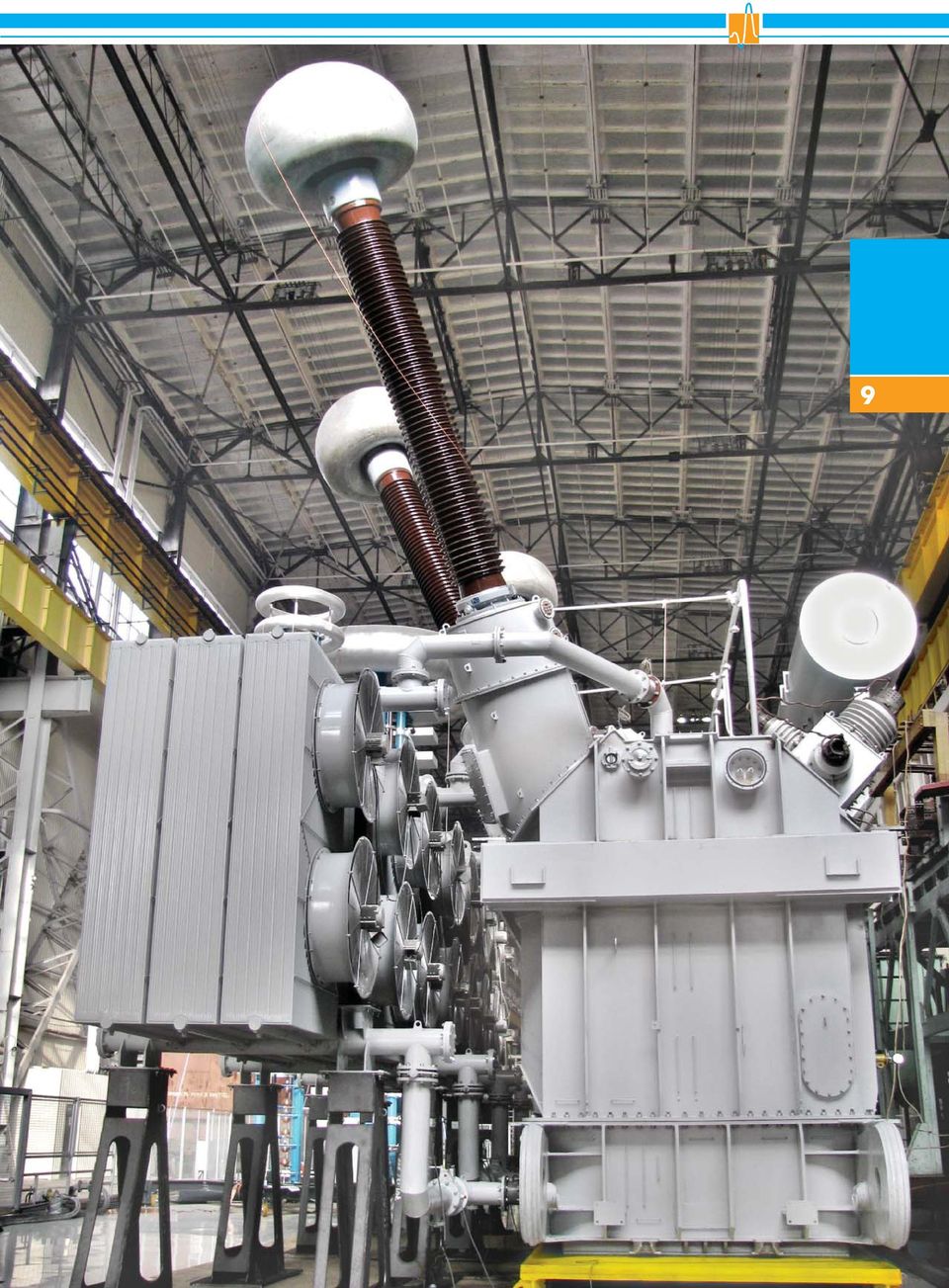
8 I. POWER TRANSFORMERS: 6 1. Generator transformers Generator transformers manufactured by ZTR are intended for transmission of the power generated by electric power plant to high voltage bus network. ZTR manufactures one-phase and three-phase generator transformers rated for capacity up to 1250 MVA and voltage up to 750 kv. Transformers can be produced with split generator windings for simultaneous connection to two and more generators. Transformers can be equipped with in-built on-load or offcircuit tap changers.

9 Òàbl. 1. Generator transformers Description Voltage, kv Rated capacity, MVA HV Rated voltage, kv LV Vector group Cooling Tap Changer Single phase two-winding transformers 417 MVA, 750 kv, LV split / 3 20,0; 24,0 YNd11d11 (in 3-phase group) OFWF MVA, 750 kv / 3 24,0 YNd11 (in 3-phase group) OFAF MVA, 500 kv, LV split / 3 15,75 YNd11d11 (in 3-phase group) OFWF MVA, 420 kv / 3 24,0 YNd11 (in 3-phase group) OFAF - 63,3 MVA, 220 kv, LV split / 3 10,5 YNd11d11 (in 3-phase group) OFAF - 66,667 MVA, 220 kv, LV split / 3 11,0 YNd11d11 (in 3-phase group) ONAF - 7 Three phase two-winding transformers 1000 MVA, 500 kv YNd11 ODWF MVA, 500 kv ,75 YNd11 OFWF MVA, 500 kv ,75; 20,0; 24,0 YNd11 OFAF MVA, 500 kv ,75; 20,0; 24,0 YNd11 OFWF MVA, 500 kv ,75; 20,0 YNd11 OFAF MVA, 500 kv ,75; 20,0 YNd11 OFWF MVA, 500 kv ,75 YNd11 OFAF MVA, 500 kv ,8; 15,75; 20,0 YNd11 OFAF MVA, 500 kv ,8; 15,75 YNd11 OFWF MVA, 400 kv YNd5 OFWF OLTC 630 MVA, 400 kv ,75; 20,0; 24,0 YNd11 OFWF MVA, 347 kv ,0 YNd11 ONAF OCTC 1250 MVA, 330 kv YNd11 ODWF MVA, 330 kv YNd11 ODWF MVA, 330 kv ,75; 20,0; 24,0 YNd11 OFWF MVA, 330 kv ,75 YNd11 OFAF OCTC 250 MVA, 330 kv ,8; 15,75 YNd11 OFAF MVA, 245 kv YNd11 OFAF OLTC 1000 MVA, 220 kv YNd11 ODWF MVA, 220 kv ,75; 20,0; 24,0 YNd11 OFWF MVA, 220 kv ,75; 20,0 YNd11 OFAF MVA, 220 kv ,8; 15,75 YNd11 OFAF MVA, 220 kv ,5 YNd11 OFAF OCTC 200 MVA, 220 kv ,8; 15,75 YNd11 OFAF OCTC 160 MVA, 220 kv ,5 YNd11 OFAF OCTC 125 MVA, 220 kv ,5; 13,8 YNd11 OFAF OCTC
 OFWF - 417 MVA, 420 kv 420 417000 420/ 3 24,0 YNd11 (in 3-phase group) OFAF - 63,3 MVA, 220 kv, LV split 220 63300 242/ 3 10,5 YNd11d11 (in 3-phase group) OFAF - 66,667 MVA, 220 kv, LV split")
10 I. POWER TRANSFORMERS Description Voltage, kv Rated capacity, MVA HV Rated voltage, kv LV Continue Òàbl. 1. Generator transformers Vector group Cooling OLTC 100 MVA, 220 kv ,0 YNyn0+d OFAF OLTC 80 MVA, 220 kv ,3-13,8 YNd11 ONAF OCTC 61 MVA, 154 kv ,8 YNd11 ONAF OCTC MVA, 150 kv ,8 YNd11 OFWF MVA, 150 kv ,5 YNd11 OFAF MVA, 150 kv ,5; 13,8 YNd11 OFWF - 95 MVA, 150 kv ,8 YNd11 OFAF - 55,5 MVA, 132 kv ,5 11 YNd1 OFWF OCTC 27,8 MVA, 132 kv ,5 11 YNd1 OFWF OCTC 180 MVA, 121 kv ,75 YNd11 ONAF OCTC 400 MVA, 110 kv YNd11 OFAF MVA, 110 kv ,75 YNd11 OFAF MVA, 110 kv ,5 YNd11 OFAF OCTC 200 MVA, 110 kv ,8; 15,75 YNd11 OFAF OCTC 180 MVA, 110 kv ,8; 15,0 YNd11 OFAF OCTC 160 MVA, 110 kv ,5 YNd11 OFAF OCTC 125 MVA, 110 kv ,5; 13,8 YNd11 OFAF OCTC 90 MVA, 110 kv, LV split ,3 YNd11d11 ONAF - 80 MVA, 110 kv ,5 YNd11 OFAF OLTC 80 MVA, 110 kv ,5 YNd11 ONAF OCTC 40 MVA, 110 kv ,5 YNd11 ONAF OCTC 25 MVA, 110 kv ,5 YNd11 ONAF OCTC

11 9
12 I. POWER TRANSFORMERS Autotransformers Autotransformers are intended for interconnection of two high-voltage networks of different voltages, as well as for regulation of power flows in networks and maintenance of required voltage levels in on-load conditions by means of in-built on-load tap changers. ZTR manufactures autotransformers with capacity up to 800 MVA and voltage up to 1150 kv. Normally transformers manufactured by Zaporozh transformator JSC are equipped with delta-connected stabilizing tertiary winding which can be used for power supply to local consumers.

13 Òàbl. 2. Autotransformers Description Voltage, kv Rated capacity, MVA Rated voltage, kv HV MV LV Vector group Cooling Tap Changer Single phase three-winding autotransformers 667 MVA, 1150/500 kv / 3 500/ 3 20,0 417 MVA, 750/500 kv / 3 500/ 3 10,5 417 MVA, 750/500 kv / 3 500/ 3 10,5; 15, MVA, 750/330 kv / 3 330/ 3 15, MVA, 750/330 kv / 3 330/ 3 15, MVA, 750/330 kv / 3 330/ 3 15, MVA, 500/220 kv / 3 230/ 3 6,3-38,5 167 MVA, 500/220 kv / 3 230/ 3 10,5-38,5 167 MVA, 500/220 kv / 3 230/ 3 10,5-38,5 167 MVA, 500/330 kv / 3 330/ 3 10,5 150 MVA, 500/220 kv / 3 225/ 3 35,0 135 MVA, 500/110 kv / 3 121/ 3 10,5 267 MVA, 400/231 kv / 3 231/ 3 31,5 120 MVA, 220/110 kv / 3 121/ 3 13,8 Three phase three-winding autotransformers YNauto0d11 (in 3-phase group) OFAF - YNauto0d11 (in 3-phase group) OFAF OCTC YNauto0d11 (in 3-phase group) OFAF OLTC YNauto0d11 (in 3-phase group) ONAF OLTC YNauto0d11 (in 3-phase group) OFAF OLTC YNauto0d11 (in 3-phase group) OFAF OLTC YNauto0d11 (in 3-phase group) OFAF OLTC YNauto0d11 (in 3-phase group) ONAF OLTC YNauto0d11 (in 3-phase group) OFAF OLTC YNauto0d11 (in 3-phase group) OFAF OLTC YNauto0d11 (in 3-phase group) OFAF OLTC YNauto0d11 (in 3-phase group) OFAF OLTC YNauto0d11 (in 3-phase group) OFAF OLTC YNauto0d11d11 (in 3-phase group) OFAF OCTC MVA, 500/220 kv ,0 YNauto0d11 OFAF OLTC 250 MVA, 500/110 kv ,3-38,5 YNauto0d11 OFAF OLTC 315 MVA, 400/220 kv ,0 YNauto0d11 OFAF OLTC 250 MVA, 330/220 kv ,3-38,5 YNauto0d11 OFAF OLTC 250 MVA, 330/150 kv ,5 YNauto0d11 OFAF OLTC 250 MVA, 330/110 kv YNauto0d11 OFAF OLTC 200 MVA, 330/110 kv ,3-38,5 YNauto0d11 OFAF OLTC 200 MVA, 330/110 kv ,3-38,5 YNauto0d11 ONAF OLTC 150 MVA, 330/110 kv ,5 YNauto0d11 ONAF OLTC 125 MVA, 330/110 kv ,3-38,5 YNauto0d11 OFAF OLTC 125 MVA, 330/110 kv ,3-38,5 YNauto0d11 ONAF OLTC 250 MVA, 220/110 kv ,3-38,5 YNauto0d11 OFAF OLTC 200 MVA, 220/110 kv ,3-38,5 YNauto0d11 OFAF OLTC 125 MVA, 220/110 kv ,3-38,5 YNauto0d11 ONAF OLTC 63 MVA, 220/110 kv ,3-38,5 YNauto0d11 ONAF OLTC 63 MVA, 220/110 kv ,3-38,5 YNauto0d11 OFAF OLTC Three phase two-winding 500 MVA, 500/220 kv autotransformer ,00 YNauto OFAF OLTC

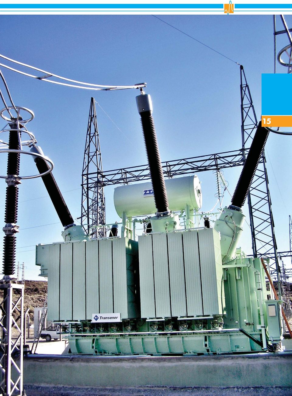
14 I. POWER TRANSFORMERS Òransformers for substations of transmission and distribution electric networks Transformers for substations of transmission electric networks are intended for the long-distance transmission of electric power at high voltage providing minimum electric losses in the transmission lines. Transformers for the substations of distribution electric networks are intended for electric power distribution between power consumers and for voltage decrease to the level of local distribution electric networks including industrial enterprises. Two- and three-winding transformers of this type as well as transformers with split winding are produced by ZTR. Almost all such transformers are equipped with in-built on-load tap changers.

15 Òàbl Transformers for substations of transmission and distribution electric networks Description Voltage, kv Rated capacity, MVA HV Rated voltage, kv LV Vector group Cooling Tap Changer Three phase two-winding 150 MVA, 525 kv ,5 YNd1 ONAF OLTC 63 MVA, 330 kv, LV split ,3-11,0 YNd11d11 OFAF OLTC 220 MVA, 220 kv ,0 YNd11 ONAF OLTC 160 MVA, 220 kv, LV split ,0 YNd11d11 OFAF OLTC 80 MVA, 220 kv, LV split ,3-11,0 YNd11d11 OFAF OLTC 63 MVA, 220 kv, LV split ,3; 10,5 YNd11d11 ONAF OLTC 63 MVA, 220 kv, LV split ,3-11,0 YNd11d11 OFAF OLTC 32 MVA, 220 kv, LV split ,3; 10,5 YNd11d11 ONAF OLTC 25 MVA, 220 kv ,5 YNd11 ONAF OLTC 5 MVA, 220 kv ,0 YNd11 ONAN OLTC 63 MVA, 150 kv, LV split ,3-11,0 YNd11d11 ONAF OLTC 32 MVA, 150 kv, LV split ,3; 10,5 YNd11d11 ONAF OLTC 16 MVA, 150 kv ,6; 11,0 YNd11 ONAF OLTC 125 MVA, 110 kv, LV split ,5 YNd11d11 OFAF OLTC 80 MVA, 110 kv, LV split ,3-11,0 YNd11d11 ONAF OLTC 80 MVA, 110 kv, LV split ,3-11,0 YNd11d11 OFAF OLTC 63 MVA, 110 kv ,0 YNd11 ONAF OLTC 63 MVA, 110 kv, LV split ,3-11,0 YNd11d11 ONAF OLTC 63 MVA, 110 kv, LV split ,3-11,0 YNd11d11 OFAF OLTC 63 MVA, 110 kv, LV split ,3-11,0 YNd11d11 ONAN OLTC 40 MVA, 110 kv ,6 YNd11 ONAF OLTC 40 MVA, 110 kv, LV split ,3-11,0 YNd11d11 ONAF OLTC 40 MVA, 110 kv, LV split ,3-11,0 YNd11d11 ONAN OLTC 32 MVA, 110 kv, LV split ,3; 10,5 YNd11d11 ONAF OLTC 25 MVA, 110 kv ,3; 10,5 YNd11 ONAF OLTC 25 MVA, 110 kv, LV split ,3-11,0 YNd11d11 ONAF OLTC 16 MVA, 110 kv ,6-34,5 YNd11 ONAF OLTC 10 MVA, 110 kv ,6-34,5 YNd11 ONAF OLTC 6,3 MVA, 110 kv 110 6, ,6; 11,0 YNd11 ONAN OLTC 2,5 MVA, 110 kv 110 2, ,6; 11,0 YNd11 ONAN OLTC 25 MVA, 66 kv ,6-24 Dyn1 ONAF OLTC 13

16 I. POWER TRANSFORMERS Continue Òàbl Transformers for substations of transmission and distribution electric networks Description Voltage, kv Rated apacity, MVA Rated voltage, kv HV MV LV Vector group Cooling Tap Changer Three phase three-winding MVA, 500 kv ,8; 34,5 YNyn0d11 ONAF OLTC 63 MVA, 220 kv ,0-38,5 6,6; 11,0 YNyn0d11; YNd11d11 ONAF OLTC (HV) OCTC (MV) 63 MVA, 220 kv ,0-38,5 6,6; 11,0 YNyn0d11; YNd11d11 OFAF OLTC (HV) OCTC (MV) 25 MVA, 220 kv ,0-38,5 6,6; 11,0 YNyn0d11; YNd11d11 ONAF OLTC (HV) OCTC (MV) 63 MVA, 150 kv ,0-38,5 6,6; 11,0 YNyn0d11; YNd11d11 ONAF OLTC (HV) OCTC (MV) 40 MVA, 150 kv ,0-38,5 6,6; 11,0 YNyn0d11; YNd11d11 ONAF OLTC (HV) OCTC (MV) 25 MVA, 150 kv ,0-38,5 6,6; 11,0 YNyn0d11; YNd11d11 ONAF OLTC (HV) OCTC (MV) 80 MVA, 110 kv ,0-38,5 6,6; 11,0 YNyn0d11; YNd11d11 ONAF OLTC 80 MVA, 110 kv ,0-38,5 6,6; 11,0 YNyn0d11; YNd11d11 OFAF OLTC 80 MVA, 110 kv, LV split ,0 YNyn0yn0+d+d OFAF OLTC 63 MVA, 110 kv ,0-38,5 6,6; 11,0 YNyn0d11; YNd11d11 ONAF OLTC (HV) OCTC (MV) 63 MVA, 110 kv ,0-38,5 6,6; 11,0 YNyn0d11; YNd11d11 OFAF OLTC (HV) OCTC (MV) 40 MVA, 110 kv ,0-38,5 6,6; 11,0 YNyn0d11; YNd11d11 ONAF OLTC (HV) OCTC (MV) 25 MVA, 110 kv ,0-38,5 6,6; 11,0 YNyn0d11; YNd11d11 ONAF OLTC (HV) OCTC (MV) 16 MVA, 110 kv ,0-38,5 6,6; 11,0 YNyn0d11; YNd11d11 ONAF OLTC (HV) OCTC (MV) 10 MVA, 110 kv ,0-38,5 6,6; 11,0 YNyn0d11; YNd11d11 ONAF OLTC (HV) OCTC (MV)
 OCTC (MV) 25 MVA, 220 kv 220 25 230 11,0-38,5 6,6; 11,0 YNyn0d11; YNd11d11 ONAF OLTC (HV) OCTC (MV) 63 MVA, 150 kv 150 63 158 11,0-38,5 6,6; 11,0")
17 15
18 I. POWER TRANSFORMERS Òàbl Transformers for substations of distribution networks up to 35 kv Description Voltage, kv Rated capacity, MVA Rated voltage, kv HV LV Vector group Cooling Tap Changer Three phase two-winding transformers 10 MVA, 35 kv ,75 6,3 YNd11 ONAN OLTC 16 6,3 MVA, 35 kv 35 6,3 35,0 6,3; 11,0 Yd11 ONAN OLTC 4 MVA, 35 kv ,0; 35,0 0,4-10,5 Yd11 ONAN OCTC 4 MVA, 35 kv ,0 6,3; 11,0 Yd11 ONAN OLTC 2,5 MVA, 35 kv 35 2,5 20,0; 35,0 0,4-10,5 Yd11 ONAN OCTC 2,5 MVA, 35 kv 35 2,5 13,8-35,0 6,3; 11,0 Yd11 ONAN OLTC 1,6 MVA, 35 kv 35 1,6 20,0; 35,0 0,4-10,5 Yyn0; Dyn11; Yd11 ONAN OCTC 1,6 MVA, 35 kv 35 1,6 13,8-35,0 0,4; 6,3; 11,0 Yyn0; Yd11 ONAN OLTC 1 MVA, 35 kv ,8-35,0 0,4-10,5 Yyn0; Dyn11; Yd11 ONAN OCTC 1 MVA, 35 kv ,0; 35,0 0,4; 6,3; 11,0 Yyn0; Yd11 ONAN OLTC 6,3 MVA, 20 kv 20 6,3 13,8-20,0 6,3; 11,0 Yd11 ONAN OLTC 4 MVA, 20 kv ,8-20,0 6,3; 11,0 Yd11 ONAN OLTC 20 MVA, 17 kv ,75; 17,0 6,3 Dyn11 ONAF OLTC 16 MVA, 16 kv ,5 YNd11 ONAF OCTC 10 MVA, 10 kv ,3 Yd11 ONAN OCTC 6,3 MVA, 10 kv 10 6,3 10,0 3,15-6,3 Yd11 ONAN OCTC 4 MVA, 10 kv ,0; 10,0 0,4-6,3 Yd11 ONAN OCTC 2,5 MVA, 10 kv 10 2,5 6,0; 10,0 0,4-6,3 Yd11 ONAN OCTC 2,5 MVA, 10 kv 10 2,5 6,0; 10,0 3,15; 6,3 Yd11 ONAN OLTC 1,6 MVA, 10 kv 10 1,6 6,0; 10,0 0,4-6,3 Yyn0; Dyn11; Yd11 ONAN OCTC 1 MVA, 10 kv ,0; 10,0 0,4-6,3 Yyn0; Dyn11; Yd11 ONAN OCTC 1 MVA, 10 kv ,0; 6,3; 10,0; 10,5 0,565 - ONAN OCTC 1 MVA, 10 kv ,0; 10,0 0,4 Dyn11; Yyn0 ANAN OCTC 1,6 MVA, 6 kv 6 1,6 6,0 0,4 Dyn11 ANAN OCTC 0,63 MVA, 6 kv 6 0,63 6,0 0,4 Dyn11 ANAN OCTC 0,4 MVA, 6 kv 6 0,4 6,0 0,4 Dyn11 ANAN OCTC

19 17

20 I. POWER TRANSFORMERS Auxiliary and standby transformers Two types of auxiliary transformers are produced by ZTR: generator transformers to be connected to the power plant generators, and standby transformers to be fed from highvoltage network. Standby transformers provide power plant with electricity during construction period as well as during operation in case of emergency shutoff of generators. As a rule both types of transformers are manufactured with split windings and on-load tap changers.

21 Òàbl. 4. Auxiliary and standby transformers Description Voltage, kv Rated capacity, MVA Rated voltage, kv HV LV Vector group Cooling Tap Changer Three phase two-winding transformers 63 MVA, 330 kv, LV split ,0 6,3-11,0 YNd11d11 ONAF OLTC 63 MVA, 220 kv, LV split ,0 6,3-11,0 YNd11d11 ONAF OLTC 63 MVA, 220 kv, LV split ,0 6,3 YNyn0yn0+d ONAF OLTC MVA, 220 kv, LV split ,0 6,3-11,0 YNd11d11 ONAF OLTC 63 MVA, 35 kv, LV split ,0-36,75 6,3; 10,5 YNd11d11; Dd0d0 ONAF OLTC 40 MVA, 35 kv, LV split ,75-36,75 6,3; 10,5 YNd11d11; Dd0d0 ONAF OLTC 40 MVA, 35 kv, LV split ,0 6,3 Dd0d0 ONAF OCTC 32 MVA, 35 kv, LV split ,75-36,75 6,3; 10,5 YNd11d11; Dd0d0 ONAF OLTC 25 MVA, 35 kv, LV split ,0; 20,0; 36,75 6,3 YNd11d11; Dd0d0 ONAF OLTC 16 MVA, 35 kv ,75 6,3; 10,5 YNd11 ONAF OLTC 10 MVA, 35 kv ,75 6,3 YNd11 ONAF OLTC 16 MVA, 20 kv ,5-18,0 6,3; 10,5 YNy0; Dd0 ONAF OLTC 25 MVA, 15 kv ,0 6,3 Dyn11 ONAF OLTC 25 MVA, 15 kv, LV split ,5; 15,75 6,3 Dd0d0 ONAF OLTC
22 I. POWER TRANSFORMERS Transformers for DC transmission lines and high-capacity converter substations of tie-lines ZTR product range also includes transformers for DC transmission lines and high-capacity converter substations of tie-lines; these transformers are intended for operation together with high-power HV converters (e.g. ± 400 or ± 750 kv), to be used either for rectification of AC or for inverse operation DC inversion. The specific feature of these transformers is ability to operate at DC high voltage effect as well as at nonsinusoidal currents. Particular requirement to these transformers is necessity to take into consideration design features of converting substation and choose optimal way of transformers connection to HV converting bridges. ZTR equipment design simplifies this connection a lot and, at the same time, provides its high reliability.
23 Òàbl. 5. Transformers for DC transmission lines and high-capacity converter substations of tie-lines Description Voltage, kv Rated capacity, MVA Rated voltage, kv HV LV Vector group Cooling Tap Changer Single phase two-winding transformers 320 MVA, ±750/500 kv / YNy11 (in 3-phase group) OFAF OLTC 175 MVA, ±750/500 kv / YNy11 (in 3-phase group) OFAF OLTC 320 MVA, ±400/500 kv / YNy11 (in 3-phase group) OFAF OLTC MVA, ±400/500 kv / YNy11 (in 3-phase group) OFAF OLTC Single phase three-winding transformers 135 MVA, 400/220 kv / YNd11 (in 3-phase group) OFAF OLTC 135 MVA, 400/110 kv / YNy0d11 (in 3-phase group) OFAF MVA, 330/110 kv / YNy0d11 (in 3-phase group) OFAF OLTC Three phase two-winding transformers 2 MVA, 10 kv ,0; 6,3; 10,0;10,5 0,565 ONAN OCTC
24 I. POWER TRANSFORMERS 6.1. Transformers for metallurgical enteprises 6. Special transformers: 22 Transformers for metallurgical enterprises manufactured by ZTR are intended for voltage decrease in the bus network kv to the level of metallurgical enterprises network (normally 35 kv) which feeds the transformers to be operated directly for furnace load. The special feature of such transformers is their ability to operate in the conditions of frequent switching on/off and load impacts Transformers for railway substations Transformers for railway substations manufactured by ZTR are intended for using at substations for voltage decrease in the bus network kv to voltage level of overhead contact system (normally 27 kv or 27.5 kv). The enterprises manufactures single-phase or three-phase, two-winding or three-winding transformers of this type. Three-phase threewinding transformers have one secondary winding used for power supply of overhead contact system and another secondary winding used for local public network 6-35 kv Line-regulating & phase-shifting transformers Line regulating transformers manufactured by ZTR are intended for voltage regulation in the networks 6-35 kv in such cases when required voltage level in this network could not be ensured by only existing in-built-in regulating transformers.
25 Òàbl Transformers for metallurgical enterprises Description Voltage, kv Rated capacity, MVA Rated voltage, kv HV LV Vector group Cooling Tap Changer Three phase two-winding transformers 160 MVA, 220 kv ,5 YNd11 OFAF OLTC 100 MVA, 220 kv, LV split ,5 YNd11d11 OFAF OCTC 100 MVA, 220 kv, LV split ,5 YNd11d11 OFAF OLTC 160 MVA, 110 kv ,0 YNd11 OFAF OLTC 80 MVA, 110 kv ,0 YNd11 OFAF OLTC 80 MVA, 110 kv, LV split ,5 YNd11d11 OFAF OLTC 23 Òàbl Transformers for railway substations Description Voltage, kv Rated capacity, MVA Rated voltage, kv HV MV LV Vector group Cooling Tap Changer Single phase three-winding railway transformers 25 MVA, 110 kv, LV split ,0 27,5 1/1/ ONAF OLTC Three phase three-winding railway transformers 40 MVA, 150 kv ,5 27,5 YNyn0d11 ONAF OLTC(HV), OCTC(MV) 40 MVA, 110 kv ,5; 38,5 6,6; 27,5 25 MVA, 110 kv ,5; 38,5 6,6; 27,5 YNyn0d11; YNd11d11 YNyn0d11; YNd11d11 ONAF ONAF OLTC(HV), OCTC (MV - 38,5êV) OLTC(HV), OCTC (MV - 38,5êV) Òàbl Line-regulating & phase-shifting transformers Description Voltage, kv Rated capacity, MVA Rated voltage, kv HV LV Cooling Tap Changer Three phase line-regulating transformers 63 MVA, 35 kv ,5 38,5 ONAF OLTC 63 MVA, 10 kv ,0 11,0 ONAF OLTC 40 MVA, ,0 11,0 ONAF OLTC MVA, 10 kv ,0 11,0 ONAN OLTC Three phase phase-shifting line-regulating transformers 400 MVA, 220 kv OFAF OLTC
26 I. POWER TRANSFORMERS 6.4. Furnace transformers Furnace transformers manufactured by ZTR are generally intended for ferroalloys and graphite production plants. 24 Essential feature of these transformers is advanced requirements to design which shall be capable to withstand numerous dynamic impacts caused by switchings Mine transformers Mine transformers manufactured by ZTR are intended for power supply to fixed coal mines and designed for the longterm operation in outdoor electric installations.
27 Òàáë Furnace transformers Description Voltage, kv Single phase two-winding transformers Rated capacity, MVA Rated voltage, kv HV LV Vector group Cooling Tap Changer 16 MVA, 10 kv ,204 1/1-0 OFAF OLTC 40 MVA, 150 kv / 3 0,24 1/1-0 OFAF OLTC Three phase two-winding transformers 160 MVA, 110 kv ,35 YNyn0d11 OFWF OLTC 25 12,5 MVA, 10 kv 10 12,5 10 0,204 YNyn0d11 OFWF OLTC 10 MVA, 10 kv ,204 YNyn0d11 OFWF OLTC 4 MVA, 10 kv ,204 YNyn0d11 OFAF OLTC 2,5 MVA, 10 kv 10 2,5 10 0,204 YNyn0d11 OFAF OLTC Òàbl Mine transformers Description Voltage, kv Rated capacity, MVA Rated voltage, kv HV MV LV Vector group Cooling Tap Changer Three phase three-winding transformers 40 MVA, 110 kv ,3 6,6 YNd11d11 ONAF OLTC(HV) 25 MVA, 110 kv ,3 6,6 YNd11d11 ONAF OLTC(HV) 16 MVA, 110 kv ,3 6,6 YNd11d11 ONAF OLTC(HV) 10 MVA, 110 kv ,3 6,6 YNd11d11 ONAF OLTC(HV) 10 MVA, 35 kv ,75 6,3 6,6 YNd11d11 ONAF OLTC(HV) Three phase two-winding transformers 6,3 MVA, 10 kv 10 6,3 6,0-6,3 Dd0 ONAN OCTC 4 MVA, 10 kv ,0-6,3 Yd11 ONAN OCTC 2,5 MVA, 10 kv 10 2,5 6,0-6,3 Yd11 ONAN OCTC
28 II. ELECTRICAL REACTORS Shunt reactors Shunt reactors manufactured by ZTR are intended for reactive power compensation in the transmission lines rated for voltage kv. Reactors allow increasing transfer capability of the transmission line, reducing electric power losses at its transformation, improving quality of electric power supplied to users. Basic model of shunt reactors has been elaborated considering experience of reactors operated in the power networks within 35 years. Design with core-type magnetic system with air-gaps core was chosen as a basic model being the most reliable, economical and in compliance with requirements.
29 Òàbl. 7. Shunt reactors Description Voltage, kv Rated capacity, MVA Rated voltage HV, kv Current, A Impedance, Ohm Vector group Cooling Tap Changer Single phase reactors 110 MVA, 750 kv / ONAN 60 MVA, 500 kv / ONAN 550 MVA, 400 kv / ONAN MVA, 35 kv 35 26, / ONAN Three phase reactors 128 MVA, 550 kv Óí ONAN 65 MVA, 550 kv Óí ONAN 60 MVA, 550 kv Óí ONAN 100 MVA, 400 kv Óí OFAF 50 MVA, 400 kv Óí ONAN 45 MVA, 400 kv Óí ONAN OCTC (400±2 2,5) 25 MVA, 230 kv Óí ONAN 50 MVA, 110 kv Óí ONAN 20 MVA, 35 kv , Óí ONAF 20 MVA, 35 kv , Óí ONAN 25 MVA, 20 kv Óí ONAN
30 II. ELECTRICAL REACTORS Neutral reactors Neutral reactors manufactured by ZTR are intended for current limiting to the earth in case of breakdown in the transmission line. As a rule, such reactors have no magnetic system, are equipped with electromagnetic shields arranged outside and on the end surfaces of winding. Winding insulation is of oil-barrier type. Cooling system is ONAN. Òàbl. 8. Neutral reactors Description Voltage, kv Rated capacity, MVA Rated voltage HV, kv Current, A Impedance, Ohm Cooling Tap Changer Earthing current-limiting reactors 16 MVAr, 35 kv ONAN 0,27 MVAr, 35 kv 35 0,270 35/ ONAN OCTC (300±4õ30) 0,51 MVAr, 26 kv 26 0,510 25, ONAN
31 29
32 30 III. CONTROLLABLE SHUNT REACTORS Controllable shunt reactor is a new type of FACTS (Flexible AC Transmission Systems) devices. It is a shunt-type static device with stepless regulation of inductive reactance. Controllable shunt reactors manufactured by ZTR are intended for automatic control over reactive power flows and stabilization of voltage levels that ensure the following: Elimination of daily and seasonal voltage oscillations in the electric network. Improvement of electric energy quality. Optimization and automation of the power network operating modes. Decrease losses of electric energy during power transmission and distribution. Improvement of operational conditions of electric equipment due to rapid step-down of switchings of nonregulated devices of reactive power compensation.
33 Increasing transfer capability of transmission lines and ensuring reliable automatic voltage control over voltage levels at power flows which are close to static stability limits. Elimination of voltage collapses in case of emergency conditions in the electric network (e.g., emergency powercut, shutdown of generator, line outages, etc.). 31 Providing operation conditions for power plant generators in such reactive power generation range which facilitates the most favorable operational duties. Òàbl. 10. Controllable shunt reactors Description Voltage, kv Rated capacity, MVA Rated voltage HV, kv Current, A Cooling Three phase bank formed of three phase electromagnetic unit reactors 180 MVA, 500 kv ONAF 180 MVA, 330 kv OFAF/ONAF 100 MVA, 220 kv ONAF 25 MVA, 220kV ONAF 25 MVA, 110kV ONAF 63 MVA, 110 kv ONAF 25 MVA, 35kV ,5 375 ONAF Three phase bank formed of single phase electromagnetic units reactors 180 MVAr, 500 kv ONAF
34 32 JSC «ZAPOROZHTRANSFORMATOR» 3, Dnepropetrovskoe shosse, Zaporozhye, 69600, Ukraine tel fax Sales Department tel fax FOR SUPPLIES OUTSIDE CIS COUNTRIES ZTR-ENESTA Handelsgesellschaft m.b.h. Joint Venture between ZTR and VAIT Strasserau 6, A-4010, Linz, Austria tel.: fax: [email protected] REPRESENTATIVE OFFICE IN THE REPUBLIC OF KAZAKHSTAN AND MIDDLE ASIA Office 701, 151/115, Abaya Avenue, Business centre Alatau, , Almaty, Republic of Kazakhstan Tel. +7 (727) Fax: +7 (727) [email protected] REPRESENTATIVE OFFICES IN THE RUSSIAN FEDERATION MOSCOW build. 1, 17/2 Bolshaya Yakimanka str Moscow, Russian Federation Tel.: +7 (495) , Fax: +7 (495) [email protected] ST.PETERSBURG office 409, 5 Krapivniy side str St. Petersburg, Russian Federation Tel.: +7 (812) Fax: +7 (812) EKATERINBURG office 410, 22 Karl Libkneht str Ekaterinburg, Russian Federation Tel./Fax: +7 (343) KRASNOYARSK Office 309, 110 Dubrovinskogo str Krasnoyarsk, Russian Federation Tel.: +7 (3912) Fax: +7 (3912) KRASNODAR Office 409, 135/1 Turgeneva str Krasnodar, Russian Federation Tel.: +7 (861) Fax.: +7 (861)
35
36
Transformers. Special transformers Reactors products
 Transformers Special transformers Reactors products Reactors Custom designed, custom built ABB Oy Transformers has extensive experience and numerous references from different reactor applications, having
Power Transmission and Distribution. Shunt reactors for medium and highvoltage. From development to use
 Power Transmission and Distribution Shunt reactors for medium and highvoltage networks: From development to use From the beginning up to today more quality and reliability for your network A safe power
Technical Information Requirement for MV transformers and transformer for internal power supplies for SUNNY CENTRAL
 Technical Information Requirement for MV transformers and transformer for internal power supplies for SUNNY CENTRAL SC_Trafo-TI-en-62 Version 6.2 ENGLISH Table of Contents SMA Solar Technology Table of
Power transformers. Special transformers Railway
 Power transformers Special transformers Railway A leader in railway systems Our compact and low-weight transformers fully comply with the customer s specifications. The products are developed together
Transformer Design & Design Parameters
 Transformer Design & Design Parameters - Ronnie Minhaz, P.Eng. Power Transmission + Distribution GENERATION TRANSMISSION SUB-TRANSMISSION DISTRIBUTION DISTRIBUTED POWER 115/10 or 20 kv 500/230 230/13.8
Power Technology Issue 106. Modeling of Three-Winding Voltage Regulating Transformers for Positive Sequence Load Flow Analysis in PSS E
 SIEMENS Siemens Energy, Inc. Power Technology Issue 106 Modeling of Three-Winding Voltage Regulating Transformers for Positive Sequence Load Flow Analysis in PSS E Carlos Grande-Moran, Ph.D. Principal
Power Technology Issue 104. Modeling of Two-Winding Voltage Regulating Transformers for Positive Sequence Load Flow Analysis in PSS E
 SIEMENS Siemens Energy, Inc. Power Technology Issue 104 Modeling of TwoWinding Voltage Regulating Transformers for Positive Sequence Load Flow Analysis in PSS E Carlos GrandeMoran, Ph.D. Principal Consultant
Power Voltage Transformers for Air Insulated Substations. THE PROVEN POWER.
 Power Voltage Transformers for Air Insulated Substations THE PROVEN POWER. Introduction Trench Power Voltage Transformers (Power VTs) combine the attributes of an inductive voltage transformer with the
EMTP STUDIES PERFORMED TO INSERT LONG AC CABLES IN THE FRENCH GRID
 Tension (kv) Impedance (Ohms) EMTP STUDIES PERFORMED TO INSERT LONG AC CABLES IN THE FRENCH GRID frequency (Hz) Simon DESCHANVRES Yannick VERNAY RTE, CNER, Substations Department t (ms) EMTP-RV Users Group
TYPE TEST CERTIFICATE OF SHORT-CIRCUIT PERFORMANCE. A three-phase outdoor oil-immersed distribution transformer
 168-08 TYPE TEST CERTIFICATE OF SHORT-CIRCUIT PERFORMANCE APPARATUS A three-phase outdoor oil-immersed distribution transformer DESIGNATION 1000 kva SERIAL No. 1-08-112-01-0001 Rated power Rated voltage
Practical Transformers: Operation, Maintenance and Testing
 Practical Transformers: Operation, Maintenance and Testing YOU WILL GAIN: 4 hour live, practical online course Saturday, 2 nd May, 2015 8.00AM WST; 10.00AM AEST An understanding of the fundamental theory
Medium-voltage Transformers
 Technical Information Medium-voltage Transformers Important requirements for medium-voltage transformers for SUNNY BOY, SUNNY MINI CENTRAL and SUNNY TRIPOWER Contents This document describes the requirements
EFFICIENT ELECTRICAL ENERGY TRANSMISSION AND DISTRIBUTION INTERNATIONAL ELECTROTECHNICAL COMMISSION
 EFFICIENT ELECTRICAL ENERGY TRANSMISSION AND DISTRIBUTION INTERNATIONAL ELECTROTECHNICAL COMMISSION EFFICIENT ELECTRICAL ENERGY TRANSMISSION AND DISTRIBUTION 1 EFFICIENT ELECTRICAL ENERGY TRANSMISSION
Requirements for Offshore Grid Connections. in the. Grid of TenneT TSO GmbH
 Requirements for Offshore Grid Connections in the Grid of TenneT TSO GmbH Bernecker Straße 70, 95448 Bayreuth Updated: 21 December 2012 1/10 Requirements for Offshore Grid Connections in the Grid of TenneT
How To Understand The Electrical Power Supply Of A Power Supply System
 17 Circuit diagram symbols E 18 CIRCUIT DIAGRAM SYMBOLS electrical network elements three-phase line or cable single-phase line or cable short circuit earth electrode outgoing feeder supply incoming feeder
MEDIUM AND HIGH VOLTAGE CAPACITORS, CAPACITOR BANKS AND SYSTEMS
 MEDIUM AND HIGH VOLTAGE CAPACITORS, CAPACITOR BANKS AND SYSTEMS Meher Capacitors offers reliable and innovative products and solutions in the fields of Reactive Power Compensation, Power Quality and Energy
Tamini is the leading Italian company in the world for the design and production of industrial, power and special transformers.
 Industrial Tamini is the leading Italian company in the world for the design and production of industrial, power and special transformers. Founded in 1916 in Milan, it supplies its products to the most
Knowing the FACTS. FACTS that enhance power quality in rail feeder systems
 Knowing the FACTS FACTS that enhance power quality in rail feeder systems ROLF GRÜNBAUM, PER HALVARSSON, BJÖRN THORVALDSSON The increase in traffic on existing tracks combined with new high-speed rail
Presentation to CIGRE Next Generation Network. Visit of Seine substation
 Presentation to CIGRE Next Generation Network Visit of Seine substation Projet Seine 30 août 2012 Contents 0. Presentation of RTE 1. Power supply of «Ile-de-France» and Paris 2. 225 kv Paris substations
Three Gorges - Changzhou HVDC : Ready to Bring Bulk Power to East
 The 4 th International Conference on Power Transmission & Distribution Technology 2003 14-16 October, 2003, Changsha 2003 Three Gorges - Changzhou HVDC : Ready to Bring Bulk Power to East Abhay Kumar Mats
INTERNATIONAL STANDARD
 INTENATIONAL STANDAD IEC 60076-1 Edition 2.1 2000-04 Edition 2:1993 consolidated with amendment 1:1999 Power transformers Part 1: General This English-language version is derived from the original bilingual
For a phase-to-phase voltage between 100 V and 1000 V. The standard ratings are: 400 V - 690 V - 1000 V (at 50 Hz)
") 24 1. NETWORK CONFIGURATIONS definition Standard IEC 38 defines voltage ratings as follows: - Low voltage () For a phase-to-phase voltage between 100 V and 1000 V. The standard ratings are: 400 V - 690
24 1. NETWORK CONFIGURATIONS definition Standard IEC 38 defines voltage ratings as follows: - Low voltage () For a phase-to-phase voltage between 100 V and 1000 V. The standard ratings are: 400 V - 690
ANCILLARY EQUIPMENT AND ELECTRICAL EQUIPMENT Power Supply Systems and Electrical Equipment for Desalination Plants - Y.M. Hamud and A.H.
 POWER SUPPLY SYSTEMS AND ELECTRICAL EQUIPMENT FOR DESALINATION PLANTS Y.M. Hamud and A.H. Anwar Abu Dhabi Water and Electricity Authority, Abu Dhabi, UAE Keywords : Electrical System, Network for Desalination,
Fundamentals of Modern Electrical Substations Part 1: Mission of Electrical Substations and their Main Components
 Fundamentals of Modern Electrical Substations Part 1: Mission of Electrical Substations and their Main Components Course No: E02-010 Credit: 2 PDH Boris Shvartsberg, Ph.D., P.E., P.M.P. Continuing Education
Unified requirements for systems with voltages above 1 kv up to 15 kv
 (1991) (Rev.1 May 2001) (Rev.2 July 2003) (Rev.3 Feb 2015) Unified requirements for systems with voltages above 1 kv up to 15 kv 1. General 1.1 Field of application The following requirements apply to
INTERNATIONAL STANDARD
 INTERNATIONAL STANDARD IEC 60076-11 First edition 2004-05 Power transformers Part 11: Dry-type transformers This English-language version is derived from the original bilingual publication by leaving out
Capacitor Voltage Transformer. Answers for energy.
 Capacitor Voltage Transformer Answers for energy. Capacitor Voltage Transformer Siemens Capacitor Voltage Transformers are based on technology from Trench, a recognized world leader in the design and manufacture
ESB Networks Response. ERGEG Consultation. Voltage Quality Regulation in Europe
 NETWORKS ESB Networks Response to ERGEG Consultation on Voltage Quality Regulation in Europe Date: 22 February 2007 Distribution System Operator ESB Networks Page 1 of 12 Contents 1.0 INTRODUCTION...3
LAB1 INTRODUCTION TO PSS/E EE 461 Power Systems Colorado State University
 LAB1 INTRODUCTION TO PSS/E EE 461 Power Systems Colorado State University PURPOSE: The purpose of this lab is to introduce PSS/E. This lab will introduce the following aspects of PSS/E: Introduction to
INTERNATIONAL JOURNAL OF ELECTRICAL ENGINEERING & TECHNOLOGY (IJEET)
") INTERNATIONAL JOURNAL OF ELECTRICAL ENGINEERING & TECHNOLOGY (IJEET) International Journal of Electrical Engineering and Technology (IJEET), ISSN 0976 ISSN 0976 6545(Print) ISSN 0976 6553(Online) Volume
INTERNATIONAL JOURNAL OF ELECTRICAL ENGINEERING & TECHNOLOGY (IJEET) International Journal of Electrical Engineering and Technology (IJEET), ISSN 0976 ISSN 0976 6545(Print) ISSN 0976 6553(Online) Volume
Table of Contents. TransformerIQ FAQs 1
 [12/12] FAQs Table of Contents FAQ 1. What size transformer will TransformerIQ monitor?... 2 FAQ 2. Are there different TransformerIQ versions?... 2 FAQ 3. How are the units powered?... 2 FAQ 4. What is
MINISTERIE VAN ECONOMISCHE ZAKEN GENERAL COST COMPARISON BETWEEN UNDERGROUND CABLES AND O.H. LINE SYSTEMS FOR H.V. TRANSMISSION
 MINISTERIE VAN ECONOMISCHE ZAKEN GENERAL COST COMPARISON BETWEEN UNDERGROUND CABLES AND O.H. LINE SYSTEMS FOR H.V. TRANSMISSION REPORT ON NETWORK RELIABILITY ASPECTS OF THE CHOICE LINE VERSUS CABLE FOR
General Validation Test Program for Wind Power Plants Connected to the Hydro-Québec Transmission System
 General Validation Test Program for Wind Power Plants Connected to the Hydro-Québec Transmission System Direction Planification des actifs et expertise de transport February 2011 TABLE OF CONTENTS 1. CONDUCTING
Step Voltage Regulators
 Step Voltage Regulators Don Wareham Field Application Engineer Today s Agenda Introduction Voltage Regulator theory Voltage Regulator application considerations Installation and proper bypassing Wrap-up/questions
COMPARISON OF THE FACTS EQUIPMENT OPERATION IN TRANSMISSION AND DISTRIBUTION SYSTEMS
 COMPARISON OF THE FACTS EQUIPMENT OPERATION IN TRANSMISSION AND DISTRIBUTION SYSTEMS Afshin LASHKAR ARA Azad University of Dezfoul - Iran [email protected] Seyed Ali NABAVI NIAKI University of Mazandaran
Basic Load Tap Changer Operation
 Basic Load Tap Changer Operation Topics Basic Transformer Theory Differences from LTC s to DETC s LTC Definitions Transformer Nameplates Purpose of a Tap Changer How Does an LTC Work? Topics Reactance
Single and Three Phase Transformer Testing Using Static Motor Circuit Analysis Techniques
 Single and Three Phase Transformer Testing Using Static Motor Circuit Analysis Techniques Howard W. Penrose, Ph.D On behalf of ALL-TEST Pro, LLC Old Saybrook, CT Introduction Field and shop testing of
CO-ORDINATION OF PARALLEL AC-DC SYSTEMS FOR OPTIMUM PERFORMANCE
 CO-ORDINATION OF PARALLEL AC-DC SYSTEMS FOR OPTIMUM PERFORMANCE Ana Diez Castro & Rickard Ellström Ying Jiang Häfner Christer Liljegren Vattenfall Utveckling AB ABB Power Systems Gotlands Energiverk AB
DRY TYPE TRANSFORMER
 PRODUCT LEAFLET DRY TYPE TRANSFORMER Single-phase, three-single, three-two and three-phase transformers 1.1 kv to 7.2 kv classes 1 60 40152-13/09/2011 Dry Type Transformers Transformers meant to be installed
CONSULTATION PAPER FOR PROPOSED MODIFICATIONS TO THE TRANSMISSION CODE
 CONSULTATION PAPER FOR PROPOSED MODIFICATIONS TO THE TRANSMISSION CODE Closing date for submission of representations: 30 th Sep 2014, 5 pm 18 AUG 2014 ENERGY MARKET AUTHORITY 991G Alexandra Road #01-29
Electric Power Systems An Overview. Y. Baghzouz Professor of Electrical Engineering University of Nevada, Las Vegas
 Electric Power Systems An Overview Y. Baghzouz Professor of Electrical Engineering University of Nevada, Las Vegas Overview Power Generation Conventional power generation Power generation from renewables
ELECTRICAL ENGINEERING DESIGN CRITERIA APPENDIX F
 ELECTRICAL ENGINEERING DESIGN CRITERIA APPENDIX F TABLE OF CONTENTS Appendix F - Electrical Engineering Design Criteria F.1 Introduction...F-1 F.2 Codes and Standards...F-1 F.3 Switchyard and Transformers...F-1
Power Transformer Fundamentals: Design and Manufacturing
 Power Transformer Fundamentals: Design and Manufacturing Waldemar Ziomek, Engineering Manager CG Power Systems Canada Inc IEEE Training, Houston, Texas, Oct.8-9, 2013 1 Overview Transformer Design Transformer
INTERNATIONAL STANDARD
 INTERNATIONAL STANDARD IEC 60076-1 Edition 2.1 2000-04 Edition 2:1993 consolidated with amendment 1:1999 Power transformers Part 1: General This English-language version is derived from the original bilingual
HVDC Technology for Large Scale Offshore Wind Connections
 HVDC Technology for Large Scale Offshore Wind Connections Nandan Mahimkar, Gunnar Persson,Claes Westerlind, ABB AB, SE-771 80, Ludvika, Sweden, [email protected], [email protected],[email protected],
Differential Protection for Arbitrary Three-Phase Power Transformers
 Differential Protection for Arbitrary Three-Phase Power Transformers Zoran Gajić Doctoral Dissertation Department of Industrial Electrical Engineering and Automation 28 i Department of Industrial Electrical
AMSC s Superconductor Cable Technologies for Electric Utilities
 International Workshop 2014 AMSC s Superconductor Cable Technologies for Electric Utilities Michael Ross, P.E. Managing Director of Superconductor Power Systems AMSC Corporate Facts Headquartered in MA,
Earthing Guidance Notes
 Central Networks Earthing Manual Section E2 Earthing Guidance Notes Version: 2 Date of Issue: September 2007 Author: Nigel Johnson Job Title: Earthing Specialist Approver: John Simpson Job Title: Head
232 Siemens Energy Sector Power Engineering Guide Edition 7.0
 232 .1 Introduction 234 Transformers.1.1 Overview 234.2 Reliability and Project Performance 236.3 Transformer Loss Evaluation 238.4 Power Transformers 240.4.1 Large Power Transformers 240.4.2 Medium Power
The design and performance of Static Var Compensators for particle accelerators
 CERN-ACC-2015-0104 [email protected] The design and performance of Static Var Compensators for particle accelerators Karsten Kahle, Francisco R. Blánquez, Charles-Mathieu Genton CERN, Geneva, Switzerland,
Power Transformers 10 to 100 MVA
 Power Transformers 10 to 100 MVA Transformer technology at a glance An extensive transmission system with efficient transformers is indispensable to ensure a reliable supply of power. Consequently Siemens
Technology for electrical energy efficiency
 Technology for electrical energy efficiency The leader in electrical energy efficiency Leading company in electric energy control More than 35 years experience and constant evolution are the best guarantee
Presentation of the France Transfo factories
 Presentation of the France Transfo factories France Transfo's internationally recognised and highly esteemed expertise is today exported to more than 80 countries throughout the world. Over the past 15
MOHAMMAD KHORAMI. Examiner: Dr. Anh Tuan Le Senior Lecturer, Electric Power Engineering, Chalmers University of Technology. Master of Science Thesis
 Application Fields and Control Principles of Variable Shunt Reactors with Tap-Changer Investigation of Possible Control Strategies of Variable Shunt Reactors through Simulation of a Power System under
IEC PROJETOS EM VOTAÇÃO JULHO E AGOSTO. IEC 60034-1 Ed.13: Rotating electrical machines - Part 1: Rating and performance.
 IEC PROJETOS EM VOTAÇÃO JULHO E AGOSTO IEC/TC 2 - Rotating machinery IEC 60034-1 Ed.13: Rotating electrical machines - Part 1: Rating and performance. IEC 60034-12 Ed.3: Rotating electrical machines -
SIMULATING HYBRID ENERGY GRIDS IN SMART CITIES FOCUS ON ELECTRIC ENERGY SYSTEMS
 Sawsan Henein AIT Austrian Institute of Technology Electric Energy Systems Research Group SIMULATING HYBRID ENERGY GRIDS IN SMART CITIES FOCUS ON ELECTRIC ENERGY SYSTEMS Sustainable Places 2015 Savona,
Mechanical and electrical rebuilding of a turbine generator for phase-shift operation
 www.siemens.com/energy Mechanical and electrical rebuilding of a turbine generator for phase-shift operation POWER-GEN Europe 2013 Vienna, Austria June 04-06, 2013 Authors: Detlef Frerichs Anastassios
Reactive Power and Importance to Bulk Power System OAK RIDGE NATIONAL LABORATORY ENGINEERING SCIENCE & TECHNOLOGY DIVISION
 Reactive Power and Importance to Bulk Power System OAK RIDGE NATIONAL LABORATORY ENGINEERING SCIENCE & TECHNOLOGY DIVISION Outline What is Reactive Power and where does it come from? Why is it important?
Voltage Regulator SPAU 341 C. Product Guide
 Issued: July 1998 Status: Updated Version: D/25.04.2006 Data subject to change without notice Features Comprehensive voltage regulation for power transformers with on-load tapchangers in distribution substations
Transformers Energy efficient transformer solutions European Minimum Energy Performance Standard (MEPS)
") Transformers Energy efficient transformer solutions European Minimum Energy Performance Standard (MEPS) 2 European MEPS for transformers The EU MEPS (European Minimum Energy Performance Standard) Transformers
Transformers Energy efficient transformer solutions European Minimum Energy Performance Standard (MEPS) 2 European MEPS for transformers The EU MEPS (European Minimum Energy Performance Standard) Transformers
7. Reactive energy compensation
 593 7. Reactive energy compensation 594 7. REACTIVE ENERGY COMPENSATION Reactive energy compensation is an important element for reducing the electricity bill and improving the quality of the electrical
The stable way. Synchronous condenser solutions. siemens.com/energy/facts
 The stable way Synchronous condenser solutions siemens.com/energy/facts Bringing grids in line with new requirements Global climate change poses new challenges for power generation and transmission. Innovative
TRACTION NETWORK MONITORING AND PROTECTION SYSTEM SMTN-3 CITY ELECTRIC TRANSPORT RAILWAYS METRO INDUSTRY
 TRACTION NETWORK MONITORING AND PROTECTION SYSTEM SMTN-3 CITY ELECTRIC TRANSPORT RAILWAYS METRO INDUSTRY 2 TRACTION NETWORK MONITORING AND PROTECTION SYSTEM Traction network monitoring and protection system,
Circulating Current Relay. Type IRXm
 Circulating Current Relay Type IRXm ABB a global technology leader ABB is a global leader in Power and Automation technologies that enable utility and industry customers to improve performance while lowering
Voltage regulation in distribution systems - Tap changer and Wind Power
 CODEN:LUTEDX/(TEIE-5270)/1-59/(2010) Industrial Electrical Engineering and Automation Voltage regulation in distribution systems - Tap changer and Wind Power David Sáez Romero D of Industrial Electrical
A Guide to Transformer Winding Resistance Measurements
 Application Information 1 (20) A Guide to Transformer Winding Resistance Measurements Bruce Hembroff, CET, Manitoba Hydro, Megger Sweden, Megger Sweden Abstract: Measuring a transformer's DC resistance
Current and voltage measuring relays
 Current and voltage measuring relays RXIK 1, RXEEB 1 and Page 1 Issued June 1999 Changed since July 1998 Data subject to change without notice RXIK 1 RXEEB 1 (SE980082) (SE980081) (SE970869) Features Application
The electrical energy produced at the gen
 300 300 Principles of Power System CHAPTER CHAPTER 12 Distribution Systems General 12.1 Distribution System 12.2 Classification of Distribution Systems 12.3 A.C. Distribution 12.4 D.C. Distribution 12.5
CAPACITOR BANK TESTING SWP
 1. PURPOSE AND SCOPE The purpose of this Standard Work Practice (SWP) is to standardise and prescribe the method for testing Capacitor Banks including capacitors, tuning reactors and inrush limiting reactors.
2013 RESIBLOC transformers Product presentation. ABB Group October 2, 2013 Slide 1
 2013 RESIBLOC transformers Product presentation October 2, 2013 Slide 1 Dry-type transformers For customers with high requirements Does your transformer application requires one of the following characteristic?
Controlled subsea electric power distribution with SEPDIS
 Controlled subsea electric power distribution with SEPDIS Nils Arne Sølvik, Jan Ove Gjerde, Trond Skullerud Unlike the first generation of offshore systems, which were designed to operate on platforms
WINDING RESISTANCE TESTING
 WINDING RESISTANCE TESTING WINDING RESISTANCE TEST SET, MODEL WRT-100 ADWEL INTERNATIONAL LTD. 60 Ironside Crescent, Unit 9 Scarborough, Ontario, Canada M1X 1G4 Telephone: (416) 321-1988 Fax: (416) 321-1991
Application of On-line Monitoring Systems in the view of Maintenance Engineering of Eletrobras Furnas
 1 Application of On-line Monitoring Systems in the view of Maintenance Engineering of Eletrobras Furnas Fabio Abreu Pinto, Eletrobras Furnas, Jorge Santelli da Silva, Eletrobras Furnas, and Marcos E. G.
VOLTAGE CONTROL IN DISTRIBUTION SYSTEMS AS A LIMITATION OF THE HOSTING CAPACITY FOR DISTRIBUTED ENERGY RESOURCES
 VOLTAGE CONTROL IN DISTRIBUTION SYSTEMS AS A LIMITATION OF THE HOSTING CAPACITY FOR DISTRIBUTED ENERGY RESOURCES C. Schwaegerl*, M.H.J. Bollen, K. Karoui #, A. Yagmur + *Siemens AG, # Tractebel STRI AB
ES281 COMPANY-SPECIFIC APPENDICES TO ENA ENGINEERING RECOMMENDATION G81 PART 1
 ES281 COMPANY-SPECIFIC APPENDICES TO ENA ENGINEERING RECOMMENDATION G81 PART 1 Design and Planning Specification for New Low Voltage Installations for Housing Developments 1. SCOPE This appendix to ENA
Superconducting and Solid-State Electronic Fault Current Limiter Technologies The shift from demonstration projects to Business-as-Usual solutions
 Superconducting and Solid-State Electronic Fault Current Limiter Technologies The shift from demonstration projects to Business-as-Usual solutions Dr. Detlev Kirsten & Herbert Piereder Solid State SSFCL
Modeling and Testing of Unbalanced Loading and Voltage Regulation
 National Renewable Energy Laboratory Innovation for Our Energy Future A national laboratory of the U.S. Department of Energy Office of Energy Efficiency & Renewable Energy Modeling and Testing of Unbalanced
FACTS. Solutions to optimise network performance GRID
 Solutions to optimise network performance GRID Solutions to optimise your network Our worldwide presence: Better solutions for your network all around the world Tampere Philadelphia Stafford Konstanz Beijing
Automated test systems for distribution transformers Part II. Detailed analysis of the test system features EVENTS ABSTRACT KEYWORDS
 TESTS EVENTS ABSTRACT Distribution transformers are used worldwide and in very large quantities as a link between regional mediumvoltage networks and local low-volt age distribution systems. To ensure
INTERNATIONAL STANDARD
 INTERNATIONAL STANDARD IEC 60071-2 Third edition 1996-12 Insulation co-ordination Part 2: Application guide This English-language version is derived from the original bilingual publication by leaving out
Protection of a Three- Winding Transformer
 Protection of a Three- Winding Transformer Three-winding transformer 110 kv/25 kv/10 kv Yyn0d5 25 kv-side: Solidly earthed Protection functions ANSI 87 T - Differential protection ANSI 87 N - Earth-fault
Appendix 7. Conceptual Design of Electrification System. December 2010
 Appendix 7 Conceptual Design of Electrification System December 2010 APPENDIX 7 Conceptual Design of Electrification System December 2010 Prepared for: Prepared by: 20 Bay Street, Suite 901 Toronto ON
SHORT CIRCUIT CURRENT CALCULATION AND PREVENTION IN HIGH VOLTAGE POWER NETS
 Bachelor's Thesis Electrical Engineering June 2014 SHORT CIRCUIT CURRENT CALCULATION AND PREVENTION IN HIGH VOLTAGE POWER NETS MD FARUQUL ALAM SALMAN SAIF HAMID ALI School of Engineering Blekinge Tekniska
Federal Wage System Job Grading Standards for Electric Power Controlling, 5407. Table of Contents
 Federal Wage System Job Grading Standards for Electric Power Controlling, 5407 Table of Contents WORK COVERED... 2 WORK NOT COVERED...2 TITLES... 2 GRADE LEVELS... 2 SPECIAL ADDITIONAL RESPONSIBILITIES...
MODELING AND TESTING OF UNBALANCED LOADING AND VOLTAGE REGULATION. Prepared For: California Energy Commission Public Interest Energy Research Program
 PIER FINAL PROJECT REPORT MODELING AND TESTING OF UNBALANCED LOADING AND VOLTAGE REGULATION Arnold Schwarzenegger Governor Prepared For: California Energy Commission Public Interest Energy Research Program
Assessment of the Technical Issues relating to Significant Amounts of EHV Underground Cable in the All-island Electricity Transmission System
 Assessment of the Technical Issues relating to Significant Amounts of EHV Underground Cable in the All-island Electricity Transmission System Summary Report November 2009 Technical Report on using EHV
Instrument Transformers Application Guide
 Instrument Transformers Application Guide Edited by ABB AB High Voltage Products Department: Marketing & Sales Text: Knut Sjövall, ABB Layout, 3D and images: Mats Findell, ABB SE-771 80 LUDVIKA, Sweden
Short Circuit Current Calculations
 Introduction Several sections of the National Electrical Code relate to proper overcurrent protection. Safe and reliable application of overcurrent protective devices based on these sections mandate that
Distribution Design Manual
 1 6 DESIGN PARAMETERS 4 6.1 Glossary and Definitions 4 6.2 Standard Voltages and Frequency 5 6.2.1 Transmission 5 6.2.2 Subtransmission 6 6.2.3 MV Distribution 6 6.2.4 LV Distribution 7 6.3 Point of Supply
ENDOKS ENERGY SYSTEMS POWER QUALITY PROJECTS REFERENCE LIST
 ENDOKS ENERGY SYSTEMS POWER QUALITY PROJECTS REFERENCE LIST January, 2012 SVC PROJECTS 1. AKDAŞ LF and IF 34.5 kv 12 MVAr 2012 AKDAŞ Döküm A.Ş. 12 MVAr TCR, 3 MVAr 3 rd HF, 5.5 MVAr 5 th HF, 3.5 MVAr 7
T 3000. Substation Maintenance and Commissioning Test Equipment
 T 3000 Substation Maintenance and Commissioning Test Equipment Multi function system for testing substation equipment such as: current, voltage and power transformers, all type of protection relays, energy
Product Data Bulletin
 Product Data Bulletin Power System Harmonics Causes and Effects of Variable Frequency Drives Relative to the IEEE 519-1992 Standard Raleigh, NC, U.S.A. INTRODUCTION This document describes power system
Harmonic components: electrical network polluters. LV and MV networks are becoming increasingly polluted by current and voltage harmonics. Harmonics a
 Harmonics and transformers Harmonic component filter Harmonic components: electrical network polluters. LV and MV networks are becoming increasingly polluted by current and voltage harmonics. Harmonics
TRANSFORMER: THREE PHASE
 CONTENTS Transformer : Three Phase 1211 C H A P T E R 33 Learning Objectives Three-phase Transformers Three-phase Transformer Connections Star/Star or Y/Y Connection Delta-Delta or Connection Wye/Delta
vacon ac drives for mining & minerals
 vacon ac drives for mining & minerals 1 strong experience in mining & minerals Vacon AC drives are robust to handle your most demanding requirements from simple ventilation to the most complex load sharing
HVDC Light, a tool for electric power transmission to distant loads
 Presented at VI Sepope Conference, Salvador, Brazil, May 1998 HVDC Light, a tool for electric power transmission to distant loads by Gunnar Asplund Kjell Eriksson* Ove Tollerz ABB Power Systems AB ABB
Discussion on Class I & II Terminology. IEEE PES Transformers Committee Fall Meeting 2011 Boston, MA
 Discussion on Class I & II Terminology IEEE PES Transformers Committee Fall Meeting 2011 Boston, MA What is Class I & II? C57.12.00 2010 is the only document we have that defined these terms. 5.10 Insulation
Emirates Aluminium starts up World s first fully integrated power distribution system from ABB
 Reprint from Aluminium World 2009, Volume 2 Emirates Aluminium starts up World s first fully integrated power distribution system from ABB Emirates Aluminium (EMAL), a joint venture between Abu Dhabi s