Don Lancaster's Active Filter Cookbook
|
|
|
- Barnaby Bridges
- 4 years ago
- Views:
Transcription


1 Don Lancaster's Active Filter Cookbook I Your definitive resource for the use and understanding of inductorless lowpass, bandpass, and high pass opamp resident electronic filters.
2 Active-Filter Cookbook by Don Lancaster
3 SECOND EDITION SEVENTEENTH PRINTINC-1995 Copyright 1975, 1995 by Don Lancaster and Synergetics, Thatcher Arizona. All rights reserved. Reproduction or use, without express permission, of editorial or pictorial content, in any manner, is prohibited. No patent liability is assumed with respect to the use of the information that is contained herein. Although every precaution has been taken in the preparation of this book, the publisher assumes no responsibility for errors or omissions. Neither is any liability assumed for damages resulting from the use of the information contained herein. International Standard Book Number:
4
5 Chapter 2 tells all about operational amplifiers, particularly the circuits needed for active filters, and has a mini-catalog of suitable commercial devices. The basic properties of the five elemental first- and second-order building blocks appear in Chapter 3. Complete response curves that help us decide how much of a filter is needed for a certain job are the subjects of Chapters 4 and 5. The high-pass and low-pass curves of Chapter 4 cover seven different shape options through six orders of filter. The shape options represent a continuum from a Bessel, or best-time-delay, filter through a flattest-amplitude, or Butterworth, filter through various Chebyshev responses of slight, 1-, 2-, and 3-dB dips. The bandpass curves of Chapter 5 show us exactly what the response shape will be, again through the sixth order with five shape options. This chapter introduces a simple technique called cascaded-pole synthesis that greatly simplifies the design of active bandpass filters and gives you absolutely complete and well-defined response curves. Actual filter circuits appear in Chapters 6 through 8. Four different styles of low-pass, bandpass, and high-pass circuits are shown. Low-pass and high-pass circuits include the simple and easily tuneable Sallen-Key styles, along with the multiple IC state-variable circuits. Bandpass versions include a single op-amp multiple-feedback circuit for moderate Qs and state-variable and biquad circuits circuits for Qs as high as several hundred. Chapter 9 shows us how to perform switching, tuning, and voltage control of active filters. It also looks at some fancier filter concepts such as allpass networks and bandstop filters and finally ends up with a very high performance ultimate-response filter called a Cauer, or elliptic, filter. Design curves through the fourth order are given. Finally, Chapter 10 shows where and how to use active filters and gives such supplemental data as touch-tone frequencies, musical scale values, modem values, and so on, along with photos of hereand-now applications of the text techniques. DoN LANCASTER This book is dedicated to the Bee Horse.
6 Contents CHAPTER 1 SOME BASICS Why Use Active Filters?-Frequency Range and Q-A Simple Active-Filter Circuit-Types of Active-Filter Circuits-Some Terms and Concepts-A Design Plan 7 CHAPTER 2 THE OPERATIONAL AMPLIFIER A Closer Look-Some Op-Amp Circuits-Some Op-Amp Limitations -Which Operational Amplifier? 23 CHAPTER 3 FIRST- AND SECOND-ORDER NETWORKS Normalization and Scaling-First-Order Low-Pass Section-First Order High-Pass Section-Second-Order Low-Pass Section-Second Order Bandpass Section-Second-Order High-Pass Section-Other Second-Order Responses-Kand S-Summing Things Up 43 CHAPTER 4 Low-PASS AND HIGH-PASs FILTER RESPONSES Order-Selecting a Shape-Low-Pass Response Curves-High-Pass Filter Characteristics-How Accurate?-Using the Curves-Can We Do Better? 66 CHAPTER 5 BANDPASS FILTER RESPONSE Some Terms-Selecting a Method-Filter-Shape Options-Second Order Bandpass Filter-Two-Pole, Fourth-Order Bandpass Response Three-Pole, Sixth-Order Bandpass Response-Component Tolerances and Sensitivities-Using This Chapter 91
7
8

9
10 without changing their response shape. Tuning can be done electronically, manually, or by voltage control. Tuning ranges can go beyond 1000: 1, much higher than is usually possible with passive circuits. Small Size and Weight-This is particularly true at low frequencies, where inductors are bulky and heavy. No Field Sensitivity-Shielding and coupling problems are essentially nonexistent in active filters. Ease of Design-Compared with traditional methods, the methods explained in this book make the design of active filters trivially easy. We might also consider what is wrong with active filters and what their limitations are: Supply Power-Some supply power is needed by all active filter circuits. Signal Limits-The operational amplifier used sets definite signal limits, based on its input noise, its dynamic range, its high-frequency response, and its ability to handle large signals. Sensitivity-Variations in response shape and size are possible when component or operational-amplifier tolerances shift or track with temperature. FREQUENCY RANGE AND Q The range of useful frequencies for active filters is far wider than for any other filter technique. A frequency range of at least eight decades is practical today. A useful lower frequency limit is somewhere between.01 and 0.1 Hz. Here capacitor sizes tend to get out of hand even with very high impedance active circuits, and digital, real-time computer filter techniques become competitive. An upper limit is set by the quality of the operational amplifier used; something in the 100-kHz to 1-MHz range is a reasonable limit. Above this frequency, conventional inductor-capacitor filters drop enough in size and cost that they are very practical; at the same time, premium op amps and special circuits become necessary as frequency is raised. Still, the theoretical frequency range of active filters is much higher and even microwave active filters have been built. If we consider using very simple circuits and very low cost operational amplifiers, active filters are pretty much limited to subaudio, audio, and low ultrasonic frequency areas. When bandpass filters are used, there is also a narrowness of the response that can be obtained. The bandwidth inverse of any sin- 9

11
12

13

14
15
16 independent of everything else. This magic gain value is 3 - d, and d here stands for the damping we are after. The result is the equalcomponent-value Sallen-Key filter of Fig. l-3b. This circuit features identical capacitors, identical resistors, easy tuning, and a damping set independently by the amplifier gain. The bandpass circuits appear in Fig The Sallen-Key techniques do not really stand out as good bandpass circuits, so a slightly different circuit called a multiple-feedback bandpass filter appears in Fig. l-4a. This circuit also uses an operational amplifier to bolster the response of a two-resistor, two-capacitor network, but does things in a slightly different way. The Q of the circuit is limited to 25 or less, and it turns out that any single-amplifier bandpass filter is limited to lower Q values. IOI( X 2Q lok x 2Q GAIN -2Q 2 MAXIMUM RECOMMENDED Q 25 (A) Single-amplifier, multiple feedback. IOK x Q IOK. 016 F lok 5K t must return to ground via low-impedance de path. MAXIMUM RECOMMENDED Q 500 (B) Three-amplifier biquadratic. Fig Second-order, active bandpass filters, 1-kHz resonance. Fig. l-4b shows a very interesting bandpass filter called a biquad. It supplies high-q, single-resistor tuning if required, and an independent adjustment of frequency and handtcidth ( not Q, but bandwidth). With this filter, Q values of,500 or higher are easily obtained, 15

17

18
19

20
21
22

23

24

25
26
27 so. Suppose that a small positive-going input is applied to the_ left end of the!ok input resistor. This signal gets strongly amj?lified and drives the output negative. The negative-going output is fed back through the top or feedback resistor and continuously attempts to drive the voltage on the - input to ground. Looking at hi gs a bit differently, only a negligible input current actually goes inside the op amp at the - input, so current through the input resistor must also go through the feedback resistor. If the voltage at the - input is not zero, the very high gain of the operational amplifier strongly amplifies the error difference. The error difference is fed back to drive the - input continuously to ground. Since the - input is always forced very near ground regardless of the size of the input signal, the -s ignal is a virtual ground point. The operational amplifier continuously forces its inverting - input to ground. Since the same current must How through input and feedback resistors, and since both these resistors are the same size, the output will follow the input, but will be its inverse, swinging positive when the input goes to ground, and vice versa. If the input is a low-frequency sine wave, it will undergo a 180-degree phase reversal while going through the amplifier. Since the - input is a virtual ground, the input impedance will be determined only by the input resistor. In this circuit, the input impedance is!ok. As with virtually all op-amp circuits, a de bias return path MUST be provided back through the active-filter circuitry and must eventually reach ground. Once again, the value of the resistor feeding the noninverting + input is not particularly critical. It is often chosen to be equal to the parallel equiva"lent of the total of the resistors on the - input, as this value minimizes bias current offset effects. The!OK input resistor could theoretically be split up any way between the previous circuit source impedance and a fixed input resistor. For best overall performance, use a fixed input resistor and the lowest possible source impedance. In this way, source impedance variations and drifts are minimized. A variable-gain inverting amplifier is shown in Fig The input current must equal the feedback at all times, minus a negligible input bias current. The - input essentially sits at a virtual ground. So, by making the feedback resistor larger or smaller, we can get any gain we want. If the feedback resistor is doubled, the output voltage swing must double to provide for the same input current as before; the gain then becomes -2 ( the gain is negative because of circuit inversion). If the value of the feedback resistor is divided by 4, the gain drops to -1/4, and so on. The gain obtained turns out to be the negative ratio of the feedback resistor to the input resistor. As long as this ratio is much less 28
28
29

30

31
32
33 Now, an oscillator is normally not a good filter, since we obviously do not want any output if no input has been applied. If some rust or some air resistance is added to the pendulum, we get the equivalent of a mechanical filter. To do this electronically, we must add some damping to the circuit. This can be done in two ways. In the first way, damping is added by putting a resistor directly across one of the capacitors. This gives a circuit called a biquad, useful as an active bandpass filter or an electronic chime or ringing circuit. In the second way, feedback is electronically added from the other integrator. This, too, behaves as damping, leading to a statevariable filter that is useful as an active low-pass, bandpass, highpass, or special-purpose filter. SOME OP-AMP LIMITATIONS Several restrictions must be observed if an op amp is to perform as expected. These restrictions include the frequency response of the op amp, its slew rate, its input noise, its offset voltages and currents, and its dynamic range. At the highest frequency of operatiem, there must be available enough excess gain to let the feedback resistors behave properly. Excess gain also usually ensures that internal op-amp phase shifts will not introduce impossible problems. Data sheets for any operational amplifier always show the frequency response. A quick look at a 741 data sheet (Fig. 2-13) shows that the frequency response is already 3 db down from its de value at 6 hertz! From this point, it continues to drop 6 db per octave, ending with unity gain near 1 MHz. A reasonable guideline is to make sure that the op amp you are using has at least ten times, and preferably twenty times, the gain you are asking of it at the highest frequency of interest. In the case of a low-pass or a bandpass filter, you normally are not very interested in frequencies much above the passband. On the other hand, with a high-pass filter, the op amp must work through the entire passband of interest. The frequency response of the op amp will set the upper limit of the passband, while the active high-pass circuit will set the lower passband limit. With an integrator, excess gain is still needed, but just how much extra depends on the circuit. A reasonable minimum limit is three to five times the Q expected of the circuit at the highest frequency of interest. The maximum frequency of operation depends both on the op amp and the circuit. Specific maximum limits are spelled out later in the text. The slew rate is a different sort of high-frequency limitation. It can be a limit much more severe than the simple frequency-response 34

34
35
36
37
38
39
40

41

42

43
44

45

46
47
48
49 -11.s- FREQUENCY o :f==a ===i=:=1=:::i:=ni l.o lj.s I out K -+-+-! t i--==,-..1::: r-, -+.;-. S+l -20 _. -'-,_,_,,..,,,_., _,..,, -'--_,..._. I ;:: Fig Amplitude response-first-order low-pass section. lationship between high-pass and low-pass is called mathematical 1/f transformation. Very handily, the design of a low-pass filter can usually be "turned inside out" to get an equivalent high-pass structure, simply by substituting resistors for capacitors and vice versa. You do have to make sure the op amp still gets its input current from some de return path to ground, but this is usually readily done.!:l 0,: Q <... "' < o" ef' FREQUENCY I o_t-_-_tc:-_-_-;..._-_-_+'-- - -t-._-_+'- ---i _r-_t'--+,._ -c:-_-_-_r_-_-_-+,._ - _r_-_r_- r-1 Fig Phase response-first-order low-pass section. As with the first-order low-pass system, falloff is at a 6-dB peroctave rate, only in this case falloff is with decreasing rather than with increasing frequency. With either section, only the impedance level and the center frequency can be controlled. SECOND-ORDER LOW-PASS SECTION Fig shows the basic second-order low-pass sections. While there are many active circuits that will do this job, Fig. 3-12B is one that is simple and convenient for analysis. In theory, two resistors and two capacitors would be cascaded to get a second-order low-pass section. The trouble is that if this were done, the performance would be so poor that we probably could not use the results. 50
50
51
52
53
54
55
56
57
58
59
60
61
62
63

64
65
66
67

68
69
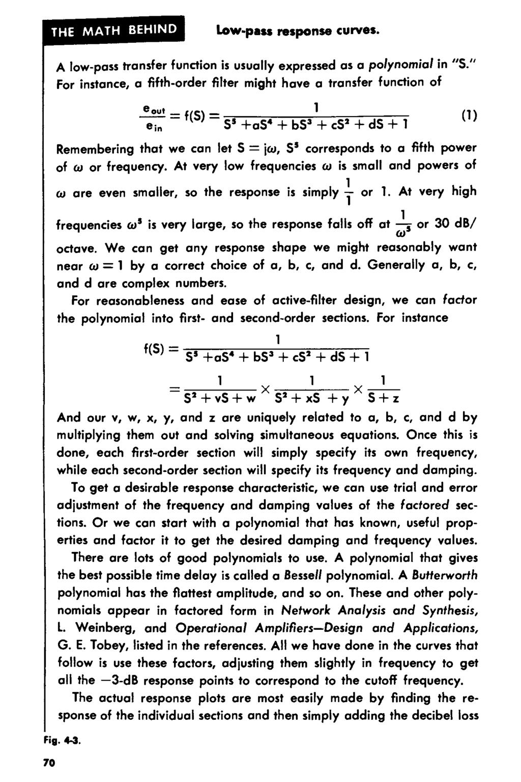
70

71
72
73
74
75

76
77
78
79
80
81
82
83

84

85
86
87
88
89
90
91

92

93
94

95
96
97

98

99
100
101
102
103
104
105

106

107
108

109
110

111
112

113

114
115
116
117

118
119

120
121
122
123
124
125
126
127

128
129
130
131
132
133

134
135
136
137
138
139
140
141
142
143
144
145
146
147
148

149
150
151
152
153
154
155
156
157
158
159
160
161
162

163
164
165
166
167
168
169
170 about the same as the average value of the tuning resistor. Often a blocking capacitor can be provided at the output of an active highpass section to completely eliminate any offset shifts from appearing in the output. SECOND-ORDER HIGH-PASS CIRCUITS We can use the second-order low-pass circuits over again, rearranging them only slightly to get high-pass responses. The four lowpass responses were the unity-gain Sallen-Key, the equal-componentvalue Sallen-Key, the unity-gain state-variable, and the variable-gain state-variable. Unity-Gain Sallen-Key Circuit The math behind both Sallen-Key high-pass circuits appears in Fig As with the low-pass circuits, we have two cascaded RC sections driving an operational amplifier. The op amp both unloads the circuit from any output and feeds back just the right amount of THE MATH BEHIND Sallen-Key, high-pass, second-order sections. Sellen-Key, second-order, high-pass filters can usually be redrawn into a passive network with an active source that looks like this: Cl CZ -11 RI RZ Kta K e ou1 Since this network has to behave identically for any reasonable voltage at any point, it is convenient to force ea = 1 volt and e 0u1 = Kea = K. Solve for i i, i 2, i 3 and then sum them: Fig _ 1 volt_ 1 l3-r2-r2 _ i 3 _ 1 _ jcur2c2 + 1 v - l + l jcuc2 - + jcur2c2 - jcur2c2 K-v i 2 =- Rl ii = (e; n - v)jcucl 171
171
172
173
174
175
176
177 eb p _ eh p e _,P - - SR2C2 - + S 2 RlClR2C2 which rearranges to Ke; n = - eh p + de b p - E!l p _ eh p d eh p (- K)ein - e h p + SRlCl + S 2 RlR , s2 d l + RlCl S + RlR2ClC2 eout -KS 2 If RlCl = R2C2 = l, this becomes eout_ -KS 2 e i n - S 2 + ds + l There are several ways to realize the summing block: (A) Unity gain: (B) Variable gain: as previously analyzed in Fig. 6-9 and Chapter 2. Fig. 8-8-continued. 178
178
179
180
181 Keep the ratio of these three resistors at 1:1:1 at all times. Change j FREQUENCY! smoothly by varying these two resistors. Keep both resistors identical in value at all times. A 10:1 resistance change provides a 10: 1 frequency change with the lower resistance values providing the higher frequencies. Change I FREQUENCY! in steps by switching these capacitors. Keep both capacitors identical in value at all times. Doubling the capacitors halve, frequency and vice versa. e In to---,,,, )/1( LP is adjusted with this resistor. Gain is unity if this resistor equalj the others on the (-) input. Doubling the resistor ha/vu the gain and vice versa. L oe.., 1 HIGH-PASS p H., _,.,,...,::..._,,......_--o Resistor, marked* are not critical and often may be replaced with short circuits. Ideally, the resistance on the + and - in pulj should be equal for minimum offset. I must return to ground via low-impedance de path. GAIN -K Change 1 DAMPING i by changing the ratio of these two resi,tors. Keep the left resistor d times the right one at all times. Absolute value of these resistors is not critical. (Circuit becomes low-pass or band pass by selecting LP or BP output,.) Fig Adjusting or tuning the variabl.-gain, st t- riable, second-order high-pass section. 182
182
183
184
185 If you can use the equal-component-value Sallen-Key circuit: 1. Referring to your original filter problem and using Chapter 4, choose a shape and order that will do the job. 2. Select this circuit from Figs through 8-19 and substitute the proper resistance values. 3. Scale the circuit to your cutoff frequency, using Fig or calculating capacitor ratios inversely as frequency. 101( (A) Typical third-order, two op-amp filter (flattest amplitude, I-kHz cutoff shown). Make this capacitor I TEN TIMES! its former value. \ ;r - / 100 Make this resistor!one TENTH I its former value.!ok _,.. (8) One-op-amp approximation to (A). >-+--o,..., I INPUT IMPEDANCE I of this circuit is I / I 0 that of circuit (A). Fig Appr oximating a third-order high-pass circuit with a single op amp. 4. Tune and adjust the circuit, using the guidelines in this chapter and Chapter 9. For very low frequencies, consider a lox increase in impedance level to get by with smaller capacitors. To build any active high-pass filter: Referring to your original filter problem and using Chapter 4, choose a shape and order that will do the job, along with a list of the frequency and damping values for each section and an accuracy specification. 2. Pick a suitable second-order section from this chapter for each
186
187
188
 State- 250 Hz Variable 50 khz 20 khz 50 khz 5 khz 190 Fig.")
189 I. 05. IB ', 'h.,,. -1, /o -,,. 1', " -1, t..-,;f- r{1t-.,, <" " l0hz 100 Hz, - " I khz " l0khz FREQUEl«:Y Fig Capacitance values for frequency scaling LM318 Unity-Gain 2.5 khz Solien-Key Equal-Component- Value Solien- 1.0 khz Key Unity-Gain 2.5 khz State-Variable Gain-of-Ten (20 db) State- 250 Hz Variable 50 khz 20 khz 50 khz 5 khz 190 Fig Recommended highest cutoff frequency limits for the op amps of Chapter 2. There is a one decade minimum passband with these limits.
190
191
192
193

194
195
196

197
198
199
200
201

202
203
204
205
206
207
208
209
210
211
212

213
214
215

216
217
218

219

220
221

222

223

224
225
226 DIGITAL CLOCK 12:59:02 wwv RECEIVER loo-hz ACTIVE LOW-PASS FILTER IIVELER AND DETECTOR CODE CONVERTER Fig Self-resetting, always-accurate clock. The timing information of the radio station WWV service appears as a 100-Hz subcarrier on the audio. The audio output of a communications receiver ( Fig ) is routed through an active filter that sharply attenuates everything about 100 Hz and mildly attenuates the lower frequencies to eliminate power-supply hum and extra noise. Since extra attenuation of 100-Hz signals can be contrib uted by the output amplifier and particularly by the output trans former, the signal is best obtained directly at the detector or at a low level audio stage. The output of the active filter is stabilized in amplitude and then converted into a series of pulses whose time width establishes one bit at a time of a complete code. The bits arrive at a one-per-second rate. A binary zero lasts 0.2 second; a "l" lasts 0.5 second, and a control or frame pulse lasts 0.8 second. The serial code is then converted to a parallel word with a shift register and then loaded into the timing system for automatic correction. More information on these techniques appears in NBS Special Publication No PSYCHEDELIC LIGHTING Most psychedelic lighting systems relate a visual display of some sort to music. One approach is shown in Fig We take an audio signal from the speaker system, chop it up into spectral chunks with a group of active bandpass filters, and then control a semiconductor controlled rectifier ( SCR) or a triac in proportion to the amplitude of the signals in each channel. The SCR or triac then drives the load, several hundred to a few thousand watts of light. The blue lamps follow the lows, the yellows the accompaniment, the reds the rhythm, and so on, or whatever color combination is selected. The lamps can be projected onto a display or viewed through patterned but transparent plastic materials to create the final display effects. Two-pole bandpass filters one-octave wide ( 2: 1 frequency) with a 1-dB dip in them are a good approach ( see example of Figs
227

228
229
230
231
232
233
234
235
236
237
238
239
240 Don Lancaster's ACTIVE FILTER COOKBOOK An active filter needs no inductors. Instead, opamps, resistors, and capacitors get used for better results. Advantages include lower cost, easy tuning, simple design, and modularity. This Don Lancaster classic is by far the best selling active filter book of all time. It gives you everything you'll need to know to build active lowpass, bandpass, and highpass filters. You'll find both instant design charts and the math behind coverage. Responses from Bessel to Chebychev to Elliptic. Plus circuits from Sallen and Key through State Variable. Chapters include active filter basics; opamps; first and second order networks; lowpass, bandpass, and highpass responses; lowpass, bandpass, and highpass circuits; tuning and voltage control; and real-world ideas and applications. Microcomputer pioneer and guru Don Lancaster is the author of 34 books, 2 videos, and countless articles. He is considered by some to be the father of the personal computer for early work on low cost video terminal displays. Others call him the patron saint of the Walter Mitties of the World. Don has columns in many tech magazines and is the Sysop for the GEnie PSRT RoundTable. He also heads Synergetics, a new age design and consulting firm. Don's avocations include firefighting,spelunking, bicycling, and tinaja questing. Don maintains a no-charge voice helpline at (928) and can be reached at don@tinaja.com or ISBN > ISBN Synergetics Press Box 809 Thatcher AZ 85552
Chapter 19 Operational Amplifiers
 Chapter 19 Operational Amplifiers The operational amplifier, or op-amp, is a basic building block of modern electronics. Op-amps date back to the early days of vacuum tubes, but they only became common
Chapter 12: The Operational Amplifier
 Chapter 12: The Operational Amplifier 12.1: Introduction to Operational Amplifier (Op-Amp) Operational amplifiers (op-amps) are very high gain dc coupled amplifiers with differential inputs; they are used
Frequency Response of Filters
 School of Engineering Department of Electrical and Computer Engineering 332:224 Principles of Electrical Engineering II Laboratory Experiment 2 Frequency Response of Filters 1 Introduction Objectives To
More Filter Design on a Budget
 Application Report SLOA096 December 2001 More Filter Design on a Budget Bruce Carter High Performance Linear Products ABSTRACT This document describes filter design from the standpoint of cost. Filter
Sophomore Physics Laboratory (PH005/105)
") CALIFORNIA INSTITUTE OF TECHNOLOGY PHYSICS MATHEMATICS AND ASTRONOMY DIVISION Sophomore Physics Laboratory (PH5/15) Analog Electronics Active Filters Copyright c Virgínio de Oliveira Sannibale, 23 (Revision
CALIFORNIA INSTITUTE OF TECHNOLOGY PHYSICS MATHEMATICS AND ASTRONOMY DIVISION Sophomore Physics Laboratory (PH5/15) Analog Electronics Active Filters Copyright c Virgínio de Oliveira Sannibale, 23 (Revision
Op Amp Circuit Collection
 Op Amp Circuit Collection Note: National Semiconductor recommends replacing 2N2920 and 2N3728 matched pairs with LM394 in all application circuits. Section 1 Basic Circuits Inverting Amplifier Difference
LM 358 Op Amp. If you have small signals and need a more useful reading we could amplify it using the op amp, this is commonly used in sensors.
 LM 358 Op Amp S k i l l L e v e l : I n t e r m e d i a t e OVERVIEW The LM 358 is a duel single supply operational amplifier. As it is a single supply it eliminates the need for a duel power supply, thus
An Adjustable Audio Filter System for the Receiver - Part 1
 1 of 7 An Adjustable Audio Filter System for the Receiver - Part 1 The audio response is shaped as required using Switched Capacitor Filters Lloyd Butler VK5BR Front panel view of the original receiver
2.161 Signal Processing: Continuous and Discrete Fall 2008
 MT OpenCourseWare http://ocw.mit.edu.6 Signal Processing: Continuous and Discrete Fall 00 For information about citing these materials or our Terms of Use, visit: http://ocw.mit.edu/terms. MASSACHUSETTS
Precision Diode Rectifiers
 by Kenneth A. Kuhn March 21, 2013 Precision half-wave rectifiers An operational amplifier can be used to linearize a non-linear function such as the transfer function of a semiconductor diode. The classic
PIEZO FILTERS INTRODUCTION
 For more than two decades, ceramic filter technology has been instrumental in the proliferation of solid state electronics. A view of the future reveals that even greater expectations will be placed on
OPERATIONAL AMPLIFIERS. o/p
 OPERATIONAL AMPLIFIERS 1. If the input to the circuit of figure is a sine wave the output will be i/p o/p a. A half wave rectified sine wave b. A fullwave rectified sine wave c. A triangular wave d. A
Filter Comparison. Match #1: Analog vs. Digital Filters
 CHAPTER 21 Filter Comparison Decisions, decisions, decisions! With all these filters to choose from, how do you know which to use? This chapter is a head-to-head competition between filters; we'll select
Digital to Analog Converter. Raghu Tumati
 Digital to Analog Converter Raghu Tumati May 11, 2006 Contents 1) Introduction............................... 3 2) DAC types................................... 4 3) DAC Presented.............................
Laboratory #5: RF Filter Design
 EEE 194 RF Laboratory Exercise 5 1 Laboratory #5: RF Filter Design I. OBJECTIVES A. Design a third order low-pass Chebyshev filter with a cutoff frequency of 330 MHz and 3 db ripple with equal terminations
ε: Voltage output of Signal Generator (also called the Source voltage or Applied
 Experiment #10: LR & RC Circuits Frequency Response EQUIPMENT NEEDED Science Workshop Interface Power Amplifier (2) Voltage Sensor graph paper (optional) (3) Patch Cords Decade resistor, capacitor, and
Use and Application of Output Limiting Amplifiers (HFA1115, HFA1130, HFA1135)
") Use and Application of Output Limiting Amplifiers (HFA111, HFA110, HFA11) Application Note November 1996 AN96 Introduction Amplifiers with internal voltage clamps, also known as limiting amplifiers, have
Use and Application of Output Limiting Amplifiers (HFA111, HFA110, HFA11) Application Note November 1996 AN96 Introduction Amplifiers with internal voltage clamps, also known as limiting amplifiers, have
LR Phono Preamps. Pete Millett ETF.13. pmillett@hotmail.com
 LR Phono Preamps Pete Millett ETF.13 pmillett@hotmail.com Agenda A bit about me Part 1: What is, and why use, RIAA? Grooves on records The RIAA standard Implementations of RIAA EQ networks and preamps
isim ACTIVE FILTER DESIGNER NEW, VERY CAPABLE, MULTI-STAGE ACTIVE FILTER DESIGN TOOL
 isim ACTIVE FILTER DESIGNER NEW, VERY CAPABLE, MULTI-STAGE ACTIVE FILTER DESIGN TOOL Michael Steffes Sr. Applications Manager 12/15/2010 SIMPLY SMARTER Introduction to the New Active Filter Designer Scope
Constructing a precision SWR meter and antenna analyzer. Mike Brink HNF, Design Technologist.
 Constructing a precision SWR meter and antenna analyzer. Mike Brink HNF, Design Technologist. Abstract. I have been asked to put together a detailed article on a SWR meter. In this article I will deal
LAB 12: ACTIVE FILTERS
 A. INTRODUCTION LAB 12: ACTIVE FILTERS After last week s encounter with op- amps we will use them to build active filters. B. ABOUT FILTERS An electric filter is a frequency-selecting circuit designed
Operational Amplifier - IC 741
 Operational Amplifier - IC 741 Tabish December 2005 Aim: To study the working of an 741 operational amplifier by conducting the following experiments: (a) Input bias current measurement (b) Input offset
DIGITAL-TO-ANALOGUE AND ANALOGUE-TO-DIGITAL CONVERSION
 DIGITAL-TO-ANALOGUE AND ANALOGUE-TO-DIGITAL CONVERSION Introduction The outputs from sensors and communications receivers are analogue signals that have continuously varying amplitudes. In many systems
6.101 Final Project Report Class G Audio Amplifier
 6.101 Final Project Report Class G Audio Amplifier Mark Spatz 4/3/2014 1 1 Introduction For my final project, I designed and built a 150 Watt audio amplifier to replace the underpowered and unreliable
CTCSS REJECT HIGH PASS FILTERS IN FM RADIO COMMUNICATIONS AN EVALUATION. Virgil Leenerts WØINK 8 June 2008
 CTCSS REJECT HIGH PASS FILTERS IN FM RADIO COMMUNICATIONS AN EVALUATION Virgil Leenerts WØINK 8 June 28 The response of the audio voice band high pass filter is evaluated in conjunction with the rejection
The front end of the receiver performs the frequency translation, channel selection and amplification of the signal.
 Many receivers must be capable of handling a very wide range of signal powers at the input while still producing the correct output. This must be done in the presence of noise and interference which occasionally
Technical Note #3. Error Amplifier Design and Applications. Introduction
 Technical Note #3 Error Amplifier Design and Applications Introduction All regulating power supplies require some sort of closed-loop control to force the output to match the desired value. Both digital
MAS.836 HOW TO BIAS AN OP-AMP
 MAS.836 HOW TO BIAS AN OP-AMP Op-Amp Circuits: Bias, in an electronic circuit, describes the steady state operating characteristics with no signal being applied. In an op-amp circuit, the operating characteristic
Transistor Amplifiers
 Physics 3330 Experiment #7 Fall 1999 Transistor Amplifiers Purpose The aim of this experiment is to develop a bipolar transistor amplifier with a voltage gain of minus 25. The amplifier must accept input
SECTION 5-5: FREQUENCY TRANSFORMATIONS
 ANALOG FILTERS FREQUENCY TRANSFORMATIONS SECTION 55: FREQUENCY TRANSFORMATIONS Until now, only filters using the lowpass configuration have been examined. In this section, transforming the lowpass prototype
TL082 Wide Bandwidth Dual JFET Input Operational Amplifier
 TL082 Wide Bandwidth Dual JFET Input Operational Amplifier General Description These devices are low cost high speed dual JFET input operational amplifiers with an internally trimmed input offset voltage
What you will do. Build a 3-band equalizer. Connect to a music source (mp3 player) Low pass filter High pass filter Band pass filter
 Low pass filter High pass filter Band pass filter") Audio Filters What you will do Build a 3-band equalizer Low pass filter High pass filter Band pass filter Connect to a music source (mp3 player) Adjust the strength of low, high, and middle frequencies
Audio Filters What you will do Build a 3-band equalizer Low pass filter High pass filter Band pass filter Connect to a music source (mp3 player) Adjust the strength of low, high, and middle frequencies
Bipolar Transistor Amplifiers
 Physics 3330 Experiment #7 Fall 2005 Bipolar Transistor Amplifiers Purpose The aim of this experiment is to construct a bipolar transistor amplifier with a voltage gain of minus 25. The amplifier must
Using the Texas Instruments Filter Design Database
 Application Report SLOA062 July, 2001 Bruce Carter Using the Texas Instruments Filter Design Database High Performance Linear Products ABSTRACT Texas Instruments applications personnel have decades of
Lock - in Amplifier and Applications
 Lock - in Amplifier and Applications What is a Lock in Amplifier? In a nut shell, what a lock-in amplifier does is measure the amplitude V o of a sinusoidal voltage, V in (t) = V o cos(ω o t) where ω o
Positive Feedback and Oscillators
 Physics 3330 Experiment #6 Fall 1999 Positive Feedback and Oscillators Purpose In this experiment we will study how spontaneous oscillations may be caused by positive feedback. You will construct an active
A Single-Supply Op-Amp Circuit Collection
 Application Report SLOA058 November 2000 A SingleSupply OpAmp Circuit Collection Bruce Carter OpAmp Applications, High Performance Linear Products One of the biggest problems for designers of opamp circuitry
A Basic Introduction to Filters Active Passive and Switched-Capacitor
 A Basic Introduction to Filters Active Passive and Switched-Capacitor 1 0 INTRODUCTION Filters of some sort are essential to the operation of most electronic circuits It is therefore in the interest of
SINGLE-SUPPLY OPERATION OF OPERATIONAL AMPLIFIERS
 SINGLE-SUPPLY OPERATION OF OPERATIONAL AMPLIFIERS One of the most common applications questions on operational amplifiers concerns operation from a single supply voltage. Can the model OPAxyz be operated
NAPIER University School of Engineering. Electronic Systems Module : SE32102 Analogue Filters Design And Simulation. 4 th order Butterworth response
 NAPIER University School of Engineering Electronic Systems Module : SE32102 Analogue Filters Design And Simulation. 4 th order Butterworth response In R1 R2 C2 C1 + Opamp A - R1 R2 C2 C1 + Opamp B - Out
Agilent AN 1316 Optimizing Spectrum Analyzer Amplitude Accuracy
 Agilent AN 1316 Optimizing Spectrum Analyzer Amplitude Accuracy Application Note RF & Microwave Spectrum Analyzers Table of Contents 3 3 4 4 5 7 8 8 13 13 14 16 16 Introduction Absolute versus relative
Design of op amp sine wave oscillators
 Design of op amp sine wave oscillators By on Mancini Senior Application Specialist, Operational Amplifiers riteria for oscillation The canonical form of a feedback system is shown in Figure, and Equation
Understanding Power Impedance Supply for Optimum Decoupling
 Introduction Noise in power supplies is not only caused by the power supply itself, but also the load s interaction with the power supply (i.e. dynamic loads, switching, etc.). To lower load induced noise,
Analog and Digital Filters Anthony Garvert November 13, 2015
 Analog and Digital Filters Anthony Garvert November 13, 2015 Abstract In circuit analysis and performance, a signal transmits some form of information, such as a voltage or current. However, over a range
5B5BBasic RC Oscillator Circuit
 5B5BBasic RC Oscillator Circuit The RC Oscillator which is also called a Phase Shift Oscillator, produces a sine wave output signal using regenerative feedback from the resistor-capacitor combination.
Kit 106. 50 Watt Audio Amplifier
 Kit 106 50 Watt Audio Amplifier T his kit is based on an amazing IC amplifier module from ST Electronics, the TDA7294 It is intended for use as a high quality audio class AB amplifier in hi-fi applications
A Differential Op-Amp Circuit Collection
 Application Report SLOA0 July 00 Bruce Carter A Differential OpAmp Circuit Collection High Performance Linear Products ABSTRACT All opamps are differential input devices. Designers are accustomed to working
Reading: HH Sections 4.11 4.13, 4.19 4.20 (pgs. 189-212, 222 224)
") 6 OP AMPS II 6 Op Amps II In the previous lab, you explored several applications of op amps. In this exercise, you will look at some of their limitations. You will also examine the op amp integrator and
6 OP AMPS II 6 Op Amps II In the previous lab, you explored several applications of op amps. In this exercise, you will look at some of their limitations. You will also examine the op amp integrator and
Impedance Matching and Matching Networks. Valentin Todorow, December, 2009
 Impedance Matching and Matching Networks Valentin Todorow, December, 2009 RF for Plasma Processing - Definition of RF What is RF? The IEEE Standard Dictionary of Electrical and Electronics Terms defines
Programmable-Gain Transimpedance Amplifiers Maximize Dynamic Range in Spectroscopy Systems
 Programmable-Gain Transimpedance Amplifiers Maximize Dynamic Range in Spectroscopy Systems PHOTODIODE VOLTAGE SHORT-CIRCUIT PHOTODIODE SHORT- CIRCUIT VOLTAGE 0mV DARK ark By Luis Orozco Introduction Precision
TDA2040. 20W Hi-Fi AUDIO POWER AMPLIFIER
 20W Hi-Fi AUDIO POWER AMPLIFIER DESCRIPTION The TDA2040 is a monolithic integrated circuit in Pentawatt package, intended for use as an audio class AB amplifier. Typically it provides 22W output power
Op-Amp Simulation EE/CS 5720/6720. Read Chapter 5 in Johns & Martin before you begin this assignment.
 Op-Amp Simulation EE/CS 5720/6720 Read Chapter 5 in Johns & Martin before you begin this assignment. This assignment will take you through the simulation and basic characterization of a simple operational
LM101A LM201A LM301A Operational Amplifiers
 LM101A LM201A LM301A Operational Amplifiers General Description The LM101A series are general purpose operational amplifiers which feature improved performance over industry standards like the LM709 Advanced
LM118/LM218/LM318 Operational Amplifiers
 LM118/LM218/LM318 Operational Amplifiers General Description The LM118 series are precision high speed operational amplifiers designed for applications requiring wide bandwidth and high slew rate. They
A Differential Op-Amp Circuit Collection
 Application Report SLOA0A April 00 A Differential OpAmp Circuit Collection Bruce Carter High Performance Linear Products ABSTRACT All opamps are differential input devices. Designers are accustomed to
Chapter 16. Active Filter Design Techniques. Excerpted from Op Amps for Everyone. Literature Number SLOA088. Literature Number: SLOD006A
 hapter 16 Active Filter Design Techniques Literature Number SLOA088 Excerpted from Op Amps for Everyone Literature Number: SLOD006A hapter 16 Active Filter Design Techniques Thomas Kugelstadt 16.1 Introduction
Application Notes FREQUENCY LINEAR TUNING VARACTORS FREQUENCY LINEAR TUNING VARACTORS THE DEFINITION OF S (RELATIVE SENSITIVITY)
") FREQUENY LINEAR TUNING VARATORS FREQUENY LINEAR TUNING VARATORS For several decades variable capacitance diodes (varactors) have been used as tuning capacitors in high frequency circuits. Most of these
FREQUENY LINEAR TUNING VARATORS FREQUENY LINEAR TUNING VARATORS For several decades variable capacitance diodes (varactors) have been used as tuning capacitors in high frequency circuits. Most of these
Application Report SLOA024B
 Application Report July 999 Revised September 2002 Mixed Signal Products SLOA024B IMPORTANT NOTICE Texas Instruments Incorporated and its subsidiaries (TI) reserve the right to make corrections, modifications,
Scaling and Biasing Analog Signals
 Scaling and Biasing Analog Signals November 2007 Introduction Scaling and biasing the range and offset of analog signals is a useful skill for working with a variety of electronics. Not only can it interface
THE BASICS OF PLL FREQUENCY SYNTHESIS
 Supplementary Reading for 27 - Oscillators Ron Bertrand VK2DQ http://www.radioelectronicschool.com THE BASICS OF PLL FREQUENCY SYNTHESIS The phase locked loop (PLL) method of frequency synthesis is now
Analog Filters. A common instrumentation filter application is the attenuation of high frequencies to avoid frequency aliasing in the sampled data.
 Analog Filters Filters can be used to attenuate unwanted signals such as interference or noise or to isolate desired signals from unwanted. They use the frequency response of a measuring system to alter
www.jameco.com 1-800-831-4242
 Distributed by: www.jameco.com 1-800-831-4242 The content and copyrights of the attached material are the property of its owner. LF411 Low Offset, Low Drift JFET Input Operational Amplifier General Description
Understanding Power Splitters
 Understanding Power Splitters How they work, what parameters are critical, and how to select the best value for your application. Basically, a 0 splitter is a passive device which accepts an input signal
ARRL Morse Code Oscillator, How It Works By: Mark Spencer, WA8SME
 The national association for AMATEUR RADIO ARRL Morse Code Oscillator, How It Works By: Mark Spencer, WA8SME This supplement is intended for use with the ARRL Morse Code Oscillator kit, sold separately.
Making Accurate Voltage Noise and Current Noise Measurements on Operational Amplifiers Down to 0.1Hz
 Author: Don LaFontaine Making Accurate Voltage Noise and Current Noise Measurements on Operational Amplifiers Down to 0.1Hz Abstract Making accurate voltage and current noise measurements on op amps in
LM833,LMF100,MF10. Application Note 779 A Basic Introduction to Filters - Active, Passive,and. Switched Capacitor. Literature Number: SNOA224A
 LM833,LMF100,MF10 Application Note 779 A Basic Introduction to Filters - Active, Passive,and Switched Capacitor Literature Number: SNOA224A A Basic Introduction to Filters Active, Passive, and Switched-Capacitor
Operational Amplifiers
 Module 6 Amplifiers Operational Amplifiers The Ideal Amplifier What you ll learn in Module 6. Section 6.0. Introduction to Operational Amplifiers. Understand Concept of the Ideal Amplifier and the Need
Section 3. Sensor to ADC Design Example
 Section 3 Sensor to ADC Design Example 3-1 This section describes the design of a sensor to ADC system. The sensor measures temperature, and the measurement is interfaced into an ADC selected by the systems
LM386 Low Voltage Audio Power Amplifier
 Low Voltage Audio Power Amplifier General Description The LM386 is a power amplifier designed for use in low voltage consumer applications. The gain is internally set to 20 to keep external part count
The W5JCK Guide to the Mathematic Equations Required for the Amateur Extra Class Exam
 The W5JCK Guide to the Mathematic Equations Required for the Amateur Extra Class Exam This document contains every question from the Extra Class (Element 4) Question Pool* that requires one or more mathematical
Basic Op Amp Circuits
 Basic Op Amp ircuits Manuel Toledo INEL 5205 Instrumentation August 3, 2008 Introduction The operational amplifier (op amp or OA for short) is perhaps the most important building block for the design of
A Short Discussion on Summing Busses and Summing Amplifiers By Fred Forssell Copyright 2001, by Forssell Technologies All Rights Reserved
 A Short Discussion on Summing Busses and Summing Amplifiers By Fred Forssell Copyright 2001, by Forssell Technologies All Rights Reserved The summing network in mixing consoles is an easily misunderstood
A Low-Cost VCA Limiter
 The circuits within this application note feature THAT218x to provide the essential function of voltage-controlled amplifier (VCA). Since writing this note, THAT has introduced a new dual VCA, as well
FILTERS - IN RADIO COMMUNICATIONS
 Reading 32 Ron Bertrand VK2DQ http://www.radioelectronicschool.com FILTERS - IN RADIO COMMUNICATIONS RADIO SIGNALS In radio communications we talk a lot about radio signals. A radio signal is a very broad
AM TRANSMITTERS & RECEIVERS
 Reading 30 Ron Bertrand VK2DQ http://www.radioelectronicschool.com AM TRANSMITTERS & RECEIVERS Revision: our definition of amplitude modulation. Amplitude modulation is when the modulating audio is combined
AN-837 APPLICATION NOTE
 APPLICATION NOTE One Technology Way P.O. Box 916 Norwood, MA 262-916, U.S.A. Tel: 781.329.47 Fax: 781.461.3113 www.analog.com DDS-Based Clock Jitter Performance vs. DAC Reconstruction Filter Performance
Nano Stepping Notch Filter Jim Hagerman 02 01 12
 Nano Stepping Notch Filter Jim Hagerman 02 01 12 INTRODUCTION I worked out equations for the von Newman style high power notch filter. This design is tunable over a fairly wide range, but less than an
Analog Signal Conditioning
 Analog Signal Conditioning Analog and Digital Electronics Electronics Digital Electronics Analog Electronics 2 Analog Electronics Analog Electronics Operational Amplifiers Transistors TRIAC 741 LF351 TL084
Chapter 6: From Digital-to-Analog and Back Again
 Chapter 6: From Digital-to-Analog and Back Again Overview Often the information you want to capture in an experiment originates in the laboratory as an analog voltage or a current. Sometimes you want to
TDA2040. 20W Hi-Fi AUDIO POWER AMPLIFIER
 20W Hi-Fi AUDIO POWER AMPLIFIER DESCRIPTION The TDA2040 is a monolithic integrated circuit in Pentawatt package, intended for use as an audio class AB amplifier. Typically it provides 22W output power
Loop Bandwidth and Clock Data Recovery (CDR) in Oscilloscope Measurements. Application Note 1304-6
 in Oscilloscope Measurements. Application Note 1304-6") Loop Bandwidth and Clock Data Recovery (CDR) in Oscilloscope Measurements Application Note 1304-6 Abstract Time domain measurements are only as accurate as the trigger signal used to acquire them. Often
Loop Bandwidth and Clock Data Recovery (CDR) in Oscilloscope Measurements Application Note 1304-6 Abstract Time domain measurements are only as accurate as the trigger signal used to acquire them. Often
Transistor Characteristics and Single Transistor Amplifier Sept. 8, 1997
 Physics 623 Transistor Characteristics and Single Transistor Amplifier Sept. 8, 1997 1 Purpose To measure and understand the common emitter transistor characteristic curves. To use the base current gain
SUMMARY. Additional Digital/Software filters are included in Chart and filter the data after it has been sampled and recorded by the PowerLab.
 This technique note was compiled by ADInstruments Pty Ltd. It includes figures and tables from S.S. Young (2001): Computerized data acquisition and analysis for the life sciences. For further information
AN1991. Audio decibel level detector with meter driver
 Rev. 2.1 20 March 2015 Application note Document information Info Keywords Abstract Content SA604A, LM358, RSSI, cellular radio The SA604A can provide a logarithmic response proportional to the input signal
Prepared by: Paul Lee ON Semiconductor http://onsemi.com
 Introduction to Analog Video Prepared by: Paul Lee ON Semiconductor APPLICATION NOTE Introduction Eventually all video signals being broadcasted or transmitted will be digital, but until then analog video
APPLICATION NOTES POWER DIVIDERS. Things to consider
 Internet Copy Rev A Overview Various RF applications require power to be distributed among various paths. The simplest way this can be done is by using a power splitter/divider. Power dividers are reciprocal
Analog signals are those which are naturally occurring. Any analog signal can be converted to a digital signal.
 3.3 Analog to Digital Conversion (ADC) Analog signals are those which are naturally occurring. Any analog signal can be converted to a digital signal. 1 3.3 Analog to Digital Conversion (ADC) WCB/McGraw-Hill
LAB 7 MOSFET CHARACTERISTICS AND APPLICATIONS
 LAB 7 MOSFET CHARACTERISTICS AND APPLICATIONS Objective In this experiment you will study the i-v characteristics of an MOS transistor. You will use the MOSFET as a variable resistor and as a switch. BACKGROUND
BASIC ELECTRONICS AC CIRCUIT ANALYSIS. December 2011
 AM 5-202 BASIC ELECTRONICS AC CIRCUIT ANALYSIS December 2011 DISTRIBUTION RESTRICTION: Approved for Pubic Release. Distribution is unlimited. DEPARTMENT OF THE ARMY MILITARY AUXILIARY RADIO SYSTEM FORT
Germanium Diode AM Radio
 Germanium Diode AM Radio LAB 3 3.1 Introduction In this laboratory exercise you will build a germanium diode based AM (Medium Wave) radio. Earliest radios used simple diode detector circuits. The diodes
Line Reactors and AC Drives
 Line Reactors and AC Drives Rockwell Automation Mequon Wisconsin Quite often, line and load reactors are installed on AC drives without a solid understanding of why or what the positive and negative consequences
Modification Details.
 Front end receiver modification for DRM: AKD Target Communications receiver. Model HF3. Summary. The receiver was modified and capable of receiving DRM, but performance was limited by the phase noise from
Signal Conditioning Piezoelectric Sensors
 Application Report SLOA033A - September 2000 Signal Conditioning Piezoelectric Sensors James Karki Mixed Signal Products ABSTRACT Piezoelectric elements are used to construct transducers for a vast number
The Phase Modulator In NBFM Voice Communication Systems
 The Phase Modulator In NBFM Voice Communication Systems Virgil Leenerts 8 March 5 The phase modulator has been a point of discussion as to why it is used and not a frequency modulator in what are called
Voltage. Oscillator. Voltage. Oscillator
 fpa 147 Week 6 Synthesis Basics In the early 1960s, inventors & entrepreneurs (Robert Moog, Don Buchla, Harold Bode, etc.) began assembling various modules into a single chassis, coupled with a user interface
Current vs. Voltage Feedback Amplifiers
 Current vs. ltage Feedback Amplifiers One question continuously troubles the analog design engineer: Which amplifier topology is better for my application, current feedback or voltage feedback? In most
Since any real component also has loss due to the resistive component, the average power dissipated is 2 2R
 Quality factor, Q Reactive components such as capacitors and inductors are often described with a figure of merit called Q. While it can be defined in many ways, it s most fundamental description is: Q
LM1036 Dual DC Operated Tone/Volume/Balance Circuit
 LM1036 Dual DC Operated Tone/Volume/Balance Circuit General Description The LM1036 is a DC controlled tone (bass/treble), volume and balance circuit for stereo applications in car radio, TV and audio systems.
LF412 Low Offset Low Drift Dual JFET Input Operational Amplifier
 LF412 Low Offset Low Drift Dual JFET Input Operational Amplifier General Description These devices are low cost high speed JFET input operational amplifiers with very low input offset voltage and guaranteed