Analog signals are those which are naturally occurring. Any analog signal can be converted to a digital signal.
|
|
|
- Jason James Ford
- 7 years ago
- Views:
Transcription
1 3.3 Analog to Digital Conversion (ADC) Analog signals are those which are naturally occurring. Any analog signal can be converted to a digital signal. 1

2 3.3 Analog to Digital Conversion (ADC) WCB/McGraw-Hill The McGraw-Hill Companies, Inc.,

3 3.3 Analog to Digital Conversion (ADC) Quantization: The process by which measurements of analog signals are rounded to discrete values. These discrete values are referred to as bits. Typically, each bit has only two possible states, 0 or 1. This is called the binary system. The number of bits available to describe these values determines the resolution or accuracy. 3

4 3.3 Analog to Digital Conversion (ADC) If you have 3-bit analog to digital converters, the varying analog signal must be quantized to 1 of 8 discrete values. For example, with 2 states and 3 bit conversion there are 2 3 = 8 possible discrete values. 4

5 3.3 Analog to Digital Conversion (ADC) So for a 3-bit analog to digital conversion for an analog signal with an arbitrary maximum amplitude of 10: 5

6 3.3 Analog to Digital Conversion (ADC) Resolution: Defined in terms of number of bits 2 b where b: number of bits e.g. 3 bit resolution yields 8 levels of resolution 8 bit resolution yields 256 levels 16 bit resolution yields levels 6

7 3.3 Analog to Digital Conversion (ADC) 7

8 3.2 Analog Sampling Basics Quantization Quantization is defined as the process of converting an analog signal to a digital representation. Quantization is performed by an analog-to-digital converter (A/D converter or ADC) 8

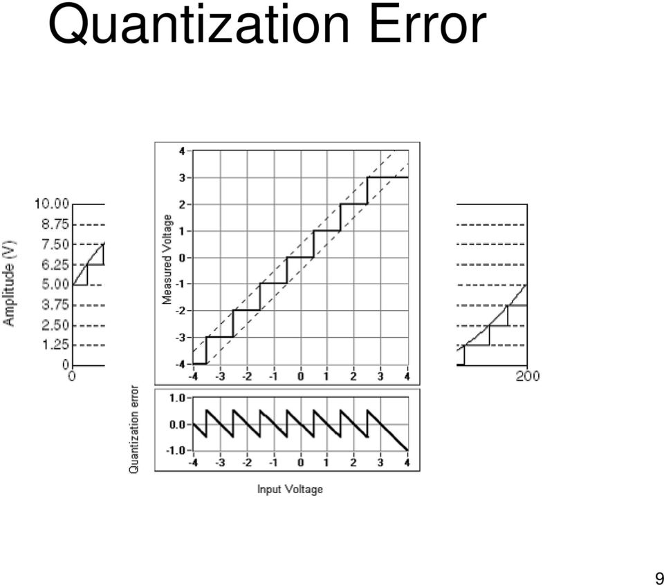
9 Quantization Error 9
10 Dithering Dithering involves the deliberate addition of noise to our input signal. It helps by smearing out the little differences in amplitude resolution 10

11 3.3 Digital to Analog Conversion (DAC) Digital signals are those made by humans (or other sentients) Any digital signal can be converted to an analog signal. 11

12 3.3 Digital to Analog Conversion (DAC) Digital to Analog Conversion WCB/McGraw-Hill The McGraw-Hill Companies, Inc.,

13 Digital to Analog Conversion Digital Data DAC Analog signal

14 3.3 Digital to Analog Conversion (DAC) A DAC Example: MODEM MODEM: modulator/demodulator digital to analog or analog to digital 14

15 3.3 Digital to Analog Conversion (DAC) 3-bit voltage scaling Digital to Analog Converter (DAC) A reference signal, Ref, (eg. voltage) is required. The number of bits, n, fixes the resolution, R, of the DAC. The resolution sets the difference between signal levels. So: R = Ref/2 n. 15

16 3.3 Digital to Analog Conversion (DAC) 3-bit voltage scaling DAC: For a 3-bit DAC, n = 3. Let the reference signal be Ref = 10 VDC. Then: R = Ref/2 n = 10/8 = 1.25VDC. 16

17 3.3 Digital to Analog Conversion (DAC) 17

18 3.3 Digital to Analog Conversion (DAC) 18

19 3.4 Filters Filters are devices which alter the frequency characteristics of an electronic signal. Filters may be designed to be either passive or active. Filters are designed from capacitors, inductors and resistors. There are several common types of filters such as: low-pass, high-pass, band-pass and notch. 1

20 3.4 Filters BLOCK DIAGRAM Input Signal, T( ) in FILTER Output Signal, T( ) out 2

21 3.4 Filters Remember Impedance: Electrical components have responses that vary with frequency. This frequency response is known as impedance, Z. Impedance has both a real and a complex part and is of the form: Z = R + jx where X is called Reactance. So the following relationships hold: Resistor: Z = R + 0*j = R Capacitor: Z = 0 j/ C = 1j/ C Inductor: Z = 0 + L = L Where = omega = 2* Pi * frequency in Hz
22 3.4 Filters Low Pass Filter (LPF) Circuits 4
23 3.4 Filters Low Pass Filter (LPF) Response Filter response, T(w) out for either the RC circuit or the RL circuit is: T(w) out = 1/(1+j / c ) Where the c = cutoff frequency is: c = 1/RC for the RC circuit and c = R/L for the RL circuit 5
24 3.4 Filters Low Pass Filter (LPF) Response 6
25 3.4 Filters Low Pass Filter (LPF) Uses Typical use in bioinstrumentation; remove RF interference from an EKG signal. Source of RF: unshielded leads or long connecting wires/cables. Typical cutoff frequency is 150 Hz 7
26 Low Pass RC Filters p1 8
27 Slide 8 p1 Changes. pcourtoi, 12/20/2004
28 3.4 Filters High Pass Filter (HPF) Circuits 9
29 3.4 Filters High Pass Filter (HPF) Response Filter response, T(w) out for either the RC circuit or the RL circuit is: T(w) out = 1/(1-j c / ) Where c = cutoff frequency is: c = 1/RC for the RC circuit and c = R/L for the RL circuit 10
30 3.4 Filters High Pass Filter (LPF) Response 11
31 3.4 Filters High Pass Filter (HPF) Uses Typical use in bioinstrumentation: remove dc offset and other low frequency interference from an EKG signal. Typical cutoff frequency:.5 Hz 12
32 High Pass RC Filters p2 0V DC Offset 0V 13
33 Slide 13 p2 I changed the image here. pcourtoi, 12/20/2004
34 3.4 Filters Bandpass Filter (BPF) Response 14
35 3.4 Filters Notch (Bandstop) Filter (NPF) Response 15
Laboratory #5: RF Filter Design
 EEE 194 RF Laboratory Exercise 5 1 Laboratory #5: RF Filter Design I. OBJECTIVES A. Design a third order low-pass Chebyshev filter with a cutoff frequency of 330 MHz and 3 db ripple with equal terminations
LAB 12: ACTIVE FILTERS
 A. INTRODUCTION LAB 12: ACTIVE FILTERS After last week s encounter with op- amps we will use them to build active filters. B. ABOUT FILTERS An electric filter is a frequency-selecting circuit designed
Analog Filters. A common instrumentation filter application is the attenuation of high frequencies to avoid frequency aliasing in the sampled data.
 Analog Filters Filters can be used to attenuate unwanted signals such as interference or noise or to isolate desired signals from unwanted. They use the frequency response of a measuring system to alter
ε: Voltage output of Signal Generator (also called the Source voltage or Applied
 Experiment #10: LR & RC Circuits Frequency Response EQUIPMENT NEEDED Science Workshop Interface Power Amplifier (2) Voltage Sensor graph paper (optional) (3) Patch Cords Decade resistor, capacitor, and
Analog Representations of Sound
 Analog Representations of Sound Magnified phonograph grooves, viewed from above: The shape of the grooves encodes the continuously varying audio signal. Analog to Digital Recording Chain ADC Microphone
6.025J Medical Device Design Lecture 3: Analog-to-Digital Conversion Prof. Joel L. Dawson
 Let s go back briefly to lecture 1, and look at where ADC s and DAC s fit into our overall picture. I m going in a little extra detail now since this is our eighth lecture on electronics and we are more
Frequency response: Resonance, Bandwidth, Q factor
 Frequency response: esonance, Bandwidth, Q factor esonance. Let s continue the exploration of the frequency response of circuits by investigating the series circuit shown on Figure. C + V - Figure The
Chapter 10. RC Circuits ISU EE. C.Y. Lee
 Chapter 10 RC Circuits Objectives Describe the relationship between current and voltage in an RC circuit Determine impedance and phase angle in a series RC circuit Analyze a series RC circuit Determine
Analog and Digital Filters Anthony Garvert November 13, 2015
 Analog and Digital Filters Anthony Garvert November 13, 2015 Abstract In circuit analysis and performance, a signal transmits some form of information, such as a voltage or current. However, over a range
DIGITAL-TO-ANALOGUE AND ANALOGUE-TO-DIGITAL CONVERSION
 DIGITAL-TO-ANALOGUE AND ANALOGUE-TO-DIGITAL CONVERSION Introduction The outputs from sensors and communications receivers are analogue signals that have continuously varying amplitudes. In many systems
Sophomore Physics Laboratory (PH005/105)
") CALIFORNIA INSTITUTE OF TECHNOLOGY PHYSICS MATHEMATICS AND ASTRONOMY DIVISION Sophomore Physics Laboratory (PH5/15) Analog Electronics Active Filters Copyright c Virgínio de Oliveira Sannibale, 23 (Revision
CALIFORNIA INSTITUTE OF TECHNOLOGY PHYSICS MATHEMATICS AND ASTRONOMY DIVISION Sophomore Physics Laboratory (PH5/15) Analog Electronics Active Filters Copyright c Virgínio de Oliveira Sannibale, 23 (Revision
b 1 is the most significant bit (MSB) The MSB is the bit that has the most (largest) influence on the analog output
 The MSB is the bit that has the most (largest) influence on the analog output") CMOS Analog IC Design - Chapter 10 Page 10.0-5 BLOCK DIAGRAM OF A DIGITAL-ANALOG CONVERTER b 1 is the most significant bit (MSB) The MSB is the bit that has the most (largest) influence on the analog output
CMOS Analog IC Design - Chapter 10 Page 10.0-5 BLOCK DIAGRAM OF A DIGITAL-ANALOG CONVERTER b 1 is the most significant bit (MSB) The MSB is the bit that has the most (largest) influence on the analog output
Analog Signal Conditioning
 Analog Signal Conditioning Analog and Digital Electronics Electronics Digital Electronics Analog Electronics 2 Analog Electronics Analog Electronics Operational Amplifiers Transistors TRIAC 741 LF351 TL084
Conversion Between Analog and Digital Signals
 ELET 3156 DL - Laboratory #6 Conversion Between Analog and Digital Signals There is no pre-lab work required for this experiment. However, be sure to read through the assignment completely prior to starting
Digital to Analog Converter. Raghu Tumati
 Digital to Analog Converter Raghu Tumati May 11, 2006 Contents 1) Introduction............................... 3 2) DAC types................................... 4 3) DAC Presented.............................
Application Report. 1 Introduction. 2 Resolution of an A-D Converter. 2.1 Signal-to-Noise Ratio (SNR) Harman Grewal... ABSTRACT
 Harman Grewal... ABSTRACT") Application Report SLAA323 JULY 2006 Oversampling the ADC12 for Higher Resolution Harman Grewal... ABSTRACT This application report describes the theory of oversampling to achieve resolutions greater than
Application Report SLAA323 JULY 2006 Oversampling the ADC12 for Higher Resolution Harman Grewal... ABSTRACT This application report describes the theory of oversampling to achieve resolutions greater than
MAS.836 HOW TO BIAS AN OP-AMP
 MAS.836 HOW TO BIAS AN OP-AMP Op-Amp Circuits: Bias, in an electronic circuit, describes the steady state operating characteristics with no signal being applied. In an op-amp circuit, the operating characteristic
FILTERS - IN RADIO COMMUNICATIONS
 Reading 32 Ron Bertrand VK2DQ http://www.radioelectronicschool.com FILTERS - IN RADIO COMMUNICATIONS RADIO SIGNALS In radio communications we talk a lot about radio signals. A radio signal is a very broad
2.161 Signal Processing: Continuous and Discrete Fall 2008
 MT OpenCourseWare http://ocw.mit.edu.6 Signal Processing: Continuous and Discrete Fall 00 For information about citing these materials or our Terms of Use, visit: http://ocw.mit.edu/terms. MASSACHUSETTS
Pressure Transducer to ADC Application
 Application Report SLOA05 October 2000 Pressure Transducer to ADC Application John Bishop ABSTRACT Advanced Analog Products/OpAmp Applications A range of bridgetype transducers can measure numerous process
Designing Gain and Offset in Thirty Seconds
 Application Report SLOA097 February 2002 Designing Gain and Offset in Thirty Seconds Bruce Carter High Performance Linear ABSTRACT This document discusses how to design an operational amplifier (op amp)
Lecture 9. Poles, Zeros & Filters (Lathi 4.10) Effects of Poles & Zeros on Frequency Response (1) Effects of Poles & Zeros on Frequency Response (3)
 Effects of Poles & Zeros on Frequency Response (1) Effects of Poles & Zeros on Frequency Response (3)") Effects of Poles & Zeros on Frequency Response (1) Consider a general system transfer function: zeros at z1, z2,..., zn Lecture 9 Poles, Zeros & Filters (Lathi 4.10) The value of the transfer function
Effects of Poles & Zeros on Frequency Response (1) Consider a general system transfer function: zeros at z1, z2,..., zn Lecture 9 Poles, Zeros & Filters (Lathi 4.10) The value of the transfer function
Basic Op Amp Circuits
 Basic Op Amp ircuits Manuel Toledo INEL 5205 Instrumentation August 3, 2008 Introduction The operational amplifier (op amp or OA for short) is perhaps the most important building block for the design of
Loop Bandwidth and Clock Data Recovery (CDR) in Oscilloscope Measurements. Application Note 1304-6
 in Oscilloscope Measurements. Application Note 1304-6") Loop Bandwidth and Clock Data Recovery (CDR) in Oscilloscope Measurements Application Note 1304-6 Abstract Time domain measurements are only as accurate as the trigger signal used to acquire them. Often
Loop Bandwidth and Clock Data Recovery (CDR) in Oscilloscope Measurements Application Note 1304-6 Abstract Time domain measurements are only as accurate as the trigger signal used to acquire them. Often
1. Oscilloscope is basically a graph-displaying device-it draws a graph of an electrical signal.
 CHAPTER 3: OSCILLOSCOPE AND SIGNAL GENERATOR 3.1 Introduction to oscilloscope 1. Oscilloscope is basically a graph-displaying device-it draws a graph of an electrical signal. 2. The graph show signal change
Frequency Response of Filters
 School of Engineering Department of Electrical and Computer Engineering 332:224 Principles of Electrical Engineering II Laboratory Experiment 2 Frequency Response of Filters 1 Introduction Objectives To
CHAPTER 6 Frequency Response, Bode Plots, and Resonance
 ELECTRICAL CHAPTER 6 Frequency Response, Bode Plots, and Resonance 1. State the fundamental concepts of Fourier analysis. 2. Determine the output of a filter for a given input consisting of sinusoidal
Digital to Analog and Analog to Digital Conversion
 Real world (lab) is Computer (binary) is digital Digital to Analog and Analog to Digital Conversion V t V t D/A or DAC and A/D or ADC D/A Conversion Computer DAC A/D Conversion Computer DAC Digital to
CIRCUITS LABORATORY EXPERIMENT 3. AC Circuit Analysis
 CIRCUITS LABORATORY EXPERIMENT 3 AC Circuit Analysis 3.1 Introduction The steady-state behavior of circuits energized by sinusoidal sources is an important area of study for several reasons. First, the
Inductors in AC Circuits
 Inductors in AC Circuits Name Section Resistors, inductors, and capacitors all have the effect of modifying the size of the current in an AC circuit and the time at which the current reaches its maximum
QUICK START GUIDE FOR DEMONSTRATION CIRCUIT 956 24-BIT DIFFERENTIAL ADC WITH I2C LTC2485 DESCRIPTION
 LTC2485 DESCRIPTION Demonstration circuit 956 features the LTC2485, a 24-Bit high performance Σ analog-to-digital converter (ADC). The LTC2485 features 2ppm linearity, 0.5µV offset, and 600nV RMS noise.
Chapter 6: From Digital-to-Analog and Back Again
 Chapter 6: From Digital-to-Analog and Back Again Overview Often the information you want to capture in an experiment originates in the laboratory as an analog voltage or a current. Sometimes you want to
FAST Fourier Transform (FFT) and Digital Filtering Using LabVIEW
 and Digital Filtering Using LabVIEW") FAST Fourier Transform (FFT) and Digital Filtering Using LabVIEW Wei Lin Department of Biomedical Engineering Stony Brook University Instructor s Portion Summary This experiment requires the student to
FAST Fourier Transform (FFT) and Digital Filtering Using LabVIEW Wei Lin Department of Biomedical Engineering Stony Brook University Instructor s Portion Summary This experiment requires the student to
Properties of electrical signals
 DC Voltage Component (Average voltage) Properties of electrical signals v(t) = V DC + v ac (t) V DC is the voltage value displayed on a DC voltmeter Triangular waveform DC component Half-wave rectifier
SUMMARY. Additional Digital/Software filters are included in Chart and filter the data after it has been sampled and recorded by the PowerLab.
 This technique note was compiled by ADInstruments Pty Ltd. It includes figures and tables from S.S. Young (2001): Computerized data acquisition and analysis for the life sciences. For further information
AP2428.01. A/D Converter. Analog Aspects. C500 and C166 Microcontroller Families. Microcontrollers. Application Note, V 1.
 Application Note, V 1.0, May 2001 AP2428.01 A/D Converter C500 and C166 Microcontroller Families Analog Aspects Microcontrollers Never stop thinking. A/D Converter Revision History: 2001-05 V1.0 Previous
Introduction to Digital Audio
 Introduction to Digital Audio Before the development of high-speed, low-cost digital computers and analog-to-digital conversion circuits, all recording and manipulation of sound was done using analog techniques.
RLC Resonant Circuits
 C esonant Circuits Andrew McHutchon April 20, 203 Capacitors and Inductors There is a lot of inconsistency when it comes to dealing with reactances of complex components. The format followed in this document
1995 Mixed-Signal Products SLAA013
 Application Report 995 Mixed-Signal Products SLAA03 IMPORTANT NOTICE Texas Instruments and its subsidiaries (TI) reserve the right to make changes to their products or to discontinue any product or service
GENERAL POWER SYSTEM WIRING PRACTICES APPLIED TO TECNADYNE DC BRUSHLESS MOTORS
 1/5/2006 Page 1 of 6 GENERAL POWER SYSTEM WIRING PRACTICES APPLIED TO TECNADYNE DC BRUSHLESS MOTORS 1. Introduction The purpose of this application note is to describe some common connection and filtering
DEVELOPMENT OF DEVICES AND METHODS FOR PHASE AND AC LINEARITY MEASUREMENTS IN DIGITIZERS
 DEVELOPMENT OF DEVICES AND METHODS FOR PHASE AND AC LINEARITY MEASUREMENTS IN DIGITIZERS U. Pogliano, B. Trinchera, G.C. Bosco and D. Serazio INRIM Istituto Nazionale di Ricerca Metrologica Torino (Italia)
chapter Introduction to Digital Signal Processing and Digital Filtering 1.1 Introduction 1.2 Historical Perspective
 Introduction to Digital Signal Processing and Digital Filtering chapter 1 Introduction to Digital Signal Processing and Digital Filtering 1.1 Introduction Digital signal processing (DSP) refers to anything
Dithering in Analog-to-digital Conversion
 Application Note 1. Introduction 2. What is Dither High-speed ADCs today offer higher dynamic performances and every effort is made to push these state-of-the art performances through design improvements
NAPIER University School of Engineering. Electronic Systems Module : SE32102 Analogue Filters Design And Simulation. 4 th order Butterworth response
 NAPIER University School of Engineering Electronic Systems Module : SE32102 Analogue Filters Design And Simulation. 4 th order Butterworth response In R1 R2 C2 C1 + Opamp A - R1 R2 C2 C1 + Opamp B - Out
Apprentice Telecommunications Technician Test (CTT) Study Guide
 Study Guide") Apprentice Telecommunications Technician Test (CTT) Study Guide 1 05/2014 Study Guide for Pacific Gas & Electric Company Apprentice Telecommunications Technician Qualifying Test (CTT) About the Test The
Apprentice Telecommunications Technician Test (CTT) Study Guide 1 05/2014 Study Guide for Pacific Gas & Electric Company Apprentice Telecommunications Technician Qualifying Test (CTT) About the Test The
SECTION 5-5: FREQUENCY TRANSFORMATIONS
 ANALOG FILTERS FREQUENCY TRANSFORMATIONS SECTION 55: FREQUENCY TRANSFORMATIONS Until now, only filters using the lowpass configuration have been examined. In this section, transforming the lowpass prototype
CTCSS REJECT HIGH PASS FILTERS IN FM RADIO COMMUNICATIONS AN EVALUATION. Virgil Leenerts WØINK 8 June 2008
 CTCSS REJECT HIGH PASS FILTERS IN FM RADIO COMMUNICATIONS AN EVALUATION Virgil Leenerts WØINK 8 June 28 The response of the audio voice band high pass filter is evaluated in conjunction with the rejection
by Anurag Pulincherry A THESIS submitted to Oregon State University in partial fulfillment of the requirements for the degree of Master of Science
 A Continuous Time Frequency Translating Delta Sigma Modulator by Anurag Pulincherry A THESIS submitted to Oregon State University in partial fulfillment of the requirements for the degree of Master of
Massachusetts Institute of Technology Department of Electrical Engineering and Computer Science. 6.002 Electronic Circuits Spring 2007
 Massachusetts Institute of Technology Department of Electrical Engineering and Computer Science 6.002 Electronic Circuits Spring 2007 Lab 4: Audio Playback System Introduction In this lab, you will construct,
LEVERAGING FPGA AND CPLD DIGITAL LOGIC TO IMPLEMENT ANALOG TO DIGITAL CONVERTERS
 LEVERAGING FPGA AND CPLD DIGITAL LOGIC TO IMPLEMENT ANALOG TO DIGITAL CONVERTERS March 2010 Lattice Semiconductor 5555 Northeast Moore Ct. Hillsboro, Oregon 97124 USA Telephone: (503) 268-8000 www.latticesemi.com
Experiment #11: LRC Circuit (Power Amplifier, Voltage Sensor)
") Experiment #11: LRC Circuit (Power Amplifier, Voltage Sensor) Concept: circuits Time: 30 m SW Interface: 750 Windows file: RLC.SWS EQUIPMENT NEEDED Science Workshop Interface Power Amplifier (2) Voltage
Experiment #11: LRC Circuit (Power Amplifier, Voltage Sensor) Concept: circuits Time: 30 m SW Interface: 750 Windows file: RLC.SWS EQUIPMENT NEEDED Science Workshop Interface Power Amplifier (2) Voltage
Impedance Matching and Matching Networks. Valentin Todorow, December, 2009
 Impedance Matching and Matching Networks Valentin Todorow, December, 2009 RF for Plasma Processing - Definition of RF What is RF? The IEEE Standard Dictionary of Electrical and Electronics Terms defines
AN-837 APPLICATION NOTE
 APPLICATION NOTE One Technology Way P.O. Box 916 Norwood, MA 262-916, U.S.A. Tel: 781.329.47 Fax: 781.461.3113 www.analog.com DDS-Based Clock Jitter Performance vs. DAC Reconstruction Filter Performance
MATRIX TECHNICAL NOTES
 200 WOOD AVENUE, MIDDLESEX, NJ 08846 PHONE (732) 469-9510 FAX (732) 469-0418 MATRIX TECHNICAL NOTES MTN-107 TEST SETUP FOR THE MEASUREMENT OF X-MOD, CTB, AND CSO USING A MEAN SQUARE CIRCUIT AS A DETECTOR
Pulse Width Modulation (PWM) LED Dimmer Circuit. Using a 555 Timer Chip
 LED Dimmer Circuit. Using a 555 Timer Chip") Pulse Width Modulation (PWM) LED Dimmer Circuit Using a 555 Timer Chip Goals of Experiment Demonstrate the operation of a simple PWM circuit that can be used to adjust the intensity of a green LED by varying
Pulse Width Modulation (PWM) LED Dimmer Circuit Using a 555 Timer Chip Goals of Experiment Demonstrate the operation of a simple PWM circuit that can be used to adjust the intensity of a green LED by varying
Lock - in Amplifier and Applications
 Lock - in Amplifier and Applications What is a Lock in Amplifier? In a nut shell, what a lock-in amplifier does is measure the amplitude V o of a sinusoidal voltage, V in (t) = V o cos(ω o t) where ω o
VCO Phase noise. Characterizing Phase Noise
 VCO Phase noise Characterizing Phase Noise The term phase noise is widely used for describing short term random frequency fluctuations of a signal. Frequency stability is a measure of the degree to which
TDA2040. 20W Hi-Fi AUDIO POWER AMPLIFIER
 20W Hi-Fi AUDIO POWER AMPLIFIER DESCRIPTION The TDA2040 is a monolithic integrated circuit in Pentawatt package, intended for use as an audio class AB amplifier. Typically it provides 22W output power
The front end of the receiver performs the frequency translation, channel selection and amplification of the signal.
 Many receivers must be capable of handling a very wide range of signal powers at the input while still producing the correct output. This must be done in the presence of noise and interference which occasionally
DAC Digital To Analog Converter
 DAC Digital To Analog Converter DAC Digital To Analog Converter Highlights XMC4000 provides two digital to analog converters. Each can output one analog value. Additional multiple analog waves can be generated
What you will do. Build a 3-band equalizer. Connect to a music source (mp3 player) Low pass filter High pass filter Band pass filter
 Low pass filter High pass filter Band pass filter") Audio Filters What you will do Build a 3-band equalizer Low pass filter High pass filter Band pass filter Connect to a music source (mp3 player) Adjust the strength of low, high, and middle frequencies
Audio Filters What you will do Build a 3-band equalizer Low pass filter High pass filter Band pass filter Connect to a music source (mp3 player) Adjust the strength of low, high, and middle frequencies
LR Phono Preamps. Pete Millett ETF.13. pmillett@hotmail.com
 LR Phono Preamps Pete Millett ETF.13 pmillett@hotmail.com Agenda A bit about me Part 1: What is, and why use, RIAA? Grooves on records The RIAA standard Implementations of RIAA EQ networks and preamps
Digital To Analog Converter with Sine Wave Output
 Digital To Analog Converter with Sine Wave Output Overview In this Lab we will build a resistive ladder network and use the BASIC Stamp to generate the digital data for the D/A conversions. PBASIC will
Android based Alcohol detection system using Bluetooth technology
 For more Project details visit: http://www.projectsof8051.com/android-based-alcohol-detection-system-usingbluetooth-technology/ Code 1435 Project Title Android based Alcohol detection system using Bluetooth
Impedance 50 (75 connectors via adapters)
") VECTOR NETWORK ANALYZER PLANAR TR1300/1 DATA SHEET Frequency range: 300 khz to 1.3 GHz Measured parameters: S11, S21 Dynamic range of transmission measurement magnitude: 130 db Measurement time per point:
VECTOR NETWORK ANALYZER PLANAR TR1300/1 DATA SHEET Frequency range: 300 khz to 1.3 GHz Measured parameters: S11, S21 Dynamic range of transmission measurement magnitude: 130 db Measurement time per point:
An Adjustable Audio Filter System for the Receiver - Part 1
 1 of 7 An Adjustable Audio Filter System for the Receiver - Part 1 The audio response is shaped as required using Switched Capacitor Filters Lloyd Butler VK5BR Front panel view of the original receiver
HP 8970B Option 020. Service Manual Supplement
 HP 8970B Option 020 Service Manual Supplement Service Manual Supplement HP 8970B Option 020 HP Part no. 08970-90115 Edition 1 May 1998 UNIX is a registered trademark of AT&T in the USA and other countries.
Voice---is analog in character and moves in the form of waves. 3-important wave-characteristics:
 Voice Transmission --Basic Concepts-- Voice---is analog in character and moves in the form of waves. 3-important wave-characteristics: Amplitude Frequency Phase Voice Digitization in the POTS Traditional
Chapter 4: Passive Analog Signal Processing
 hapter 4: Passive Analog Signal Processing In this chapter we introduce filters and signal transmission theory. Filters are essential components of most analog circuits and are used to remove unwanted
Measuring RF Parameters of Networks Bill Leonard NØCU
 Measuring RF Parameters of Networks Bill Leonard NØCU NAØTC - 285 TechConnect Radio Club http://www.naøtc.org/ What is a Network? A Network is a group of electrical components connected is a specific way
2.996/6.971 Biomedical Devices Design Laboratory Lecture 2: Fundamentals and PCB Layout
 2.996/6.971 Biomedical Devices Design Laboratory Lecture 2: Fundamentals and PCB Layout Instructor: Hong Ma Sept. 12, 2007 Fundamental Elements Resistor (R) Capacitor (C) Inductor (L) Voltage Source Current
ABCs of ADCs. Analog-to-Digital Converter Basics. Nicholas Gray Data Conversion Systems Staff Applications Engineer
 ABCs of ADCs Analog-to-Digital Converter Basics Nicholas Gray Data Conversion Systems Staff Applications Engineer November 24, 2003 Corrected August 13, 2004 Additional Corrections June 27, 2006 1 Agenda
24-Bit, 96kHz BiCMOS Sign-Magnitude DIGITAL-TO-ANALOG CONVERTER
 49% FPO 24-Bit, 96kHz BiCMOS Sign-Magnitude DIGITAL-TO-ANALOG CONVERTER TM FEATURES SAMPLING FREQUEY (f S ): 16kHz to 96kHz 8X OVERSAMPLING AT 96kHz INPUT AUDIO WORD: 20-, 24-Bit HIGH PERFORMAE: Dynamic
AP-1 Application Note on Remote Control of UltraVolt HVPS
 Basics Of UltraVolt HVPS Output Voltage Control Application Note on Remote Control of UltraVolt HVPS By varying the voltage at the Remote Adjust Input terminal (pin 6) between 0 and +5V, the UV highvoltage
The Effective Number of Bits (ENOB) of my R&S Digital Oscilloscope Technical Paper
 of my R&S Digital Oscilloscope Technical Paper") The Effective Number of Bits (ENOB) of my R&S Digital Oscilloscope Technical Paper Products: R&S RTO1012 R&S RTO1014 R&S RTO1022 R&S RTO1024 This technical paper provides an introduction to the signal
The Effective Number of Bits (ENOB) of my R&S Digital Oscilloscope Technical Paper Products: R&S RTO1012 R&S RTO1014 R&S RTO1022 R&S RTO1024 This technical paper provides an introduction to the signal
Taking the Mystery out of the Infamous Formula, "SNR = 6.02N + 1.76dB," and Why You Should Care. by Walt Kester
 ITRODUCTIO Taking the Mystery out of the Infamous Formula, "SR = 6.0 + 1.76dB," and Why You Should Care by Walt Kester MT-001 TUTORIAL You don't have to deal with ADCs or DACs for long before running across
Introduction to Receivers
 Introduction to Receivers Purpose: translate RF signals to baseband Shift frequency Amplify Filter Demodulate Why is this a challenge? Interference (selectivity, images and distortion) Large dynamic range
Hideo Okawara s Mixed Signal Lecture Series. DSP-Based Testing Fundamentals 46 Per-pin Signal Generator
 Hideo Okawara s Mixed Signal Lecture Series DSP-Based Testing Fundamentals 46 Per-pin Signal Generator Advantest Corporation, Tokyo Japan August 2012 Preface to the Series ADC and DAC are the most typical
Diode Applications. As we have already seen the diode can act as a switch Forward biased or reverse biased - On or Off.
 Diode Applications Diode Switching As we have already seen the diode can act as a switch Forward biased or reverse biased - On or Off. Voltage Rectifier A voltage rectifier is a circuit that converts an
Output Ripple and Noise Measurement Methods for Ericsson Power Modules
 Output Ripple and Noise Measurement Methods for Ericsson Power Modules Design Note 022 Ericsson Power Modules Ripple and Noise Abstract There is no industry-wide standard for measuring output ripple and
AVR127: Understanding ADC Parameters. Introduction. Features. Atmel 8-bit and 32-bit Microcontrollers APPLICATION NOTE
 Atmel 8-bit and 32-bit Microcontrollers AVR127: Understanding ADC Parameters APPLICATION NOTE Introduction This application note explains the basic concepts of analog-to-digital converter (ADC) and the
Sampling Theorem Notes. Recall: That a time sampled signal is like taking a snap shot or picture of signal periodically.
 Sampling Theorem We will show that a band limited signal can be reconstructed exactly from its discrete time samples. Recall: That a time sampled signal is like taking a snap shot or picture of signal
Hands On ECG. Sean Hubber and Crystal Lu
 Hands On ECG Sean Hubber and Crystal Lu The device. The black box contains the circuit and microcontroller, the mini tv is set on top, the bars on the sides are for holding it and reading hand voltage,
Low Cost Instrumentation Amplifier AD622
 Data Sheet FEATURES Easy to use Low cost solution Higher performance than two or three op amp design Unity gain with no external resistor Optional gains with one external resistor (Gain range: 2 to 000)
TDA2040. 20W Hi-Fi AUDIO POWER AMPLIFIER
 20W Hi-Fi AUDIO POWER AMPLIFIER DESCRIPTION The TDA2040 is a monolithic integrated circuit in Pentawatt package, intended for use as an audio class AB amplifier. Typically it provides 22W output power
Frequency response. Chapter 1. 1.1 Introduction
 Chapter Frequency response. Introduction The frequency response of a system is a frequency dependent function which expresses how a sinusoidal signal of a given frequency on the system input is transferred
Spike-Based Sensing and Processing: What are spikes good for? John G. Harris Electrical and Computer Engineering Dept
 Spike-Based Sensing and Processing: What are spikes good for? John G. Harris Electrical and Computer Engineering Dept ONR NEURO-SILICON WORKSHOP, AUG 1-2, 2006 Take Home Messages Introduce integrate-and-fire
Op Amp Circuit Collection
 Op Amp Circuit Collection Note: National Semiconductor recommends replacing 2N2920 and 2N3728 matched pairs with LM394 in all application circuits. Section 1 Basic Circuits Inverting Amplifier Difference
Measuring Insulation Resistance of Capacitors
 Application Note Measuring Insulation Resistance of Capacitors A common use of high resistance measuring instruments (often called megohmmeters or insulation resistance testers) is measuring the insulation
US-SPI New generation of High performances Ultrasonic device
 US-SPI New generation of High performances Ultrasonic device Lecoeur Electronique - 19, Rue de Courtenay - 45220 CHUELLES - Tel. : +33 ( 0)2 38 94 28 30 - Fax : +33 (0)2 38 94 29 67 US-SPI Ultrasound device
A Low Frequency Adapter for your Vector Network Analyzer (VNA)
") Jacques Audet, VE2AZX 7525 Madrid St, Brossard, QC, Canada J4Y G3: jacaudet@videotron.ca A Low Frequency Adapter for your Vector Network Analyzer (VNA) This compact and versatile unit extends low frequency
Jacques Audet, VE2AZX 7525 Madrid St, Brossard, QC, Canada J4Y G3: jacaudet@videotron.ca A Low Frequency Adapter for your Vector Network Analyzer (VNA) This compact and versatile unit extends low frequency
PCM Encoding and Decoding:
 PCM Encoding and Decoding: Aim: Introduction to PCM encoding and decoding. Introduction: PCM Encoding: The input to the PCM ENCODER module is an analog message. This must be constrained to a defined bandwidth
The Study and Design Of a Wireless ECG Monitoring System
 RESEARCH The Study and Design Of a Wireless ECG Monitoring System Hongli Yang and Jihong Chai Abstract This paper describes a research project on wireless electrocardiogram (ECG) monitoring systems. A
A 1-GSPS CMOS Flash A/D Converter for System-on-Chip Applications
 A -GSPS CMOS Flash A/D Converter for System-on-Chip Applications Jincheol Yoo, Kyusun Choi, and Ali Tangel Department of Computer Science & Department of Computer & Engineering Communications Engineering
Fundamentals of Power Electronics. Robert W. Erickson University of Colorado, Boulder
 Robert W. Erickson University of Colorado, Boulder 1 1.1. Introduction to power processing 1.2. Some applications of power electronics 1.3. Elements of power electronics Summary of the course 2 1.1 Introduction
AN1991. Audio decibel level detector with meter driver
 Rev. 2.1 20 March 2015 Application note Document information Info Keywords Abstract Content SA604A, LM358, RSSI, cellular radio The SA604A can provide a logarithmic response proportional to the input signal
Section 3. Sensor to ADC Design Example
 Section 3 Sensor to ADC Design Example 3-1 This section describes the design of a sensor to ADC system. The sensor measures temperature, and the measurement is interfaced into an ADC selected by the systems
Department of Electrical and Computer Engineering Ben-Gurion University of the Negev. LAB 1 - Introduction to USRP
 Department of Electrical and Computer Engineering Ben-Gurion University of the Negev LAB 1 - Introduction to USRP - 1-1 Introduction In this lab you will use software reconfigurable RF hardware from National
Vi, fi input. Vphi output VCO. Vosc, fosc. voltage-controlled oscillator
 Experiment #4 CMOS 446 Phase-Locked Loop c 1997 Dragan Maksimovic Department of Electrical and Computer Engineering University of Colorado, Boulder The purpose of this lab assignment is to introduce operating
ENGR-2300 Electronic Instrumentation Quiz 1 Spring 2015
 ENGR-2300 Electronic Instrumentation Quiz Spring 205 On all questions: SHOW ALL WORK. BEGIN WITH FORMULAS, THEN SUBSTITUTE ALUES AND UNITS. No credit will be given for numbers that appear without justification.