8086 Interfacing Examples
|
|
|
- Paula Ford
- 7 years ago
- Views:
Transcription
1 8086 Interfacing Examples
2 Interfacing To Alphanumeric Displays To give directions or data values to users, many microprocessorcontrolled instruments and machines need to display letters of the alphabet and numbers. In systems where a large amount of data needs to be displayed a CRT is used to display the data. In system where only a small amount of data needs to be displayed, simple digittype displays are often used. There are several technologies used to make these digit-oriented displays but we are discussing only the two major types. These are light emitting diodes (LED) and liquid-crystal displays (LCD). LCD displays use very low power, so they are often used in portable, battery- powered instruments. They do not emit their own light, they simply change the reflection of available light. Therefore, for an instrument that is to be used in low- light conditions, you have to include a light source for LCDs or use LEDs which emit their own light. Alphanumeric LED displays are available in three common formats. For displaying only number and hexadecimal letters, simple 7-segment displays such as that as shown in fig are used. 2
3 To display numbers and the entire alphabet, 18 segment displays such as shown in fig or 5 by 7 dot-matrix displays such as that shown in fig can be used. The 7- segment type is the least expensive, most commonly used and easiest to interface with, so we will concentrate first on how to interface with this type. Directly Driving LED Displays: Figure shows a circuit that you might connect to a parallel port on a microcomputer to drive a single 7-segment, common-anode display. For a common-anode display, a segment is tuned on by applying a logic low to it. The 7447 converts a BCD code applied to its inputs to the pattern of lows required to display the number represented by the BCD code. This circuit connection is referred to as a static display because current is being passed through the display at all times. 3
4 Each segment requires a current of between 5 and 30mA to light. Let s assume you want a current of 20mA. The voltage drop across the LED when it is lit is about 1.5V. The output low voltage for the 7447 is a maximum of 0.4V at 40mA. So assume that it is about 0.2V at 20mA. Subtracting these two voltage drop from the supply voltage of 5V leaves 3.3V across the current limiting resistor. Dividing 3.3V by 20mA gives a value of 168Ω for the current-limiting resistor. The voltage drops across the LED and the output of 7447 are not exactly predictable and exact current through the LED is not critical as long as we don t exceed its maximum rating. 4
5 Software-Multiplexed LED Display: The circuit in fig works for driving just one or two LED digits with a parallel output port. However, this scheme has several problem if you want to drive, eight digits. The first problem is power consumption. For worst-case calculations, assume that all 8 digits are displaying the digit 8, so all 7 segments are all lit. Seven segment time 20mA per segment gives a current of 140mA per digit. Multiplying this by 8 digits gives a total current of 1120mA or 1.12A for 8 digits. A second problem of the static approach is that each display digit requires a separate 7447 decoder, each of which uses of another 13mA. The current required by the decoders and the LED displays might be several times the current required by the reset of the circuitry in the instrument. 5
6 To solve the problem of the static display approach, we use a multiplex method, example for an explanation of the multiplexing. The fig shows a circuit you can add to a couple of microcomputer ports to drive some common anode LED displays in a multiplexed manner. The circuit has only one 7447 and that the segment outputs of the 7447 are bused in parallel to the segment inputs of all the digits. The question that may occur to you on first seeing this is: Aren t all the digits going to display the same number? The answer is that they would if all the digits were turned on at the same time. The tricky of multiplexing displays is that only one display digit is turned on at a time. 6
7 The PNP transistor is series with the common anode of each digit acts as on/off switch for that digit. Here s how the multiplexing process works. The BCD code for digit 1 is first output from port B to the the 7447 outputs the corresponding 7-segment code on the segment bus lines. The transistor connected to digit 1 is then turned on by outputting a low to the appropriate bit of port A. All the rest of the bits of port A are made high to make sure no other digits are turned on. After 1 or 2 ms, digit 1 is turned off by outputting all highs to porta. The BCD code for digit 2 is then output to the 7447 on port B, and a word to turn on digit 2 is output on port A. 7
8 After 1 or 2 ms, digit 2 is turned off and the process is repeated for digit 3. the process is continued until all the digits have had a turn. Then digit 1 and the following digits are lit again in turn. A procedure which is called on an interrupt basis every 2ms to keep these displays refreshed wit some values stored in a table. With 8 digits and 2ms per digit, you get back to digit 1 every 16ms or about 60 times a second. This refresh rate is fast enough so that the digits will each appear to be lit all time. Refresh rates of 40 to 200 times a second are acceptable. 8
9 The immediately obvious advantages of multiplexing the displays are that only one 7447 is required, and only one digit is lit at a time. We usually increase the current per segment to between 40 and 60 ma for multiplexed displays so that they will appear as bright as they would if they were not multiplexed. Even with this increased segment current, multiplexing gives a large saving in power and parts. The software-multiplexed approach we have just described can also be used to drive 18-segment LED devices and dot-matrix LED device. For these devices, however you replace the 7447 in fig with ROM which generates the required segment codes when the ASCII code for a character is applied to the address inputs of the ROM. 9
10 10
11 11
12 Liquid Crystal Display Liquid Crystal displays are created by sandwiching a thin µm layer of a liquid-crystal fluid between two glass plates. A transparent, electrically conductive film or backplane is put on the rear glass sheet. Transparent sections of conductive film in the shape of the desired characters are coated on the front glass plate. When a voltage is applied between a segment and the backplane, an electric field is created in the region under the segment. This electric field changes the transmission of light through the region under the segment film. There are two commonly available types of LCD : dynamic scattering and field- effect. The Dynamic scattering types of LCD: It scrambles the molecules where the field is present. This produces an etched-glass-looking light character on a dark background. 12
13 Field-effect types use polarization to absorb light where the electric field is present. This produces dark characters on a silver- gray background. Most LCD s require a voltage of 2 or 3 V between the backplane and a segment to turn on the segment. We cannot just connect the backplane to ground and drive the segment with the outputs of a TTL decoder. The reason for this is a steady dc voltage of more than about 50mV is applied between a segment and the backplane. To prevent a dc buildup on the segments, the segmentdrive signals for LCD must be square waves with a frequency of 30 to 150 Hz. 13
14 Even if you pulse the TTL decoder, it still will not work because the output low voltage of TTL devices is greater than 50mV. CMOS gates are often used to drive LCDs. The Following fig shows how two CMOS gate outputs can be connected to drive an LCD segment and backplane. The off segment receives the same drive signal as the backplane. There is never any voltage between them, so no electric field is produced. The waveform for the on segment is 180 out of phase with the backplane signal, so the voltage between this segment and the backplane will always be +V. The logic for this signal, a square wave and its complement. To the driving gates, the segment-backplane sandwich appears as a somewhat leaky capacitor. 14
15 The CMOS gates can be easily supply the current required to charge and discharge this small capacitance. Older inexpensive LCD displays turn on and off too slowly to be multiplexed the way we do LED display. At 0c some LCD may require as mush as 0.5s to turn on or off. To interface to those types we use a nonmultiplexed driver device. More expensive LCD can turn on and off faster, so they are often multiplexed using a variety of techniques. In the following section we show you how to interface a nonmultiplexed LCD to a microprocessor such as SDK-86. Intersil ICM7211M can be connected to drive a 4-digit, nonmultiplexed, 7- segment LCD display. 15
16 The 7211M input can be connected to port pins or directly to microcomputer bus. We have connected the CS inputs to the Y2 output of the 74LS138 port decoder. According to the truth table the device will then be addressable as ports with a base address of FF10H. SDK-86 system address lines A2 is connected to the digit-select input (DS2) and system address lines A1 is connected to the DS1 input. This gives digit 4 a system address of FF10H. 16
17 17
18 Digit 3 will be addressed at FF12H, digit 2 at FF14H and digit 1 at FF16H. The data inputs are connected to the lower four lines of the SDK-86 data bus. The oscillator input is left open. To display a character on one of the digits, you simply keep the 4-bit hex code for that digit in the lower 4 bits of the AL register and output it to the system address for that digit. The ICM7211M converts the 4-bit hex code to the required 7- segment code. The rising edge of the CS input signal causes the 7-segment code to be latched in the output latches for the address digit. An internal oscillator automatically generates the segment and backplane drive waveforms as in fig. For interfacing with the LCD displays which can be multiplexed the Intersil ICM7233 can be use. 18
19 19
20 Interfacing Analog to Digital Data Converters In most of the cases, the PIO 8255 is used for interfacing the analog to digital converters with microprocessor. We have already studied 8255 interfacing with 8086 as an I/O port, in previous section. This section we will only emphasize the interfacing techniques of analog to digital converters with The analog to digital converters is treaded as an input device by the microprocessor, that sends an initialising signal to the ADC to start the analogy to digital data conversation process. The start of conversation signal is a pulse of a specific duration. The process of analog to digital conversion is a slow process, and the microprocessor has to wait for the digital data till the conversion is over. After the conversion is over, the ADC sends end of conversion EOC signal to inform the microprocessor that the conversion is over and the result is ready at the output buffer of the ADC. These tasks of issuing an SOC pulse to ADC, reading EOCsignal from the ADC and reading the digital output of the ADC are carried out by the CPU using 8255 I/O ports. 20
21 The time taken by the ADC from the active edge of SOC pulse till the active edge of EOC signal is called as the conversion delay of the ADC. It may range any where from a few microseconds in case of fast ADC to even a few hundred milliseconds in case of slow ADCs. The available ADC in the market use different conversion techniques for conversion of analog signal to digitals. Successive approximation techniques and dual slope integration techniques are the most popular techniques used in the integrated ADC chip. General algorithm for ADC interfacing contains the following steps: 1. Ensure the stability of analog input, applied to the ADC. 2. Issue start of conversion pulse to ADC 3. Read end of conversion signal to mark the end of conversion processes. 4. Read digital data output of the ADC as equivalent digital output. 5 21
22 5. Analog input voltage must be constant at the input of the ADC right from the start of conversion till the end of the conversion to get correct results. This may be ensured by a sample and hold circuit which samples the analog signal and holds it constant for a specific time duration. The microprocessor may issue a hold signal to the sample and hold circuit. 6. If the applied input changes before the complete conversion process is over, the digital equivalent of the analog input calculated by the ADC may not be correct. 22
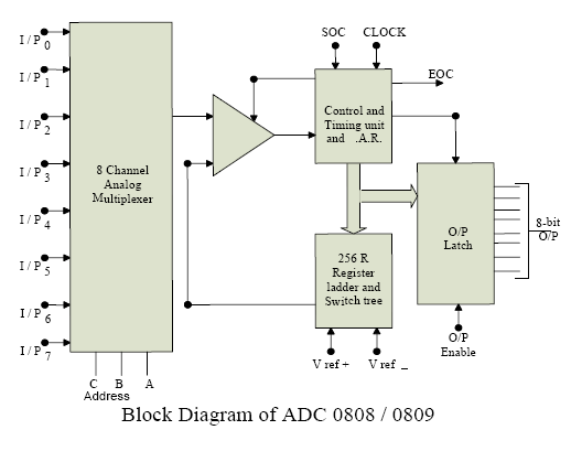
23 ADC 0808/0809 : The analog to digital converter chips 0808 and 0809 are 8-bit CMOS, successive approximation converters. This technique is one of the fast techniques for analog to digital conversion. The conversion delay is 100µs at a clock frequency of 640 KHz, which is quite low as compared to other converters. These converters do not need any external zero or full scale adjustments as they are already taken care of by internal circuits. These converters internally have a 3:8 analog multiplexer so that at a time eight different analog conversion by using address lines - ADD A, ADD B, ADD C. Using these address inputs, multichannel data acquisition system can be designed using a single ADC. The CPU may drive these lines using output port lines in case of multichannel applications. In case of single input applications, these may be hardwired to select the proper input. There are unipolar analog to digital converters, i.e. they are able to convert only positive analog input voltage to their digital equivalent. These chips do no contain any internal sample and hold circuit. 23

24 24

25 If one needs a sample and hold circuit for the conversion of fast signal into equivalent digital quantities, it has to be externally connected at each of the analog inputs. 25

26 26
27 27
28 28
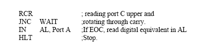
29 Example: Interfacing ADC 0808 with 8086 using 8255 ports. Use port A of 8255 for transferring digital data output of ADC to the CPU and port C for control signals. Assume that an analog input is present at I/P2 of the ADC and a clock input of suitable frequency is available for ADC. Solution: The analog input I/P2 is used and therefore address pins A,B,C should be 0,1,0 respectively to select I/P2. The OE and ALE pins are already kept at +5V to select the ADC and enable the outputs. Port C upper acts as the input port to receive the EOC signal while port C lower acts as the output port to send SOC to the ADC. Port A acts as a 8-bit input data port to receive the digital data output from the ADC. The 8255 control word is written as follows: 29
30 30
31 31
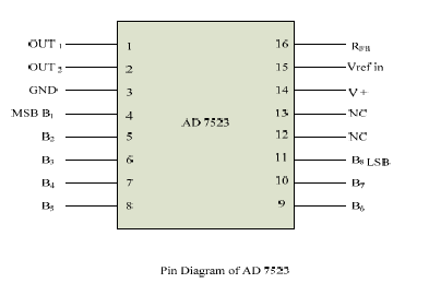
32 Interfacing Digital To Analog Converters INTERFACING DIGITAL TO ANALOG CONVERTERS: The digital to analog converters convert binary number into their equivalent voltages. The DAC find applications in areas like digitally controlled gains, motors speed controls, programmable gain amplifiers etc. AD bit Multiplying DAC : This is a 16 pin DIP, multiplying digital to analog converter, containing R-2R ladder for D-A conversion along with single pole double thrown NMOS switches to connect the digital inputs to the ladder. 32
33 33
34 The pin diagram of AD7523 is shown in fig the supply range is from +5V to +15V, while Vref may be any where between -10V to +10V. The maximum analog output voltage will be any where between -10V to +10V, when all the digital inputs are at logic high state. Usually a zener is connected between OUT1 and OUT2 to save the DAC from negative transients. An operational amplifier is used as a current to voltage converter at the output of AD to convert the current out put of AD to a proportional output voltage. It also offers additional drive capability to the DAC output. An external feedback resistor acts to control the gain. One may not connect any external feedback resistor, if no gain control is required. 34
35 EXAMPLE: Interfacing DAC AD7523 with an 8086 CPU running at 8MHZ and write an assembly language program to generate a sawtooth waveform of period 1ms with Vmax 5V. Solution: Fig shows the interfacing circuit of AD with 8086 using program gives an ALP to generate a sawtooth waveform using circuit. 35
36 36
37 37
38 In the above program, port A is initialized as the output port for sending the digital data as input to DAC. The ramp starts from the 0V (analog), hence AL starts with 00H. To increment the ramp, the content of AL is increased during each execution of loop till it reaches F2H. After that the saw tooth wave again starts from 00H, i.e. 0V(analog) and the procedure is repeated. The ramp period given by this program is precisely ms. Here the count F2H has been calculated by dividing the required delay of 1ms by the time required for the execution of the loop once. The ramp slope can be controlled by calling a controllable delay after the OUT instruction. For more Notes Follow 38
Interfacing To Alphanumeric Displays
 Interfacing To Alphanumeric Displays To give directions or data values to users, many microprocessor-controlled instruments and machines need to display letters of the alphabet and numbers. In systems
Interfacing Analog to Digital Data Converters
 Converters In most of the cases, the PIO 8255 is used for interfacing the analog to digital converters with microprocessor. We have already studied 8255 interfacing with 8086 as an I/O port, in previous
NTE2053 Integrated Circuit 8 Bit MPU Compatible A/D Converter
 NTE2053 Integrated Circuit 8 Bit MPU Compatible A/D Converter Description: The NTE2053 is a CMOS 8 bit successive approximation Analog to Digital converter in a 20 Lead DIP type package which uses a differential
AUTOMATIC NIGHT LAMP WITH MORNING ALARM USING MICROPROCESSOR
 AUTOMATIC NIGHT LAMP WITH MORNING ALARM USING MICROPROCESSOR INTRODUCTION This Project "Automatic Night Lamp with Morning Alarm" was developed using Microprocessor. It is the Heart of the system. The sensors
Features DISPLAY DECODING INPUT INTERFACING
 Data Sheet FN3158.8 4-Digit, LCD Display Driver The device is a non-multiplexed four-digit seven-segment CMOS LCD display decoder-driver. This device is configured to drive conventional LCD displays by
Hello and welcome to this training module for the STM32L4 Liquid Crystal Display (LCD) controller. This controller can be used in a wide range of
 controller. This controller can be used in a wide range of") Hello and welcome to this training module for the STM32L4 Liquid Crystal Display (LCD) controller. This controller can be used in a wide range of applications such as home appliances, medical, automotive,
Hello and welcome to this training module for the STM32L4 Liquid Crystal Display (LCD) controller. This controller can be used in a wide range of applications such as home appliances, medical, automotive,
A Digital Timer Implementation using 7 Segment Displays
 A Digital Timer Implementation using 7 Segment Displays Group Members: Tiffany Sham u2548168 Michael Couchman u4111670 Simon Oseineks u2566139 Caitlyn Young u4233209 Subject: ENGN3227 - Analogue Electronics
Controlling a Dot Matrix LED Display with a Microcontroller
 Controlling a Dot Matrix LED Display with a Microcontroller By Matt Stabile and programming will be explained in general terms as well to allow for adaptation to any comparable microcontroller or LED matrix.
Chapter 2 Logic Gates and Introduction to Computer Architecture
 Chapter 2 Logic Gates and Introduction to Computer Architecture 2.1 Introduction The basic components of an Integrated Circuit (IC) is logic gates which made of transistors, in digital system there are
The components. E3: Digital electronics. Goals:
 E3: Digital electronics Goals: Basic understanding of logic circuits. Become familiar with the most common digital components and their use. Equipment: 1 st. LED bridge 1 st. 7-segment display. 2 st. IC
Conversion Between Analog and Digital Signals
 ELET 3156 DL - Laboratory #6 Conversion Between Analog and Digital Signals There is no pre-lab work required for this experiment. However, be sure to read through the assignment completely prior to starting
Data Acquisition Module with I2C interface «I2C-FLEXEL» User s Guide
 Data Acquisition Module with I2C interface «I2C-FLEXEL» User s Guide Sensors LCD Real Time Clock/ Calendar DC Motors Buzzer LED dimming Relay control I2C-FLEXEL PS2 Keyboards Servo Motors IR Remote Control
Digital to Analog and Analog to Digital Conversion
 Real world (lab) is Computer (binary) is digital Digital to Analog and Analog to Digital Conversion V t V t D/A or DAC and A/D or ADC D/A Conversion Computer DAC A/D Conversion Computer DAC Digital to
Digital to Analog Converter. Raghu Tumati
 Digital to Analog Converter Raghu Tumati May 11, 2006 Contents 1) Introduction............................... 3 2) DAC types................................... 4 3) DAC Presented.............................
Programming Logic controllers
 Programming Logic controllers Programmable Logic Controller (PLC) is a microprocessor based system that uses programmable memory to store instructions and implement functions such as logic, sequencing,
GLOLAB Universal Telephone Hold
 GLOLAB Universal Telephone Hold 1 UNIVERSAL HOLD CIRCUIT If you have touch tone telephone service, you can now put a call on hold from any phone in the house, even from cordless phones and phones without
HD44780U (LCD-II) (Dot Matrix Liquid Crystal Display Controller/Driver)
 (Dot Matrix Liquid Crystal Display Controller/Driver)") HD4478U (LCD-II) (Dot Matrix Liquid Crystal Display Controller/Driver) Description The HD4478U dot-matrix liquid crystal display controller and driver LSI displays alphanumerics, Japanese kana characters,
HD4478U (LCD-II) (Dot Matrix Liquid Crystal Display Controller/Driver) Description The HD4478U dot-matrix liquid crystal display controller and driver LSI displays alphanumerics, Japanese kana characters,
150127-Microprocessor & Assembly Language
 Chapter 3 Z80 Microprocessor Architecture The Z 80 is one of the most talented 8 bit microprocessors, and many microprocessor-based systems are designed around the Z80. The Z80 microprocessor needs an
Chapter 6: From Digital-to-Analog and Back Again
 Chapter 6: From Digital-to-Analog and Back Again Overview Often the information you want to capture in an experiment originates in the laboratory as an analog voltage or a current. Sometimes you want to
LAB 7 MOSFET CHARACTERISTICS AND APPLICATIONS
 LAB 7 MOSFET CHARACTERISTICS AND APPLICATIONS Objective In this experiment you will study the i-v characteristics of an MOS transistor. You will use the MOSFET as a variable resistor and as a switch. BACKGROUND
Supply voltage Supervisor TL77xx Series. Author: Eilhard Haseloff
 Supply voltage Supervisor TL77xx Series Author: Eilhard Haseloff Literature Number: SLVAE04 March 1997 i IMPORTANT NOTICE Texas Instruments (TI) reserves the right to make changes to its products or to
Lecture N -1- PHYS 3330. Microcontrollers
 Lecture N -1- PHYS 3330 Microcontrollers If you need more than a handful of logic gates to accomplish the task at hand, you likely should use a microcontroller instead of discrete logic gates 1. Microcontrollers
Android based Alcohol detection system using Bluetooth technology
 For more Project details visit: http://www.projectsof8051.com/android-based-alcohol-detection-system-usingbluetooth-technology/ Code 1435 Project Title Android based Alcohol detection system using Bluetooth
Timer A (0 and 1) and PWM EE3376
 and PWM EE3376") Timer A (0 and 1) and PWM EE3376 General Peripheral Programming Model Each peripheral has a range of addresses in the memory map peripheral has base address (i.e. 0x00A0) each register used in the peripheral
Timer A (0 and 1) and PWM EE3376 General Peripheral Programming Model Each peripheral has a range of addresses in the memory map peripheral has base address (i.e. 0x00A0) each register used in the peripheral
GLOLAB Two Wire Stepper Motor Positioner
 Introduction A simple and inexpensive way to remotely rotate a display or object is with a positioner that uses a stepper motor to rotate it. The motor is driven by a circuit mounted near the motor and
Microtronics technologies Mobile: 99707 90092
 For more Project details visit: http://www.projectsof8051.com/rfid-based-attendance-management-system/ Code Project Title 1500 RFid Based Attendance System Synopsis for RFid Based Attendance System 1.
A simple RF/Microwave frequency counter
 Matjaz Vidmar, S53MV A simple RF/Microwave frequency counter I decided to design a simple, easily reproducible counter around a PIC 16F876A. The basic counter range is extended to at least 180MHz using
Micro-Step Driving for Stepper Motors: A Case Study
 Micro-Step Driving for Stepper Motors: A Case Study N. Sedaghati-Mokhtari Graduate Student, School of ECE, University of Tehran, Tehran, Iran n.sedaghati @ece.ut.ac.ir Abstract: In this paper, a case study
2011, The McGraw-Hill Companies, Inc. Chapter 3
 Chapter 3 3.1 Decimal System The radix or base of a number system determines the total number of different symbols or digits used by that system. The decimal system has a base of 10 with the digits 0 through
Decimal Number (base 10) Binary Number (base 2)
 Binary Number (base 2)") LECTURE 5. BINARY COUNTER Before starting with counters there is some vital information that needs to be understood. The most important is the fact that since the outputs of a digital chip can only be
LECTURE 5. BINARY COUNTER Before starting with counters there is some vital information that needs to be understood. The most important is the fact that since the outputs of a digital chip can only be
CHAPTER 11: Flip Flops
 CHAPTER 11: Flip Flops In this chapter, you will be building the part of the circuit that controls the command sequencing. The required circuit must operate the counter and the memory chip. When the teach
1. Oscilloscope is basically a graph-displaying device-it draws a graph of an electrical signal.
 CHAPTER 3: OSCILLOSCOPE AND SIGNAL GENERATOR 3.1 Introduction to oscilloscope 1. Oscilloscope is basically a graph-displaying device-it draws a graph of an electrical signal. 2. The graph show signal change
Op-Amp Simulation EE/CS 5720/6720. Read Chapter 5 in Johns & Martin before you begin this assignment.
 Op-Amp Simulation EE/CS 5720/6720 Read Chapter 5 in Johns & Martin before you begin this assignment. This assignment will take you through the simulation and basic characterization of a simple operational
ADC0808/ADC0809 8-Bit µp Compatible A/D Converters with 8-Channel Multiplexer
 ADC0808/ADC0809 8-Bit µp Compatible A/D Converters with 8-Channel Multiplexer General Description The ADC0808, ADC0809 data acquisition component is a monolithic CMOS device with an 8-bit analog-to-digital
Monitoring of Intravenous Drip Rate
 Monitoring of Intravenous Drip Rate Vidyadhar V. Kamble, Prem C. Pandey, Chandrashekar P. Gadgil, and Dinesh S. Choudhary Abstract A drip rate meter, for monitoring intravenous infusion, is developed using
DM9368 7-Segment Decoder/Driver/Latch with Constant Current Source Outputs
 DM9368 7-Segment Decoder/Driver/Latch with Constant Current Source Outputs General Description The DM9368 is a 7-segment decoder driver incorporating input latches and constant current output circuits
24-Bit Analog-to-Digital Converter (ADC) for Weigh Scales FEATURES S8550 VFB. Analog Supply Regulator. Input MUX. 24-bit Σ ADC. PGA Gain = 32, 64, 128
 for Weigh Scales FEATURES S8550 VFB. Analog Supply Regulator. Input MUX. 24-bit Σ ADC. PGA Gain = 32, 64, 128") 24-Bit Analog-to-Digital Converter (ADC) for Weigh Scales DESCRIPTION Based on Avia Semiconductor s patented technology, HX711 is a precision 24-bit analogto-digital converter (ADC) designed for weigh
24-Bit Analog-to-Digital Converter (ADC) for Weigh Scales DESCRIPTION Based on Avia Semiconductor s patented technology, HX711 is a precision 24-bit analogto-digital converter (ADC) designed for weigh
Drive circuit basics + V. τ e. Industrial Circuits Application Note. Winding resistance and inductance
 ndustrial Circuits Application Note Drive circuit basics For a given size of a stepper motor, a limited space is available for the windings. n the process of optimizing a stepper motor drive system, an
Digital Systems Based on Principles and Applications of Electrical Engineering/Rizzoni (McGraw Hill
 Digital Systems Based on Principles and Applications of Electrical Engineering/Rizzoni (McGraw Hill Objectives: Analyze the operation of sequential logic circuits. Understand the operation of digital counters.
ADS9850 Signal Generator Module
 1. Introduction ADS9850 Signal Generator Module This module described here is based on ADS9850, a CMOS, 125MHz, and Complete DDS Synthesizer. The AD9850 is a highly integrated device that uses advanced
HD61202U. (Dot Matrix Liquid Crystal GraphicDisplay Column Driver)
") HD622U (Dot Matrix Liquid Crystal GraphicDisplay Column Driver) Description HD622U is a column (segment) driver for dot matrix liquid crystal graphic display systems. It stores the display data transferred
HD622U (Dot Matrix Liquid Crystal GraphicDisplay Column Driver) Description HD622U is a column (segment) driver for dot matrix liquid crystal graphic display systems. It stores the display data transferred
RAM & ROM Based Digital Design. ECE 152A Winter 2012
 RAM & ROM Based Digital Design ECE 152A Winter 212 Reading Assignment Brown and Vranesic 1 Digital System Design 1.1 Building Block Circuits 1.1.3 Static Random Access Memory (SRAM) 1.1.4 SRAM Blocks in
SECTION C [short essay] [Not to exceed 120 words, Answer any SIX questions. Each question carries FOUR marks] 6 x 4=24 marks
![SECTION C [short essay] [Not to exceed 120 words, Answer any SIX questions. Each question carries FOUR marks] 6 x 4=24 marks](/thumbs/35/17285180.jpg "SECTION C [short essay] [Not to exceed 120 words, Answer any SIX questions. Each question carries FOUR marks] 6 x 4=24 marks") UNIVERSITY OF KERALA First Degree Programme in Computer Applications Model Question Paper Semester I Course Code- CP 1121 Introduction to Computer Science TIME : 3 hrs Maximum Mark: 80 SECTION A [Very
UNIVERSITY OF KERALA First Degree Programme in Computer Applications Model Question Paper Semester I Course Code- CP 1121 Introduction to Computer Science TIME : 3 hrs Maximum Mark: 80 SECTION A [Very
White Paper Thin-Film-Transistor (TFT) LCD Display Control Electronics Design and Operation Revision 1.0
 LCD Display Control Electronics Design and Operation Revision 1.0") White Paper Thin-Film-Transistor (TFT) LCD Display Control Electronics Design and Operation Revision 1.0 TABLE OF CONTENTS 1 TFT OVERVIEW...3 2 TFT CONTROLLER LOGIC...5 2.1 DRIVERS-ONLY TFT LCD DISPLAYS...5
White Paper Thin-Film-Transistor (TFT) LCD Display Control Electronics Design and Operation Revision 1.0 TABLE OF CONTENTS 1 TFT OVERVIEW...3 2 TFT CONTROLLER LOGIC...5 2.1 DRIVERS-ONLY TFT LCD DISPLAYS...5
Accurate Measurement of the Mains Electricity Frequency
 Accurate Measurement of the Mains Electricity Frequency Dogan Ibrahim Near East University, Faculty of Engineering, Lefkosa, TRNC dogan@neu.edu.tr Abstract The frequency of the mains electricity supply
A+ Guide to Managing and Maintaining Your PC, 7e. Chapter 1 Introducing Hardware
 A+ Guide to Managing and Maintaining Your PC, 7e Chapter 1 Introducing Hardware Objectives Learn that a computer requires both hardware and software to work Learn about the many different hardware components
DS12885, DS12885Q, DS12885T. Real Time Clock FEATURES PIN ASSIGNMENT
 DS12885, DS12885Q, DS12885T Real Time Clock FEATURES Drop in replacement for IBM AT computer clock/calendar Pin configuration closely matches MC146818B and DS1285 Counts seconds, minutes, hours, days,
3-Phase Synchronous PWM Controller IC Provides an Integrated Solution for Intel VRM 9.0 Design Guidelines
 3-Phase Synchronous PWM Controller IC Provides an Integrated Solution for Intel VRM 9.0 Design Guidelines Odile Ronat International Rectifier The fundamental reason for the rapid change and growth in information
MICROPROCESSOR AND MICROCOMPUTER BASICS
 Introduction MICROPROCESSOR AND MICROCOMPUTER BASICS At present there are many types and sizes of computers available. These computers are designed and constructed based on digital and Integrated Circuit
Having read this workbook you should be able to: recognise the arrangement of NAND gates used to form an S-R flip-flop.
 Objectives Having read this workbook you should be able to: recognise the arrangement of NAND gates used to form an S-R flip-flop. describe how such a flip-flop can be SET and RESET. describe the disadvantage
Display Driver Family Combines Convenience of Use with Microprocessor Interfaceability
 Display Driver Family Combines Convenience of Use with Microprocessor Interfaceability Application Note AN054 Authors: Peter Bradshaw and Dan Watson Introduction For some time now Intersil has manufactured
THE BASICS OF PLL FREQUENCY SYNTHESIS
 Supplementary Reading for 27 - Oscillators Ron Bertrand VK2DQ http://www.radioelectronicschool.com THE BASICS OF PLL FREQUENCY SYNTHESIS The phase locked loop (PLL) method of frequency synthesis is now
Microcontroller Based Low Cost Portable PC Mouse and Keyboard Tester
 Leonardo Journal of Sciences ISSN 1583-0233 Issue 20, January-June 2012 p. 31-36 Microcontroller Based Low Cost Portable PC Mouse and Keyboard Tester Ganesh Sunil NHIVEKAR *, and Ravidra Ramchandra MUDHOLKAR
COMBINATIONAL and SEQUENTIAL LOGIC CIRCUITS Hardware implementation and software design
 PH-315 COMINATIONAL and SEUENTIAL LOGIC CIRCUITS Hardware implementation and software design A La Rosa I PURPOSE: To familiarize with combinational and sequential logic circuits Combinational circuits
LM 358 Op Amp. If you have small signals and need a more useful reading we could amplify it using the op amp, this is commonly used in sensors.
 LM 358 Op Amp S k i l l L e v e l : I n t e r m e d i a t e OVERVIEW The LM 358 is a duel single supply operational amplifier. As it is a single supply it eliminates the need for a duel power supply, thus
Low Power AMD Athlon 64 and AMD Opteron Processors
 Low Power AMD Athlon 64 and AMD Opteron Processors Hot Chips 2004 Presenter: Marius Evers Block Diagram of AMD Athlon 64 and AMD Opteron Based on AMD s 8 th generation architecture AMD Athlon 64 and AMD
A Lesson on Digital Clocks, One Shots and Counters
 A Lesson on Digital Clocks, One Shots and Counters Topics Clocks & Oscillators LM 555 Timer IC Crystal Oscillators Selection of Variable Resistors Schmitt Gates Power-On Reset Circuits One Shots Counters
Counters and Decoders
 Physics 3330 Experiment #10 Fall 1999 Purpose Counters and Decoders In this experiment, you will design and construct a 4-bit ripple-through decade counter with a decimal read-out display. Such a counter
COMBINATIONAL CIRCUITS
 COMBINATIONAL CIRCUITS http://www.tutorialspoint.com/computer_logical_organization/combinational_circuits.htm Copyright tutorialspoint.com Combinational circuit is a circuit in which we combine the different
Build A Video Switcher. Reprinted with permission from Electronics Now Magazine September 1997 issue
 Build A Video Switcher Reprinted with permission from Electronics Now Magazine September 1997 issue Copyright Gernsback Publications, Inc.,1997 BUILD A VIDEO SWITCHER FRANK MONTEGARI Watch several cameras
3-Phase DC Brushless Motor Pre-Drivers Technical Information NJM2625A
 3Phase DC Brushless Motor PreDrivers 1.FEATURE NJM2625 is a controller and predriver for speed control 3phase blushless DC motor. The device provides the proper sequencing of 3phase drive output with external
A Lesson on Digital Clocks, One Shots and Counters
 A Lesson on Digital Clocks, One Shots and Counters Topics Clocks & Oscillators LM 555 Timer IC Crystal Oscillators Selection of Variable Resistors Schmitt Gates Power-On Reset Circuits One Shots Counters
8051 hardware summary
 8051 hardware summary 8051 block diagram 8051 pinouts + 5V ports port 0 port 1 port 2 port 3 : dual-purpose (general-purpose, external memory address and data) : dedicated (interfacing to external devices)
Simple PWM Boost Converter with I/O Disconnect Solves Malfunctions Caused when V OUT <V IN
 Simple PWM Boost Converter with I/O Disconnect Solves Malfunctions Caused when V OUT
Zero voltage drop synthetic rectifier
 Zero voltage drop synthetic rectifier Vratislav Michal Brno University of Technology, Dpt of Theoretical and Experimental Electrical Engineering Kolejní 4/2904, 612 00 Brno Czech Republic vratislav.michal@gmail.com,
4 Character 5x7 LED Matrix Display
 Mini project report on 4 Character 5x7 LED Matrix Display Submitted by Agarwal Vikas, MTech II, CEDT K.Sreenivasulu M.E (Micro) II, CEDT CENTRE FOR ELECTRONICS DESIGN AND TECHNOLOGY INDIAN INSTITUTE OF
Pulse Width Modulation
 Pulse Width Modulation Pulse width modulation (PWM) is a powerful technique for controlling analog circuits with a microprocessor's digital outputs. PWM is employed in a wide variety of applications, ranging
3-Digit Counter and Display
 ECE 2B Winter 2007 Lab #7 7 3-Digit Counter and Display This final lab brings together much of what we have done in our lab experiments this quarter to construct a simple tachometer circuit for measuring
STEPPER MOTOR SPEED AND POSITION CONTROL
 STEPPER MOTOR SPEED AND POSITION CONTROL Group 8: Subash Anigandla Hemanth Rachakonda Bala Subramanyam Yannam Sri Divya Krovvidi Instructor: Dr. Jens - Peter Kaps ECE 511 Microprocessors Fall Semester
Display Board Pulse Width Modulation (PWM) Power/Speed Controller Module
 Power/Speed Controller Module") Display Board Pulse Width Modulation (PWM) Power/Speed Controller Module RS0 Microcontroller LEDs Motor Control Pushbuttons Purpose: To demonstrate an easy way of using a Freescale RS0K2 microcontroller
Display Board Pulse Width Modulation (PWM) Power/Speed Controller Module RS0 Microcontroller LEDs Motor Control Pushbuttons Purpose: To demonstrate an easy way of using a Freescale RS0K2 microcontroller
The full wave rectifier consists of two diodes and a resister as shown in Figure
 The Full-Wave Rectifier The full wave rectifier consists of two diodes and a resister as shown in Figure The transformer has a centre-tapped secondary winding. This secondary winding has a lead attached
AP-1 Application Note on Remote Control of UltraVolt HVPS
 Basics Of UltraVolt HVPS Output Voltage Control Application Note on Remote Control of UltraVolt HVPS By varying the voltage at the Remote Adjust Input terminal (pin 6) between 0 and +5V, the UV highvoltage
Fundamentals of Signature Analysis
 Fundamentals of Signature Analysis An In-depth Overview of Power-off Testing Using Analog Signature Analysis www.huntron.com 1 www.huntron.com 2 Table of Contents SECTION 1. INTRODUCTION... 7 PURPOSE...
FEATURES DESCRIPTION. PT6321 Fluorescent Display Tube Controller Driver
 Fluorescent Display Tube Controller Driver DESCRIPTION The PT6321 is a dot matrix fluorescent display tube controller driver IC which displays characters, numerics and symbols. Dot matrix fluorescent display
Upon completion of unit 1.1, students will be able to
 Upon completion of unit 1.1, students will be able to 1. Demonstrate safety of the individual, class, and overall environment of the classroom/laboratory, and understand that electricity, even at the nominal
Transistor Amplifiers
 Physics 3330 Experiment #7 Fall 1999 Transistor Amplifiers Purpose The aim of this experiment is to develop a bipolar transistor amplifier with a voltage gain of minus 25. The amplifier must accept input
Operating Manual Ver.1.1
 4 Bit Binary Ripple Counter (Up-Down Counter) Operating Manual Ver.1.1 An ISO 9001 : 2000 company 94-101, Electronic Complex Pardesipura, Indore- 452010, India Tel : 91-731- 2570301/02, 4211100 Fax: 91-731-
Digital Sampling Oscilloscope
 Digital Sampling Oscilloscope Mary Anne Peters & Joseph Tylka Department of Mechanical and Aerospace Engineering Princeton University, Princeton, NJ 8, USA INTRODUCTION This paper summarizes the construction
Adding Heart to Your Technology
 RMCM-01 Heart Rate Receiver Component Product code #: 39025074 KEY FEATURES High Filtering Unit Designed to work well on constant noise fields SMD component: To be installed as a standard component to
DIGITAL-TO-ANALOGUE AND ANALOGUE-TO-DIGITAL CONVERSION
 DIGITAL-TO-ANALOGUE AND ANALOGUE-TO-DIGITAL CONVERSION Introduction The outputs from sensors and communications receivers are analogue signals that have continuously varying amplitudes. In many systems
Graphical displays are generally of two types: vector displays and raster displays. Vector displays
 Display technology Graphical displays are generally of two types: vector displays and raster displays. Vector displays Vector displays generally display lines, specified by their endpoints. Vector display
Programmable Single-/Dual-/Triple- Tone Gong SAE 800
 Programmable Single-/Dual-/Triple- Tone Gong Preliminary Data SAE 800 Bipolar IC Features Supply voltage range 2.8 V to 18 V Few external components (no electrolytic capacitor) 1 tone, 2 tones, 3 tones
Operational Amplifier - IC 741
 Operational Amplifier - IC 741 Tabish December 2005 Aim: To study the working of an 741 operational amplifier by conducting the following experiments: (a) Input bias current measurement (b) Input offset
AMZ-FX Guitar effects. (2007) Mosfet Body Diodes. http://www.muzique.com/news/mosfet-body-diodes/. Accessed 22/12/09.
 Mosfet Body Diodes. http://www.muzique.com/news/mosfet-body-diodes/. Accessed 22/12/09.") Pulse width modulation Pulse width modulation is a pulsed DC square wave, commonly used to control the on-off switching of a silicon controlled rectifier via the gate. There are many types of SCR s, most
Pulse width modulation Pulse width modulation is a pulsed DC square wave, commonly used to control the on-off switching of a silicon controlled rectifier via the gate. There are many types of SCR s, most
MAS.836 HOW TO BIAS AN OP-AMP
 MAS.836 HOW TO BIAS AN OP-AMP Op-Amp Circuits: Bias, in an electronic circuit, describes the steady state operating characteristics with no signal being applied. In an op-amp circuit, the operating characteristic
css Custom Silicon Solutions, Inc.
 css Custom Silicon Solutions, Inc. CSS555(C) CSS555/ PART DESCRIPTION The CSS555 is a micro-power version of the popular 555 Timer IC. It is pin-for-pin compatible with the standard 555 timer and features
NT7606. STN LCDController/Driver. RAM-Map STN LCD Controller/Driver. Preliminary
 16C Characters X 3L Character X 3 Lines + 80 + icon 80 icons RAM-Map STN LCD Controller/Driver STN LCDController/Driver V0.04 V1.0 Preliminary Revision History...3 Features...4 General Description...4
Use and Application of Output Limiting Amplifiers (HFA1115, HFA1130, HFA1135)
") Use and Application of Output Limiting Amplifiers (HFA111, HFA110, HFA11) Application Note November 1996 AN96 Introduction Amplifiers with internal voltage clamps, also known as limiting amplifiers, have
Use and Application of Output Limiting Amplifiers (HFA111, HFA110, HFA11) Application Note November 1996 AN96 Introduction Amplifiers with internal voltage clamps, also known as limiting amplifiers, have
Section 3. Sensor to ADC Design Example
 Section 3 Sensor to ADC Design Example 3-1 This section describes the design of a sensor to ADC system. The sensor measures temperature, and the measurement is interfaced into an ADC selected by the systems
Power Supplies. 1.0 Power Supply Basics. www.learnabout-electronics.org. Module
 Module 1 www.learnabout-electronics.org Power Supplies 1.0 Power Supply Basics What you ll learn in Module 1 Section 1.0 Power Supply Basics. Basic functions of a power supply. Safety aspects of working
ETEC 421 - Digital Controls PIC Lab 10 Pulse Width Modulation
 ETEC 421 - Digital Controls PIC Lab 10 Pulse Width Modulation Program Definition: Write a program to control the speed of a dc motor using pulse width modulation. Discussion: The speed of a dc motor is
DEPARTMENT OF COMPUTER SCIENCE & ENGINEERING Question Bank Subject Name: EC6504 - Microprocessor & Microcontroller Year/Sem : II/IV
 DEPARTMENT OF COMPUTER SCIENCE & ENGINEERING Question Bank Subject Name: EC6504 - Microprocessor & Microcontroller Year/Sem : II/IV UNIT I THE 8086 MICROPROCESSOR 1. What is the purpose of segment registers
PROGRAMMABLE LOGIC CONTROLLERS Unit code: A/601/1625 QCF level: 4 Credit value: 15 TUTORIAL OUTCOME 2 Part 1
 UNIT 22: PROGRAMMABLE LOGIC CONTROLLERS Unit code: A/601/1625 QCF level: 4 Credit value: 15 TUTORIAL OUTCOME 2 Part 1 This work covers part of outcome 2 of the Edexcel standard module. The material is
POCKET SCOPE 2. The idea 2. Design criteria 3
 POCKET SCOPE 2 The idea 2 Design criteria 3 Microcontroller requirements 3 The microcontroller must have speed. 3 The microcontroller must have RAM. 3 The microcontroller must have secure Flash. 3 The
CHAPTER 16 MEMORY CIRCUITS
 CHPTER 6 MEMORY CIRCUITS Chapter Outline 6. atches and Flip-Flops 6. Semiconductor Memories: Types and rchitectures 6.3 Random-ccess Memory RM Cells 6.4 Sense-mplifier and ddress Decoders 6.5 Read-Only
MICROPROCESSOR. Exclusive for IACE Students www.iace.co.in iacehyd.blogspot.in Ph: 9700077455/422 Page 1
 MICROPROCESSOR A microprocessor incorporates the functions of a computer s central processing unit (CPU) on a single Integrated (IC), or at most a few integrated circuit. It is a multipurpose, programmable
8-Bit Flash Microcontroller for Smart Cards. AT89SCXXXXA Summary. Features. Description. Complete datasheet available under NDA
 Features Compatible with MCS-51 products On-chip Flash Program Memory Endurance: 1,000 Write/Erase Cycles On-chip EEPROM Data Memory Endurance: 100,000 Write/Erase Cycles 512 x 8-bit RAM ISO 7816 I/O Port
HT9170 DTMF Receiver. Features. General Description. Selection Table
 DTMF Receiver Features Operating voltage: 2.5V~5.5V Minimal external components No external filter is required Low standby current (on power down mode) General Description The HT9170 series are Dual Tone
Study Guide for the Electronics Technician Pre-Employment Examination
 Bay Area Rapid Transit District Study Guide for the Electronics Technician Pre-Employment Examination INTRODUCTION The Bay Area Rapid Transit (BART) District makes extensive use of electronics technology