Introduction to Basic Electronics 7
|
|
|
- Cora Pierce
- 7 years ago
- Views:
Transcription
1 Introduction to Basic Electronics 7
2 Basic Electronics Oscillator - Introduction - Resonance - Hartley Oscillator - Colpitts Oscillator - RC Oscillator
3 Introduction to Oscillator Oscillators are used in many electronic circuits and systems providing the central "clock" signal that controls the sequential operation of the entire system. Oscillators can produce a wide range of different wave shapes and frequencies that can be complicated or simple depending upon the application. Oscillators are also used in many pieces of test equipment producing either sinusoidal sine waves, square, sawtooth or triangular shaped waveforms or just pulses of a variable or constant width.
4 Introduction to Oscillator Oscillators are basically an Amplifier with "Positive Feedback", (inphase) and one of the many problems in electronic circuit design is stopping amplifiers from oscillating while trying to get oscillators to oscillate. Oscillators works because they overcome the losses of their feedback resonator circuit either in the form of a Capacitor, Inductor or both by applying DC energy at the required frequency into this resonator circuit. Then an Oscillator has a gain equal too or slightly greater than 1. In addition to these reactive components, an amplifying device such as an Operational Amplifier or Bipolar Transistor is required. Unlike an amplifier there is no external AC input required to cause the Oscillator to work as the DC supply energy is converted by the oscillator into AC energy at the required frequency.
5 Introduction to Oscillator Basic Feedback Circuit
6 Introduction to Oscillator Oscillators are circuits that generate a continuous voltage output waveform at a required frequency with the values of the inductors, capacitors or resistors forming a frequency selective LC resonant (or tank) feedback network. The oscillators frequency is controlled using a tuned or resonant inductive/capacitive (LC) circuit with the resulting output frequency being known as the Oscillation Frequency and by making the oscillators feedback a reactive network the phase angle of the feedback will vary as a function of frequency and this is called Phase-shift.
7 Introduction to Oscillator There are basically types of Oscillators. 1. Sinusoidal Oscillators - These are known as Harmonic Oscillators and are generally a "LC Tuned-feedback" or "RC tuned-feedback" type Oscillator that generates a sinusoidal waveform which is of constant amplitude and frequency. 2. Non-Sinusoidal Oscillators - These are known as Relaxation Oscillators and generate complex non- sinusoidal waveforms that changes very quickly from one condition of stability to another such as "Square-wave", "Triangularwave" or "Sawtoothed-wave" type waveforms.
8 Resonance When a constant voltage but of varying frequency is applied to a circuit consisting of an inductor, capacitor and resistor the reactance of both the Capacitor/Resistor and Inductor/Resistor circuits is to change both the amplitude and the phase of the output signal as compared to the input signal due to the reactance of the components used. At high frequencies the reactance of a capacitor is very low acting as a short circuit while the reactance of the inductor is high acting as an open circuit. At low frequencies the reverse is true, the reactance of the capacitor acts as an open circuit and the reactance of the inductor acts as a short circuit.
9 Resonance Between these two extremes the combination of the inductor and capacitor produces a "Tuned" or "Resonant" circuit that has a Resonant Frequency, ( ƒr ) in which the capacitive and inductive reactance's are equaland cancel out each other, leaving only the resistance of the circuit to oppose the flow of current. This means that there is no phase shift as the current is in phase with the voltage. Consider the circuit below. Basic LC Oscillatory Circuit
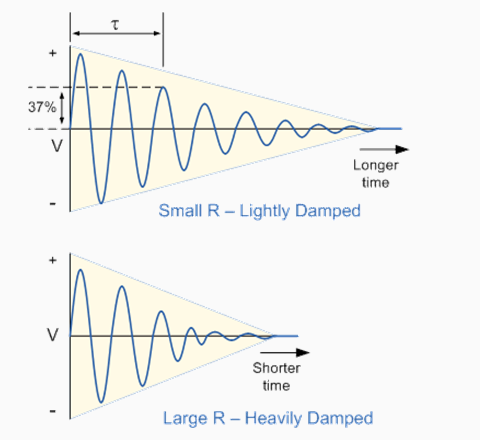
10 Damped Oscillation
11 Damped Oscillation The losses are mainly due to the resistance of the inductors windings called the "Real Resistance". If this real resistance is low the oscillations will die away slowly and if the coil resistance is high the oscillations die away more rapidly. The frequency of the oscillatory voltage depends upon the value of the inductance and capacitance in the LC circuit. We know that for Resonance to occur both the capacitive, X C and inductive, X L reactance's must be equal, X L = X C and opposite to cancel out each other out leaving only the resistance in the circuit to oppose the flow of current.
12 Damped Oscillation Then the frequency at which this will happen is given as:

13 Damped Oscillation Then by simplifying the equation we get the final equation for Resonant Frequency in a tuned LC circuit as: Where: L is the Inductance in Henrys C is the Capacitance in Farads fr is the Output Frequency in Hertz This equation shows that if either L or C are decreased, the frequency increases. This output frequency is commonly given the abbreviation of ( fr ) to identify it as the Resonant Frequency
14 Oscillator Summary The basic requirements for an Oscillatory circuit are given as follows. 1. The circuit MUST contain a reactive (frequency-dependant) component either an Inductor, (L) or a Capacitor, (C) and a DC supply voltage. 2. In a simple circuit oscillations become damped due to circuit losses. 3. Voltage amplification is required to overcome these circuit losses. 4. The overall gain of the amplifier must be at least 1, unity. 5. Oscillations can be maintained by feeding back some of the output voltage to the tuned circuit that is of the correct amplitude and in-phase.
15 Oscillator Summary 6. Oscillations can only occur when the feedback is "Positive" (selfregeneration). 7. The overall phase shift of the circuit must be zero or 360 o so that the output signal from the feedback network will be "In-phase" with the input signal.
16 Hartley Oscillator When the circuit is oscillating, the voltage at point X (collector), relative to point Y (emitter), is 180 o out-of-phase with the voltage at point Z (base) relative to point Y. At the frequency of oscillation, the impedance of the Collector load is resistive and an increase in Base voltage causes a decrease in the Collector voltage. Then there is a 180 o phase change in the voltage between the Base and Collector and this along with the original 180 o phase shift in the feedback loop provides the correct phase relationship of positive feedback for oscillations to be maintained.
17 Hartley Oscillator The amount of feedback depends upon the position of the "tapping point" of the inductor. If this is moved nearer to the collector the amount of feedback is increased, but the output taken between the Collector and earth is reduced and vice versa. Resistors, R1 and R2 provide the usual stabilizing DC bias for the transistor in the normal manner while the capacitors act as DC-blocking capacitors.
18 Hartley Oscillator In this Hartley Oscillator circuit, the DC Collector current flows through part of the coil and for this reason the circuit is said to be "Series-fed" with the frequency of oscillation of the Hartley Oscillator being given as. Note: L T is the total inductance if two separate coils are used. The frequency of oscillations can be adjusted by varying the "tuning" capacitor, C or by varying the position of the iron-dust core inside the coil (inductive tuning) giving an output over a wide range of frequencies making it very easy to tune. Also the Hartley Oscillator produces an output amplitude which is constant over the entire frequency range.
19 Colpitts Oscillator In some ways the Colpitts Oscillator is the opposite to the Hartley Oscillator. Like the Hartley oscillator, the tuned tank circuit consists of an LC resonance circuit connected between the Collector and Base of the transistor amplifier. The basic configuration of the Colpitts Oscillator resembles that of the Hartley Oscillator but the difference being is that the centre tapping is now made from a "Capacitive Voltage Divider" network instead of a tapped autotransformer type inductor as shown below.
20 Colpitts Oscillator The transistor amplifiers Emitter is connected to the junction of capacitors, C1 and C2 which are connected in series with the required external phase shift is obtained in a similar manner to that in the Hartley Oscillator. The amount of feedback is determined by the ratio of C1 and C2 which are generally "ganged" together to provide a constant amount of feedback.
21 Colpitts Oscillator The frequency of oscillations for a Colpitts Oscillator is determined by the resonant frequency of the LC tank circuit and is given as:
22 RC Oscillator A single stage amplifier will produce 180 o of phase shift between its output and input signals when connected in a class-a configuration. For an oscillator to oscillate sufficient feedback of the correct phase, ie "Positive Feedback" must be provided with the amplifier being used as an inverting stage to achieve this. In a RC Oscillator the input is shifted 180 o through the amplifier stage and 180 o again through a second inverting stage giving us "180 o o = 360 o " of phase shift which is the same as 0 o thereby giving us the required positive feedback. In a Resistance-Capacitance Oscillator or simply an RC Oscillator, we make use of the fact that a phase shift occurs between the input to a RC network and the output from the same network.
23 RC Oscillator RC Phase-Shift Network

24 RC Oscillator The circuit on the left shows a single Resistor-Capacitor network and whose output voltage "leads" the input voltage by some angle less than 90 o. An ideal RC circuit would produce a phase shift of exactly 90 o. The amount of actual phase shift in the circuit depends upon the values of the Resistor, Capacitor and the chosen frequency of oscillations with the phase angle ( Φ ) being given as;
25 RC Oscillator Basic RC Oscillator Circuit
26 RC Oscillator The RC Oscillator which is sometimes called a Phase Shift Oscillator, produces a sine wave output signal using regenerative feedback from the Resistor/Capacitor combination. This regenerative feedback from the RC network is due to the ability of the capacitor to store an electric charge, (similar to the LC tank circuit). This Resistor/Capacitor feedback network can be connected as shown above to produce a leading phase shift (Phase Advance Network) or interchanged to produce a lagging phase shift (Phase Retard Network) the outcome is still the same as the sine wave oscillations only occur at the frequency at which the overall phaseshift is 360 o.

27 RC Oscillator By varying one or more of the resistors or capacitors in the phaseshift network, the frequency can be varied and generally this is done using a 3-ganged variable capacitor. If all the resistors, R and the capacitors, C are equal in value, then the frequency of oscillations produced by the oscillator is given as: Where: f is the Output Frequency in Hertz R is the Resistance in Ohms C is the Capacitance in Farads N is the number of RC stages and in our example N = 3
5B5BBasic RC Oscillator Circuit
 5B5BBasic RC Oscillator Circuit The RC Oscillator which is also called a Phase Shift Oscillator, produces a sine wave output signal using regenerative feedback from the resistor-capacitor combination.
Oscillators. 2.0 RF Sine Wave Oscillators. www.learnabout-electronics.org. Module. RF Oscillators
 Module 2 www.learnabout-electronics.org Oscillators 2.0 RF Sine Wave Oscillators What you ll Learn in Module 2 Section 2.0 High Frequency Sine Wave Oscillators. Frequency Control in RF Oscillators. LC
Sinusoidal. Oscillators
 364 4 Principles of Electronics Sinusoidal Oscillators 4. Sinusoidal Oscillator 4.2 Types of Sinusoidal Oscillations 4.3 Oscillatory Circuit 4.4 Undamped Oscillations from Tank Circuit 4.5 Positive Feedback
Circuits with inductors and alternating currents. Chapter 20 #45, 46, 47, 49
 Circuits with inductors and alternating currents Chapter 20 #45, 46, 47, 49 RL circuits Ch. 20 (last section) Symbol for inductor looks like a spring. An inductor is a circuit element that has a large
Effect of Frequency on Inductive Reactance
 TUNED CIRCUITS Effect of Frequency on Inductive Reactance Resonance The ideal series-resonant circuit How the Parallel-LC Circuit Stores Energy Parallel resonance Resonant circuits as filter circuits Pulsed
Single Transistor FM Transmitter Design
 Single Transistor FM Transmitter Design In telecommunications, frequency modulation (FM) conveys information over a carrier wave by varying its frequency. FM is commonly used at VHF radio frequencies for
Line Reactors and AC Drives
 Line Reactors and AC Drives Rockwell Automation Mequon Wisconsin Quite often, line and load reactors are installed on AC drives without a solid understanding of why or what the positive and negative consequences
Diodes have an arrow showing the direction of the flow.
 The Big Idea Modern circuitry depends on much more than just resistors and capacitors. The circuits in your computer, cell phone, Ipod depend on circuit elements called diodes, inductors, transistors,
Inductors in AC Circuits
 Inductors in AC Circuits Name Section Resistors, inductors, and capacitors all have the effect of modifying the size of the current in an AC circuit and the time at which the current reaches its maximum
Oscillations and Regenerative Amplification using Negative Resistance Devices
 Oscillations and Regenerative Amplification using Negative Resistance Devices Ramon Vargas Patron rvargas@inictel.gob.pe INICTEL The usual procedure for the production of sustained oscillations in tuned
Transistor Characteristics and Single Transistor Amplifier Sept. 8, 1997
 Physics 623 Transistor Characteristics and Single Transistor Amplifier Sept. 8, 1997 1 Purpose To measure and understand the common emitter transistor characteristic curves. To use the base current gain
Application Guide. Power Factor Correction (PFC) Basics
 Basics") Power Factor Correction (PFC) Basics Introduction Power Factor, in simple terms, is a number between zero and one that represents the ratio of the real power to apparent power. Real power (P), measured
Power Factor Correction (PFC) Basics Introduction Power Factor, in simple terms, is a number between zero and one that represents the ratio of the real power to apparent power. Real power (P), measured
Impedance Matching and Matching Networks. Valentin Todorow, December, 2009
 Impedance Matching and Matching Networks Valentin Todorow, December, 2009 RF for Plasma Processing - Definition of RF What is RF? The IEEE Standard Dictionary of Electrical and Electronics Terms defines
EDEXCEL NATIONAL CERTIFICATE/DIPLOMA UNIT 5 - ELECTRICAL AND ELECTRONIC PRINCIPLES NQF LEVEL 3 OUTCOME 4 - ALTERNATING CURRENT
 EDEXCEL NATIONAL CERTIFICATE/DIPLOMA UNIT 5 - ELECTRICAL AND ELECTRONIC PRINCIPLES NQF LEVEL 3 OUTCOME 4 - ALTERNATING CURRENT 4 Understand single-phase alternating current (ac) theory Single phase AC
Lecture 24. Inductance and Switching Power Supplies (how your solar charger voltage converter works)
") Lecture 24 Inductance and Switching Power Supplies (how your solar charger voltage converter works) Copyright 2014 by Mark Horowitz 1 Roadmap: How Does This Work? 2 Processor Board 3 More Detailed Roadmap
Lecture 24 Inductance and Switching Power Supplies (how your solar charger voltage converter works) Copyright 2014 by Mark Horowitz 1 Roadmap: How Does This Work? 2 Processor Board 3 More Detailed Roadmap
GenTech Practice Questions
 GenTech Practice Questions Basic Electronics Test: This test will assess your knowledge of and ability to apply the principles of Basic Electronics. This test is comprised of 90 questions in the following
Constructing a precision SWR meter and antenna analyzer. Mike Brink HNF, Design Technologist.
 Constructing a precision SWR meter and antenna analyzer. Mike Brink HNF, Design Technologist. Abstract. I have been asked to put together a detailed article on a SWR meter. In this article I will deal
BASIC ELECTRONICS AC CIRCUIT ANALYSIS. December 2011
 AM 5-202 BASIC ELECTRONICS AC CIRCUIT ANALYSIS December 2011 DISTRIBUTION RESTRICTION: Approved for Pubic Release. Distribution is unlimited. DEPARTMENT OF THE ARMY MILITARY AUXILIARY RADIO SYSTEM FORT
Chapter 12: The Operational Amplifier
 Chapter 12: The Operational Amplifier 12.1: Introduction to Operational Amplifier (Op-Amp) Operational amplifiers (op-amps) are very high gain dc coupled amplifiers with differential inputs; they are used
Power Supplies. 1.0 Power Supply Basics. www.learnabout-electronics.org. Module
 Module 1 www.learnabout-electronics.org Power Supplies 1.0 Power Supply Basics What you ll learn in Module 1 Section 1.0 Power Supply Basics. Basic functions of a power supply. Safety aspects of working
Lecture 24: Oscillators. Clapp Oscillator. VFO Startup
 Whites, EE 322 Lecture 24 Page 1 of 10 Lecture 24: Oscillators. Clapp Oscillator. VFO Startup Oscillators are circuits that produce periodic output voltages, such as sinusoids. They accomplish this feat
Lecture - 4 Diode Rectifier Circuits
 Basic Electronics (Module 1 Semiconductor Diodes) Dr. Chitralekha Mahanta Department of Electronics and Communication Engineering Indian Institute of Technology, Guwahati Lecture - 4 Diode Rectifier Circuits
Positive Feedback and Oscillators
 Physics 3330 Experiment #6 Fall 1999 Positive Feedback and Oscillators Purpose In this experiment we will study how spontaneous oscillations may be caused by positive feedback. You will construct an active
Power Amplifiers. Introduction to Power Amplifiers. Amplifiers. Module 5
 Module 5 Amplifiers Introduction to What you ll learn in Module 5. Section 5.0 Introduction to. Understand the Operation of. Section 5.1 Power Transistors & Heat Sinks. Power Transistor Construction. Power
Local Oscillator for FM broadcast band 88-108 MHz
 Local Oscillator for FM broadcast band 88-108 MHz Wang Luhao Yan Shubo Supervisor: Göran Jönsson Department of Electrical and Information Technology Lund University 2012.05.15 Abstract In this project
Current and Temperature Ratings
 Document 361-1 Current and Temperature Ratings Introduction This application note describes: How to interpret Coilcraft inductor current and temperature ratings Our current ratings measurement method and
LM 358 Op Amp. If you have small signals and need a more useful reading we could amplify it using the op amp, this is commonly used in sensors.
 LM 358 Op Amp S k i l l L e v e l : I n t e r m e d i a t e OVERVIEW The LM 358 is a duel single supply operational amplifier. As it is a single supply it eliminates the need for a duel power supply, thus
Physics 623 Transistor Characteristics and Single Transistor Amplifier Sept. 13, 2006
 Physics 623 Transistor Characteristics and Single Transistor Amplifier Sept. 13, 2006 1 Purpose To measure and understand the common emitter transistor characteristic curves. To use the base current gain
Critical thin-film processes such as deposition and etching take place in a vacuum
 WHITEPAPER INTRODUCING POWER SUPPLIES AND PLASMA Critical thin-film processes such as deposition and etching take place in a vacuum SYSTEMS chamber in the presence of a plasma. A plasma is an electrically
Electronics. Discrete assembly of an operational amplifier as a transistor circuit. LD Physics Leaflets P4.2.1.1
 Electronics Operational Amplifier Internal design of an operational amplifier LD Physics Leaflets Discrete assembly of an operational amplifier as a transistor circuit P4.2.1.1 Objects of the experiment
Unit/Standard Number. High School Graduation Years 2010, 2011 and 2012
 1 Secondary Task List 100 SAFETY 101 Demonstrate an understanding of State and School safety regulations. 102 Practice safety techniques for electronics work. 103 Demonstrate an understanding of proper
2. A conductor of length 2m moves at 4m/s at 30 to a uniform magnetic field of 0.1T. Which one of the following gives the e.m.f. generated?
 Extra Questions - 2 1. A straight length of wire moves through a uniform magnetic field. The e.m.f. produced across the ends of the wire will be maximum if it moves: a) along the lines of magnetic flux
LOW COST MOTOR PROTECTION FILTERS FOR PWM DRIVE APPLICATIONS STOPS MOTOR DAMAGE
 LOW COST MOTOR PROTECTION FILTERS FOR PWM DRIVE APPLICATIONS STOPS MOTOR DAMAGE Karl M. Hink, Executive Vice President Originally presented at the Power Quality 99 Conference ABSTRACT Motor protection
Operating Manual Ver.1.1
 Class B Amplifier (Push-Pull Emitter Follower) Operating Manual Ver.1.1 An ISO 9001 : 2000 company 94-101, Electronic Complex Pardesipura, Indore- 452010, India Tel : 91-731- 2570301/02, 4211100 Fax: 91-731-
BJT AC Analysis. by Kenneth A. Kuhn Oct. 20, 2001, rev Aug. 31, 2008
 by Kenneth A. Kuhn Oct. 20, 2001, rev Aug. 31, 2008 Introduction This note will discuss AC analysis using the beta, re transistor model shown in Figure 1 for the three types of amplifiers: common-emitter,
Basic Electrical Technology Dr. L. Umanand Department of Electrical Engineering Indian Institute of Science, Bangalore. Lecture - 33 3 phase System 4
 Basic Electrical Technology Dr. L. Umanand Department of Electrical Engineering Indian Institute of Science, Bangalore Lecture - 33 3 phase System 4 Hello everybody. So, in the last class we have been
RLC Resonant Circuits
 C esonant Circuits Andrew McHutchon April 20, 203 Capacitors and Inductors There is a lot of inconsistency when it comes to dealing with reactances of complex components. The format followed in this document
Properties of electrical signals
 DC Voltage Component (Average voltage) Properties of electrical signals v(t) = V DC + v ac (t) V DC is the voltage value displayed on a DC voltmeter Triangular waveform DC component Half-wave rectifier
OPERATIONAL AMPLIFIERS. o/p
 OPERATIONAL AMPLIFIERS 1. If the input to the circuit of figure is a sine wave the output will be i/p o/p a. A half wave rectified sine wave b. A fullwave rectified sine wave c. A triangular wave d. A
Transformerless UPS systems and the 9900 By: John Steele, EIT Engineering Manager
 Transformerless UPS systems and the 9900 By: John Steele, EIT Engineering Manager Introduction There is a growing trend in the UPS industry to create a highly efficient, more lightweight and smaller UPS
Laboratory 4: Feedback and Compensation
 Laboratory 4: Feedback and Compensation To be performed during Week 9 (Oct. 20-24) and Week 10 (Oct. 27-31) Due Week 11 (Nov. 3-7) 1 Pre-Lab This Pre-Lab should be completed before attending your regular
RLC Series Resonance
 RLC Series Resonance 11EM Object: The purpose of this laboratory activity is to study resonance in a resistor-inductor-capacitor (RLC) circuit by examining the current through the circuit as a function
ARRL Morse Code Oscillator, How It Works By: Mark Spencer, WA8SME
 The national association for AMATEUR RADIO ARRL Morse Code Oscillator, How It Works By: Mark Spencer, WA8SME This supplement is intended for use with the ARRL Morse Code Oscillator kit, sold separately.
Op-Amp Simulation EE/CS 5720/6720. Read Chapter 5 in Johns & Martin before you begin this assignment.
 Op-Amp Simulation EE/CS 5720/6720 Read Chapter 5 in Johns & Martin before you begin this assignment. This assignment will take you through the simulation and basic characterization of a simple operational
Measuring Impedance and Frequency Response of Guitar Pickups
 Measuring Impedance and Frequency Response of Guitar Pickups Peter D. Hiscocks Syscomp Electronic Design Limited phiscock@ee.ryerson.ca www.syscompdesign.com April 30, 2011 Introduction The CircuitGear
Experiment #11: LRC Circuit (Power Amplifier, Voltage Sensor)
") Experiment #11: LRC Circuit (Power Amplifier, Voltage Sensor) Concept: circuits Time: 30 m SW Interface: 750 Windows file: RLC.SWS EQUIPMENT NEEDED Science Workshop Interface Power Amplifier (2) Voltage
Experiment #11: LRC Circuit (Power Amplifier, Voltage Sensor) Concept: circuits Time: 30 m SW Interface: 750 Windows file: RLC.SWS EQUIPMENT NEEDED Science Workshop Interface Power Amplifier (2) Voltage
AMZ-FX Guitar effects. (2007) Mosfet Body Diodes. http://www.muzique.com/news/mosfet-body-diodes/. Accessed 22/12/09.
 Mosfet Body Diodes. http://www.muzique.com/news/mosfet-body-diodes/. Accessed 22/12/09.") Pulse width modulation Pulse width modulation is a pulsed DC square wave, commonly used to control the on-off switching of a silicon controlled rectifier via the gate. There are many types of SCR s, most
Pulse width modulation Pulse width modulation is a pulsed DC square wave, commonly used to control the on-off switching of a silicon controlled rectifier via the gate. There are many types of SCR s, most
W03 Analysis of DC Circuits. Yrd. Doç. Dr. Aytaç Gören
 W03 Analysis of DC Circuits Yrd. Doç. Dr. Aytaç Gören ELK 2018 - Contents W01 Basic Concepts in Electronics W02 AC to DC Conversion W03 Analysis of DC Circuits (self and condenser) W04 Transistors and
Principles of Adjustable Frequency Drives
 What is an Adjustable Frequency Drive? An adjustable frequency drive is a system for controlling the speed of an AC motor by controlling the frequency of the power supplied to the motor. A basic adjustable
Precision Diode Rectifiers
 by Kenneth A. Kuhn March 21, 2013 Precision half-wave rectifiers An operational amplifier can be used to linearize a non-linear function such as the transfer function of a semiconductor diode. The classic
OBJECTIVE QUESTIONS IN ANALOG ELECTRONICS
 1. The early effect in a bipolar junction transistor is caused by (a) fast turn-on (c) large collector-base reverse bias (b)fast turn-off (d) large emitter-base forward bias 2. MOSFET can be used as a
MAS.836 HOW TO BIAS AN OP-AMP
 MAS.836 HOW TO BIAS AN OP-AMP Op-Amp Circuits: Bias, in an electronic circuit, describes the steady state operating characteristics with no signal being applied. In an op-amp circuit, the operating characteristic
Study Guide for the Electronics Technician Pre-Employment Examination
 Bay Area Rapid Transit District Study Guide for the Electronics Technician Pre-Employment Examination INTRODUCTION The Bay Area Rapid Transit (BART) District makes extensive use of electronics technology
UNDERSTANDING POWER FACTOR AND INPUT CURRENT HARMONICS IN SWITCHED MODE POWER SUPPLIES
 UNDERSTANDING POWER FACTOR AND INPUT CURRENT HARMONICS IN SWITCHED MODE POWER SUPPLIES WHITE PAPER: TW0062 36 Newburgh Road Hackettstown, NJ 07840 Feb 2009 Alan Gobbi About the Author Alan Gobbi Alan Gobbi
1. Oscilloscope is basically a graph-displaying device-it draws a graph of an electrical signal.
 CHAPTER 3: OSCILLOSCOPE AND SIGNAL GENERATOR 3.1 Introduction to oscilloscope 1. Oscilloscope is basically a graph-displaying device-it draws a graph of an electrical signal. 2. The graph show signal change
Series and Parallel Circuits
 Direct Current (DC) Direct current (DC) is the unidirectional flow of electric charge. The term DC is used to refer to power systems that use refer to the constant (not changing with time), mean (average)
Application Note. So You Need to Measure Some Inductors?
 So You Need to Measure Some nductors? Take a look at the 1910 nductance Analyzer. Although specifically designed for production testing of inductors and coils, in addition to measuring inductance (L),
Drive circuit basics + V. τ e. Industrial Circuits Application Note. Winding resistance and inductance
 ndustrial Circuits Application Note Drive circuit basics For a given size of a stepper motor, a limited space is available for the windings. n the process of optimizing a stepper motor drive system, an
EET272 Worksheet Week 9
 EET272 Worksheet Week 9 answer questions 1-5 in preparation for discussion for the quiz on Monday. Finish the rest of the questions for discussion in class on Wednesday. Question 1 Questions AC s are becoming
Chapter 10. RC Circuits ISU EE. C.Y. Lee
 Chapter 10 RC Circuits Objectives Describe the relationship between current and voltage in an RC circuit Determine impedance and phase angle in a series RC circuit Analyze a series RC circuit Determine
Application Note SAW-Components
 Application Note SAW-Components Principles of SAWR-stabilized oscillators and transmitters. App: Note #1 This application note describes the physical principle of SAW-stabilized oscillator. Oscillator
Relationship between large subject matter areas
 H02M APPARATUS FOR CONVERSION BETWEEN AC AND AC, BETWEEN AC AND DC, OR BETWEEN DC AND DC, AND FOR USE WITH MAINS OR SIMILAR POWER SUPPLY SYSTEMS; CONVERSION OF DC OR AC INPUT POWER INTO SURGE OUTPUT POWER;
WHY DIFFERENTIAL? instruments connected to the circuit under test and results in V COMMON.
 WHY DIFFERENTIAL? Voltage, The Difference Whether aware of it or not, a person using an oscilloscope to make any voltage measurement is actually making a differential voltage measurement. By definition,
Product Data Bulletin
 Product Data Bulletin Power System Harmonics Causes and Effects of Variable Frequency Drives Relative to the IEEE 519-1992 Standard Raleigh, NC, U.S.A. INTRODUCTION This document describes power system
EE 1202 Experiment #4 Capacitors, Inductors, and Transient Circuits
 EE 1202 Experiment #4 Capacitors, Inductors, and Transient Circuits 1. Introduction and Goal: Exploring transient behavior due to inductors and capacitors in DC circuits; gaining experience with lab instruments.
Slide 1 / 26. Inductance. 2011 by Bryan Pflueger
 Slide 1 / 26 Inductance 2011 by Bryan Pflueger Slide 2 / 26 Mutual Inductance If two coils of wire are placed near each other and have a current passing through them, they will each induce an emf on one
POWER SYSTEM HARMONICS. A Reference Guide to Causes, Effects and Corrective Measures AN ALLEN-BRADLEY SERIES OF ISSUES AND ANSWERS
 A Reference Guide to Causes, Effects and Corrective Measures AN ALLEN-BRADLEY SERIES OF ISSUES AND ANSWERS By: Robert G. Ellis, P. Eng., Rockwell Automation Medium Voltage Business CONTENTS INTRODUCTION...
CERAMIC RESONATOR PRINCIPLES
 CERAMIC RESONATOR PRINCIPLES Principles of Operation for Ceramic Resonators Equivalent Circuit Constants: Fig.1.2 shows the symbol for a ceramic resonator. The impedance and phase characteristics measured
LR Phono Preamps. Pete Millett ETF.13. pmillett@hotmail.com
 LR Phono Preamps Pete Millett ETF.13 pmillett@hotmail.com Agenda A bit about me Part 1: What is, and why use, RIAA? Grooves on records The RIAA standard Implementations of RIAA EQ networks and preamps
The 2N3393 Bipolar Junction Transistor
 The 2N3393 Bipolar Junction Transistor Common-Emitter Amplifier Aaron Prust Abstract The bipolar junction transistor (BJT) is a non-linear electronic device which can be used for amplification and switching.
TESTS OF 1 MHZ SIGNAL SOURCE FOR SPECTRUM ANALYZER CALIBRATION 7/8/08 Sam Wetterlin
 TESTS OF 1 MHZ SIGNAL SOURCE FOR SPECTRUM ANALYZER CALIBRATION 7/8/08 Sam Wetterlin (Updated 7/19/08 to delete sine wave output) I constructed the 1 MHz square wave generator shown in the Appendix. This
Fundamentals of Signature Analysis
 Fundamentals of Signature Analysis An In-depth Overview of Power-off Testing Using Analog Signature Analysis www.huntron.com 1 www.huntron.com 2 Table of Contents SECTION 1. INTRODUCTION... 7 PURPOSE...
Operational Amplifiers
 Module 6 Amplifiers Operational Amplifiers The Ideal Amplifier What you ll learn in Module 6. Section 6.0. Introduction to Operational Amplifiers. Understand Concept of the Ideal Amplifier and the Need
The New Radio Receiver Building Handbook
 The New Radio Receiver Building Handbook And Related Radio Subjects Vacuum Tube and Transistor Shortwave Radio Receivers by Lyle Russell Williams, BSEE KC5KBG Copyright 2006 by Lyle Russell Williams All
Transistor Amplifiers
 Physics 3330 Experiment #7 Fall 1999 Transistor Amplifiers Purpose The aim of this experiment is to develop a bipolar transistor amplifier with a voltage gain of minus 25. The amplifier must accept input
BSNL TTA Question Paper-Instruments and Measurement Specialization 2007
 BSNL TTA Question Paper-Instruments and Measurement Specialization 2007 (1) Instrument is a device for determining (a) the magnitude of a quantity (b) the physics of a variable (c) either of the above
DOE FUNDAMENTALS HANDBOOK ELECTRICAL SCIENCE Volume 3 of 4
 DOE-HDBK-1011/3-92 JUNE 1992 DOE FUNDAMENTALS HANDBOOK ELECTRICAL SCIENCE Volume 3 of 4 U.S. Department of Energy Washington, D.C. 20585 FSC-6910 Distribution Statement A. Approved for public release;
CHAPTER 3 DEMODULATION LEARNING OBJECTIVES. 1. Describe cw detector circuit operations for the heterodyne and regenerative detectors.
 CHAPTER 3 DEMODULATION LEARNING OBJECTIVES Upon completion of this chapter you will be able to: 1. Describe cw detector circuit operations for the heterodyne and regenerative detectors. 2. Discuss the
NUCLEAR MAGNETIC RESONANCE. Advanced Laboratory, Physics 407, University of Wisconsin Madison, Wisconsin 53706
 (revised 4/21/03) NUCLEAR MAGNETIC RESONANCE Advanced Laboratory, Physics 407, University of Wisconsin Madison, Wisconsin 53706 Abstract This experiment studies the Nuclear Magnetic Resonance of protons
Building the HVPS High Voltage Power Supply
 Introduction Building the HVPS High Voltage Power Supply Voltages higher than the LVPS provides kilovolts are needed in later experiments to get strong electric fields and to generate microwaves. The high-voltage
Improvements of Reliability of Micro Hydro Power Plants in Sri Lanka
 Improvements of Reliability of Micro Hydro Power Plants in Sri Lanka S S B Udugampala, V Vijayarajah, N T L W Vithanawasam, W M S C Weerasinghe, Supervised by: Eng J Karunanayake, Dr. K T M U Hemapala
Aircraft Electrical System
 Chapter 9 Aircraft Electrical System Introduction The satisfactory performance of any modern aircraft depends to a very great degree on the continuing reliability of electrical systems and subsystems.
LINEAR INTEGRATED-CIRCUIT FUNCTION GENERATOR
 ~. c EXPERIMENT 9 Name: LINEAR INTEGRATED-CIRCUIT FUNCTION GENERATOR OBJECTIVES: INTRODUCTION: 1. To observe the operation of a linear integrated-circuit function generator. 2. To observe the frequency-versus-timing
Understanding Power Impedance Supply for Optimum Decoupling
 Introduction Noise in power supplies is not only caused by the power supply itself, but also the load s interaction with the power supply (i.e. dynamic loads, switching, etc.). To lower load induced noise,
ε: Voltage output of Signal Generator (also called the Source voltage or Applied
 Experiment #10: LR & RC Circuits Frequency Response EQUIPMENT NEEDED Science Workshop Interface Power Amplifier (2) Voltage Sensor graph paper (optional) (3) Patch Cords Decade resistor, capacitor, and
Theory of Transistors and Other Semiconductor Devices
 Theory of Transistors and Other Semiconductor Devices 1. SEMICONDUCTORS 1.1. Metals and insulators 1.1.1. Conduction in metals Metals are filled with electrons. Many of these, typically one or two per
Electronics for Analog Signal Processing - II Prof. K. Radhakrishna Rao Department of Electrical Engineering Indian Institute of Technology Madras
 Electronics for Analog Signal Processing - II Prof. K. Radhakrishna Rao Department of Electrical Engineering Indian Institute of Technology Madras Lecture - 18 Wideband (Video) Amplifiers In the last class,
The full wave rectifier consists of two diodes and a resister as shown in Figure
 The Full-Wave Rectifier The full wave rectifier consists of two diodes and a resister as shown in Figure The transformer has a centre-tapped secondary winding. This secondary winding has a lead attached
Inductors & Inductance. Electronic Components
 Electronic Components Induction In 1824, Oersted discovered that current passing though a coil created a magnetic field capable of shifting a compass needle. Seven years later, Faraday and Henry discovered
Alternating-Current Circuits
 hapter 1 Alternating-urrent ircuits 1.1 A Sources... 1-1. Simple A circuits... 1-3 1..1 Purely esistive load... 1-3 1.. Purely Inductive oad... 1-5 1..3 Purely apacitive oad... 1-7 1.3 The Series ircuit...
Yrd. Doç. Dr. Aytaç Gören
 H2 - AC to DC Yrd. Doç. Dr. Aytaç Gören ELK 2018 - Contents W01 Basic Concepts in Electronics W02 AC to DC Conversion W03 Analysis of DC Circuits W04 Transistors and Applications (H-Bridge) W05 Op Amps
Inrush Current. Although the concepts stated are universal, this application note was written specifically for Interpoint products.
 INTERPOINT Although the concepts stated are universal, this application note was written specifically for Interpoint products. In today s applications, high surge currents coming from the dc bus are a
Chapter 19 Operational Amplifiers
 Chapter 19 Operational Amplifiers The operational amplifier, or op-amp, is a basic building block of modern electronics. Op-amps date back to the early days of vacuum tubes, but they only became common
Lecture 22: Class C Power Amplifiers
 Whites, EE 322 Lecture 22 Page 1 of 13 Lecture 22: lass Power Amplifiers We discovered in Lecture 18 (Section 9.2) that the maximum efficiency of lass A amplifiers is 25% with a resistive load and 50%
Chapter 3. Diodes and Applications. Introduction [5], [6]
![Chapter 3. Diodes and Applications. Introduction [5], [6]](/thumbs/40/21801962.jpg "Chapter 3. Diodes and Applications. Introduction [5], [6]") Chapter 3 Diodes and Applications Introduction [5], [6] Diode is the most basic of semiconductor device. It should be noted that the term of diode refers to the basic p-n junction diode. All other diode
Chapter 3 Diodes and Applications Introduction [5], [6] Diode is the most basic of semiconductor device. It should be noted that the term of diode refers to the basic p-n junction diode. All other diode
Bipolar Transistor Amplifiers
 Physics 3330 Experiment #7 Fall 2005 Bipolar Transistor Amplifiers Purpose The aim of this experiment is to construct a bipolar transistor amplifier with a voltage gain of minus 25. The amplifier must
BJT Characteristics and Amplifiers
 BJT Characteristics and Amplifiers Matthew Beckler beck0778@umn.edu EE2002 Lab Section 003 April 2, 2006 Abstract As a basic component in amplifier design, the properties of the Bipolar Junction Transistor
Content Map For Career & Technology
 Content Strand: Applied Academics CT-ET1-1 analysis of electronic A. Fractions and decimals B. Powers of 10 and engineering notation C. Formula based problem solutions D. Powers and roots E. Linear equations
Chapter 12 Driven RLC Circuits
 hapter Driven ircuits. A Sources... -. A ircuits with a Source and One ircuit Element... -3.. Purely esistive oad... -3.. Purely Inductive oad... -6..3 Purely apacitive oad... -8.3 The Series ircuit...