Computer Animation: Art, Science and Criticism
|
|
|
- Alison Blair
- 10 years ago
- Views:
Transcription
1 Computer Animation: Art, Science and Criticism Tom Ellman Harry Roseman Lecture 4

2 Parametric Curve A procedure for distorting a straight line into a (possibly) curved line. The procedure lives in a black box: The box takes a number u from 0 to 1 on its input wire. The box puts a point in a 3D world on its output wire The procedure defines a mathematical function c(u) that maps the 1D unit interval into the 3D space R 3.

3 Parametric Curve c c 0 1 u

4 NURB Curve A kind of parametric curve. Constructed from one or more pieces. Each piece is a ratio of polynomials. Choice of degree of polynomial: Linear (degree one): Each piece is a line segment. Quadratic (degree two): Each piece is a curve that may change direction once. Cubic (degree three): Each piece is a curve that may change direction twice.
: Each piece is a curve that may change direction once.")
5 NURB Non-Uniform: Can be bent more easily in some areas than others. Rational: Based on ratios of polynomials. Allows exact modeling of conic sections. B: Polynomials courtesy of Bezier. Spline: A flexible piece of wood used for drawing curves. A piecewise polynomial curve that can be modified locally. Nobody Understands Rational B-Splines

6 Internal Representation of NURB Curves Control Vertices (CVs): Define the overall shape of the curve. Act like magnets pulling on parts of the curve. Degree: 1 (linear), 2 (quadratic), 3 (cubic), 5 or 7. Specifies how quickly the curve can change direction. Knots: List of numbers that specifies how CVs relate to the curve s u-parameter.

7 Display of NURBs in Modeling Windows Display-NURBS (components): Controls the display of objects that govern or illustrate the shape of the NURB: E.g., Control Vertices (CVs) and Hulls. Display-NURBS (smoothness): Controls the way a NURB curve or surface is displayed in a modeling window, but does not influence the way it is rendered.

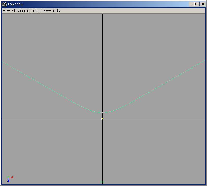
8 Linear NURB curve in green. Control vertices in yellow.

9 Cubic NURB curve in green. Control vertices in yellow. Hull in brown.

10 Control Vertices v. Edit Points Control Vertices (CVs): Define the region through which the curve passes. Do not usually lie on the curve itself (except for linear curves). Modifying a CV affects only a local region of the curve. Edit Points (EPs): Lie on the curve itself. Correspond to specific values of u-parameter. Modifying an EP can affect the entire curve. Curves can be created by specifying CVs or EPs.
: Lie on the curve itself.")
11 NURB curve created by specifying 5 control vertices.

12 NURB curve created by specifying the same 5 points as edit points.

13 A NURB curve can be edited by directly moving CVs. First press the Select by Component Type Button. Then select a (purple) CV. The white line indicates the parts of the curve that are affected when the CV is moved.

14 CVs, Spans and Degree General Polynomial Curves: Degree + Number of Spans = Number of CVs Cubic Polynomial Curves: 3 + Number of Spans = Number of CVs Every curve has at least one span. Therefore a cubic curve has at least 4 CVs.

15 Rebuilding a NURB Curve Increase Number of Spans. Increases number of CVs defining curve. Curve shape remains unchanged. (Depending on options selected.) User has finer control over curve shape. Decrease Number of Spans. Decreases number of CVs defining curve. Curve usually changes shape. User has grosser control over curve shape.

16 Original curve with 2 spans.

17 Modified curve with 2 spans.

18 Original curve with 8 spans.

19 Modified curve with 8 spans.

20 Pick Walking Go into component selection mode. Select a control vertex (CV). Use Right/Left or Up/Down arrow keys. Move forward/back along CV sequence.

21 EditCurves-CurveEditingTool Parameter Handle: Change the u-parameter of the point you are editing. Position Handle: Change the world space location of the point you are editing. Tangent Direction Handle: Change the direction of the curve at the point you are editing. Tangent Scale Handle: Control how fast the tangent changes as it passes through the point you are editing.
22 Tangent Direction Handle Tangent Scale Handle Axis Snap Lines Parameter Handle Position Handle
23 Open, Closed and Periodic Curves An open curve may have its start and end edit points in different locations. The start and end edit points may be moved independently. A closed curve has its start and end edit points at the same location, called the seam. If you move the start point, the end point moves with it (and visa versa). A periodic is similar to a closed curve, but it has two unseen spans at the end of the curve that overlap the first two spans. The unseen spans help maintain continuity along the seam.
24 Non-smooth open curve with coinciding start and end points.

25 Do EditCurves-Open/CloseCurves to make it periodic.
26 Select an edit or curve point and do EditCurves-DetachCurves to make it closed. The new start and end points may now be moved independently.
27 Attaching Curves Select two curves: Curve1 and Curve2. Use Menu Command: EditCurves-Attach-[]. Connect option generates a new curve that is continuous, but usually not smooth. The end of Curve2 is attached to the start of Curve2. (If necessary, Curve2 is modified.) Blend option generates a new curve that is continuous and smooth. The end of Curve2 is attached to the start of Curve2. (If necessary, both Curve1 and Curve2 are modified. The Bias setting determines which curve gets modified more, and which gets modified less.)
28 Attaching two curves using the Connect option.

29 Attaching two curves using the Blend option. (Bias=0.5)
30 If we attach these two curves, which combination of ends will be joined?
31 If we use Select by Component Type to go into Component Mode, we see a small u near the start of each curve.

32 We select the lower curve and do EditCurves-ReverseCurveDirection, and go into Component Mode. Now the lower curve now starts at other end.
33 Parametric Surface A procedure for distorting a planar square into a (possibly) curved surface. The procedure lives in a black box: The box takes a number u from 0 to 1 on one input wire. The box takes a number v from 0 to 1 on another input wire. The box puts a point in a 3D world on its output wire. The procedure defines a mathematical function s(u,v) that maps the 2D unit square into the 3D space R 3.
34 Parametric Surface 1 v s s s s 0 1 u
![We create a NURB surface using Create-NURBSPrimitives-Plane-[] and select 4 spans](/docs-images/24/2595960/images/35-0.png "(patches) in the U direction and 4 spans (patches) in the V direction.")
 is shown on left.")
35 We create a NURB surface using Create-NURBSPrimitives-Plane-[] and select 4 spans (patches) in the U direction and 4 spans (patches) in the V direction. Then we go into Component mode and select the 9 central CVs and move them upward. The result in Component Mode (wire frame) is shown on left. Object Mode (smooth shaded) is shown on right.
36 Notice that we have 7 CVs in the U (horizontal) direction and 7 CVs in the V (vertical direction). Try going into Component Mode and selecting a CV. Then use the arrow keys to move right/left along a row or up/down along a column.
37 Isoparms An isoparm is a curve that lies in a NURB surface. They come in two varieties: Curve of constant u (varying v) value. Curve of constant v (varying u) value. Use the RMB marking menu to go into Isoparm mode, and then use LMB and drag to select an isoparm.
38 Constant v isoparm shown in yellow.
39 Constant u isoparm shown in yellow.
40 Isoparms define a local coordinate system at each point on the surface. You can see this if you go into Component Mode, select a CV, double click the Move tool and choose Normal coordinates. Now you can move CVs in the U, V or N direction.

41 A NURB surface can be edited by directly moving CVs. The white lines indicate the parts of the surface that are affected by the selected CV.
42 EditNurbs-SurfaceEditing-SurfaceEditingTool Parameter Handle: Change the u and v parameters of the point you are editing. Position Handle: Change the world space location of the point you are editing. Toggle Button: Cycles through editing u tangent, v tangent and surface normal. Tangent / Normal Direction Handle: Change the direction of the tangent or surface normal at the point you are editing. Tangent Scale Handle: Control how fast the tangent changes as it passes through the point you are editing.
43 Tangent / Normal Direction Handle Tangent Scale Handle Axis Snap Lines Toggle Button Parameter Handle Position Handle
44 Constructing Surfaces from Curves Loft: Straight line isoparms. Revolve: Circular isoparms Extrude: Arbitrary fixed isoparms. Birail: Arbitrary varying isoparms.
45 Create two NURB curves. Select both of them. Apply the Surfaces-Loft tool.
46 All u-constant isoparms are straight lines. Nearest v=0 isoparm is one NURB curve. Farthest v=1 isoparm is the other NURB curve. The v-constant isoparms are blends of the two NURB curves.
47 Lofting Questions Question: How does Maya decide where to put the linear isoparms? Answer: Equally spaced points connect equally spaced points. Question: Yes, but how does Maya know which ends of the curves are matched with each other? Answer: The point u=0 on one curve matches with the point u=0 on the other curve. Likewise for u=1 points. You can test this by reversing the direction of one of the curves.
48 Create one NURB curve to serve as a profile. Apply the Surfaces-Revolve tool.
49 All u-constant isoparms are circles. All v-constant isoparms are rotated copies of the profile curve.
50 Create two NURB curves. Apply the (flat) Surfaces-Extrude tool.
51 All u-constant isoparms are translated copies of one curve. All v-constant isoparms are translated copies of the other curve.
52 Flat v. Tube Extrusion Flat maintains the orientation of the cross section as it moves along the extrusion path. Tube sweeps the cross section along the path with the reference vector staying tangent to the path.
53 Extruding Questions Question: If the curves are not connected at their u=0 points, which curve gets moved? Answer: The curve you selected first stays put. The curve you selected second gets moved.
54 Create one NURB curve to serve as a profile. Create two NURB curves to serve as rails. Select the profile and then select the two rails. Apply the Surfaces-Birail-1 tool.
55 All u-constant isoparms are translated, rotated and scaled copies of the profile curve. The v=0 and v=1 isoparms are the rail curves. The v-constant isoparms are blends of the two rail curves.
56 Editing and Animating History Suppose we create surface S from curves C1 and C2 using Loft, Revolve, Extrude, etc. Suppose also that we maintain the creation history for surface S. Later we can edit C1 and/or C2 and S will be automatically updated. Also, we can animate C1 and/or C2 and S will respond appropriately during the animation.
57 Exercise: Model & Animate a Leaf Go into Top view and turn on Grid Snapping. Make two curves that meet at u=0. One curve should be on the Z axis, starting at the origin. (RailA1) One curve should start at the origin and branch away from the first. (RailB1) Make a curve that connects the separated ends of the rail curves. (Profile1) Select Profile1 and then select RailA1 and RailB1. Invoke Surfaces-Birail-Biral1Tool. Invoke Edit-DuplicateSpecial-[] and click Duplicate Input Graph and confirm. Select RailA2, RailB2 and Profile2. Go to the channel box and enter -1 into the ScaleX channel. Select both surfaces and invoke EditNURBs-AttachSurfaces. Move any profile or rail curve and see how the leaf responds.
58 demo-04-birail-attach-leaf.mb
59 Modeling a Human Head with NURBS Start with a sphere. Place the a pole in one of several places: Poles at crown and neck. Poles at mouth and crown. Poles at mouth and neck. One pole at each ear. Advantages and disadvantages of each.
60 George Maestri Pole at crown offers good control over brow and nose, but causes problems where isoparms come together at edge of mouth. demo-04-head-crown-neck-pole-maestri.mb
61 George Maestri Pole at mouth offers good control of mouth and lips, but causes problems in the eye sockets since iosparms are sparse there. demo-04-head-mouth-crown-pole-maestri.mb
62 George Maestri Poles at ears is good for ears and eye sockets, but causes problems where isoparms come together at edge of mouth. demo-04-head-ear-ear-pole-maestri.mb
63 demo-04-head-mouth-neck-pole-ellman.mb NURB head with poles at mouth and neck by Ellman following Maraffi s instructions.
64 Design by Stepwise Refinement 1. Begin with a curve or surface with few CVs. 2. Move CVs to get a rough approximation of the desired surface. 3. Repeat: a. Add rows or columns of CVs in selected locations. b. Move new (or old) CVs to add detail to surface.
65 Start with one span (four rows/columns) in each direction.
![Invoke EditNURBS-InsertIsoparms[]. Press and hold RMB to invoke the marking menu and select Isoparms.](/docs-images/24/2595960/images/66-0.png "Then use LMB to select an isoparm on the surface and confirm the dialog box. Maya will add a row or column of CVs, depending on the direction of isoparm you selected.")
66 Invoke EditNURBS-InsertIsoparms[]. Press and hold RMB to invoke the marking menu and select Isoparms. Then use LMB to select an isoparm on the surface and confirm the dialog box. Maya will add a row or column of CVs, depending on the direction of isoparm you selected. Here we see the result of successively adding a U isoparm and a V isoparm.
67 Here we see the result of adding yet another U isoparm and another V isoparm. Now we have finer control near the added isoparms, especially where they cross.
68 Problem with Refining NURBs Each time we want more detail, we must do one of two things: Add a whole row of CVs. Add a whole column of CVs. But we really only care about the area where the row and column cross. Solution: Use multiple NURB patches.
69 EditNURBS-AttachSurfaces[] Create one single NURB surface out of two existing NURB surfaces. May involve moving and/or modifying surfaces so that joined edges coincide. May involve adding rows or columns of CVs to one surface so surfaces have same number of spans along edges being joined. Connect: Allow tangent to be discontinuous along the curve where the surfaces are attached. Blend: Modify one or both surfaces so that tangent is continuous along the line where the surfaces are attached.
70 Two NURB surfaces selected. One has more rows and columns of CVs than the other.
71 Connect Attachment: First one surface was rebuilt to have as many CV columns as the other surface. Then the two surfaces became one surface.
72 Blend Attachment: One surface was rebuilt. Both surfaces were modified to make the tangent continuous across the join curve.
73 EditNurbs-Stitch Impose a continuity or smoothness constraint on two surfaces. Do not create a single, combined surfaces. Allow the two surfaces to retain their separate identities. In particular, the two surfaces may have different numbers of rows and columns of CVs.
74 Two surfaces with differing topologies about to be stitched together.
75 Surfaces still have different topologies after stitching to enforce position and tangent continuity.

76 Surfaces remain continuous and smooth at the boundary, even as one of them is moved.
77 Creating a Multi-Patch Head Create a single-surface NURBs head. Make the surface live. Draw concentric curves for eyelids and loft them together. Draw concentric curves for ears and loft them together. Detach NURBs surface into patches. Stitch eyelid and ear patches together with select patches from the original NURBs surface.
78 demo-04-head-patch-choi.mb Multi-Patch NURB Head by Jae-Jin Choi
79 demo-04-head-patch-beardsly.mb Multi-Patch NURB Head by Beardsly
80 demo-04-head-patch-fischthal.mb Multi-Patch NURB Head by Mike Fischthal VC 05
81 Additional Topics Curve and surface fillets. Boolean combinations of surfaces. Trimmed surfaces. Artisan sculpting tool.
82 Challenge Problems Wine Glass. Teapot. Coiled Spring. Pretzel. Blade of Grass. Field of Grass. Cactus. Flower. Ear. Hand. Sponge. Brick wall. Pile of bricks. Car Body. House. City Skyline.
Computer Graphics. Geometric Modeling. Page 1. Copyright Gotsman, Elber, Barequet, Karni, Sheffer Computer Science - Technion. An Example.
 An Example 2 3 4 Outline Objective: Develop methods and algorithms to mathematically model shape of real world objects Categories: Wire-Frame Representation Object is represented as as a set of points
We can display an object on a monitor screen in three different computer-model forms: Wireframe model Surface Model Solid model
 CHAPTER 4 CURVES 4.1 Introduction In order to understand the significance of curves, we should look into the types of model representations that are used in geometric modeling. Curves play a very significant
1 CHORD LENGTH OR UNIFORM PARAMETERIZATION
 1 CHORD LENGTH OR UNIFORM PARAMETERIZATION All of the better high end packages that implement Nurbs Modeling tools will offer the choice of constructing curves using either Uniform or Chord Length parameterization.
Computer Graphics CS 543 Lecture 12 (Part 1) Curves. Prof Emmanuel Agu. Computer Science Dept. Worcester Polytechnic Institute (WPI)
 Curves. Prof Emmanuel Agu. Computer Science Dept. Worcester Polytechnic Institute (WPI)") Computer Graphics CS 54 Lecture 1 (Part 1) Curves Prof Emmanuel Agu Computer Science Dept. Worcester Polytechnic Institute (WPI) So Far Dealt with straight lines and flat surfaces Real world objects include
Computer Graphics CS 54 Lecture 1 (Part 1) Curves Prof Emmanuel Agu Computer Science Dept. Worcester Polytechnic Institute (WPI) So Far Dealt with straight lines and flat surfaces Real world objects include
Advanced Surface Modeling
 This sample chapter is for review purposes only. Copyright The Goodheart-Willcox Co., Inc. ll rights reserved. Chapter dvanced Modeling Learning Objectives fter completing this chapter, you will be able
Understand the Sketcher workbench of CATIA V5.
 Chapter 1 Drawing Sketches in Learning Objectives the Sketcher Workbench-I After completing this chapter you will be able to: Understand the Sketcher workbench of CATIA V5. Start a new file in the Part
Geometric Modelling & Curves
 Geometric Modelling & Curves Geometric Modeling Creating symbolic models of the physical world has long been a goal of mathematicians, scientists, engineers, etc. Recently technology has advanced sufficiently
the points are called control points approximating curve
 Chapter 4 Spline Curves A spline curve is a mathematical representation for which it is easy to build an interface that will allow a user to design and control the shape of complex curves and surfaces.
(Refer Slide Time: 1:42)
") Introduction to Computer Graphics Dr. Prem Kalra Department of Computer Science and Engineering Indian Institute of Technology, Delhi Lecture - 10 Curves So today we are going to have a new topic. So far
Introduction to Computer Graphics Dr. Prem Kalra Department of Computer Science and Engineering Indian Institute of Technology, Delhi Lecture - 10 Curves So today we are going to have a new topic. So far
SpaceClaim Introduction Training Session. A SpaceClaim Support Document
 SpaceClaim Introduction Training Session A SpaceClaim Support Document In this class we will walk through the basic tools used to create and modify models in SpaceClaim. Introduction We will focus on:
CATIA Wireframe & Surfaces TABLE OF CONTENTS
 TABLE OF CONTENTS Introduction... 1 Wireframe & Surfaces... 2 Pull Down Menus... 3 Edit... 3 Insert... 4 Tools... 6 Generative Shape Design Workbench... 7 Bottom Toolbar... 9 Tools... 9 Analysis... 10
Blender 3D Animation
 Bachelor Maths/Physics/Computer Science University Paris-Sud Digital Imaging Course Blender 3D Animation Christian Jacquemin Introduction to Computer Animation Animation Basics animation consists in changing
Curves and Surfaces. Goals. How do we draw surfaces? How do we specify a surface? How do we approximate a surface?
 Curves and Surfaces Parametric Representations Cubic Polynomial Forms Hermite Curves Bezier Curves and Surfaces [Angel 10.1-10.6] Goals How do we draw surfaces? Approximate with polygons Draw polygons
Wireframe and Surface
 Wireframe and Surface Preface What's New Getting Started Basic Tasks Workbench Description Glossary Index Dassault Systèmes 1994-99. All rights reserved. Preface CATIA Version 5 Wireframe and Surface allows
2013 Getting Started Guide
 2013 Getting Started Guide The contents of this guide and accompanying exercises were originally created by Nemetschek Vectorworks, Inc. Vectorworks Fundamentals Getting Started Guide Created using: Vectorworks
Basic controls of Rhinoceros 3D software
 lecture 2 Basic controls of Rhinoceros 3D software After the start Rhinoceros 3D software shows basic working area compound by four viewports (show model in other positions), popup menu over, palette menu
Modeling Tools Objectives. Sweeps and Lofts. Loft Feature
 Modeling Tools Objectives When you complete this module, you will be able to recognize the more advanced modeling tools in Solid Edge as well as the tools that require more input than typical Solid Edge
CSE 167: Lecture 13: Bézier Curves. Jürgen P. Schulze, Ph.D. University of California, San Diego Fall Quarter 2011
 CSE 167: Introduction to Computer Graphics Lecture 13: Bézier Curves Jürgen P. Schulze, Ph.D. University of California, San Diego Fall Quarter 2011 Announcements Homework project #6 due Friday, Nov 18
Introduction to CATIA V5
 Introduction to CATIA V5 Release 16 (A Hands-On Tutorial Approach) Kirstie Plantenberg University of Detroit Mercy SDC PUBLICATIONS Schroff Development Corporation www.schroff.com www.schroff-europe.com
Generative Shape Design
 Generative Shape Design Preface What's New Getting Started Basic Tasks Advanced Tasks Workbench Description Glossary Index Dassault Systèmes 1994-99. All rights reserved. Preface CATIA Version 5 Generative
Essential Mathematics for Computer Graphics fast
 John Vince Essential Mathematics for Computer Graphics fast Springer Contents 1. MATHEMATICS 1 Is mathematics difficult? 3 Who should read this book? 4 Aims and objectives of this book 4 Assumptions made
How To Use Design Mentor
 DesignMentor: A Pedagogical Tool for Computer Graphics and Computer Aided Design John L. Lowther and Ching Kuang Shene Programmers: Yuan Zhao and Yan Zhou (ver 1) Budirijanto Purnomo (ver 2) Michigan Technological
Tutorial: 2D Pipe Junction Using Hexa Meshing
 Tutorial: 2D Pipe Junction Using Hexa Meshing Introduction In this tutorial, you will generate a mesh for a two-dimensional pipe junction, composed of two inlets and one outlet. After generating an initial
IT 386: 3D Modeling and Animation. Review Sheet. Notes from Professor Nersesian s IT 386: 3D Modeling and Animation course
 IT 386: 3D Modeling and Animation Review Sheet Sources: Notes from Professor Nersesian s IT 386: 3D Modeling and Animation course Notes from CannedMushrooms on YouTube Notes from Digital Tutors tutorial
After completing this tutorial, you will be able to: Use the new 3D Modeling tools in AutoCAD 2007 for basic Lofting.
 TUTORIAL 3 Lofted Solid Learning Objectives After completing this tutorial, you will be able to: Use the new 3D Modeling tools in AutoCAD 2007 for basic Lofting. Required Competencies Before starting this
Maya 2014 Basic Animation & The Graph Editor
 Maya 2014 Basic Animation & The Graph Editor When you set a Keyframe (or Key), you assign a value to an object s attribute (for example, translate, rotate, scale, color) at a specific time. Most animation
10.0-2. Finite Element Modeling
 What s New in FEMAP FEMAP 10.0 and 10.0.1 include enhancements and new features in: User Interface on page 3 Meshing on page 23 Mesh Associativity on page 33 Properties on page 33 Functions on page 35
Modeling Curves and Surfaces
 Modeling Curves and Surfaces Graphics I Modeling for Computer Graphics!? 1 How can we generate this kind of objects? Umm!? Mathematical Modeling! S Do not worry too much about your difficulties in mathematics,
Classroom Tips and Techniques: The Student Precalculus Package - Commands and Tutors. Content of the Precalculus Subpackage
 Classroom Tips and Techniques: The Student Precalculus Package - Commands and Tutors Robert J. Lopez Emeritus Professor of Mathematics and Maple Fellow Maplesoft This article provides a systematic exposition
Datum > Curve KIM,ME,NIU
 Datum > Curve Intersect First create at least one quilt on the surface of the model. Feature > Surface (> New) > Copy (do not use offset that creates a surface off the solid surface even with zero offset)
Tutorial: 3D Pipe Junction Using Hexa Meshing
 Tutorial: 3D Pipe Junction Using Hexa Meshing Introduction In this tutorial, you will generate a mesh for a three-dimensional pipe junction. After checking the quality of the first mesh, you will create
Chapter 1. Creating Sketches in. the Sketch Mode-I. Evaluation chapter. Logon to www.cadcim.com for more details. Learning Objectives
 Chapter 1 Creating Sketches in Learning Objectives the Sketch Mode-I After completing this chapter you will be able to: Use various tools to create a geometry. Dimension a sketch. Apply constraints to
An introduction to 3D draughting & solid modelling using AutoCAD
 An introduction to 3D draughting & solid modelling using AutoCAD Faculty of Technology University of Plymouth Drake Circus Plymouth PL4 8AA These notes are to be used in conjunction with the AutoCAD software
SolidWorks Implementation Guides. Sketching Concepts
 SolidWorks Implementation Guides Sketching Concepts Sketching in SolidWorks is the basis for creating features. Features are the basis for creating parts, which can be put together into assemblies. Sketch
Castle Modeling. In this PDF tutorial we will be modeling a simple castle as pictured above.
 Course: 3D Design Title: Castle Modeling Blender: Version 2.6X Level: Beginning Author; Neal Hirsig ([email protected]) May, 2012 This tutorial assumes that you already know how to: Display orthographic
CHAPTER 1 Splines and B-splines an Introduction
 CHAPTER 1 Splines and B-splines an Introduction In this first chapter, we consider the following fundamental problem: Given a set of points in the plane, determine a smooth curve that approximates the
Autodesk Fusion 360 Badge Guide: Design an F1 in Schools Trophy
 Autodesk Fusion 360 Badge Guide: Design an F1 in Schools Trophy Abstract: Gain basic understanding of creating 3D models in Fusion 360 by designing an F1 in Schools trophy. This badge may be claimed by
511 - Creating Structural Frame Designs
 4 th Generation VLC courtesy of Edison2 511 - Creating Structural Frame Designs Rahul Kulkarni, Manager, Product Design, Pune Center, Siemens PLM Software #SEU13 Agenda: 511 - Creating Structural Frame
HowTo Rhino & ICEM. 1) New file setup: choose Millimeter (automatically converts to Meters if imported to ICEM)
 New file setup: choose Millimeter (automatically converts to Meters if imported to ICEM)") HowTo Rhino & ICEM Simple 2D model 1) New file setup: choose Millimeter (automatically converts to Meters if imported to ICEM) 2) Set units: File Properties Units: Model units: should already be Millimeters
HowTo Rhino & ICEM Simple 2D model 1) New file setup: choose Millimeter (automatically converts to Meters if imported to ICEM) 2) Set units: File Properties Units: Model units: should already be Millimeters
Pro/ENGINEER Wildfire 4.0 Basic Design
 Introduction Datum features are non-solid features used during the construction of other features. The most common datum features include planes, axes, coordinate systems, and curves. Datum features do
SolidWorks: Mirror, Revolve, and. Introduction to Robotics
 SolidWorks: Mirror, Revolve, and Circular Pattern Introduction to Robotics Let s Review At this point we have learned the following: Extrude Boss/Base Extruded Cut Adding Relations and Dimensions Linear
Figure 2.1: Center of mass of four points.
 Chapter 2 Bézier curves are named after their inventor, Dr. Pierre Bézier. Bézier was an engineer with the Renault car company and set out in the early 196 s to develop a curve formulation which would
Intermediate Tutorials Modeling - Trees. 3d studio max. 3d studio max. Tree Modeling. 1.2206 2006 Matthew D'Onofrio Page 1 of 12
 3d studio max Tree Modeling Techniques and Principles 1.2206 2006 Matthew D'Onofrio Page 1 of 12 Modeling Trees Tree Modeling Techniques and Principles The era of sprites and cylinders-for-trunks has passed
SOLIDWORKS: SKETCH RELATIONS
 Sketch Feature: The shape or topology of the initial sketch or model is important, but exact geometry and dimensions of the initial sketched shapes are NOT. It recommended to work in the following order:
Content. Chapter 4 Functions 61 4.1 Basic concepts on real functions 62. Credits 11
 Content Credits 11 Chapter 1 Arithmetic Refresher 13 1.1 Algebra 14 Real Numbers 14 Real Polynomials 19 1.2 Equations in one variable 21 Linear Equations 21 Quadratic Equations 22 1.3 Exercises 28 Chapter
ART 269 3D Animation Fundamental Animation Principles and Procedures in Cinema 4D
 ART 269 3D Animation Fundamental Animation Principles and Procedures in Cinema 4D Components Tracks An animation track is a recording of a particular type of animation; for example, rotation. Some tracks
Chapter 9. Editing Features. Learning Objectives
 Chapter 9 Editing Features Learning Objectives After completing this chapter, you will be able to: Edit features. Edit sketches of the sketch based features. Edit the sketch plane of the sketch based features.
Generative Shape Optimizer
 CATIA V5 Training Foils Generative Shape Optimizer Version 5 Release 19 January 2009 EDU_CAT_EN_GSO_FI_V5R19 1 About this course Objectives of the course Upon completion of the course you will learn to:
Autodesk Fusion 360: Assemblies. Overview
 Overview In this module you will learn how different components can be put together to create an assembly. We will use several tools in Fusion 360 to make sure that these assemblies are constrained appropriately
Glass coloured glass may pick up on scan. Top right of screen tabs: these tabs will relocate lost windows.
 Artec 3D scanner Instructions for Medium Handheld (MH) Scanner Scanning Conditions: Objects/surfaces that don t scan well: Black or shiny objects and objects with sharp edges or points, hair, glass, transparent
CATIA V5 Tutorials. Mechanism Design & Animation. Release 18. Nader G. Zamani. University of Windsor. Jonathan M. Weaver. University of Detroit Mercy
 CATIA V5 Tutorials Mechanism Design & Animation Release 18 Nader G. Zamani University of Windsor Jonathan M. Weaver University of Detroit Mercy SDC PUBLICATIONS Schroff Development Corporation www.schroff.com
 Edinburgh COLLEGE of ART ARCHITECTURE 3D Modelling in AutoCAD - tutorial exercise The screen The graphics area This is the part of the screen in which the drawing will be created. The command prompt area
TABLE OF CONTENTS. INTRODUCTION... 5 Advance Concrete... 5 Where to find information?... 6 INSTALLATION... 7 STARTING ADVANCE CONCRETE...
 Starting Guide TABLE OF CONTENTS INTRODUCTION... 5 Advance Concrete... 5 Where to find information?... 6 INSTALLATION... 7 STARTING ADVANCE CONCRETE... 7 ADVANCE CONCRETE USER INTERFACE... 7 Other important
CATIA Basic Concepts TABLE OF CONTENTS
 TABLE OF CONTENTS Introduction...1 Manual Format...2 Log on/off procedures for Windows...3 To log on...3 To logoff...7 Assembly Design Screen...8 Part Design Screen...9 Pull-down Menus...10 Start...10
QUICK REFERENCE: ADOBE ILLUSTRATOR CS2 AND CS3 SECTION 1: CS3 TOOL BOX: PAGE 2 SECTION 2: CS2 TOOL BOX: PAGE 11
 QUICK REFERENCE, ADOBE ILLUSTRATOR, PAGE 1 QUICK REFERENCE: ADOBE ILLUSTRATOR CS2 AND CS3 CS2 SECTION 1: CS3 TOOL BOX: PAGE 2 SECTION 2: CS2 TOOL BOX: PAGE 11 SECTION 3: GENERAL CONCEPTS: PAGE 14 SELECTING
Part Design. Preface What's New? Getting Started Basic Tasks Advanced Tasks Workbench Description Customizing Glossary Index
 Part Design Preface What's New? Getting Started Basic Tasks Advanced Tasks Workbench Description Customizing Glossary Index Dassault Systèmes 1994-99. All rights reserved. Preface The CATIA Version 5 Part
CS 4620 Practicum Programming Assignment 6 Animation
 CS 4620 Practicum Programming Assignment 6 Animation out: Friday 14th November 2014 due: : Monday 24th November 2014 1 Introduction In this assignment, we will explore a common topic in animation: key
MassArt Studio Foundation: Visual Language Digital Media Cookbook, Fall 2013
 INPUT OUTPUT 08 / IMAGE QUALITY & VIEWING In this section we will cover common image file formats you are likely to come across and examine image quality in terms of resolution and bit depth. We will cover
Quick Start Tutorial Imperial version
 Quick Start Tutorial Imperial version 1996-2006 Cadsoft Corporation. No part of this guide or the accompanying software may be reproduced or transmitted, electronically or mechanically, without written
1. Abstract 2. Introduction 3. Algorithms and Techniques
 MS PROJECT Virtual Surgery Piyush Soni under the guidance of Dr. Jarek Rossignac, Brian Whited Georgia Institute of Technology, Graphics, Visualization and Usability Center Atlanta, GA [email protected],
SAP2000 Getting Started Tutorial
 SAP2000 Getting Started Tutorial Learn how to define materials, sections, grids, and supports with basic modeling concepts for creating and modifying a concrete bent structure model using a nonprismatic
Excel -- Creating Charts
 Excel -- Creating Charts The saying goes, A picture is worth a thousand words, and so true. Professional looking charts give visual enhancement to your statistics, fiscal reports or presentation. Excel
BEZIER CURVES AND SURFACES
 Department of Applied Mathematics and Computational Sciences University of Cantabria UC-CAGD Group COMPUTER-AIDED GEOMETRIC DESIGN AND COMPUTER GRAPHICS: BEZIER CURVES AND SURFACES Andrés Iglesias e-mail:
Raising the Roof Creating Roofs in Revit David Cohn
 David Cohn AB322-1 Roofs are one of the most complex architectural elements to model, but with Revit you can create just about any type of roof. This class will explore the best methods for creating various
Intro to 3D Animation Using Blender
 Intro to 3D Animation Using Blender Class Instructor: Anthony Weathersby Class Objectives A primer in the areas of 3D modeling and materials An introduction to Blender and Blender s toolset Course Introduction
Working With Animation: Introduction to Flash
 Working With Animation: Introduction to Flash With Adobe Flash, you can create artwork and animations that add motion and visual interest to your Web pages. Flash movies can be interactive users can click
Creating Your Own 3D Models
 14 Creating Your Own 3D Models DAZ 3D has an extensive growing library of 3D models, but there are times that you may not find what you want or you may just want to create your own model. In either case
Computer Animation: Art, Science and Criticism
 Computer Animation: Art, Science and Criticism Tom Ellman Harry Roseman Lecture 12 Ambient Light Emits two types of light: Directional light, coming from a single point Contributes to diffuse shading.
Introduction to Autodesk Inventor for F1 in Schools
 F1 in Schools race car Introduction to Autodesk Inventor for F1 in Schools In this course you will be introduced to Autodesk Inventor, which is the centerpiece of Autodesk s Digital Prototyping strategy
Course: 3D Design Title: Deciduous Trees Blender: Version 2.6X Level: Beginning Author; Neal Hirsig ([email protected]) (June 2012) Deciduous Trees
 (June 2012) Deciduous Trees") Course: 3D Design Title: Deciduous Trees Blender: Version 2.6X Level: Beginning Author; Neal Hirsig ([email protected]) (June 2012) Deciduous Trees In general, modeling trees is a long and somewhat tedious
Course: 3D Design Title: Deciduous Trees Blender: Version 2.6X Level: Beginning Author; Neal Hirsig ([email protected]) (June 2012) Deciduous Trees In general, modeling trees is a long and somewhat tedious
Lession: 2 Animation Tool: Synfig Card or Page based Icon and Event based Time based Pencil: Synfig Studio: Getting Started: Toolbox Canvas Panels
 Lession: 2 Animation Tool: Synfig In previous chapter we learn Multimedia and basic building block of multimedia. To create a multimedia presentation using these building blocks we need application programs
H.Calculating Normal Vectors
 Appendix H H.Calculating Normal Vectors This appendix describes how to calculate normal vectors for surfaces. You need to define normals to use the OpenGL lighting facility, which is described in Chapter
Twelve. Figure 12.1: 3D Curved MPR Viewer Window
 Twelve The 3D Curved MPR Viewer This Chapter describes how to visualize and reformat a 3D dataset in a Curved MPR plane: Curved Planar Reformation (CPR). The 3D Curved MPR Viewer is a window opened from
Introduction to Autodesk Inventor for F1 in Schools
 Introduction to Autodesk Inventor for F1 in Schools F1 in Schools Race Car In this course you will be introduced to Autodesk Inventor, which is the centerpiece of Autodesk s digital prototyping strategy
Pro/ENGINEER Wildfire 5.0 Introduction to Surface Modeling
 Introduction Several advanced surface types are available as listed below. Variable Section Sweep Boundary Blend Section to Surfaces Blend Surface to Surface Blend A surface is created by sweeping a single
NURBS Drawing Week 5, Lecture 10
 CS 430/536 Computer Graphics I NURBS Drawing Week 5, Lecture 10 David Breen, William Regli and Maxim Peysakhov Geometric and Intelligent Computing Laboratory Department of Computer Science Drexel University
A Novel Multitouch Interface for 3D Object Manipulation
 A Novel Multitouch Interface for 3D Object Manipulation Oscar Kin-Chung Au School of Creative Media City University of Hong Kong [email protected] Chiew-Lan Tai Department of Computer Science & Engineering
The Essentials of CAGD
 The Essentials of CAGD Chapter 2: Lines and Planes Gerald Farin & Dianne Hansford CRC Press, Taylor & Francis Group, An A K Peters Book www.farinhansford.com/books/essentials-cagd c 2000 Farin & Hansford
Solid Edge structural frames and weldments
 Solid Edge structural frames and weldments White Paper Intelligent, process-specific applications that speed time to manufacturing. White Paper Solid Edge structural frames and weldments 2 Contents Solid
GeoGebra. 10 lessons. Gerrit Stols
 GeoGebra in 10 lessons Gerrit Stols Acknowledgements GeoGebra is dynamic mathematics open source (free) software for learning and teaching mathematics in schools. It was developed by Markus Hohenwarter
Mastercam X6 Basic 3D Design
 Basic 3D Design mastercam x getting started tutorials Mastercam X6 Basic 3D Design December 2011 Be sure you have the latest information! Information might have been changed or added since this document
Communicate: In Print
 Communicate: In Print A simple guide Work areas Communicate: In Print has two different modes in which to edit your documents: Create and Adjust modes. These are easily interchangeable and the toolbars
Adobe Illustrator CS5 Part 1: Introduction to Illustrator
 CALIFORNIA STATE UNIVERSITY, LOS ANGELES INFORMATION TECHNOLOGY SERVICES Adobe Illustrator CS5 Part 1: Introduction to Illustrator Summer 2011, Version 1.0 Table of Contents Introduction...2 Downloading
CATIA for Design and Engineering. Version 5 Releases 14 & 15. David S. Kelley. Central Michigan University SDC
 CATIA for Design and Engineering ersion 5 Releases 4 & 5 David S. Kelley Central Michigan University SDC PUBLICATIONS Schroff Development Corporation www.schroff.com www.schroff-europe.com TUTORIAL Extruded
WORKBOOK MODELING OF MULTI- MEMBER MACHINES
 WORKBOOK MODELING OF MULTI- MEMBER MACHINES LUBLIN 2014 0 Author: Mirosław Ferdynus Desktop publishing: Mirosław Ferdynus Technical editor: Mirosław Ferdynus Figures: Mirosław Ferdynus Cover and graphic
How SolidWorks Speeds Consumer Product Design
 white paper How SolidWorks Speeds Consumer Product Design inspiration SUMMARY SolidWorks Premium bridges the gap between industrial design and engineering by providing powerful surfacing capabilities,
Plotting: Customizing the Graph
 Plotting: Customizing the Graph Data Plots: General Tips Making a Data Plot Active Within a graph layer, only one data plot can be active. A data plot must be set active before you can use the Data Selector
Bicycle Math. presented to the Olivetti Club. Timothy E. Goldberg. March 30, 2010. Cornell University Ithaca, New York
 Bicycle Math presented to the Olivetti Club Timothy E. Goldberg Cornell University Ithaca, New York March 30, 2010 Abstract Some pretty interesting mathematics, especially geometry, arises naturally from
B2.53-R3: COMPUTER GRAPHICS. NOTE: 1. There are TWO PARTS in this Module/Paper. PART ONE contains FOUR questions and PART TWO contains FIVE questions.
 B2.53-R3: COMPUTER GRAPHICS NOTE: 1. There are TWO PARTS in this Module/Paper. PART ONE contains FOUR questions and PART TWO contains FIVE questions. 2. PART ONE is to be answered in the TEAR-OFF ANSWER
NURBS Drawing Week 5, Lecture 10
 CS 430/536 Computer Graphics I NURBS Drawing Week 5, Lecture 10 David Breen, William Regli and Maxim Peysakhov Geometric and Intelligent Computing Laboratory Department of Computer Science Drexel University
Quick Start Tutorial Metric version
 Quick Start Tutorial Metric version 1996-2009 Cadsoft Corporation. No part of this guide or the accompanying software may be reproduced or transmitted, electronically or mechanically, without written permission
10. THERM DRAWING TIPS
 10. THERM DRAWING TIPS 10.1. Drawing Tips The THERM User's Manual describes in detail how to draw cross-sections in THERM. This section of the NFRC Simualation Training Manual presents some additional
Learning Autodesk. Modeling, Analysis and Animation SDC. Randy H. Shih. Better Textbooks. Lower Prices. PUBLICATIONS www.sdcpublications.
 Learning Autodesk Inventor 2012 Modeling, Analysis and Animation Randy H. Shih SDC Better Textbooks. Lower Prices. PUBLICATIONS www.sdcpublications.com Schroff Development Corporation Visit the following
VISUAL ALGEBRA FOR COLLEGE STUDENTS. Laurie J. Burton Western Oregon University
 VISUAL ALGEBRA FOR COLLEGE STUDENTS Laurie J. Burton Western Oregon University VISUAL ALGEBRA FOR COLLEGE STUDENTS TABLE OF CONTENTS Welcome and Introduction 1 Chapter 1: INTEGERS AND INTEGER OPERATIONS
This week. CENG 732 Computer Animation. Challenges in Human Modeling. Basic Arm Model
 CENG 732 Computer Animation Spring 2006-2007 Week 8 Modeling and Animating Articulated Figures: Modeling the Arm, Walking, Facial Animation This week Modeling the arm Different joint structures Walking
Figure 1 - Delta Theta Input Selection
 Creating Cams in Pro/Engineer Wildfire Using DYNACAM Mechanical Engineering Mechanical Design Created by: David E. Yamartino M.S. Mechanical Engineering May 2004 April 12, 2004 Objective: The objective