Lecture Note 31. Introduction to Steel-Concrete Composite Building
|
|
|
- Randall Hicks
- 9 years ago
- Views:
Transcription
1 160 Lecture Note 31 Introduction to Steel-Concrete Composite Building Code: IS : Code of Practice for Composite Construction in Structural Steel and Concrete Concept of Tall Building Design From a structural engineer's point of view tall building or multi-storeyed building is one that, by virtue of its height, is affected by lateral forces to an extent that they play an important role in the structural design Multi-storeyed buildings provide a large floor area in a relatively small area of land in urban centres. Advantages of Steel Tall Buildings Faster to erect Lighter Better quality control Reduced site time - Fast track Construction Large column free space and amenable for alteration Less material handling at site Less percentage of floor area occupied by structural elements Has better ductility and hence superior lateral load behavior; better earthquake resistance Anatomy Beams Columns Floors Bracing Systems Connections

2 161 Beam and Column Construction Beam One-way slab Column Common types of floor systems Concrete slabs supported by open-web joists One-way and two-way reinforced concrete slabs supported on steel beams Concrete slab and steel beam composite floors Composite profiled decking floors Precast concrete floors on steel beams Stud welding Concrete slab Tack weld Open web joist Bottom chord Concrete slabs supported by open-web joists

3 162 Welded wire mesh for effectively bonding fireproofing concrete. One-way and two-way reinforced concrete slabs supported on steel beams Steel beam encased in concrete (Rarely used nowadays) Steel beam acting composite with concrete slab using shear connectors Concrete slab and steel beam composite floors

4 163 Profiled decking floors Popular for lighter loads Advantages: Do not need form work Lightweight concrete is used resulting in reduced dead weight Decking distributes shrinkage strains, thus prevents serious cracking Decking stabilises the beam against lateral buckling, until the concrete hardens Cells in decking are convenient for locating services A Profiled sheet A Section A-A showing dimples Profiled decking floors Precast concrete slab floors

5 164 Lecture Note 32 Steel-concrete composite construction A composite member is defined as consisting of a rolled or a built-up structural steel shape that is either filled with concrete, encased by reinforced concrete or structurally connected to a reinforced concrete slab. Composite members are constructed such that the structural steel shape and the concrete act together to resist axial compression and /or bending. Advantages: Advantageous properties of both steel and concrete are effectively utilized in a composite structure. For a typical three (3) to ten (10) storied structure, time of construction of the complete structure reduces by about 25 percent. The advantages can be fully utilized as summarized below: 1. Faster construction for maximum utilization of rolled and/or fabricated components (structural steel members) and hence quick return of the invested capital.

6 Advantages based on life-cycle-cost analysis instead of initial cost only. 3. Quality assurance of the steel material along with availability of proper paint system suiting to different corrosive environment. 4. Ability to cover large column free area in buildings and longer span for bridges/flyovers. This leads to more usable space. 5. Reinforced cement concrete (RCC) slab is in compression and steel joist is in tension. Hence, most effective utilization of the materials can be achieved. 6. Better seismic resistance i.e. best suited to resist repeated earthquake loadings, which require a high amount of ductility and hysteretic energy of the material/structural frame. 7. Composite sections have higher stiffness than the corresponding steel sections (in a steel structure) and thus bending stress as well as deflection are lesser. 8. Keeping span and loading unaltered, a lower structural steel section (having lesser depth and weight) can be provided in composite construction, compared to the section required for non-composite construction. 9. Reduced beam depth reduces the story height and consequently the cost of cladding in a building and lowers the cost of embankment in a flyover (due to lower height of embankment). 10. Reduced depth allows provision of lower cost for fire proofing of beam s exposed faces. 11. Cost of formwork is lower compared to RCC construction. 12. Cost of handling and transportation is minimized for using major part of the structure fabricated in the workshop. 13. Easy structural repair/modification/maintenance. 14. Structural steel component has considerable scrap value at the end of useful life. 15. Reductions in overall weight of structure and thereby reduction in foundation costs. 16. More use of a material i.e. steel, which is durable, fully recyclable on replacement and environment friendly. Composite Beams: Slab and beam type constructions are commonly used in bridges and buildings. Slabbeam interaction is possible through the use of shear connector welded at the top of the flanges. This behaves like a T-beam with the slab or part of it acting as a flange in compression. Further, bond between the shear connector and slab is assumed to be perfect, i.e., no slippage between the top flange of the steel beam and slab is permitted. For determining section properties, it is convenient to transform the concrete slab into an
 slab is in compression and steel joist is in tension. Hence, most effective utilization of the materials can be achieved. 6. Better seismic resistance i.e. best suited to resist repeated earthquake loadings, which require a high amount of ductility and hysteretic energy of the material/structural frame.")
7 166 equivalent steel section by dividing concrete area by modular ratio. The rest of the analysis is carried out as if the section were made of a homogeneous material. In conventional composite construction, concrete slabs rest over steel beams and are supported by them. Under load these two components act independently and a relative slip occurs at the interface if there is no connection between them. With the help of a deliberate and appropriate connection provided between the beam and the concrete slab, the slip between them can be eliminated. In this case the steel beam and the slab act as a composite beam and their action is similar to that of a monolithic T- beam. Concrete is stronger in compression than in tension, and steel is susceptible to buckling in compression. By the composite action between the two, we can utilize their respective advantages to the fullest extent. Generally, in steel-concrete composite beams, steel beams are integrally connected to prefabricated or cast-in-situ reinforced concrete slabs. There are many advantages associated with steel concrete composite construction. Some of these are listed below. Advantages of Construction: The most effective utilization of steel and concrete is achieved. Keeping the span and loading unaltered, a more economical steel section (in terms of depth and weight) is adequate in composite construction compared with conventional non-composite construction. As the depth of beam reduces, the construction depth reduces, resulting in enhanced headroom. Because of its larger stiffness, composite beams have less deflection than steel beams. Composite construction is amenable to fast-tract construction because of using rolled steel and pre-fabricated components, rather than cast-in-situ concrete. Encased steel beam sections have improved fire resistance and corrosion. Disadvantages: 1. Additional costs for shear connectors and their installation. For lightly loaded short beams, this extra cost may exceed the cost-reduction on all accounts. Methods of Composite Construction of Beams Two methods of composite construction: Shored and Un-shored.

8 167 The concrete slab is usually cast after the steel beams are erected. The two methods of construction differ in the manner of supporting the formwork with fresh concrete and other construction loads. In shored method, the weight of formwork and fresh concrete is supported by a separate system of shores and steel beams carry their own weight only. When the concrete attains at least 75% of its 28-days strength, the shores are removed and then all loads including weight of concrete and live loads are carried by the composite action of steel and concrete. Thus in shored construction, as almost the entire load is carried by composite action, it is possible to use a lighter steel beam. In un-shored construction, no shores are used and the weight of the formwork, fresh concrete and steel beam and other construction loads are all carried by the steel beam alone. When the concrete attains at least 75% of its ultimate strength, the formwork is removed and all subsequent loads including the live loads are carried by the composite action. Thus in un- shored construction a relatively heavier steel beams is required. In shored method though there is some saving in steel, but there is extra cost of shoring. In practice, the ultimate economy in shored method is negligible or may be even negative. So it is preferable to use heavier steel beam and do away with shoring. The un-shored method is preferable for the following reasons: The trouble due to probable settlement of shoring is avoided in un-shored construction. The ultimate strength of composite beam with heavier steel section is higher. Thus with practically the same cost, higher safety margin is obtained in un-shored construction.

9 168 Lecture Note 33 Design of Composite Beam & Column Codal provisions of IS IS i.e. Code of Practice for Composite Construction in Structural Steel and Concrete is restricted to buildings only. It stipulates that the steel-concrete composite structures may be designed by the limit state method. As per IS , a composite structure or part of it, is considered, unfit for use when it exceeds the limit state, beyond which it infringes one of the criteria governing its performance or use. The limit states can be classified into the following categories: Ultimate Limite State which corresponds to the maximum load carrying capacity. Serviceability Limit State - which are related to the criteria governing normal use and durability. Ultimate Limit State to be considered in buildings and structures made of steel-concrete composite construction are: Collapse due to flexural failure of one or more critical sections, Collapse due to horizontal shear failure at the interface between the steel beam and the concrete slab, Collapse due to vertical separation of the concrete slab from the steel beam The serviceability limit states to be considered are as follows: Limit state of deflection, and Limit state of stresses in concrete and steel Design for the limit state of collapse in flexure is based on the following assumptions Plane sections normal to the axis remain plane-after bending. The maximum bending strain in concrete at the outermost compression fiber is taken as

10 169 For characteristic compressive strength of concrete f ck, maximum permissible bending compression in the structure is assumed to be 0.67 f ck. With a value of 1.5 for the partial safety factor for the strength of concrete material, maximum design stress is f ck. The tensile strength of concrete is ignored; The stress-strain curve for the steel section is assumed to be bilinear and partial safety factor of the material is Composite Columns: A steel-concrete composite column is a compression member, comprising either a concrete encased hot-rolled steel section or a concrete filled hollow section of hot-rolled steel. It is generally used as a load-bearing member in a composite framed structure. Figure 2: Typical cross-sections of fully or partially concrete encased composite columns.

11 170 Typical cross-sections of composite columns with fully concrete encased steel section and two partially concrete encased steel sections are illustrated in Figure1. Figure2 shows three typical cross-sections of concrete filled hollow sections. Note that there is no requirement to provide additional reinforcing steel for concrete filled hollow composite sections, except for requirements for fire resistance where appropriate. Mechanism of Load Resistance: In a composite column both the steel and the concrete sections would resist the external loading by interacting together by bond and friction. Supplementary reinforcement in the concrete encasement prevents excessive spalling of concrete both under normal load and fire conditions. Advantages of construction: With the use of composite columns along with composite decking and composite beams it is possible to erect high rise structures in an extremely efficient manner. There is quite a vertical spread of construction activity carried out simultaneously at any time, with numerous trades working simultaneously. For example One group of workers will be erecting the steel beams and columns for one or two storeys at the top of frame. Two or three storeys below, another group of workers will be fixing the metal decking for the floors. A few storeys below, another group will be concreting the floors. As we go down the building, another group is tying the column reinforcing bars in cages. Yet another group below them are fixing the formwork, placing the concrete into the column moulds etc. Advantages of composite columns: Increased strength for a given cross sectional dimensions. Increased stiffness, leading to reduced slenderness and increased buckling resistance. Good fire resistance Corrosion protection in encased columns. Significant economic advantages over either structural steel or reinforced concrete alternatives. Identical cross sections with different load and moment resistances can be produced by varying steel thickness, the concrete strength or reinforcement. This allows the

12 171 outer dimensions of a column to be held constant over a number of floors in a building, thus simplifying the construction and architectural detailing. Erection of high rise building in an extremely efficient manner. Formwork is not required for concrete filled tubular sections.

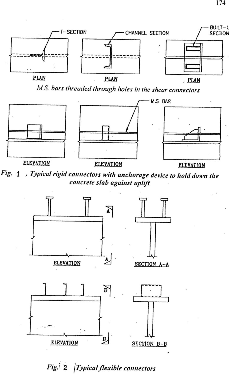
13 172 Lecture Note 34 Shear Connector Composite construction consists of providing monolithic action between prefabricated units like steel beams or pre-cast reinforced concrete or pre-stressed concrete beams and cast-in-situ concrete, so that the two will act as one unit. Although there is bound to be a certain amount of natural bond between concrete and steel at least at the initial stages, this bond cannot be relied upon as the same is likely to be deteriorate due to use and over load. Mechanical shear connectors are therefore provided to help the steel and concrete element to act in a composite manner ignoring the contribution made by the inherent natural bond towards this effect. Primarily shear connectors are intended to resist the horizontal movement between the concrete slab and the steel beam and to transmit the horizontal shear between the two. Shear Connectors are also called upon to prevent vertical separation of the slab from the steel girder at the contact surface. Therefore, shear connectors are to be designed to cater for integral action of the composite structure at all load conditions on the following basis: a) Transmission of longitudinal shear along the contact surface without slip. b) Prevention of vertical separation of the in-situ RC slab from the pre-fabricated structural beam. Types of Shear Connectors Shear connectors are generally classified into three categories, viz. a) Rigid type b) Flexible type c) Bond type The basic characteristic of the above connectors are discussed below: (a) Rigid Type Connectors: These connectors as the name implies, are designed to be bent proof with little inherent power of deformation. These types of shear connectors could be of various shapes, but the most common types are short length of bars, angles or tees welded on

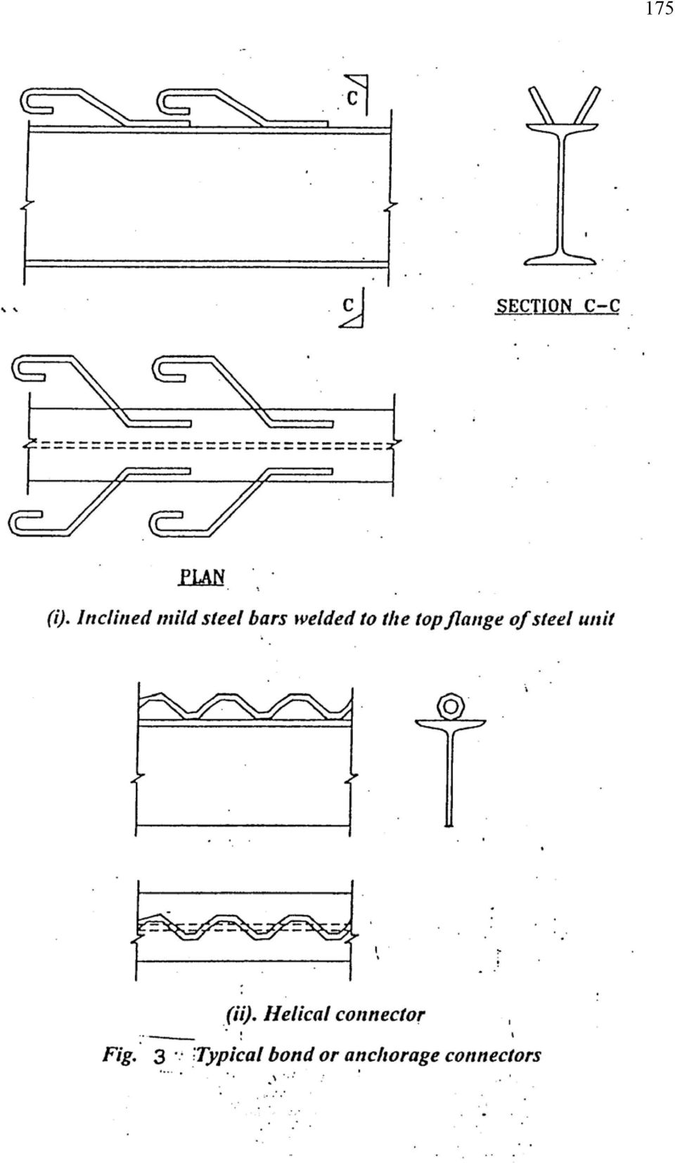
14 173 to the steel girder in manners shown in Figure 1. These connectors derive their resistance from bearing pressure of the concrete, distributed evenly over the surface because of the stiffness of the connectors. Failures in these types of connectors are generally associated with the crushing of concrete. It is customary to provide suitable anchorage device to these connectors to prevent in-situ concrete from being separated from the structural unit in the direction normal to the contact surface. The common method for this is to introduce longitudinal round bars through holes provided in the rigid connectors (Figure 1). (b) Flexible Type Connectors: Flexible type connectors such as studs, channels welded to the structural beams derive their resistance essentially through the bending of the connectors and normally failure occurs when the yield stress in the connector is exceeded resulting in slip between the structural beam and the concrete slab. Typical types of flexible connectors are illustrated in Figure 2. c) Bond or Anchorage Type Connectors: These connectors derive their resistance through bond and/or anchorage action. Typical bond type connectors have been illustrated in Figure 3. These normally consist of the following: Inclined bars with one end welded to the flange of the steel unit and the other suitably bent. M.S. bar welded to the flange of the steel unit in the form of helical stirrups.

15 174
16 175
17 176 Design Strength of Shear Connectors: Relevant codes: In India, primarily two codes of practices are in use for composite construction in structural steel and concrete. These are: I.R.C : Standard specifications and code of practice for road bridges, The Indian Road Congress, Delhi. I.S : Code of practice for composite construction in structural steel and concrete, Bureau of India Standards, New Delhi. While IRC: is based on working stress method of design and is applicable to road bridges, IS: is based on limit state design method, and its use has been restricted to buildings only. It is proposed to discuss in the following paragraphs the methods recommended by these codes for calculating design strength of shear connectors: Shear Connectors as per IRC: Shear connectors may be either mild steel or high tensile steel according to the material specification of the steel beam. As mild steel beams are commonly used as construction material in India, design methodology of mild steel shear connectors is being discussed in the following sections. Shear capacity Shear capacity of a shear connector may be calculated as follows: (a) For welded channel/angle/tee connector made of mild steel with minimum ultimate strength of 420 to 500 MPa, yield point of 230 MPa and elongation 21%. Q= 3.32( h+ 0.5t) Lfck Where, Q = The safe shear resistance in Newton of one shear connector h t = The maximum thickness of flange measured at the web in mm = Thickness of the web of shear connector in mm f ck = Characteristics compressive strength of concrete

18 177 (b) For welded stud connector of steel with minimum ultimate strength of 460 MPa, yield point of 350 MPa and elongation of 20% i) For a ratio of h/d < 4.2 Q= 1.49hd fck ii) For a ratio of h/d Q= 6.08d fck Where, Q = The safe shear resistance in Newton of one shear connector h d = Height of stud in mm = Diameter of the stud in mm Longitudinal shear force In a composite beam, the longitudinal shear force to be transmitted by the shear connectors is given by the formula: VAcY V1 = I Where, V 1 = The longitudinal shear per unit length at the interface in the section under consideration V = The vertical shear due to dead load and live load including impact acting on the composite section. A c = The transformed compressive area of concrete above the neutral axis of the composite Section. Y = The distance of the neutral axis of the composite section to the centroid of the area under consideration. I = The moment of inertia of the whole transformed composite section. The vertical shear V is to be computed as follows: a) When the deck slab is cast with the girder supported by adequate temporary props, the shear V is the total external shear due to dead load on the deck including the girder plus the live load with impact.

19 178 b) When the deck slab is cast with the girder un-propped, the shear V will be the total external shear due to load added after the concrete has attained a strength compatible to the composite action assumed plus the live load with impact. c) In case (b), when the slab is supported independent of the girder system, the shear V will be the total external shear including the self-weight of the slab. Spacing of shear connectors i) Shear connectors are to be provided throughout the length of the beam and may be uniformly spaced between critical cross sections. ii) Spacing of the shear connectors shall be determined from the formula Q p = V1 Where, p = Pitch of shear connectors V 1 = The longitudinal shear per unit length at the interface in the section under consideration Q = Safe shear resistance of each shear connector as computed in earlier section. Q = The total shear resistance of all connectors at one transverse cross section of the girder iii) The maximum spacing of the shear connectors in the longitudinal direction shall be limited to: (a) 600 mm or (b) thee times the thickness of the slab or (c) four times the height of the connector Whichever is the least. iv) The spacing of the stud connectors in any direction shall not be less than 75 mm. Detailing a) Dimensions of haunches The dimensions for the haunches to be provided between top of the stud and soffit of slab shall be as indicated in Figure 4, the sides of the haunches being located outside at the line drawn at 45 degrees from the outside edge of the base of the connector.
 Shear connectors are to be provided throughout the length of the beam and may be uniformly spaced between critical cross sections.")
20 179 Figure 4 Dimensions of Haunches b) Dimensions of shear connectors i) The diameter of the stud connectors welded to the flange plate shall not exceed twice the plate thickness ii) The height of the stud connectors shall not be less than four times their diameter or 100 mm iii) The diameter of the head of the stud shall not be less than one and a half times the diameter of the stud. iv) The leg length of the weld joining other types of connectors to the flange plate shall not exceed half the thickness of the flange plate. v) Channel and angle connectors shall have at least 6 mm fillet welds placed along the head and toe of the channels/angles. vi) The clear distance between the edge of the girder flange and the edge of the shear connectors shall not be less than 25 mm. vii) The surface of the shear connector which resists the separation between the units (ie. The under side of the stud or the inner face of the top flange of a channel or the inside of a hoop shall extend not less than 40 mm clear above the bottom
 Channel and angle connectors shall have at least 6 mm fillet welds placed along the head and toe of the channels/angles.")
21 180 transverse reinforcement, nor less than 40 mm into compression zone of the concrete flange. viii) Where a concrete haunch is used between the steel flange and the soffit of the slab, the surface of the connector that resists separation between the two units shall be placed not less than 40 mm above the transverse reinforcement in the haunches. ix) The overall height of the connector including any hoop which is an integral part of the connector shall be at least 100 mm with a clear cover of 25 mm. c) Cover to the shear connectors The clear depth of concrete cover over the top of the shear connectors shall not be less than 25 mm. The horizontal clear concrete cover to any shear connector shall not be less than 50mm.
22 181 Lecture Note 35 Shear Strength Design value: Design values for a range of commonly used types of connectors are illustrated in Table 1. These design values are taken as 67% of the ultimate capacity. Number of connectors: The number of connectors should be calculated to resist the maximum value of the total shear force to be transmitted at collapse between points of maximum and zero moment. This force is taken as the force in concrete at ultimate moment and is given by Fcc = 0.36 fckbxu This acts at a depth of 0.42X u with the value restricted to maximum of d. Here, f ck = Characteristic strength of concrete b = Breadth of flange in T-section Xu = Depth of neutral axis at ultimate limit state of flexure d = Thickness of concrete section Haunch in concrete Design values of the connectors in Table-1 are not valid where there is a concrete haunch with a slope steeper than 1 vertical to 3 horizontal between the top flange of the steel beam and the under side of the concrete slab. In such cases value of shear connector has to be based on actual shear tests of the proposed haunch and reinforcement. Spacing of connectors a) The number of connectors as determined above may normally be uniformly spaced between each end of beam and the section of maximum moment. b) Spacing of connectors should not be greater than four times the slab thickness nor greater than 600 mm.
23 182 Table 1: Design Strength of shear Connectors for Different Concrete Strengths As per IS: Type of Connectors I. Headed stud Diameter Height mm Connectors Material IS: * Fe 540-HT Design Strength of Connectors for Concrete of Grade M-20 M-30 M-40 Load per std (P c ), kn II. Bar Connector IS: Load per bar KN 50 mm x 38 mm x 200 mm III. Channel connector IS Load per channel (P c )KN 125 mm x 65 mm x 12.7 kg x 150 mm mm x 50mm x 9.2kg x 150 mm mm x 40mm x6.8 kg x 150 mm IV. Tee connector IS: Load per connector (P c ) KN 100 mm x 100 mm x 10 mm Tee x 50 mm V. Helical connector IS: Load per pitch (P c ) kn Bar diameter mm Pitch circle diameter mm
24 183
25 184 Detailing a) The distance between the edge of the connector and the edge of the flange to which it is connected shall not be less than 25 mm. b) The overall height of the connector, i.e., the length of the stud, diameter of the helix, height of channel, hoop etc., should not be less than 50 mm nor less than 25 mm into the compression zone of the concrete slab. c) The diameter of the head of the stud should not be less than 1.5 times the diameter of the stud and the thickness of the head shall not be less than 0.4 times the shank diameter.
26 185 Lecture Note 36 Load Resisting System Lateral Forces High wind pressures on the sides of tall buildings produce base shear and overturning moments. These forces cause horizontal deflection Horizontal deflection at the top of a building is called drift Drift is measured by drift index, /h, where, is the horizontal deflection at top of the building and h is the height of the building Lateral forces h Drift index = /h Lateral drift Lateral Load Resisting Systems: IS Code: Drift index < of total height. Rigid frames Shear walls Braced frames Advanced structural forms
27 186 Rigid frames Framed with moment resisting connections between beams and columns. Used economically to provide lateral load resistance for low-rise buildings Less stiff than other systems Moment resisting connections may be necessary in locations where loads are applied eccentrically with respect to centre line of the columns Moment resistant connections - 1 Stiffeners Shop welded and field bolted connection Moment resistant connections 2 Stiffener Top plate Erection angle Field welded and field bolted connection
28 187 Moment resistant connections 3 End plate Stiffener End plated connection Shear walls Shear walls are specially designed RC walls parallel to the direction of load are used to resist lateral loads by acting as deep cantilever beams fixed at foundation Interior concrete core walls around the elevator, stair etc. may be considered as shear walls Advantages of shear walls: Very rigid in their own plane and hence are effective in limiting deflections Act as fire compartment walls For low and medium rise buildings, the construction of shear walls takes more time and is less precise in dimensions than steelwork Have lesser ductility and may not meet the energy required under severe earthquake
29 188 Braced frames X-bracing system Works well for 20 to 60 storey height Does not give room for openings such as doors and windows To provide more flexibility for the placing of windows and doors, K-bracing system or full-storey knee bracing system can be used Knee bracing is efficient in energy dissipation during earthquake loads by forming plastic hinge in beam at the point of their intersection with the beam Shear wall Moment resisting frames Shear wall frames Braced frames Lateral load resisting systems
30 189 Lecture Note 37 Connections Depending upon structural behaviour, connections are classified as: Simple connections Detailed to allow beam end to rotate freely and beam behaves as a simply supported beam Transfers shear and axial forces between connecting members but does not transfer bending moment Rigid connections Detailed to ensure a monolithic joint such that angle between beam and column before deformation remains same even after deformation Transfers shear, axial force and bending moment from beam to column Semi-rigid connections Designed to transmit full shear force and a fraction of the rigid joint bending moment across the joint Analysis of frames with such joints is complex Advanced Structural Forms Framed tubes Lateral resistance is provided by very stiff moment resisting frames that form a tube around the perimeter of the building Gravity loading is shared between tube and interior columns Appropriate for buildings having 40 to100 storeys
31 190 Braced tube structures Tubular system with X-bracing over many stories Structure behaves under lateral loads more like a braced frame reducing bending in the members of the frames. Spacing of the columns can be increased and depth of girders will be less, thereby allowing large size windows than in conventional framed tube structures
32 191 Tube-in-Tube Structures A type of framed tube consisting of an outer-framed tube together with an internal elevator and service core. Outer and inner tubes act jointly in resisting both gravity and lateral loading in steel-framed buildings Other advanced structural forms: Bundled tube Bundled tube with belt truss Tapered bundled tube Gravity loads Wind load Earthquake load LOADING Gravity Load The self-weight of the building and the imposed loads produced by the intend occupancy or use. The loads produced by the slab and roof will be transferred to the associated beams and the beam has to be analyzed under these loads along with its own dead load.
33 192 Analysis of Buildings for Gravity Loads Simple Framing Shears and moments can be determined by static analysis Semi Rigid Framing Designed using techniques developed based on experiments Rigid Framing Rigid frame buildings are analysed by one of approximate methods to make an estimate of member sizes before going to exact methods such as slope-deflection or moment-distribution method Substitute frame method A short version of moment distribution method Only two cycles are carried out in analysis and also only a part of frame is considered for analysing the moments and shears in beams and columns Assumptions for this method: Moments transferred from one floor to another floor are small. Hence, the moments for each floor are separately calculated Each floor will be taken as connected to columns above and below with their far ends fixed. 0.6 Stiff column frame Flexible column frames Substitute approximate models for analysis of frames Moment Distribution Method: Most of the cases, the beams are continuous and indeterminate. The designer can analyze the continuous beam by the moment distribution method in the absence of software. However, the analysis if done by the matrix method with the help of computer, will produce reasonable accurate results. Here, an example is given to show how an indeterminate continuous beam can be analyzed manually by the moment distribution method.
34 193 Example 1: (Moment distribution method) 8kN 10kN 4kN/m A B C D 3m 1m 1.5m 1.5m 3m Calculation of fixed end moment (FEM) Let, F AB Fixed end moment of the member AB 2 2 wab So, FAB = = =1.5kN 2 2 l 4 Similarly, 2 2 wa b FBA = = 2 2 =4.5kN l 4 wl F BC = = 10 3 =3.75kN 8 8 wl F CB = = =-3.75kN wl 4 3 F CD = = =3kN wl 4 3 F DC = =- =-3kN Calculation of distribution factor(df) Let, I as moment of inertia of each section and E be the modulus of elasticity of the material
35 194 Joint Member Relative stiffness ( I / L) B BA BC I 4 I 3 Total stiffness ( I / L) 7 12 D.F. I L = = I L C CB CD I 3 3 I I = = = 8kN 10kN 4kN/m A B C D FEM DF End correction Total FEM First cycle Second cycle Third cycle Total moment
36 195 Wind load Most important factor that determines the design of tall buildings over 10 storeys, where storey height approximately lies between m Appropriate design wind loads are estimated based on: Static approach Dynamic approach Earthquake load Seismic motion consists of horizontal and vertical ground motions Vertical motion is much smaller in magnitude and factor of safety provided against gravity loads will accommodate additional forces due to this motion Horizontal motion of ground causes most significant effect on structure by shaking foundation back and forth Mass of building resists this motion by setting up inertia forces throughout structure. Magnitude of horizontal shear force depends on; Mass of building Acceleration of ground Nature of structure Earthquake load is estimated by; Seismic co-efficient method Response spectrum method
37 196 Earthquake load (a) F = Ma (b) F < Ma Force developed by earthquake (c) F > Ma Methods for lateral load analysis: Portal method Cantilever method Factor method Portal method and Cantilever method yield good results only when the height of a building is approximately more than five times its least lateral dimension Portal Method Satisfactory for buildings up to 25 stories Simplifying assumptions made in portal method: A point of contraflexure occurs at the centre of each beam A point of contraflexure occurs at the centre of each column Total horizontal shear at each storey is distributed between columns of that storey in such a way that each interior column carries twice the shear carried by each exterior column
38 197 Above assumptions convert indeterminate multi-storey frame to a determinate structure Steps involved in analysis of frame: Horizontal shears on each level are distributed between columns of that floor Moment in each column is equal to column shear multiplied by half the column height Girder moments are determined by applying moment equilibrium equation to joints Shear in each girder is equal to its moment divided by half the girder length Finally, column axial forces are determined by summing up beam shears and other axial forces at each joint Example 2: (Portal method) Analyze the frame given in the figure. 20kN 40kN A B C D E F 4m 6m G H I 6m 8m Column shear Let, H 1 horizontal shear at the member AD So, V AD = V CF = H 1 ; V BE = 2H 1 [As per assumption] So, equating the horizontal forces we get, H 1 + 2H 1 + H 1 = 20 H = 5 kn 1 V AD = V CF = 5kN; V BE =10kN Let, H 2 horizontal shear at the member DG So, V DG = V FI = H 2 ; V EH = 2H2 Again, equating the horizontal forces we get,
39 198 H 2 + 2H 2 + H 2 = H 2 = 15 H 2 = 15kN V DG = V FI = 15kN; V EH = 30kN Column moment Taking moment about A we get, M = 0 A M AD = V AD l 1 M AD = 10kNm; Similarly, M CF = V CF l 1 = 10kNm M BE = V BE l 1 = 10 2 = 20kNm M DG = V DG l 2 = 15 3 = 45kNm M FI = V FI l 2 = 15 3 = 45kNm M EH = V EH l 2 = 30 3 = 90kNm 20kN A AB Beam moment Taking moment about A M = 0 A M DA = M AB = 10kNm Similarly, M CF = M CB = 10kNm 3.33kN 5kN VBC Taking moment about B M = 0 B M AB + M BC = M BE M BE = M BE = 20kNm 10kN AB Taking moment about D M = 0 D 20kN A M DA + M DG = M DE M DE = M DE = 55kNm Similarly for M EF = 55kNm Also taking moment about E we get, M = 0 E 3.33kN 5kN VBC M DE + M EF = M EH + M BE M EH = M DE + M EF - M BE M EH = M EH = 90kNm 10kN
40 199 Beam shear At point A Taking moment about A M = 0 A V AB = 0 V AB = 3.33kN At point B Taking moment about B we get, V BC 4 + V AB 3 = V BC = = 2.5kN 4 5kN At point D Taking moment about D M D = = V DE 3 V DE = 55/3 = 18.33kN 2 M 2 55 Similarly, V EF = EF = = 13.75kN l 8 D 15kN Axial force 20kN 3.33kN 15kN Equating vertical forces about A 5kN V AB = F AD F AD = 3.33kN Equating horizontal forces about A 3.33kN FBD at A F AB + V AD = 20 F AB = 20-5 F AB = 15kN At point B 15 = 10 + F BC F BC = 5kN H = 0 15kN 3.33kN FBD at B 10kN 2.5kN 5kN
41 200 V = 0 F BE = 3.33 F BE = 0.83kN So, F CF = 2.5kN Similarly, F DE =30kN ; F EF =10kN F DG =21.67kN; F EH =5.41kN; F FI =16.25kN 5kN 2.5kN 5kN 2.5kN FBD at C 18.33kN 0.833kN 2.5kN 5kN 3.33kN 18.33kN 13.75kN 5kN 40kN 30kN 15kN 21.67kN FBD at D 30kN E 10kN 13.75kN 30kN 5.41kN 10kN F 15kN 16.25kN FBD at F FBD at E
42 201 Lecture Note 38 Cantilever Method Gives good results for high-narrow buildings compared to those from the Portal method and it may be used satisfactorily for buildings of 25 to 35 storeys tall Simplifying assumptions: A point of contraflexure occurs at centre of each beam A point of contraflexure occurs at centre of each column Axial force in each column of a storey is proportional to the horizontal distance of the column from centre of gravity of all columns of storey under consideration Steps involved: Centre of gravity of columns is located Axial force in one column is assumed as F and axial forces of remaining columns can be expressed in terms of F by taking moments about centroid of columns of the storey Beam shears are determined joint by joint from column axial forces Beam moments are determined by multiplying shear in beam by half span of beam Column moments are found joint by joint from beam moments Column shears are obtained by dividing column moments by half-column heights
43 202 Example: (Cantilever method) Analyze the frame given in the figure 20kN A B C 4m 40kN D E F 6m G H I 6m 8m Calculation for centroidal axis Let, x the distance of the centroidal axis from A Assuming the forces in each member to be equal & taking moment about A we get, 6 F + (8+6) F = x 3F where, F force in each member x = 6.67m Hence, the centroidal axis is 6.67m from A Now, as pre assumption of cantilever method, force in member is proportional to centroidal distance between the member. Therefore PA PB = PA PB = PB = 0.1PA Similarly, PA P C = PC = 1.1PA Now, taking the moment about the point of contraflexure of the member AD we get 20 2 P 14 P 8 = 0 A 20 2 P 14.1P 8 = 0 A B A
44 203 P A = 2.7 Hence, P A = 2.7kN (t) So, P B = 0.1P A = = 0.27kN (t) P C = 1.1P A = = 2.97kN (c) For bottom storey Now, taking the moment about the point of contraflexure of the member DG we get / / PA 14 PB 8 = 0 Here also, force in member is proportional to centroidal distance between the member. Hence / / / / PB = 0.1PA ; PC = 1.1PA So putting the values in the above equation we get / P A = kn Similarly, / / P B = kn; P C = 19.32kN Beam shear Now, Shear in the beam AB = Axial force in the column AD Hence, V AB =P A =2.7kN Similarly, Similarly, M BC = V BC 4 = = 1.08kNm M DE = V DE 3 = = 52.71kNm M EF = V EF 4 = = 77.28kNm Column moment Taking moment about A M A = 0 M DA = M AB = 8.1kNm Similarly, M CF = M CB = 1.08kNm Taking moment about B M B = 0 M AB + M BC = M BE M BE = M BE = 9.18kNm Taking moment about D M = 0 D M DA + M DG = M DE M DG = M DA + M DE
45 204 M DG = M DG = 60.81kNm Also taking moment about F we get, M F = 0 M FC + M FI = M FE M FI = M FI =76.2kN Also taking moment about E we get, M E = 0 M DE + M EF = M EH + M BE M EH = M DE + M EF - M BE M EH = M EH = kNm Column shear column moment We have column shear = half of span M AD So, V AD = = 4.05kN 2 M BE V BE = = 4.59kN 2 V CF = V DG = V EH = V FI = M M M M CE 2 DG 3 EH 3 FI 3 Axial force = 0.54kN =20.27kN = 40.27kN =25.4kN Equating vertical forces about A 20kN 2.7kN 4.05kN 2.7kN FBD at A 2.7kN 15.95kN 0.297kN V AB = F AD F AD = 2.7kN 15.95kN B 5.96kN Equating horizontal forces about A F AB + V AD = 20 F AB = FBD at B 0.27kN 0.999kN
46 205 F AB = 17.3kN 2.97kN At point B H = = F BC F BC = 14.06kN V = 0 F BE = F BF = 2.43kN 5.96kN 2.97kN FBD at C 5.96kN 14.87kN 4.05kN 2.7kN 14.87kN 40kN 31.88kN 12.17kN 17.57kN FBD at D 0.833kN E 16.36kN 30.02kN 11.87kN 11.87kN 16.36kN F 2.97kN 5.26kN 17.81kN 1.76kN FBD at E FBD at F 19.33kN
47 206 Factor Method More accurate than either portal method or cantilever method Based on assumptions regarding the elastic action of the structure For application of Factor method, relative stiffness (k = I/ ), for each beam and column should be known or assumed Application of Factor method involves following steps: The girder factor g, is determined for each joint from the following expression g = k c k Σ k c - Sum of relative stiffness of column members meeting at that joint Σ k - Sum of relative stiffness of all members meeting at that joint Column factor c, is found for each joint from following expression c = 1-g At each end of every member, there will be factors from step 1 or step 2. To these factors, half the values of those at the other end of the same member are added Sum obtained as per above step is multiplied by relative stiffness of respective members. This product is termed as column moment factor C, for columns and girder moment factor G, for girders Calculate column end moments Calculate beam end moments Drift in Rigid Frames Lateral displacement of rigid frames subjected to horizontal loads is due to following three modes: Girder Flexure
48 207 Column Flexure Axial deformation of columns Sum of storey drifts from the base upward gives drift at any level and the storey drifts can be calculated from summing up contributions of all three modes in that particular storey Computer Analysis of Rigid Frames A typical model of rigid frame consists of an assembly of beam-type elements to represent both beams and columns of frame. Columns are assigned their principal inertia and sectional areas. Beams are assigned with their horizontal axis inertia and sectional areas.
INTRODUCTION TO BEAMS
 CHAPTER Structural Steel Design LRFD Method INTRODUCTION TO BEAMS Third Edition A. J. Clark School of Engineering Department of Civil and Environmental Engineering Part II Structural Steel Design and Analysis
SEISMIC DESIGN. Various building codes consider the following categories for the analysis and design for earthquake loading:
 SEISMIC DESIGN Various building codes consider the following categories for the analysis and design for earthquake loading: 1. Seismic Performance Category (SPC), varies from A to E, depending on how the
The following sketches show the plans of the two cases of one-way slabs. The spanning direction in each case is shown by the double headed arrow.
 9.2 One-way Slabs This section covers the following topics. Introduction Analysis and Design 9.2.1 Introduction Slabs are an important structural component where prestressing is applied. With increase
4B-2. 2. The stiffness of the floor and roof diaphragms. 3. The relative flexural and shear stiffness of the shear walls and of connections.
 Shear Walls Buildings that use shear walls as the lateral force-resisting system can be designed to provide a safe, serviceable, and economical solution for wind and earthquake resistance. Shear walls
DESIGN OF SLABS. Department of Structures and Materials Engineering Faculty of Civil and Environmental Engineering University Tun Hussein Onn Malaysia
 DESIGN OF SLABS Department of Structures and Materials Engineering Faculty of Civil and Environmental Engineering University Tun Hussein Onn Malaysia Introduction Types of Slab Slabs are plate elements
Detailing of Reinforcment in Concrete Structures
 Chapter 8 Detailing of Reinforcment in Concrete Structures 8.1 Scope Provisions of Sec. 8.1 and 8.2 of Chapter 8 shall apply for detailing of reinforcement in reinforced concrete members, in general. For
Design of Steel Structures Prof. S.R.Satish Kumar and Prof. A.R.Santha Kumar. Fig. 7.21 some of the trusses that are used in steel bridges
 7.7 Truss bridges Fig. 7.21 some of the trusses that are used in steel bridges Truss Girders, lattice girders or open web girders are efficient and economical structural systems, since the members experience
DESIGN OF SLABS. 3) Based on support or boundary condition: Simply supported, Cantilever slab,
 Based on support or boundary condition: Simply supported, Cantilever slab,") DESIGN OF SLABS Dr. G. P. Chandradhara Professor of Civil Engineering S. J. College of Engineering Mysore 1. GENERAL A slab is a flat two dimensional planar structural element having thickness small compared
DESIGN OF SLABS Dr. G. P. Chandradhara Professor of Civil Engineering S. J. College of Engineering Mysore 1. GENERAL A slab is a flat two dimensional planar structural element having thickness small compared
Draft Table of Contents. Building Code Requirements for Structural Concrete and Commentary ACI 318-14
 Draft Table of Contents Building Code Requirements for Structural Concrete and Commentary ACI 318-14 BUILDING CODE REQUIREMENTS FOR STRUCTURAL CONCRETE (ACI 318 14) Chapter 1 General 1.1 Scope of ACI 318
MECHANICS OF SOLIDS - BEAMS TUTORIAL 1 STRESSES IN BEAMS DUE TO BENDING. On completion of this tutorial you should be able to do the following.
 MECHANICS OF SOLIDS - BEAMS TUTOIAL 1 STESSES IN BEAMS DUE TO BENDING This is the first tutorial on bending of beams designed for anyone wishing to study it at a fairly advanced level. You should judge
16. Beam-and-Slab Design
 ENDP311 Structural Concrete Design 16. Beam-and-Slab Design Beam-and-Slab System How does the slab work? L- beams and T- beams Holding beam and slab together University of Western Australia School of Civil
9.3 Two-way Slabs (Part I)
") 9.3 Two-way Slabs (Part I) This section covers the following topics. Introduction Analysis and Design Features in Modeling and Analysis Distribution of Moments to Strips 9.3.1 Introduction The slabs are
9.3 Two-way Slabs (Part I) This section covers the following topics. Introduction Analysis and Design Features in Modeling and Analysis Distribution of Moments to Strips 9.3.1 Introduction The slabs are
Chapter 5 Bridge Deck Slabs. Bridge Engineering 1
 Chapter 5 Bridge Deck Slabs Bridge Engineering 1 Basic types of bridge decks In-situ reinforced concrete deck- (most common type) Pre-cast concrete deck (minimize the use of local labor) Open steel grid
SLAB DESIGN. Introduction ACI318 Code provides two design procedures for slab systems:
 Reading Assignment SLAB DESIGN Chapter 9 of Text and, Chapter 13 of ACI318-02 Introduction ACI318 Code provides two design procedures for slab systems: 13.6.1 Direct Design Method (DDM) For slab systems
Approximate Analysis of Statically Indeterminate Structures
 Approximate Analysis of Statically Indeterminate Structures Every successful structure must be capable of reaching stable equilibrium under its applied loads, regardless of structural behavior. Exact analysis
Technical Notes 3B - Brick Masonry Section Properties May 1993
 Technical Notes 3B - Brick Masonry Section Properties May 1993 Abstract: This Technical Notes is a design aid for the Building Code Requirements for Masonry Structures (ACI 530/ASCE 5/TMS 402-92) and Specifications
TRUSSES. (b) Space Truss. Bracings. (e) Truss Bridge. (d) Bracings in Single Storey Buildings. (c) Bracings in Multi-storey Building
 Space Truss. Bracings. (e) Truss Bridge. (d) Bracings in Single Storey Buildings. (c) Bracings in Multi-storey Building") 27 TRUSSES 1.0 INTRODUCTION Trusses are triangular frame works in which the members are subjected to essentially axial forces due to externally applied load. They may be plane trusses [Fig. 1(a)], wherein
27 TRUSSES 1.0 INTRODUCTION Trusses are triangular frame works in which the members are subjected to essentially axial forces due to externally applied load. They may be plane trusses [Fig. 1(a)], wherein
Design of reinforced concrete columns. Type of columns. Failure of reinforced concrete columns. Short column. Long column
 Design of reinforced concrete columns Type of columns Failure of reinforced concrete columns Short column Column fails in concrete crushed and bursting. Outward pressure break horizontal ties and bend
Miss S. S. Nibhorkar 1 1 M. E (Structure) Scholar,
 Scholar,") Volume, Special Issue, ICSTSD Behaviour of Steel Bracing as a Global Retrofitting Technique Miss S. S. Nibhorkar M. E (Structure) Scholar, Civil Engineering Department, G. H. Raisoni College of Engineering
Volume, Special Issue, ICSTSD Behaviour of Steel Bracing as a Global Retrofitting Technique Miss S. S. Nibhorkar M. E (Structure) Scholar, Civil Engineering Department, G. H. Raisoni College of Engineering
Optimising plate girder design
 Optimising plate girder design NSCC29 R. Abspoel 1 1 Division of structural engineering, Delft University of Technology, Delft, The Netherlands ABSTRACT: In the design of steel plate girders a high degree
ARCH 331 Structural Glossary S2014abn. Structural Glossary
 Structural Glossary Allowable strength: Nominal strength divided by the safety factor. Allowable stress: Allowable strength divided by the appropriate section property, such as section modulus or cross
MECHANICS OF SOLIDS - BEAMS TUTORIAL 2 SHEAR FORCE AND BENDING MOMENTS IN BEAMS
 MECHANICS OF SOLIDS - BEAMS TUTORIAL 2 SHEAR FORCE AND BENDING MOMENTS IN BEAMS This is the second tutorial on bending of beams. You should judge your progress by completing the self assessment exercises.
INTRODUCTION TO LIMIT STATES
 4 INTRODUCTION TO LIMIT STATES 1.0 INTRODUCTION A Civil Engineering Designer has to ensure that the structures and facilities he designs are (i) fit for their purpose (ii) safe and (iii) economical and
Structural Axial, Shear and Bending Moments
 Structural Axial, Shear and Bending Moments Positive Internal Forces Acting Recall from mechanics of materials that the internal forces P (generic axial), V (shear) and M (moment) represent resultants
Eurocode 4: Design of composite steel and concrete structures
 Eurocode 4: Design of composite steel and concrete structures Dr Stephen Hicks, Manager Structural Systems, Heavy Engineering Research Association, New Zealand Introduction BS EN 1994 (Eurocode 4) is the
Stresses in Beam (Basic Topics)
") Chapter 5 Stresses in Beam (Basic Topics) 5.1 Introduction Beam : loads acting transversely to the longitudinal axis the loads create shear forces and bending moments, stresses and strains due to V and
Chapter 5 Stresses in Beam (Basic Topics) 5.1 Introduction Beam : loads acting transversely to the longitudinal axis the loads create shear forces and bending moments, stresses and strains due to V and
METHOD OF STATEMENT FOR STATIC LOADING TEST
 Compression Test, METHOD OF STATEMENT FOR STATIC LOADING TEST Tension Test and Lateral Test According to the American Standards ASTM D1143 07, ASTM D3689 07, ASTM D3966 07 and Euro Codes EC7 Table of Contents
Chapter 6 ROOF-CEILING SYSTEMS
 Chapter 6 ROOF-CEILING SYSTEMS Woodframe roof-ceiling systems are the focus of this chapter. Cold-formed steel framing for a roof-ceiling system also is permitted by the IRC but will not be discussed;
TECHNICAL SPECIFICATION SERIES 8000 PRECAST CONCRETE
 TECHNICAL SPECIFICATION SERIES 8000 PRECAST CONCRETE TECHNICAL SPECIFICATION PART 8000 - PRECAST CONCRETE TABLE OF CONTENTS Item Number Page 8100 PRECAST CONCRETE CONSTRUCTION - GENERAL 8-3 8101 General
Optimum proportions for the design of suspension bridge
 Journal of Civil Engineering (IEB), 34 (1) (26) 1-14 Optimum proportions for the design of suspension bridge Tanvir Manzur and Alamgir Habib Department of Civil Engineering Bangladesh University of Engineering
Spon Press PRESTRESSED CONCRETE DESIGN EUROCODES. University of Glasgow. Department of Civil Engineering. Prabhakara Bhatt LONDON AND NEW YORK
 PRESTRESSED CONCRETE DESIGN TO EUROCODES Prabhakara Bhatt Department of Civil Engineering University of Glasgow Spon Press an imprint of Taytor & Francfe LONDON AND NEW YORK CONTENTS Preface xix Basic
Steel joists and joist girders are
 THE STEEL CONFERENCE Hints on Using Joists Efficiently By Tim Holtermann, S.E., P.E.; Drew Potts, P.E.; Bob Sellers, P.E.; and Walt Worthley, P.E. Proper coordination between structural engineers and joist
SECTION 3 DESIGN OF POST- TENSIONED COMPONENTS FOR FLEXURE
 SECTION 3 DESIGN OF POST- TENSIONED COMPONENTS FOR FLEXURE DEVELOPED BY THE PTI EDC-130 EDUCATION COMMITTEE LEAD AUTHOR: TREY HAMILTON, UNIVERSITY OF FLORIDA NOTE: MOMENT DIAGRAM CONVENTION In PT design,
B.TECH. (AEROSPACE ENGINEERING) PROGRAMME (BTAE) Term-End Examination December, 2011 BAS-010 : MACHINE DESIGN
 PROGRAMME (BTAE) Term-End Examination December, 2011 BAS-010 : MACHINE DESIGN") No. of Printed Pages : 7 BAS-01.0 B.TECH. (AEROSPACE ENGINEERING) PROGRAMME (BTAE) CV CA CV C:) O Term-End Examination December, 2011 BAS-010 : MACHINE DESIGN Time : 3 hours Maximum Marks : 70 Note : (1)
No. of Printed Pages : 7 BAS-01.0 B.TECH. (AEROSPACE ENGINEERING) PROGRAMME (BTAE) CV CA CV C:) O Term-End Examination December, 2011 BAS-010 : MACHINE DESIGN Time : 3 hours Maximum Marks : 70 Note : (1)
Module 5 (Lectures 17 to 19) MAT FOUNDATIONS
 MAT FOUNDATIONS") Module 5 (Lectures 17 to 19) MAT FOUNDATIONS Topics 17.1 INTRODUCTION Rectangular Combined Footing: Trapezoidal Combined Footings: Cantilever Footing: Mat foundation: 17.2 COMMON TYPES OF MAT FOUNDATIONS
Module 5 (Lectures 17 to 19) MAT FOUNDATIONS Topics 17.1 INTRODUCTION Rectangular Combined Footing: Trapezoidal Combined Footings: Cantilever Footing: Mat foundation: 17.2 COMMON TYPES OF MAT FOUNDATIONS
SECTION 3 DESIGN OF POST TENSIONED COMPONENTS FOR FLEXURE
 SECTION 3 DESIGN OF POST TENSIONED COMPONENTS FOR FLEXURE DEVELOPED BY THE PTI EDC-130 EDUCATION COMMITTEE LEAD AUTHOR: TREY HAMILTON, UNIVERSITY OF FLORIDA NOTE: MOMENT DIAGRAM CONVENTION In PT design,
REINFORCED CONCRETE. Reinforced Concrete Design. A Fundamental Approach - Fifth Edition. Walls are generally used to provide lateral support for:
 HANDOUT REINFORCED CONCRETE Reinforced Concrete Design A Fundamental Approach - Fifth Edition RETAINING WALLS Fifth Edition A. J. Clark School of Engineering Department of Civil and Environmental Engineering
Rigid and Braced Frames
 Rigid Frames Rigid and raced Frames Rigid frames are identified b the lack of pinned joints within the frame. The joints are rigid and resist rotation. The ma be supported b pins or fied supports. The
Safe & Sound Bridge Terminology
 Safe & Sound Bridge Terminology Abutment A retaining wall supporting the ends of a bridge, and, in general, retaining or supporting the approach embankment. Approach The part of the bridge that carries
FOUNDATION DESIGN. Instructional Materials Complementing FEMA 451, Design Examples
 FOUNDATION DESIGN Proportioning elements for: Transfer of seismic forces Strength and stiffness Shallow and deep foundations Elastic and plastic analysis Foundation Design 14-1 Load Path and Transfer to
WELDS- STATIC AND FATIGUE STRENGTH II
 31 WELDS- STATIC AND FATIGUE STRENGTH II 1.0 INTRODUCTION In the previous chapter, a detailed account of various welding processes, types of welds, advantages of welded connections etc. were presented.
EVALUATION OF SEISMIC RESPONSE - FACULTY OF LAND RECLAMATION AND ENVIRONMENTAL ENGINEERING -BUCHAREST
 EVALUATION OF SEISMIC RESPONSE - FACULTY OF LAND RECLAMATION AND ENVIRONMENTAL ENGINEERING -BUCHAREST Abstract Camelia SLAVE University of Agronomic Sciences and Veterinary Medicine of Bucharest, 59 Marasti
A transverse strip of the deck is assumed to support the truck axle loads. Shear and fatigue of the reinforcement need not be investigated.
 Design Step 4 Design Step 4.1 DECK SLAB DESIGN In addition to designing the deck for dead and live loads at the strength limit state, the AASHTO-LRFD specifications require checking the deck for vehicular
5 Steel elements. 5.1 Structural design At present there are two British Standards devoted to the design of strucof tural steel elements:
 5 Steel elements 5.1 Structural design At present there are two British Standards devoted to the design of strucof steelwork tural steel elements: BS 449 The use of structural steel in building. BS 5950
National Council of Examiners for Engineering and Surveying. Principles and Practice of Engineering Structural Examination
 Structural Effective Beginning with the April 2011 The structural engineering exam is a breadth and exam examination offered in two components on successive days. The 8-hour Vertical Forces (Gravity/Other)
Introduction to LRFD, Loads and Loads Distribution
 Introduction to LRFD, Loads and Loads Distribution Thomas K. Saad, P.E. Federal Highway Administration Chicago, IL Evolution of Design Methodologies SLD Methodology: (f t ) D + (f t ) L 0.55F y, or 1.82(f
CSA S16-09 Design of Steel Structures Canada
 CSA S16-09 Design of Steel Structures Canada Ed Whalen, P.Eng CISC President CSA S16-09 1 CSA Standard S16-09 Standard, Design of Steel Structures. Sets out minimum requirements used by engineers in the
Sheet metal operations - Bending and related processes
 Sheet metal operations - Bending and related processes R. Chandramouli Associate Dean-Research SASTRA University, Thanjavur-613 401 Table of Contents 1.Quiz-Key... Error! Bookmark not defined. 1.Bending
FLOORS REINFORCEMENT Shear Stud Connector for steel- concrete composite structures cold applied by pins
 www.tecnaria.com FLOORS REINFORCEMENT Shear Stud Connector for steel concrete composite structures cold applied by pins HIGHPERFORMANCE FLOORS COMPOSITE STEEL AND CONCRETE STRUCTURES: STATIC AND ECONOMIC
ENGINEERING SCIENCE H1 OUTCOME 1 - TUTORIAL 3 BENDING MOMENTS EDEXCEL HNC/D ENGINEERING SCIENCE LEVEL 4 H1 FORMERLY UNIT 21718P
 ENGINEERING SCIENCE H1 OUTCOME 1 - TUTORIAL 3 BENDING MOMENTS EDEXCEL HNC/D ENGINEERING SCIENCE LEVEL 4 H1 FORMERLY UNIT 21718P This material is duplicated in the Mechanical Principles module H2 and those
New approaches in Eurocode 3 efficient global structural design
 New approaches in Eurocode 3 efficient global structural design Part 1: 3D model based analysis using general beam-column FEM Ferenc Papp* and József Szalai ** * Associate Professor, Department of Structural
SECTION 5 ANALYSIS OF CONTINUOUS SPANS DEVELOPED BY THE PTI EDC-130 EDUCATION COMMITTEE LEAD AUTHOR: BRYAN ALLRED
 SECTION 5 ANALYSIS OF CONTINUOUS SPANS DEVELOPED BY THE PTI EDC-130 EDUCATION COMMITTEE LEAD AUTHOR: BRYAN ALLRED NOTE: MOMENT DIAGRAM CONVENTION In PT design, it is preferable to draw moment diagrams
Technical Assignment 2 TABLE OF CONTENTS
 2 TABLE OF CONTENTS Executive Summary...3 Introduction..5 Gravity Loads......6 Design Codes......7 Materials..8 Existing Structural System.. 10 Existing Floor System 15 Alternate Floor Framing Systems...17
SEISMIC RETROFITTING TECHNIQUE USING CARBON FIBERS FOR REINFORCED CONCRETE BUILDINGS
 Fracture Mechanics of Concrete Structures Proceedings FRAMCOS-3 AEDIFICA TIO Publishers, D-79104 Freiburg, Germany SEISMIC RETROFITTING TECHNIQUE USING CARBON FIBERS FOR REINFORCED CONCRETE BUILDINGS H.
Aluminium systems profile selection
 Aluminium systems profile selection The purpose of this document is to summarise the way that aluminium profile selection should be made, based on the strength requirements for each application. Curtain
Page 1 of 18 28.4.2008 Sven Alexander Last revised 1.3.2010. SB-Produksjon STATICAL CALCULATIONS FOR BCC 250
 Page 1 of 18 CONTENT PART 1 BASIC ASSUMPTIONS PAGE 1.1 General 1. Standards 1.3 Loads 1. Qualities PART ANCHORAGE OF THE UNITS.1 Beam unit equilibrium 3. Beam unit anchorage in front..1 Check of capacity..
WI LEY Blackwell. Multi-storey Precast Concrete Framed Structures. Colin K. Jolly MSc, PhD, CEng, MICE, FIStructE
 Multi-storey Precast Concrete Framed Structures Kim S. Elliott BTech, PhD, CEng, MICE Colin K. Jolly MSc, PhD, CEng, MICE, FIStructE WI LEY Blackwell Contents Preface Notation Precast Concepts, History
P4 Stress and Strain Dr. A.B. Zavatsky MT07 Lecture 3 Statically Indeterminate Structures
 4 Stress and Strain Dr... Zavatsky MT07 ecture 3 Statically Indeterminate Structures Statically determinate structures. Statically indeterminate structures (equations of equilibrium, compatibility, and
Index 20010 Series Prestressed Florida-I Beams (Rev. 07/12)
") Index 20010 Series Prestressed Florida-I Beams (Rev. 07/12) Design Criteria AASHTO LRFD Bridge Design Specifications, 6th Edition; Structures Detailing Manual (SDM); Structures Design Guidelines (SDG)
Index 20010 Series Prestressed Florida-I Beams (Rev. 07/12) Design Criteria AASHTO LRFD Bridge Design Specifications, 6th Edition; Structures Detailing Manual (SDM); Structures Design Guidelines (SDG)
Joist. Reinforcement. Draft 12/7/02
 Joist Reinforcement Draft 12/7/02 1 JOIST REINFORCING The purpose of this CSD Design Aid is to provide procedures and suggested details for the reinforcement of open web steel joists. There are three basic
Analysis and Repair of an Earthquake-Damaged High-rise Building in Santiago, Chile
 Analysis and Repair of an Earthquake-Damaged High-rise Building in Santiago, Chile J. Sherstobitoff Ausenco Sandwell, Vancouver, Canada P. Cajiao AMEC, Vancouver, Canada P. Adebar University of British
8.2 Elastic Strain Energy
 Section 8. 8. Elastic Strain Energy The strain energy stored in an elastic material upon deformation is calculated below for a number of different geometries and loading conditions. These expressions for
DESIGN OF BLAST RESISTANT BUILDINGS IN AN LNG PROCESSING PLANT
 DESIGN OF BLAST RESISTANT BUILDINGS IN AN LNG PROCESSING PLANT Troy Oliver 1, Mark Rea 2 ABSTRACT: This paper provides an overview of the work undertaken in the design of multiple buildings for one of
STRUCTURAL CONCEPT FOR LIGHT GAUGE STEEL FRAME SYSTEM
 Chapter 9 STRUCTURAL CONCEPT FOR LIGHT GAUGE STEEL FRAME SYSTEM 9.1 BACKGROUND Steel is widely used in the construction of multi-storey buildings. However, steel construction is seldom used and is traditionally
Design and Construction of Cantilevered Reinforced Concrete Structures
 Buildings Department Practice Note for Authorized Persons, Registered Structural Engineers and Registered Geotechnical Engineers APP-68 Design and Construction of Cantilevered Reinforced Concrete Structures
Module 7 (Lecture 24 to 28) RETAINING WALLS
 RETAINING WALLS") Module 7 (Lecture 24 to 28) RETAINING WALLS Topics 24.1 INTRODUCTION 24.2 GRAVITY AND CANTILEVER WALLS 24.3 PROPORTIONING RETAINING WALLS 24.4 APPLICATION OF LATERAL EARTH PRESSURE THEORIES TO DESIGN 24.5
Module 7 (Lecture 24 to 28) RETAINING WALLS Topics 24.1 INTRODUCTION 24.2 GRAVITY AND CANTILEVER WALLS 24.3 PROPORTIONING RETAINING WALLS 24.4 APPLICATION OF LATERAL EARTH PRESSURE THEORIES TO DESIGN 24.5
Design Manual to BS8110
 Design Manual to BS8110 February 2010 195 195 195 280 280 195 195 195 195 195 195 280 280 195 195 195 The specialist team at LinkStudPSR Limited have created this comprehensive Design Manual, to assist
Methods for Seismic Retrofitting of Structures
 Methods for Seismic Retrofitting of Structures Retrofitting of existing structures with insufficient seismic resistance accounts for a major portion of the total cost of hazard mitigation. Thus, it is
Formwork for Concrete
 UNIVERSITY OF WASHINGTON DEPARTMENT OF CONSTRUCTION MANAGEMENT CM 420 TEMPORARY STRUCTURES Winter Quarter 2007 Professor Kamran M. Nemati Formwork for Concrete Horizontal Formwork Design and Formwork Design
SEISMIC UPGRADE OF OAK STREET BRIDGE WITH GFRP
 13 th World Conference on Earthquake Engineering Vancouver, B.C., Canada August 1-6, 2004 Paper No. 3279 SEISMIC UPGRADE OF OAK STREET BRIDGE WITH GFRP Yuming DING 1, Bruce HAMERSLEY 2 SUMMARY Vancouver
1.054/1.541 Mechanics and Design of Concrete Structures (3-0-9) Outline 1 Introduction / Design Criteria for Reinforced Concrete Structures
 Outline 1 Introduction / Design Criteria for Reinforced Concrete Structures") Prof. Oral Buyukozturk Massachusetts Institute of Technology Outline 1 1.054/1.541 Mechanics and Design of Concrete Structures (3-0-9) Outline 1 Introduction / Design Criteria for Reinforced Concrete Structures
Prof. Oral Buyukozturk Massachusetts Institute of Technology Outline 1 1.054/1.541 Mechanics and Design of Concrete Structures (3-0-9) Outline 1 Introduction / Design Criteria for Reinforced Concrete Structures
The Analysis of Open Web Steel Joists in Existing Buildings
 PDHonline Course S117 (1 PDH) The Analysis of Open Web Steel Joists in Existing Buildings Instructor: D. Matthew Stuart, P.E., S.E., F.ASCE, F.SEI, SECB, MgtEng 2013 PDH Online PDH Center 5272 Meadow Estates
Numerical Analysis of the Moving Formwork Bracket Stress during Construction of a Curved Continuous Box Girder Bridge with Variable Width
 Modern Applied Science; Vol. 9, No. 6; 2015 ISSN 1913-1844 E-ISSN 1913-1852 Published by Canadian Center of Science and Education Numerical Analysis of the Moving Formwork Bracket Stress during Construction
Seismic Risk Prioritization of RC Public Buildings
 Seismic Risk Prioritization of RC Public Buildings In Turkey H. Sucuoğlu & A. Yakut Middle East Technical University, Ankara, Turkey J. Kubin & A. Özmen Prota Inc, Ankara, Turkey SUMMARY Over the past
Chapter 3 - Structural Design
 Chapter 3 - Structural Design 3.0 General 3.0.1 Design Overview Greenhouse buildings are a complete structure including the structural support and enclosure elements. The primary structural system includes:
CE591 Fall 2013 Lecture 26: Moment Connections
 CE591 Fall 2013 Lecture 26: Moment Connections Explain basic design procedure for moment (FR) connections Explain considerations for connections in momentresisting frames for seismic demands Describe problems
Basics of Reinforced Concrete Design
 Basics of Reinforced Concrete Design Presented by: Ronald Thornton, P.E. Define several terms related to reinforced concrete design Learn the basic theory behind structural analysis and reinforced concrete
Comparative Study of Steel Structures Design Using IS 800:1984 & IS 800:2007
 International Journal of Scientific & Engineering Research, Volume 4, Issue 4, April-2013 810 Comparative Study of Steel Structures Design Using IS 800:1984 & IS 800:2007 Prof. S.S.Patil, L.A.Pasnur Abstract
Problem 1: Computation of Reactions. Problem 2: Computation of Reactions. Problem 3: Computation of Reactions
 Problem 1: Computation of Reactions Problem 2: Computation of Reactions Problem 3: Computation of Reactions Problem 4: Computation of forces and moments Problem 5: Bending Moment and Shear force Problem
INSTALLATION. General. Important Note. Design. Transport
 General The roof trusses you are about to install have been manufactured to precise engineering standards. To ensure that the trusses perform as designed, it is essential that they be handled, erected
Chapter 3 Pre-Installation, Foundations and Piers
 Chapter 3 Pre-Installation, Foundations and Piers 3-1 Pre-Installation Establishes the minimum requirements for the siting, design, materials, access, and installation of manufactured dwellings, accessory
PRESTRESSED CONCRETE. Introduction REINFORCED CONCRETE CHAPTER SPRING 2004. Reinforced Concrete Design. Fifth Edition. By Dr. Ibrahim.
 CHAPTER REINFORCED CONCRETE Reinforced Concrete Design A Fundamental Approach - Fifth Edition Fifth Edition PRESTRESSED CONCRETE A. J. Clark School of Engineering Department of Civil and Environmental
Module 2. Analysis of Statically Indeterminate Structures by the Matrix Force Method. Version 2 CE IIT, Kharagpur
 Module Analysis of Statically Indeterminate Structures by the Matrix Force Method esson 11 The Force Method of Analysis: Frames Instructional Objectives After reading this chapter the student will be able
FUTURE SLAB. PENETRATIONS and. DEMOLITION of POST-TENSIONED FLOORS
 FUTURE SLAB PENETRATIONS and DEMOLITION of POST-TENSIONED FLOORS 1.0 INTRODUCTION Post-tensioned floor slabs in Australia and South East Asia are now universally regarded as the most cost effective form
Copyright 2011 Casa Software Ltd. www.casaxps.com. Centre of Mass
 Centre of Mass A central theme in mathematical modelling is that of reducing complex problems to simpler, and hopefully, equivalent problems for which mathematical analysis is possible. The concept of
Challenging Skew: Higgins Road Steel I-Girder Bridge over I-90 OTEC 2015 - October 27, 2015 Session 26
 2014 HDR Architecture, 2014 2014 HDR, HDR, Inc., all all rights reserved. Challenging Skew: Higgins Road Steel I-Girder Bridge over I-90 OTEC 2015 - October 27, 2015 Session 26 Brandon Chavel, PhD, P.E.,
Statics of Structural Supports
 Statics of Structural Supports TYPES OF FORCES External Forces actions of other bodies on the structure under consideration. Internal Forces forces and couples exerted on a member or portion of the structure
MECHANICS OF SOLIDS - BEAMS TUTORIAL TUTORIAL 4 - COMPLEMENTARY SHEAR STRESS
 MECHANICS OF SOLIDS - BEAMS TUTORIAL TUTORIAL 4 - COMPLEMENTARY SHEAR STRESS This the fourth and final tutorial on bending of beams. You should judge our progress b completing the self assessment exercises.
CE591 Lecture 8: Shear Walls
 CE591 Lecture 8: Shear Walls Introduction History, examples Benefits Disadvantages Plate Girder Analogy Behavior of Special Plate Shear Walls (SPSW) Design of SPSW Important considerations Special Plate
Section 16: Neutral Axis and Parallel Axis Theorem 16-1
 Section 16: Neutral Axis and Parallel Axis Theorem 16-1 Geometry of deformation We will consider the deformation of an ideal, isotropic prismatic beam the cross section is symmetric about y-axis All parts
TECHNICAL NOTE. Design of Diagonal Strap Bracing Lateral Force Resisting Systems for the 2006 IBC. On Cold-Formed Steel Construction INTRODUCTION
 TECHNICAL NOTE On Cold-Formed Steel Construction 1201 15th Street, NW, Suite 320 W ashington, DC 20005 (202) 785-2022 $5.00 Design of Diagonal Strap Bracing Lateral Force Resisting Systems for the 2006
Canadian Standards Association
 S6S1-10 10.10.2.2 Laterally supported members When continuous lateral support is provided to the compression flange of a member subjected to bending about its major axis, the factored moment resistance,
Reinforced Concrete Design Project Five Story Office Building
 Reinforced Concrete Design Project Five Story Office Building Andrew Bartolini December 7, 2012 Designer 1 Partner: Shannon Warchol CE 40270: Reinforced Concrete Design Bartolini 2 Table of Contents Abstract...3
1.2 Advantages and Types of Prestressing
 1.2 Advantages and Types of Prestressing This section covers the following topics. Definitions Advantages of Prestressing Limitations of Prestressing Types of Prestressing 1.2.1 Definitions The terms commonly
Reinforced Concrete Design
 FALL 2013 C C Reinforced Concrete Design CIVL 4135 ii 1 Chapter 1. Introduction 1.1. Reading Assignment Chapter 1 Sections 1.1 through 1.8 of text. 1.2. Introduction In the design and analysis of reinforced
CH. 2 LOADS ON BUILDINGS
 CH. 2 LOADS ON BUILDINGS GRAVITY LOADS Dead loads Vertical loads due to weight of building and any permanent equipment Dead loads of structural elements cannot be readily determined b/c weight depends