Mechanical Engineering Drawing Workshop. Sample Drawings. Sample 1. Sample 1. Sample 2. Sample /7/19. JIS Drawing Part 1
|
|
|
- Miles Kennedy
- 9 years ago
- Views:
Transcription
1 Mechanica Engineering Drawing Workshop Sampe Drawings JIS Drawing Part Content:.Sampe Drawings 2.Drawing sheets 3. Views and projection methods 4. Line Conventions 5. Scaes 6. Sectiona drawings 7. Detai drawings 8. Dimensioning 9. Toerancing of Linear and Anguar Dimensions 2 Sampe Sampe 3 4 Sampe 2 Sampe 2 5 6

2 Sampe 3 Sampe Centering mark Drawing sheets Size A-A4 Drawing sheets Frame area 9 Tite bock Drawing sheets Views and projection methods Tite bock Frame area 2 2

3 Views Views 3 4 Views Orthographic projection third ange projection method B A C E B F D A:front view(principa view) B:top view C:eft side view D:right side view E:bottom view F:rear view C A D F E Symbo of third ange projection 5 6 Views Views Principa view Principa view

4 Views Views Principa view 3 The other views Principa view 9 2 Kinds of ines (continuity) Continuous ine Line Conventions Line Conventions Dashed ine Long-dashed dotted ine Long-dashed doube-dotted ine Kinds of ines (thickness) kinds thickness ratio 2 Thin ine Thick ine 2 Extra thick ine 4 22 Line Conventions Line Conventions How these ines are used kinds of ines thick continuous ine thin continuous ine thin dashed ine or thick dashed ine thin ong-dashed dotted ine thin freehand ine visibe ine dimension ine projection ine eader ine hidden outine center ine ine of imit of partia or interrupted view and section Thin ong-dashed dotted ine Thin freehand ine Thick continuous ine Thin dashed ine Thin continuous ine

5 Line Conventions Vaue of scaes Scaes Kinds of scaes endorsed scae Enargement scae 5: 2: : 5: 2: Fu scae : Reduction scae :2 :5 : :2 :5 : :2 :5 : :2 :5 : Dimensions are omitted Sectiona views J-J Cutting pane Cut by one pane K-K Cutting pane Dimensions are omitted Dimensions are omitted Cut by two panes A section of a symmetrica part Pane Pane 2 L

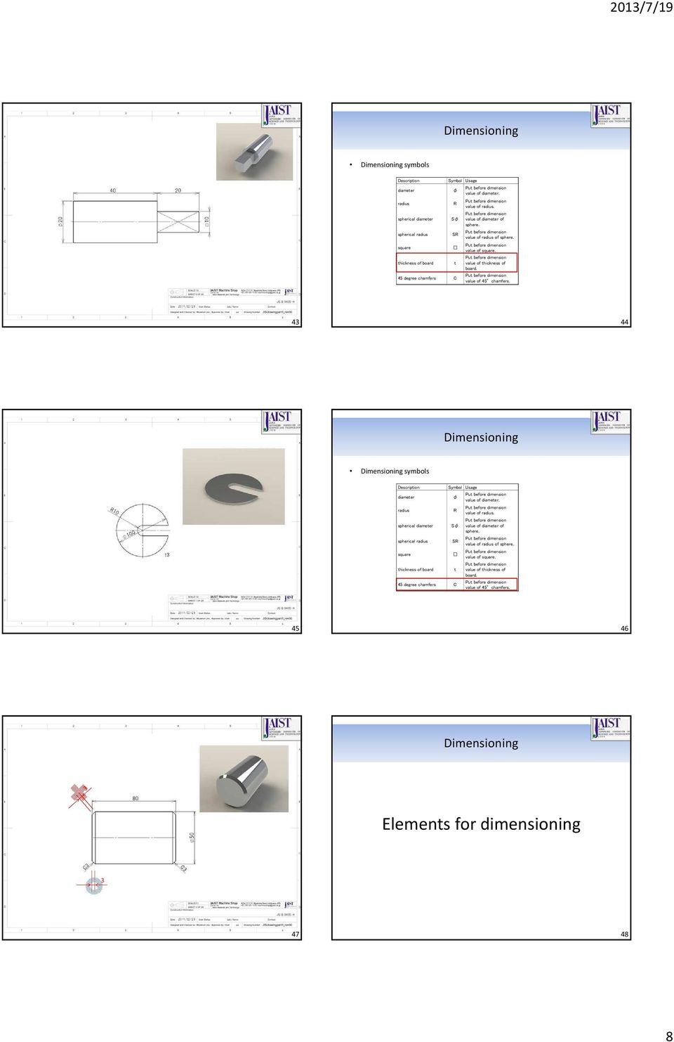
6 Dimensions are omitted Successive sections Detai drawings 3 32 Dimensioning Dimensioning Some dimensions are omitted Dimensioning symbos Description Symbo Usage diameter φ vaue of diameter. radius spherica diameter spherica radius R Sφ SR vaue of radius. vaue of diameter of sphere. vaue of radius of sphere. square vaue of square. thickness of board t vaue of thickness of board. 45 degree chamfers C vaue of 45 chamfers

7 Dimensioning Dimensions are omitted Dimensioning symbos Description Symbo Usage diameter φ vaue of diameter. radius spherica diameter spherica radius R Sφ SR vaue of radius. vaue of diameter of sphere. vaue of radius of sphere. square thickness of board t 45 degree chamfers C vaue of square. vaue of thickness of board. vaue of 45 chamfers. No arrow on the center point Dimensions are omitted Dimensioning Dimensioning symbos Description Symbo Usage diameter φ vaue of diameter. radius spherica diameter spherica radius R Sφ SR vaue of radius. vaue of diameter of sphere. vaue of radius of sphere. square vaue of square. thickness of board t vaue of thickness of board. 45 degree chamfers C vaue of 45 chamfers Dimensions are omitted Dimensioning Dimensioning symbos Description Symbo Usage diameter φ vaue of diameter. radius spherica diameter spherica radius R Sφ SR vaue of radius. vaue of diameter of sphere. vaue of radius of sphere. square vaue of square. thickness of board t vaue of thickness of board. 45 degree chamfers C vaue of 45 chamfers

8 Dimensioning Dimensioning symbos Description Symbo Usage diameter φ vaue of diameter. radius spherica diameter spherica radius R Sφ SR vaue of radius. vaue of diameter of sphere. vaue of radius of sphere. square vaue of square. thickness of board t vaue of thickness of board. 45 degree chamfers C vaue of 45 chamfers Dimensioning Dimensioning symbos Description Symbo Usage diameter φ vaue of diameter. radius spherica diameter spherica radius R Sφ SR vaue of radius. vaue of diameter of sphere. vaue of radius of sphere. square vaue of square. thickness of board t vaue of thickness of board. 45 degree chamfers C vaue of 45 chamfers Dimensioning Eements for dimensioning
9 Dimension vaue Dimensioning Dimension ine 3Termination arrow 4Projection ine 5Leader ine 6Reference ine 7Origin indicator Rues of dimensioning

10 55 56 Superimposed running dimensioning Dimension ine Outine Projection ine Center ine 59 6

11 Toerancing of Linear and Anguar Dimensions 6 62 Thank you. 63

12 Mechanica Engineering Drawing Workshop Screw Threads and Threaded Parts - Part : Genera Conventions (B2-) Content:. Drawing Screw Thread 2. ISO System of Limits and Fits 3. Genera Toerances 4. Symbos of Surface Texture JIS drawing part 2 2 Expression Expression Root Figure Crest Root Crest Figure 2 3 Figure 3 Figure 4 4 Expression Dimensioning Externa thread Figure 5 Figure 7 Figure 6 5 6

13 Dimensioning Interna thread ISO System of Limits and Fits -Part:Bases of Toerances, Deviations and Fits (B4) Figure 8 (front view) Figure 9 (front view) Figure (top view) These 3 figures show the same tapped hoe. 7 8 ISO System of Limits and Fits -Part:Bases of Toerances, Deviations and Fits ISO System of Limits and Fits -Part:Bases of Toerances, Deviations and Fits 9 ISO System of Limits and Fits -Part:Bases of Toerances, Deviations and Fits Hoe Toerance cass. Datum dimension Toerance cass Φ25 G 6 = φ (Φ25.7 ~ φ25.2) toerance zone Standard toerance grade 2 2

14 Hoe (Toerance Zone) Hoe( Size Toerance ) Φ25 G 6 Datum dimension (24~3) Datum Dimension (mm) Vaue of fundamenta deviation Lower deviation A of the standard toerance grades over to A B C CD D E EF F FG G H JS toerance zone (μm) +standard toerance/2 toerance zone Toerance zone Size toerance 3 Φ25 G 6 Datum dimension (8~3) Datum Dimension(mm) Standard toerance grade Standard toerance grade over to Size toerance(μm) Toerance zone.3 Size toerance (Φ25.7 ~ φ25.2) 4 Shaft Shaft (Toerance Zone ) Toerance cass Toerance cass Φ25 h 6 Datum dimension toerance zone Standard toerance grade = φ (φ ~ φ25.) Φ25 h 6 Datum dimension (24~3) Datum Dimension (mm) Vaue of fundamenta deviation Lower deviation A of the standard toerance grades over to a b c cd d e ef f fg g h js toerance zone (μm) +standard toerance/2 Size toerance toerance zone Shaft ( Size Toerance ) ISO System of Limits and Fits -Part:Bases of Toerances, Deviations and Fits Φ25 h 6 Standard toerance grade Size toerance Datum dimension (8~3) Datum Dimension(mm) Standard toerance grade over to Size toerance(μm) φ25g6 φ25h6 (φ ~ φ25.) 7 8 3
 +standard toerance/2 toerance zone Toerance zone Size toerance 3 Φ25 G 6 Datum dimension (8~3) Datum Dimension(mm) Standard toerance grade Standard toerance grade 2 3 4 5 6 7 8 9 over to Size")
15 9 2 Tabe of Genera Fit System Combinations Reference of Fit System Combination Tabe : Hoe basis system of fits Tabe 2: Shaft basis system of fits Base hoe H6 H7 H8 H9 H Base shaft h5 h6 h7 h8 h9 Toerance cass of shaft Cearance fit g5 h5 f6 g6 h6 f6 g6 h6 e7 f7 h7 f7 h7 e8 f8 h8 d9 e9 d8 e8 h8 c9 d9 e9 h9 b9 c9 d9 Toerance cass of hoe Cearance fit H6 F6 G6 H6 F7 G7 H7 F7 H7 E7 F8 H8 D8 E8 F8 H8 D9 E9 H9 D8 E8 H8 D9 E9 H9 C9 B C D Toerance zone Zero ine Datum dimension 2 Base hoe H6 H7 H8 H9 f6 g5 h5 h6 f7 g6 h6 d9 e8 f7 f8 h7 h8 c9 d9 h9 Cassification Needs sufficient gap. (expansion, toerance, fitting ength) Rotating parts, or siding parts. Fitting parts which are often taken apart. Need detaied action. Tabe 3 22 Genera Toerances Genera Toerances -Part:Toerances for Linear and Anguar Dimensions without Individua Toerance Indications (B45) Standard Toerance Grade Datum Dimension over 3 over from.5 over 3 over 6 2 over 4 over Symbo Meaning to 3 to 6 to 3 to 2 to 4 to to 2 Limit deviations f fine ±.5 ±.5 ±. ±.5 ±.2 ±.3 ±.5 m medium ±. ±. ±.2 ±.3 ±.5 ±.8 ±.2 c coarse ±.2 ±.3 ±.5 ±.8 ±.2 ±2 ±3 v very coarse - ±.5 ± ±.5 ±2.5 ±4 ±6 Tabe 4: Permissibe dimensiona deviation of ength without chamfer. 23 Standard Toerance Datum Dimension Grade from.5 over 3 over 6 Symbo Meaning to 3 to 6 Limit deviations f fine ±.2 ±.5 ± m medium c coarse ±.4 ± ±2 v very coarse Tabe 5: Permissibe dimensiona deviation of ength of chamfer. 24 4
 Rotating parts, or siding parts. Fitting parts which are often taken apart. Need detaied action.")
16 Genera Toerances Indication on a Drawing Standard Toerance Datum Dimension of Shorter Side of Target Ange JIS B standard toerance grade or under over over 5 over 2 over 4 Symbo Meaning to 5 to 2 to 4 Limit Deviations f fine ± ±3 ±2 ± ±5 m medium c coarse ± 3 ± ±3 ±5 ± v very coarse ±3 ±2 ± ±3 ±2 Tabe 6: Deviation Limits of Ange Symbos of Surface Texture Geometrica Product Specifications (GPS) -Indication of Surface Texture in Technica Product Specification (B3) Symbo of basic indication of surface texture Figure : Basic symbo Indication about removed process Figure 2: Remova processing is needed. Figure 3: Remova processing is not aowed. 27 Figure 4: Either is OK. 28 Symbo of Surface Texture Symbo of indication of round surface texture Indication of Surface Texture Ra: Arithmetic mean deviation Ra = f ( x) dx f(x):roughness profie : samping ength Figure 5: Round surface y f(x) 29 x 3 5

17 Indication of Surface Texture Indication of Surface Texture Ra: Arithmetic mean deviation Ra = f ( x) dx f(x):roughness profie : samping ength Ra: Arithmetic mean deviation Ra = f ( x) dx f(x):roughness profie : samping ength y y f(x) f(x) x x 3 32 Indication of Surface Texture Indication of Surface Texture Ra: Arithmetic mean deviation Ra = f ( x) dx f(x):roughness profie : samping ength Ra: Arithmetic mean deviation Ra = f ( x) dx f(x):roughness profie : samping ength y y f(x) f(x) x x Indication of Surface Texture Indication of Surface Texture Ra: Arithmetic mean deviation Ra = f ( x) dx f(x):roughness profie : samping ength Ra: Arithmetic mean deviation Ra = f ( x) dx f(x):roughness profie : samping ength y y f(x) R a f(x) x x

18 Indication of Surface Texture Indication of Surface Texture μm Tabe7: Standard vaues of Ra. Figure 6: Position Figure 7: Leader ine Bodface vaues have priority over the others Simpe Indication of Surface Texture Reference of Surface Texture Ra(μm) Function Finishing.5 mirror surface apping =..2.4 surface for siding O-ring.8 surface for O-ring fange.6 3.2~6.3 fits 2.5~25 5 emery paper fine machining eectrica discharge machining norma machining Figure 8: Simpe indication of a part of which most of the surfaces in the drawing have the same surface texture. 39 Tabe 8: Standard numbers of Ra. 4 Thank you 7

19 Mechanica Engineering Drawing Workshop Tips for design Necessary Knowedge of Actua Drawing and Design Techniques. 2 Corner R Corner R ( sampe hoder ) 3 4 Corner R ( sampe hoder ) Driing sampe sampe sampe
 3 4 Corner R ( sampe")
20 Wire-eectrica discharge machining Drawing-sampes of major parts 7 8 Screw thread Screw thread 9 Confat(CF) meta-sea fange ( reducer ) Confat(CF) meta-sea fange 2 2
 Confat(CF)")
21 Kwik-fange (KF) ( adapter ) Kwik-fange (KF) 3 4 O-ring sea O-ring sea 5 6 Mask Mask 7 8 3
22 Metric thread and inch thread Screws Standards Type of units Type of pitch metric coarse thread metric fine pitch thread UNC thread UNF thread metric thread inch thread coarse fine coarse Metric thread: Trianguar screw thread. Diameter and pitch are indicated as mm. 6 degrees thread ange. fine 9 Inch thread: Trianguar screw thread. Pitch is indicated as thread/inch. Coarse thread: Combination of diameter and pitch is genera and used most often. Fine thread: This thread type screw is used for specia uses. 2 Metric thread Metric thread Name of thread Pitch Priority Fine Coarse st 2nd 3rd Name of thread Pitch Priority Fine Coarse st 2nd 3rd (3) (3) UNC thread UNC thread Name of thread Thread/inch Pitch Diameter st priority 2nd priority No UNC No UNC No UNC No. 4-4 UNC No. 5-4 UNC No UNC No UNC No UNC No UNC /4-2 UNC 5/6-8 UNC /8-6 UNC /6-4 UNC /2-3 UNC /6-2 UNC /8 - UNC /4 - UNC /8-9 UNC Name of thread Thread/inch Pitch Diameter st priority 2nd priority - 8 UNC UNC /8 /4-7 UNC /8-6 UNC /2-6 UNC /4-5 UNC 4 / /2 UNC 4 / /2 UNC /4 2 /2-4 UNC /4-4 UNC UNC UNC /4 3 /2-4 UNC /4-4 UNC UNC
23 UNF thread UNF thread st priority Name of thread 2nd priority Thread/inch Pitch Diameter st priority Name of thread 2nd priority Thread/inch Pitch Diameter No. - 8 UNF No UNF No UNF No UNF No UNF No UNF No. 6-4 UNF No UNF No UNF No UNF /4-28 UNF 5/6-24 UNF No. - 8 UNF No UNF No UNF No UNF No UNF No UNF No. 6-4 UNF No UNF No UNF No UNF /4-28 UNF 5/6-24 UNF Interna thread Fanges for vacuum Confat(CF) meta-sea fange Standard of confat(cf) meta-sea fange Confat meta-sea fange is patented by Varian. This fange is used for UHV ( -6 Pa~). Usuay, they are caed ICF + diameter of fange, for exampe ICF7. (mm) Diameter Thickness Bot hoe Pipe to wed D T Quantity h C O.D d I.D. d
24 JIS fange ( VF/VG ) Standard of JIS fange Features O-ring seaing There are VG type and VF type fanges. VG has gasket groove. VF has no gasket groove. Used from ow vacuum to high vacuum. They are caed VF7, VG2, etc. Thickness Bot hoes Groove Diameter Pipe O.D. Name T Diameter P.C.D. I.D. O.D. Depth D Quantity d Casting Other h C G G2 S Bock for item ist Tips for actua drawing Bock for item ist e.g. Reference number, part name, materia, quantity, note etc. Tite bock e.g. Drawing number, tite, company or group name, cient s name, date, scae, projection method, genera toerance etc. Bock for item ist Tite bock Part drawing and assemby drawing Assemby drawing. Part drawings ony Reference numbers Weding symbo 2. Assemby drawings require Part drawings Bock for item ist Tite bock 35 Dimensions needed for assemby 36 6
25 Part drawing Practice Fit with the fange
26 = 4 5.8dri φ
27 Thank you Reference List: wikipedia.org (Engish page) Kenkyusha Onine Dictionary Pau Green. The Mechanica Engineering Drawing Desk Reference. 9
Working Drawing and Assemblies. Chapter 10
 Working Drawing and Assemblies Chapter 10 Objectives 1.Define working drawings. 2. Describe how working drawings are used in industry. 3. List the major components of a complete set of working drawings.
DESCRIPTION. Stud Bolts for Pressure-Temperature Piping 2-1. General Purpose End-to-End Studs 2-2. Tap End Stud Bolts 2-3. Double End Stud Bolts 2-4
 DESCRIPTION PAGE B7 Studs and Nuts Stud Bolts for Pressure-Temperature Piping 2-1 General Purpose End-to-End Studs 2-2 Tap End Stud Bolts 2-3 Double End Stud Bolts 2-4 Sigma Fasteners, Inc. Section 2 STUD
SCREW THREADS C H A P T E R 17
 C H A P T E R 17 SCREW THREADS Screw threads are of prime importance in machine drawing. It is a functional element used as temporary fasteners such as bolt, stud, nut and screw etc. These are constructed
Removing chips is a method for producing plastic threads of small diameters and high batches, which cause frequent failures of thread punches.
 Plastic Threads Technical University of Gabrovo Yordanka Atanasova Threads in plastic products can be produced in three ways: a) by direct moulding with thread punch or die; b) by placing a threaded metal
The width of single glazing. The warmth of double glazing.
 Therma Insuation CI/SfB (31) Ro5 (M5) September 2012 The width of singe gazing. The warmth of doube gazing. Pikington Spacia Revoutionary vacuum gazing. Image courtesy of Lumen Roofight Ltd. Pikington
American National, Unified Screw Threads
 C h a p t e r 9 American National, Unified Screw Threads In this chapter, you will learn the following to World Class standards:! Why Use Fasteners! The Text Designation for the Unified National Thread!
Thread and End Connection
 www.swagelok.com and End Connection Identification Guide 2 Contents Introduction and End Connection Terminology.. 4 General Terminology... 5 Step-by-Step Identification Procedure for s and End Connections...
1 Basic concepts in geometry
 1 asic concepts in geometry 1.1 Introduction We start geometry with the simpest idea a point. It is shown using a dot, which is abeed with a capita etter. The exampe above is the point. straight ine is
Some additional standards and specifications that directly or indirectly affect surface finish requirements include:
 Surface Finish Charts Surface Finish Affects Performance The surface finish of process vessels, piping and related components can be a critical factor in their performance, maintenance costs, and service
UNITED STATES CUTTING TOOL INSTITUTE Product Groupings for Standards Activities CUTTING TOOL PRODUCTS
 CUTTING TOOL PRODUCTS 1. BORING ISO 5609 Boring bars for indexable inserts Dimensions ISO 6261 Boring bars (tool holders with cylindrical shank) for indexable inserts Designation JIS B 4128 Boring bars
DRAFTING MANUAL. Gears (Bevel and Hypoid) Drafting Practice
 Drafting Practice") Page 1 1.0 General This section provides the basis for uniformity in engineering gears drawings and their technical data for gears with intersecting axes (bevel gears), and nonparallel, nonintersecting
Page 1 1.0 General This section provides the basis for uniformity in engineering gears drawings and their technical data for gears with intersecting axes (bevel gears), and nonparallel, nonintersecting
Data sheet. June 2000 DKACT.PD.P10.F1.02 520B0370
 Pressure contros and thermostats types KPI and KP June 2000 DKACT.PD.P10.F1.02 520B0370 Pressure contros and thermostats, types KPI and KP Contents Pressure contros KP 35, KP 36, KPI 35, KPI 36 and KPI
ISO 1101 Geometrical product specifications (GPS) Geometrical tolerancing Tolerances of form, orientation, location and run-out
 Geometrical tolerancing Tolerances of form, orientation, location and run-out") INTERNATIONAL STANDARD ISO 1101 Third edition 2012-04-15 Geometrical product specifications (GPS) Geometrical tolerancing Tolerances of form, orientation, location and run-out Spécification géométrique
INTERNATIONAL STANDARD ISO 1101 Third edition 2012-04-15 Geometrical product specifications (GPS) Geometrical tolerancing Tolerances of form, orientation, location and run-out Spécification géométrique
VCE VET ENGINEERING STUDIES
 Victorian Certificate of Education 2013 SUPERVISOR TO ATTACH PROCESSING LABEL HERE STUDENT NUMBER Letter Figures Words VCE VET ENGINEERING STUDIES Written examination Section Wednesday 20 November 2013
Measurement of Length, Mass, Volume and Density
 Measurement of Length, Mass, Volume and Density Experimental Objective The objective of this experiment is to acquaint you with basic scientific conventions for measuring physical quantities. You will
Technical Drawing Specifications Resource A guide to support VCE Visual Communication Design study design 2013-17
 A guide to support VCE Visual Communication Design study design 2013-17 1 Contents INTRODUCTION The Australian Standards (AS) Key knowledge and skills THREE-DIMENSIONAL DRAWING PARALINE DRAWING Isometric
Chapter 6 Machining Center Carbide Insert Fundamentals
 This sample chapter is for review purposes only. Copyright The Goodheart-Willcox Co., Inc. All rights reserved. N10G20G99G40 N20G96S800M3 N30G50S4000 N40T0100M8 N50G00X3.35Z1.25T0101 N60G01X3.25F.002 N70G04X0.5
SolidWorks Tutorial 3 MAGNETIC BLOCK
 SolidWorks Tutorial 3 MAGNETIC BLOCK Magnetic Block In this exercise you will make a magnetic block. To do so, you will create a few parts, which you will assemble. You will learn the following new applications
Industrial: Flare Fittings
 Industria: Fare Fittings SAE 45 Fare Resists echanica Pu-out eets SAE Functiona Requirements Resists Vibration U isted Inverted Fare Stee ut option Economica U isted Access Vaves Finger Tight Quick Sea
Manifold Technology. ----------------------------------------------------- made in Germany
 Manifod Technoogy. ----------------------------------------------------- made in Germany I EVERYTHING UNDER CONTROL. Manifod Technoogy BEULCO heating and cooing manifods made of high-quaity brass ensure
7. Dry Lab III: Molecular Symmetry
 0 7. Dry Lab III: Moecuar Symmetry Topics: 1. Motivation. Symmetry Eements and Operations. Symmetry Groups 4. Physica Impications of Symmetry 1. Motivation Finite symmetries are usefu in the study of moecues.
Screw Thread Design. Rev. 3-4-09
 Screw Thread Design Screw Thread Fundamentals A screw thread is defined as a ridge of uniform section in the form of a helix on either the external or internal surface of a cylinder. Internal threads refer
Making 3D Threads in Feature Based Solid Modelers
 Making 3D Threads in Feature Based Solid Modelers THREAD BASICS Making true geometric threads in feature-based solid modelers is a fairly straightforward process and can be handled using several different
Standards for Working Drawings
 Standards for Working Drawings 27 August 2013 Department of Mechanical and Mechatronic Engineering and Sustainable Manufacturing California State University, Chico Chico, California 95929-0789 Contents
Technical product documentation and specification
 BS 8888:2011 BSI Standards Publication Technical product documentation and specification NO COPYING WITHOUT BSI PERMISSION EXCEPT AS PERMITTED BY COPYRIGHT LAW raising standards worldwide BS 8888:2011
Power-D-Box Printed Circuit Board Version for 2216/REF16
 Power-D-Box Printed Circuit Board Version for 226/REF6 Description The Power-D-Box based on a is a compact power distribution system, designed as a 9" 2U rack made of auminium profies with anodised front
Physics 100A Homework 11- Chapter 11 (part 1) The force passes through the point A, so there is no arm and the torque is zero.
 The force passes through the point A, so there is no arm and the torque is zero.") Physics A Homework - Chapter (part ) Finding Torque A orce F o magnitude F making an ange with the x axis is appied to a partice ocated aong axis o rotation A, at Cartesian coordinates (,) in the igure.
Physics A Homework - Chapter (part ) Finding Torque A orce F o magnitude F making an ange with the x axis is appied to a partice ocated aong axis o rotation A, at Cartesian coordinates (,) in the igure.
ABERLINK 3D MKIII MEASUREMENT SOFTWARE
 ABERLINK 3D MKIII MEASUREMENT SOFTWARE PART 1 (MANUAL VERSION) COURSE TRAINING NOTES ABERLINK LTD. EASTCOMBE GLOS. GL6 7DY UK INDEX 1.0 Introduction to CMM measurement...4 2.0 Preparation and general hints
Milling. COPYRIGHT 2008, Seco Tools AB 1/111
 Milling 1/111 2/111 Milling A simple choice! Experts required? No Just follow some basic rules. 3/111 Face milling 4/111 Square shoulder milling 5/111 Disc milling 6/111 Copy milling 7/111 Plunge milling
Presentation. KEYTECH S.r.L. Business Unit
 KEYTECH S.r.. Presentation KEYTECH S.r.L. Business Unit KEYTECH S.r.. The Company KEYTECH s.r. - Business Unit: Morro d Aba Engineering Components (Pastics, Stee and Rubber) ITALY Engineering Tooing (Pastics,
How To Retaining Wall Guide
 How To Retaining Wall Guide Before you start: Consents and Engineering Building Consent Retaining walls over 1.5m high will require a building consent from the Local Body Council. Walls that carry extra
Fasteners and screw threads
 ISO Standards Handbook: Fasteners and screw threads Volume 2: Product standards Contents Part 3 : Product standards 2001, Ed. 5, 1094 p., ISBN 92-67-10345-8 3.1 External drive hexagon head bolts and screws
TECHNICAL SPECIFICATION SERIES 8000 PRECAST CONCRETE
 TECHNICAL SPECIFICATION SERIES 8000 PRECAST CONCRETE TECHNICAL SPECIFICATION PART 8000 - PRECAST CONCRETE TABLE OF CONTENTS Item Number Page 8100 PRECAST CONCRETE CONSTRUCTION - GENERAL 8-3 8101 General
Features and benefits
 Showermate provides a range of high quaity, high performing, pastic shower pumps. Designed to boost the performance of shower and tap outets within a bathroom. The range is suitabe for positive and negative
Freehand Sketching. Sections
 3 Freehand Sketching Sections 3.1 Why Freehand Sketches? 3.2 Freehand Sketching Fundamentals 3.3 Basic Freehand Sketching 3.4 Advanced Freehand Sketching Key Terms Objectives Explain why freehand sketching
ME 1355 CAD/CAM LABORATORY CNC MILLING PROGRAM. Study of G Codes and M Codes to Write Manual Part Programming for Fanuc Control Systems
 ME 1355 CAD/CAM LABORATORY CNC MILLING PROGRAM Ex.No.1 Study of G Codes and M Codes to Write Manual Part Programming for Fanuc Control Systems PREPARATORY FUNCTION ( G CODES ) The preparatory functions
Gear Engineering Data. Spur Gear Gear Formulas Drive Selection Horsepower and Torque Tables
 Engineering Gear Engineering Data Spur Gear Gear Formulas Drive Selection Horsepower and Torque Tables G-79 Gear Selection Stock Spur Gear Drive Selection When designing a stock gear drive using the horsepower
Fastener Handout. Introduction: Engineering Design Representation 2. Threads 2. Local Notes (callouts) 8. Threaded Mechanical Fasteners 13
 8. Threaded Mechanical Fasteners 13") Fastener Handout Introduction: Engineering Design Representation 2 Threads 2 Effect of thread angle on strength: 3 Standardization of Threads: 4 Descriptions of the Thread Series: 4 Class fit: 5 Specification
Fastener Handout Introduction: Engineering Design Representation 2 Threads 2 Effect of thread angle on strength: 3 Standardization of Threads: 4 Descriptions of the Thread Series: 4 Class fit: 5 Specification
Measuring Devices 10/1 10/2. Introduction. 10/4 7KT5 8 time and pulse counters. 10/6 7KT5 5 and 7KT5 6 time counters for front-panel mounting
 0 0/2 Measuring Devices Introduction 0/4 7T5 8 time and puse counters 0/6 7T5 5 and 7T5 6 time counters for front-pane mounting 0/8 7T 0 anaog measuring devices 0/0 7T digita measuring devices 0/ 7T 30
PIPING SYSTEM - ABRASIVE SLURRIES Engineering Standard Specification. 96 B. Riutta
 PIPING SYSTEM - ABRASIVE SLURRIES Engineering Standard Specification Number: 3503-11.2.610 Rev. 2 Rubber Lined Steel Pipe and Fittings Mechanically Coupled Plain End Type System Issued Revised Approved
Introduction to XSL. Max Froumentin - W3C
 Introduction to XSL Max Froumentin - W3C Introduction to XSL XML Documents Stying XML Documents XSL Exampe I: Hamet Exampe II: Mixed Writing Modes Exampe III: database Other Exampes How do they do that?
Traditional Drawing Tools
 Engineering Drawing Traditional Drawing Tools DRAWING TOOLS DRAWING TOOLS 1. T-Square 2. Triangles DRAWING TOOLS HB for thick line 2H for thin line 3. Adhesive Tape 4. Pencils DRAWING TOOLS 5. Sandpaper
Pipe Thread Types and Designations
 Pipe Thread Types and Designations Overview: Different types of screw threads have evolved for fastening, and hydraulic systems. Of special concern are plastic-to-metal, taper/parallel threaded joints
CI/SfB Ro8. (Aq) September 2012. The new advanced toughened glass. Pilkington Pyroclear Fire-resistant Glass
 September 2012. The new advanced toughened glass. Pilkington Pyroclear Fire-resistant Glass") CI/SfB Ro8 (Aq) September 2012 The new advanced toughened gass Pikington Pyrocear Fire-resistant Gass Pikington Pyrocear, fire-resistant screens in the façade: a typica containment appication for integrity
CI/SfB Ro8 (Aq) September 2012 The new advanced toughened gass Pikington Pyrocear Fire-resistant Gass Pikington Pyrocear, fire-resistant screens in the façade: a typica containment appication for integrity
CALCULATION & DRAFTING STANDARDS MANUAL PROCEDURE: C&D 515 Bill of Materials Standard REV 0.0 5/6/04
 BROWN MINNEAPOLIS TANK PAGE 1 OF 7 PURPOSE: Create and Drawing Uniformity Create, explain, and establish a standard bill of materials to be placed on every drawing (except the overall tank elevation and
SAT Math Facts & Formulas
 Numbers, Sequences, Factors SAT Mat Facts & Formuas Integers:..., -3, -2, -1, 0, 1, 2, 3,... Reas: integers pus fractions, decimas, and irrationas ( 2, 3, π, etc.) Order Of Operations: Aritmetic Sequences:
Technical Data. 7. Bearing Fits. 7.1 Interference. 7.2 Calculation of interference F B LLLLLLLLL( A-54
 Technical Data 7. Bearing Fits 7.1 Interference For rolling s the rings are fixed on the or in the housing so that slip or movement does not occur between the mated surface during operation or under. This
GOST 632-80 CASING AND COUPLINGS
 GOST 632-80 CASING AND COUPLINGS Casing to this standard shall be seamless, with round and buttress-type threads (OTTM-type casing), with high-seal thread connection (OTTG-type casing) and respective couplings;
L-02 TOOLMAKER TRAINING TRAINER S GUIDE
 L-02 TOOLMAKER TRAINING TRAINER S GUIDE Duty L: External Grinder L-02: Grind Surfaces Issued 06/01/98 Instructions To The Trainer 1. The Learner will contact you when ready to practice grinding the surface
INDUSTRIAL AND COMMERCIAL
 Finance TM NEW YORK CITY DEPARTMENT OF FINANCE TAX & PARKING PROGRAM OPERATIONS DIVISION INDUSTRIAL AND COMMERCIAL ABATEMENT PROGRAM PRELIMINARY APPLICATION AND INSTRUCTIONS Mai to: NYC Department of Finance,
TL-Series Sub-Spindle Operator s Addendum
 3 4 5 11 9 TL-Series Sub-Spindle Operator s Addendum 2 1 12 10 6 7 8 20HP VECTOR DUAL DRIVE LIVE TOOLING SUB SPINDLE 2008 Haas Automation, Inc. 96-0037 rev L 9/08 1 1. Introduction Specific M codes are
SolidWorks: Mirror, Revolve, and. Introduction to Robotics
 SolidWorks: Mirror, Revolve, and Circular Pattern Introduction to Robotics Let s Review At this point we have learned the following: Extrude Boss/Base Extruded Cut Adding Relations and Dimensions Linear
READING A CREDIT REPORT
 Name Date CHAPTER 6 STUDENT ACTIVITY SHEET READING A CREDIT REPORT Review the sampe credit report. Then search for a sampe credit report onine, print it off, and answer the questions beow. This activity
SELF-CLINCHING STANDOFFS BULLETIN
 SEF-INING STANDOFFS BUETIN SO 1214 SEF-INING STANDOFFS PEM self-clinching standoffs, which use the proven self-clinching design, provide ideal solutions for applications where mounting, spacing or stacking
SKF Supergrip. Alignment tools
 SKF Supergrip Aignment toos SKF Supergrip aignment too Creates a perfect fit between the bot hoes Funny thing! Here you come to accept oi power-instaed expansion bots for your turbine fange couping as
3.3 SOFTWARE RISK MANAGEMENT (SRM)
") 93 3.3 SOFTWARE RISK MANAGEMENT (SRM) Fig. 3.2 SRM is a process buit in five steps. The steps are: Identify Anayse Pan Track Resove The process is continuous in nature and handed dynamicay throughout ifecyce
93 3.3 SOFTWARE RISK MANAGEMENT (SRM) Fig. 3.2 SRM is a process buit in five steps. The steps are: Identify Anayse Pan Track Resove The process is continuous in nature and handed dynamicay throughout ifecyce
An Idiot s guide to Support vector machines (SVMs)
") An Idiot s guide to Support vector machines (SVMs) R. Berwick, Viage Idiot SVMs: A New Generation of Learning Agorithms Pre 1980: Amost a earning methods earned inear decision surfaces. Linear earning
An Idiot s guide to Support vector machines (SVMs) R. Berwick, Viage Idiot SVMs: A New Generation of Learning Agorithms Pre 1980: Amost a earning methods earned inear decision surfaces. Linear earning
EJOT Spiralform. The thread formers for metal. EJOT The Quality Connection
 EJOT Spiralform The thread formers for metal EJOT The Quality Connection Imprint Editor: EJOT GmbH & Co. KG Industrial Fasteners Division D 57319 Bad Berleburg Layout and Realisation: EJOT GmbH & Co. KG
Setting up the DeskCNC controller.
 1) Determine the steps to linear motion ratios for each axis. 2 2) Determine Maximum velocity (speed). 3 3) Setting up the software Machine Tab 4 4) Setting up the software DeskCNC Setup Tab 5 5) Setting
SpaceClaim Introduction Training Session. A SpaceClaim Support Document
 SpaceClaim Introduction Training Session A SpaceClaim Support Document In this class we will walk through the basic tools used to create and modify models in SpaceClaim. Introduction We will focus on:
Lecture slides on rolling By: Dr H N Dhakal Lecturer in Mechanical and Marine Engineering, School of Engineering, University of Plymouth
 Lecture slides on rolling By: Dr H N Dhakal Lecturer in Mechanical and Marine Engineering, School of Engineering, University of Plymouth Bulk deformation forming (rolling) Rolling is the process of reducing
ICAP CREDIT RISK SERVICES. Your Business Partner
 ICAP CREDIT RISK SERVICES Your Business Partner ABOUT ICAP GROUP ICAP Group with 56 miion revenues for 2008 and 1,000 empoyees- is the argest Business Services Group in Greece. In addition to its Greek
Energy Performance Certificate
 Energy Performance Certificate Sampe EPC TheDomesticEnergyAssessorcom Dweing type: Date of assessment: Date of certificate: Reference number: Tota foor area: Mid-terrace house 09 June 2007 31 August 2007
Die casting Figure M2.3.1
 Die casting Die casting is a moulding process in which the molten metal is injected under high pressure and velocity into a split mould die. It is also called pressure die casting. The split mould used
For mechanical & hydraulic presses Inch & metric taps
 www.danly.com TRUSTED SOLUTIONS AND INNOVATION Professional IDT TM In-Die Tapping Catalog For mechanical & hydraulic presses Inch & metric taps www.danly.com Professional IDT TM In-Die Tapping Service
Quantum Energy Generator
 Quantum Energy Generator VERSION: 1.02 LAST UPD: 4 JULY 2014 CONTACT: [email protected] Introduction: This document contains the manufacturing drawings for the QEG: Quantum Energy Generator. The design
SENTINEL SERIES MICRO-MATIC STUD DRIVER WITH TORQUE CONTROL
 SERIES MICRO-MATIC STUD DRIVER WITH TORQUE CONTROL 1. Drives studs to pre-determined torque. 2. Prevents stud or part damage when driving to shoulder or bottom of hole. 3. Quick releasing, non-reversing
Copyright 2008 OLYMPUS CORPORATION All Rights Reserved. Paper Craft Assembly Manual
 Paper Craft Assembly Manual Before assembly: 1/9 Tips on assembly: Print all the parts (Photo-quality paper is recommended for ink-jet printers and paper of medium thickness (0.20 mm) for laser printers.)
AISI CHEMICAL COMPOSITION LIMITS: Nonresulphurized Carbon Steels
 AISI CHEMICAL COMPOSITION LIMITS: Nonresulphurized Carbon Steels AISI No. 1008 1010 1012 1015 1016 1017 1018 1019 1020 1021 1022 1023 1024 10 1026 1027 1029 10 1035 1036 1037 1038 1039 10 1041 1042 1043
WINMAG Graphics Management System
 SECTION 10: page 1 Section 10: by Honeywe WINMAG Graphics Management System Contents What is WINMAG? WINMAG Text and Graphics WINMAG Text Ony Scenarios Fire/Emergency Management of Fauts & Disabement Historic
Engineering & Design: Coordinate Dimensioning
 s e c t i o n Section Contents NADCA No. Format Page Frequently Asked Questions (FAQ) -2 1 Introduction -2 2 Section Objectives -3 3 Standard and Precision Tolerances -3 4 Production Part Technologies
Advantages and Disadvantages of Sampling. Vermont ASQ Meeting October 26, 2011
 Advantages and Disadvantages of Samping Vermont ASQ Meeting October 26, 2011 Jeffrey S. Soomon Genera Dynamics Armament and Technica Products, Inc. Wiiston, VT 05495 Outine I. Definition and Exampes II.
Modeling Curved Surfaces
 Modeling Cylindrical and Curved Theory Views of Cylinders Contour Lines Extruded Surfaces Revolved Surfaces & Cutouts Profile Shape Axis of Revolution Swept Surfaces & Cutouts Profile Shape Path Curves
Perfect functionality whatever the function.
 match up For over 130 years, Sedus has been synonymous with innovative office furniture which not ony supports work at and around the desk, but aso makes it more productive. Take, for exampe, Sedus match
Micro Precision Tools Your partner for precision applications
 Micro Precision Tools Your partner for precision applications 2K Softgrip Micro Screwdrivers (page 72-73) Working in restricted areas is a particular problem especially in modern equipments, such as electronic
PROTOTYPE DESIGN AND MANUFACTURING MANUAL
 PROTOTYPE DESIGN AND MANUFACTURING MANUAL DEPARTMENT OF MECHANICAL ENGINEERING RODNEY KATZ Rev. 0 TABLE OF CONTENTS Introduction... 1 PART I - Design... 2 1 First Step to Design... 2 2 Prototyping... 3
Module 2 GEARS. Lecture 3 - INVOLUTE SPUR GEARS
 Module 2 GEARS Lecture 3 - INVOLUTE SPUR GEARS Contents 3.1 Introduction 3.2 Standard tooth systems for spur gears 3.3 Profile shifted gears 3.4 Involutometry 3.5 Design of gear blanks 3.1 INTRODUCTION
Drawn Cup Needle Roller Bearings
 Drawn up Needle Roller Bearings NSK has introduced the most advanced bearing technology, offering unprecedented precision and reliability. Available in two types caged and full complement. High-quality
How to Build Your Own CornHole Game
 How to Build Your Own CornHole Game DIMENSIONS Here is a diagram with the basic measurements for the Cornhole board game. SUPPLIES 1/2 thick sheet of plywood one 4 x4 or two 2 x4 s 8 long 2 4 s (4) 4 1/2
Technical Product Specification (TPS)
") ISO Standards collection Technical Product Specification (TPS) Contents ISO 1:2002 Geometrical Product Specifications (GPS) -- Standard reference temperature for geometrical product specification and verification
ISO Standards collection Technical Product Specification (TPS) Contents ISO 1:2002 Geometrical Product Specifications (GPS) -- Standard reference temperature for geometrical product specification and verification
Pilkington K Glass Range. Pilkington K Glass Pilkington K Glass OW Pilkington K Glass OW on Surface 4 Pilkington K Glass S
 Pikington K Gass Range Pikington K Gass Pikington K Gass OW Pikington K Gass OW on Surface 4 Pikington K Gass S Upstairs windows using energy-efficient gazing. Downstairs windows using origina singe gazing.
THRUST NEEDLE ROLLER AND CAGE ASSEMBLIES Assembly Dimensions, Load Ratings, Thrust Washer and Piloting Dimensions... 480-487
 Thrust Bearings Page Nomenclature............................................ 474 Introduction............................................. 476 Identification.............................................
800-348-8467 www.fittingsunlimited.com
 Thread and Port Identification Guide 800-348-8467 www.fittingsunlimited.com INDEX Index... 1 Explanation of Symbols... 2 How to Measure Threads... 3-4 Metric vs English Threads... 5 North American Connections
Pneumatic Grippers Parallel and Angular Grippers. Catalog 1900-2/US
 Pneumatic Grippers Parallel and Angular Grippers Catalog 19-2/US Catalog 19-2/US OContents GPR Series Rotary vane driven design GPR GPCR Series P5G-HPM(C) Series P5G-HP Series GPT Series P5G-AP Series
5. Introduction to Robot Geometry and Kinematics
 V. Kumar 5. Introduction to Robot Geometry and Kinematics The goa of this chapter is to introduce the basic terminoogy and notation used in robot geometry and kinematics, and to discuss the methods used
SHOP NOTES METAL SHAPER FOR YOUR SHOP
 SHOP NOTES METAL SHAPER FOR YOUR SHOP A METAL SHAPER is indispensable for certain machining operations where flat surfaces must be produced within very close limits, such as machining flats on castings,
Lamination Production. by: John Roberts / Sko Die, Inc
 Lamination Production by: John Roberts / Sko Die, Inc Presentation Mission Understand the construction for magnetic cores Chose the best methods for producing Magnetic cores are constructed From soft magnetic
Butt Fusion Welding of HDPE Pipes Work Procedure
 Butt Fusion Welding of HDPE Pipes Work Procedure A pipeline is as good as its weakest point. Accordingly it is not only important that quality pipes and components are used in a piping system, but also
SCHMIDT ManualPress 300 Series Manual Presses with Process Monitoring
 Manual Presses with Process Monitoring Process reliability, force/stroke monitoring of the joining process and EN ISO- compatible documentation of the results are becoming the major factors for small and
Hilti, Inc. 5400 South 122 nd East Avenue Tulsa, OK 74146. 1-800-879-8000 www.hilti.com
 Attached are page(s) from the 2014 Hilti North American Product Tech Guide. For complete details on this product, including data development, product specifications, general suitability, installation,
LINEAR MOTION CONTROL
 LINEAR MOTION CONTROL Technical Data Sheet Static Locks RLSS Series Nexen s new generation of linear holding/locking devices take rod locking technology to the next level. With superior performance, these
METALWORKING PRODUCTS. Deep hole drilling Product catalogue and application guide
 METALWORKING PRODUCTS Deep hole drilling Product catalogue and application guide AB Sandvik Coromant Not only a tool supplier Sandvik Coromant is the No.1 supplier of cutting tools for the metalworking
Metric System & Specifications
 Metric System & Specifications Throughout history, people have been trying to limit the number of measurement systems. Today, only two systems, inch-pound and metric, are predominate in most industrial
Machine Screws, Dowel Pins and Hardware
 Machine Screws, Dowel Pins and Section Contents Plain Socket Head Screws...Page 13-2 Wire Locking Screws...Page 13-3 Captive Screws...Page 13- Ventilation Screws...Page 13- Shoulder Screws...Page 13-
PRESSURE REDUCING VALVES
 0E0-GB PRESSURE REDUCING VAVES MAIN FEATURES The pressure reducing valve is able, by varying its pressure drops, to hold the downstream pressure of the fluid at a constant level against changes in the
MAGNETIC CARD READER DESIGN KIT TECHNICAL SPECIFICATION
 MAGNETIC CARD READER DESIGN KIT TECHNICAL SPECIFICATION Part Number: 99821002 Rev 21 FEBRUARY 2011 REGISTERED TO ISO 9001:2008 1710 Apollo Court Seal Beach, CA 90740 Phone: (562) 546-6400 FAX: (562) 546-6301
Heat Transfer Prof. Dr. Aloke Kumar Ghosal Department of Chemical Engineering Indian Institute of Technology, Guwahati
 Heat Transfer Prof. Dr. Aloke Kumar Ghosal Department of Chemical Engineering Indian Institute of Technology, Guwahati Module No. # 02 One Dimensional Steady State Heat Transfer Lecture No. # 05 Extended
Working Pressure - Hose Ends
 Working Pressure - Hose Ends The maximum dynamic working pressure of a hose assembly is the lesser of the rated working pressure of the hose and the end connection used. HIGH SPECIALTY HOSE ACCESSORRIES
Introduction to Autodesk Inventor for F1 in Schools
 Introduction to Autodesk Inventor for F1 in Schools F1 in Schools Race Car In this course you will be introduced to Autodesk Inventor, which is the centerpiece of Autodesk s digital prototyping strategy