Working Drawing and Assemblies. Chapter 10
|
|
|
- Lesley McCormick
- 7 years ago
- Views:
Transcription
1 Working Drawing and Assemblies Chapter 10

2 Objectives 1.Define working drawings. 2. Describe how working drawings are used in industry. 3. List the major components of a complete set of working drawings. 4. Describe the differences between detail and assembly drawings. 5. Describe how part numbers, zoning, and tables are used on working drawings. 6. Draw standard representation of threads.

3 Objectives 7. Specify a metric or English thread in a note. 8. Use the graphic language of mechanisms such as gears, cams, bearings, and linkages. 9. Interpret the specialized graphic language used in piping and welding drawings. 10. Describe how CAD is used to create, store, and retrieve working drawings. 11. List techniques used to create copies of engineering drawings.

4 Working Drawings Working drawings are the complete set of standardized drawings specifying the manufacture and assembly of a product based on its design.

5 Working Drawings The complexity of the design determines the number and types of drawings. Working drawings may be on more than one sheet and may contain written instructions called specifications.

6 Working Drawings Working drawings are the blueprints used for manufacturing products. Therefore, the set of drawings must: completely describe the parts, both visually and dimensionally show the parts in assembly identify all the parts specify standard parts.

7 Working Drawings A complete set of working drawings for an assembly include: detail drawings of each nonstandard part. an assembly or subassembly drawing showing all the standard and nonstandard parts in a single drawing. a bill of materials (BOM). a title block.
.")
8 Detail Drawings A detail drawing is a dimensioned, multiview drawing of a single part, describing the part s shape, size, material, and finish, in sufficient detail for the part to be manufactured based on the drawing alone.

9 Assembly Drawings An assembly drawing shows how each part of a design is put together. If the design depicted is only part of the total assembly, it is referred to as a subassembly.

10 Assembly Drawings An assembly drawing normally consists of: All the parts, drawn in their operating position. A parts list or bill of materials (BOM) shows the detail number for each part, the quantity needed for a single assembly the description or name of the part, the catalog number if it is a standard part, and the company part number. Leader lines with balloons, assigning each part a detail number, in sequential order and keyed to the list of parts in the parts list. Machining and assembly operations and critical dimensions related to these functions.

11 Assembly Drawings Types outline assembly gives a general graphic description of the exterior shape. Outline assemblies are used for parts catalogs and installation manuals or for production when the assembly is simple enough to be visualized without the use of other drawings.

12 Assembly Drawings Types sectioned assembly gives a general graphic description of the interior shape by passing a cutting plane through all or part of the assembly. Sectioned assembly drawings are used for the manufacture and assembly of complicated devices.

13 Assembly Drawings

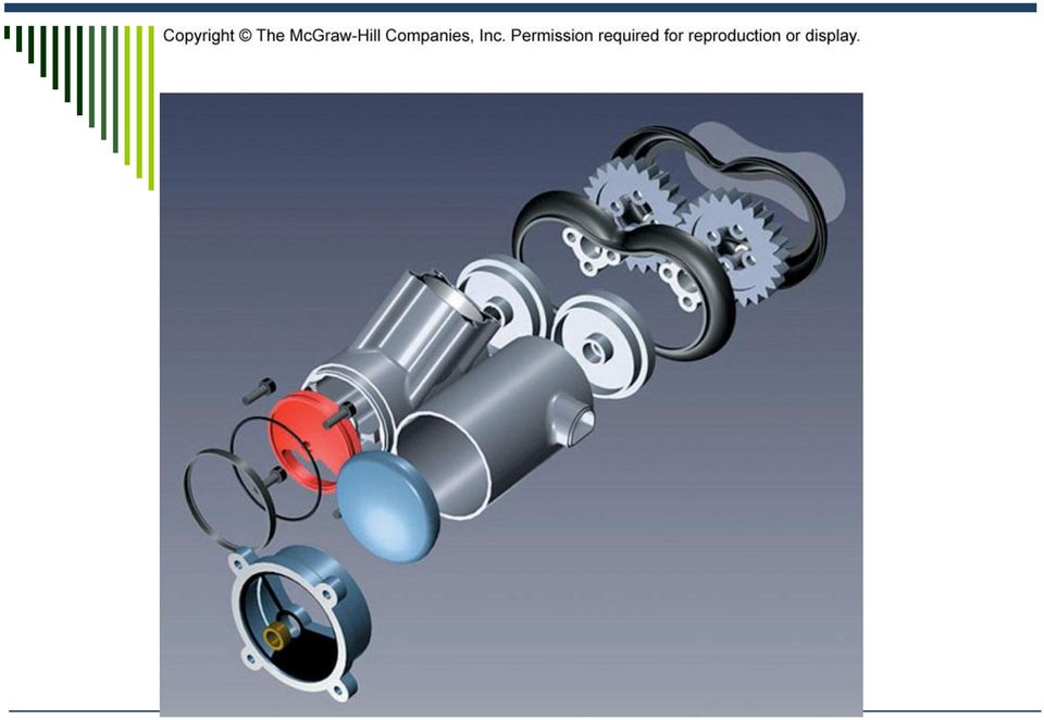
14 Assembly Drawings Types pictorial assembly gives a general graphic description of each part, and uses center lines to show how the parts are assembled.

15
16 Part and Drawing Numbers A part number is usually a string of numbers coded in such a way that a company can keep accurate records of its products. Drawing number: Each company develops its own standard numbering system, based on various criteria such as sequential numbers, combinations of numbers and letters, sheet sizes, number of parts in the assembly, model numbers, function, etc.

17 Title Blocks Title blocks are used to record all the important information necessary for the working drawings. The title block is normally located in the lower right corner of the drawing sheet. Title blocks should contain the following: Name and address of the company or design activity. Title of the drawing. Drawing number. Names and dates of the drafters, checker, issue date, contract number, etc.

18 Title Blocks Design approval, when subcontractors are used. Additional approval block. Predominant drawing scale. Federal supply code for manufacturers (FSCM) number. Drawing sheet size letter designation. Actual or estimated weight of the item. Sheet number, if there are multiple sheets in the set.

19

20 Parts Lists A complete set of working drawings must include a detailed parts list or bill of material. Based on ANSI standards, a parts list should be located in the lower right corner above the title block.

21 Parts Lists The information normally included in a parts list is as follows: Name of the part. A detail number for the part in the assembly. The part material, such as cast iron or bronze. The number of times that part is used in the assembly. The company-assigned part number. Other in formation, such as weight, stock size, etc.
22 Revision Blocks When a drawing is revised because of design changes, errors, etc., an accurate record of the change should be created. This information includes: the person making the change description of the change the change number approval for the change
23 Engineering Changes Order Used to make changes in a design. Most industries require the use of engineering change notice (ECN). Common features includes; Identification of what has to be changed in the form of part numbers, part names, and drawing numbers.
24 Engineering Changes Order An explanation of the need for the requested changed. A list of all documents and departments affected by the change. Approval by the projects managers Instruction describing when the changes are to be implemented.
25 Scale and Tolerance Specs. The designations METRIC or SI appear in or near the title block to show that metric dimensions and scale are used on the drawing. A graphics scale can also be used, especially on mapping drawings. Tolerances are specified in a drawing using toleranced dimensions. For those dimensions that are not specifically toleranced, a general tolerance note is used.
26 Zones and Tabular Drawing Zones are used on large sheets for reference purposes. Zones in engineering drawing are similar to the zones used on highway maps. Tabular drawings are used when several similar parts have common features. Such parts can be grouped together into a family of parts.
27 Working Assembly Drawing A working assembly drawing, also known as a detailed assembly, combines on a single sheet the detail drawing and the assembly drawing, usually a section view. Such drawings are used for relatively simple assemblies that use some standard parts.
28 Threaded Fastener Fastening is a method of connecting or joining two or more parts together, using processes or devices. One of the most common methods used for fastening is mechanical fastening, a process that uses manufactured devices such as screws, pins, or rivets to hold parts of an assembly together.
29 Thread Terminology Axis Chamfer Crest Depth Die External thread Internal thread Lead Major Diameter Minor Diameter Pitch Pitch diameter Root Screw thread Side Tap Thread: angle, form, series Thread per inch
30 Thread Specification English system Thread form - the profile or shape of a thread cut into a cylinder. Sharp-V American National Unified Unified National Round Metric Acme Square Knuckle Buttress
31 Thread Specification English system Series - the number of threads per inch for a given diameter. Coarse quick assembly or disassembly of cast iron, soft metals, and plastic. NC or UNC. Fine - fasteners are used when a great deal of force is necessary for assembly, and are designated NF or UNF. Extra fine - fasteners are used when the length of engagement is short and the application calls for high degrees of stress.
32 Thread Specification English system Class Class 1-a loose fit where quick assembly is required and looseness or play between parts is acceptable. Class 2-a high-quality, general purpose, commercial class of fit for bolts, nuts, and screws widely used in mass production. Class 3-a very high-quality threaded fastener with a close fit, used for precision tools and for high stress and vibration applications.
33 Threaded Specification English system Note Major diameter Number of threads Form Series Class Internal or external Qualifying information
34
35 Thread Specification Metric system A complete metric thread note should contain the following information, in the order given: Thread form symbol - The letter M is used to designate the metric profile. The J profile class is a modified M profile. Nominal size (basic major diameter) Pitch General purpose tolerance
36
37
38 Thread Drawings Three conventional methods: Detailed Schematics Simplified
39
40
41 Standard Bolts, Stud and Screw General types of standard threaded fastener: Bolt - a mechanical threaded device with a head on one end and threads on the other end. Bolts are paired with nuts. A nut is a mechanical threaded device used on the end of a bolt, a stud, or a machine screw. Stud - a rod that is threaded on both ends and joins two mating parts. A nut may be used on one end.
42 Standard Bolts, Stud and Screw Cap screw - a mechanical threaded device with a head on one end and threads on the other end. Cap screws join two mating parts and have longer threads than bolts. Machine screw - a mechanical threaded device with a head on one end and threads on the other end. The threaded end may screw into a mating part, or may be used with a nut.
43 Standard Bolts, Stud and Screw Set screw - a mechanical threaded device with or without a head, used to prevent rotation or movement between parts, such as a shaft and a collar.
44 Nonthreaded Fastener Nonthreaded fasteners are mechanical devices generally used to prevent motion between mating parts. Dowels Pins dowel, straight, tapered, groove Key plain, gib head, Woodruff, P&W Rivet Retaining rings
45 Springs Mechanical devices that expand or contract due to pressure or force. Compression Tension Extension Flat Constant force
46 Mechanism A machine is a combination of interrelated parts for using or applying energy to do work. Gears - transmit rotational power and motion between portions of a mechanism. Cams - used to translate rotational motion into linear motion. Linkages - the most common type of mechanism in use to transmit force. A linkage consists of a (usually) linear element, called the bar, and one or two joints.
47 Mechanism Bearings - used in conjunction with other mechanisms such as gears and linkages to minimize friction and wear between the parts. Plain Rolling contact
48
49
50 Welding Welding drawings are a specialized type of technical drawing which differs from many other types of drawings in that its main focus is to specify how parts are joined together. Since welds are both permanent and structural, proper location and orientation of the welded members and the type of weld used are important to properly specify.
51 Welding Eight basic parts; Reference line Leader line and arrow Basic weld symbol (location and depth of weld) Finish symbol Weld symbol (type of weld) Dimensions Supplementary symbols Tail and specifications
52
53
54 Reprographics Refers to the technology and techniques of reproducing documents. After the engineering drawings have been created they are copied for others to use, carefully stored, and set up for easy future accessibility. After the original drawing is created, it must be carefully stored or archived. The process used to store and retrieve engineering drawings is called archiving.
55 Reprographics Techniques Blueprinting Diazo Xerography Microfilming Digital Scanning Storage CAD
Screw Thread Design. Rev. 3-4-09
 Screw Thread Design Screw Thread Fundamentals A screw thread is defined as a ridge of uniform section in the form of a helix on either the external or internal surface of a cylinder. Internal threads refer
SCREW THREADS C H A P T E R 17
 C H A P T E R 17 SCREW THREADS Screw threads are of prime importance in machine drawing. It is a functional element used as temporary fasteners such as bolt, stud, nut and screw etc. These are constructed
DWG 001. Blueprint Reading. Line Standards Drawing Symbols. Instructor Guide
 DWG 001 Blueprint Reading Line Standards Drawing Symbols Instructor Guide Module Purpose Introduction The purpose of the Blueprint Reading modules is to introduce students to production drawings and blueprint
DESCRIPTION. Stud Bolts for Pressure-Temperature Piping 2-1. General Purpose End-to-End Studs 2-2. Tap End Stud Bolts 2-3. Double End Stud Bolts 2-4
 DESCRIPTION PAGE B7 Studs and Nuts Stud Bolts for Pressure-Temperature Piping 2-1 General Purpose End-to-End Studs 2-2 Tap End Stud Bolts 2-3 Double End Stud Bolts 2-4 Sigma Fasteners, Inc. Section 2 STUD
American National, Unified Screw Threads
 C h a p t e r 9 American National, Unified Screw Threads In this chapter, you will learn the following to World Class standards:! Why Use Fasteners! The Text Designation for the Unified National Thread!
MACHINE DRAWING QUESTION BANK. 2. What are the parts not usually sectioned? (Nov 04)
") MACHINE DRAWING QUESTION BANK UNIT-I 1. Answer the following: Sketch a i. Hexagonal nut convention, ii. Convention of a stud bolt. (Nov 04) 2. What are the parts not usually sectioned? (Nov 04) 3 Answer
MACHINE DRAWING QUESTION BANK UNIT-I 1. Answer the following: Sketch a i. Hexagonal nut convention, ii. Convention of a stud bolt. (Nov 04) 2. What are the parts not usually sectioned? (Nov 04) 3 Answer
Lathe Milling Attachment
 Lathe Milling Attachment By L C. MASON BY CLEVERLY stacking cold-rolled flat stock together, T-slots and slide for this lathe milling attachment are made without costly machinery. In fact, only two tools,
Fasteners and screw threads
 ISO Standards Handbook: Fasteners and screw threads Volume 2: Product standards Contents Part 3 : Product standards 2001, Ed. 5, 1094 p., ISBN 92-67-10345-8 3.1 External drive hexagon head bolts and screws
UNITED STATES CUTTING TOOL INSTITUTE Product Groupings for Standards Activities CUTTING TOOL PRODUCTS
 CUTTING TOOL PRODUCTS 1. BORING ISO 5609 Boring bars for indexable inserts Dimensions ISO 6261 Boring bars (tool holders with cylindrical shank) for indexable inserts Designation JIS B 4128 Boring bars
Lecture slides on rolling By: Dr H N Dhakal Lecturer in Mechanical and Marine Engineering, School of Engineering, University of Plymouth
 Lecture slides on rolling By: Dr H N Dhakal Lecturer in Mechanical and Marine Engineering, School of Engineering, University of Plymouth Bulk deformation forming (rolling) Rolling is the process of reducing
Section. Tolerances. Aluminum Extrusion Manual. 4th Edition
 Section 8 Tolerances Aluminum Extrusion Manual 4th Edition Section 8 How straight is straight enough? How flat is flat enough? How uniform must a wall thickness be in order to be acceptable? These are
This last dimension, the thread pitch diameter, is the most important as it is a reference from which all other thread measurements originate
 Training Objectives After watching the video and reviewing this printed material, the viewer will gain knowledge and understanding of the design and use of various thread types and how they are produced.
To Use any command in this guide: 1. Select the option from the Design Menu in the Mechanical Eng workspace.
 120 1 ME Mechanical Engineers use a variety of mechanical drawings and computer tools for analysis and design. During the design process, drawings are used throughout to develop and document the design
Metric System & Specifications
 Metric System & Specifications Throughout history, people have been trying to limit the number of measurement systems. Today, only two systems, inch-pound and metric, are predominate in most industrial
Removing chips is a method for producing plastic threads of small diameters and high batches, which cause frequent failures of thread punches.
 Plastic Threads Technical University of Gabrovo Yordanka Atanasova Threads in plastic products can be produced in three ways: a) by direct moulding with thread punch or die; b) by placing a threaded metal
Common Mechanical Engineering Terms
 Common Mechanical Engineering Terms Ball and Detent (n) A simple mechanical arrangement used to hold a moving part in a temporarily fixed position relative to another part. The ball slides within a bored
Introduction to JIGS AND FIXTURES
 Introduction to JIGS AND FIXTURES Introduction The successful running of any mass production depends upon the interchangeability to facilitate easy assembly and reduction of unit cost. Mass production
It's large enough to handle most welding job shop projects, yet small enough to make it a worth while home-workshop tool
 It's large enough to handle most welding job shop projects, yet small enough to make it a worth while home-workshop tool H Craft Print Project No. 272 ERE'S a metal bender that will enable you to bend
Product Design (Part 4)
") Product Design (Part 4) Engineering Drawing Chapter 16 Drawing Standards Line conventions and lettering- ANSI/ASME Y14.2M-1992 Multiview and sectional view drawings- ANSI/ASME Y14.3M-1994 Pictorial drawing-ansi/asme
Product Design (Part 4) Engineering Drawing Chapter 16 Drawing Standards Line conventions and lettering- ANSI/ASME Y14.2M-1992 Multiview and sectional view drawings- ANSI/ASME Y14.3M-1994 Pictorial drawing-ansi/asme
OWNER S/OPERATOR S - PARTS MANUAL CEMENT MIXER MODEL MX-80
 OWNER S/OPERATOR S - PARTS MANUAL CEMENT MIXER MODEL MX-80 Read the Operator s Manual entirely. When you see this symbol, be aware that the subsequent instructions and warnings are serious - follow without
CATIA Functional Tolerancing & Annotation TABLE OF CONTENTS
 TABLE OF CONTENTS Introduction...1 Functional Tolerancing and Annotation...2 Pull-down Menus...3 Insert...3 Functional Tolerancing and Annotation Workbench...4 Bottom Toolbar Changes...5 3D Grid Toolbar...5
Fastener Handout. Introduction: Engineering Design Representation 2. Threads 2. Local Notes (callouts) 8. Threaded Mechanical Fasteners 13
 8. Threaded Mechanical Fasteners 13") Fastener Handout Introduction: Engineering Design Representation 2 Threads 2 Effect of thread angle on strength: 3 Standardization of Threads: 4 Descriptions of the Thread Series: 4 Class fit: 5 Specification
Fastener Handout Introduction: Engineering Design Representation 2 Threads 2 Effect of thread angle on strength: 3 Standardization of Threads: 4 Descriptions of the Thread Series: 4 Class fit: 5 Specification
INSTRUCTION MANUAL AND PARTS LIST MODEL 14-10
 VERTICAL BAND SAWS INSTRUCTION MANUAL AND PARTS LIST MODEL 1-10 DAKE/PARMA WHEN ORDERING PARTS GIVE COMPLETE SERIAL NUMBER OF MACHINE GIVE PART NUMBER AND NAME GIVE AMOUNT REQUIRED Unless the above data
Suspension and Steering Systems Operation. The Steering/Suspension System (Overview)
") Suspension and Steering Systems Operation Below is an overview of the suspension and steering systems The Steering/Suspension System (Overview) "Suspension," when discussing cars, refers to the use of
Suspension and Steering Systems Operation Below is an overview of the suspension and steering systems The Steering/Suspension System (Overview) "Suspension," when discussing cars, refers to the use of
DRAFTING MANUAL. Gears (Bevel and Hypoid) Drafting Practice
 Drafting Practice") Page 1 1.0 General This section provides the basis for uniformity in engineering gears drawings and their technical data for gears with intersecting axes (bevel gears), and nonparallel, nonintersecting
Page 1 1.0 General This section provides the basis for uniformity in engineering gears drawings and their technical data for gears with intersecting axes (bevel gears), and nonparallel, nonintersecting
DRAFTING AND DESIGN. For additional program information see: http://www.hillcollege.edu/students/teched/drafting/.
 DRAFTING AND DESIGN For additional program information see: http://www.hillcollege.edu/students/teched/drafting/. Certificate of Completion in Basic Computer Aided Drafting Major Code: 6055 TSI (Testing)
Technical Data. 7. Bearing Fits. 7.1 Interference. 7.2 Calculation of interference F B LLLLLLLLL( A-54
 Technical Data 7. Bearing Fits 7.1 Interference For rolling s the rings are fixed on the or in the housing so that slip or movement does not occur between the mated surface during operation or under. This
B.TECH. (AEROSPACE ENGINEERING) PROGRAMME (BTAE) Term-End Examination December, 2011 BAS-010 : MACHINE DESIGN
 PROGRAMME (BTAE) Term-End Examination December, 2011 BAS-010 : MACHINE DESIGN") No. of Printed Pages : 7 BAS-01.0 B.TECH. (AEROSPACE ENGINEERING) PROGRAMME (BTAE) CV CA CV C:) O Term-End Examination December, 2011 BAS-010 : MACHINE DESIGN Time : 3 hours Maximum Marks : 70 Note : (1)
No. of Printed Pages : 7 BAS-01.0 B.TECH. (AEROSPACE ENGINEERING) PROGRAMME (BTAE) CV CA CV C:) O Term-End Examination December, 2011 BAS-010 : MACHINE DESIGN Time : 3 hours Maximum Marks : 70 Note : (1)
TRUSTED SOLUTIONS AND INNOVATION CATALOG DIE SETS
 www.danly.com TRUSTED SOLUTIONS AND INNOVATION CATALOG DIE SETS Quality & performance Quick delivery Precision Components www.danly.com CATALOG DIE SETS Service We Deliver and Quality You Can Depend On
CAM-03, Camshaft Assembly Oil Seal Replacement
 CAM-03, Camshaft Assembly Oil Seal Replacement Tools Jack stands Floor Jack Metric Socket set Metric Wrench set Porsche Timing Belt Tension tool (P9201) Flywheel Lock (P9206) Balance Shaft Pin Spanner
3000, 4000, 4100, 7500, 7700
 3000, 4000, 4100, 7500, 7700 Drum & Disc Brake Lathes s Identification READ these instructions before placing unit in service. KEEP these and other materials delivered with the unit in a binder near the
Machine Screws, Dowel Pins and Hardware
 Machine Screws, Dowel Pins and Section Contents Plain Socket Head Screws...Page 13-2 Wire Locking Screws...Page 13-3 Captive Screws...Page 13- Ventilation Screws...Page 13- Shoulder Screws...Page 13-
Thread and End Connection
 www.swagelok.com and End Connection Identification Guide 2 Contents Introduction and End Connection Terminology.. 4 General Terminology... 5 Step-by-Step Identification Procedure for s and End Connections...
Caps STANDARD WEIGHT Inches / Pounds
 Standard Caps you are here: Home > Weldbend Catalog > Fittings > Caps Caps STANDARD WEIGHT Inches / Pounds For Metric Units >Click Here Nominal Pipe Size Outside Inside Wall Thickness (T) Length (E) Pipe
STORAGE, INSTALLATION AND MAINTENANCE PROCEDURES
 GATE VALVE O.S. & Y 1.0 Periodic Inspections 1.1 The valve stem packing should be inspected at least monthly. If the stem packing shows signs of leakage, simply tighten the adjusting nuts to compress the
OD 1401 9 PRECISION MEASURING INSTRUMENTS
 SUBCOURSE EDITION OD 1401 9 PRECISION MEASURING INSTRUMENTS PRECISION MEASURING INSTRUMENTS SUBCOURSE OD1401 EDITION 9 Unites States Army Combined Arms Support Command Fort Lee, VA 23801-1809 5 CREDIT
For mechanical & hydraulic presses Inch & metric taps
 www.danly.com TRUSTED SOLUTIONS AND INNOVATION Professional IDT TM In-Die Tapping Catalog For mechanical & hydraulic presses Inch & metric taps www.danly.com Professional IDT TM In-Die Tapping Service
These features have made Lo Torc valves the choice of high pressure plug value users, worldwide:
 LO TORC Plug Valve The high value, dependable performance, and low maintenance requirements of Halliburton Lo Torc valves can help reduce overall operating costs and help cut downtime. These features have
DYNA RIDER FOOTBOARD KIT
 -J0 REV. 0-0-0 DYNA RIDER FOOTBOARD KIT GENERAL Kit Number 000 Models For model fitment information, see the P&A Retail Catalog or the Parts and Accessories section of www.harley-davidson.com (English
GEAROLOGY 4-1 WORMS AND WORM GEARS WORMS AND WORM GEARS
 GEAROLOGY 4-1 4 4-2 GEAROLOGY COMMON APPLICATIONS: Worm and worm gear sets are used in many, everyday products including: electrical mixers, hubometers, right Now that you have an understanding of two
MET 306. Activity 8a. Mechanism Design Creo 2.0 Level 7 POINT A GROUND LINK LINK 1 LINK 2 LINK 3 POINT B 10/15/2010 1
 Mechanism Design Creo 2.0 Level 7 POINT A LINK 1 GROUND LINK LINK 2 LINK 3 POINT B 10/15/2010 1 Download parts ground, key, link_1, link_2, link_3 and pulley from the V:/MET_306/Activity_8_Creo drive.
Introduction to Linear Actuators: Precision Linear Motion Accomplished Easily and Economically
 Introduction to Linear Actuators: Precision Linear Motion Accomplished Easily and Economically Part 1 of 2 When students are trained in classic mechanical engineering, they are taught to construct a system
Pole Lathe and Shave Horse Design
 Pole Lathe and Shave Horse Design These pictures and accompanying words are Copyright Michael Hughes February 2002. They are not to be re-produced, in part or whole, without permission from the author.
Two most common lock nut groups: 1-Prevailing Torque Type Lock Nuts:
 Two most common lock nut groups: 1. PREVAILING TORQUE a design feature of the lock nut produces friction between threads of mated components thereby increasing the force needed to tighten as well as loosen
Char-Lynn Spool Valve Hydraulic Motors. Repair Information. W Series Geroler Motors
 Char-Lynn Spool Valve Hydraulic Motors Repair Information W Series Geroler Motors with Parking Brake 004 Nut Key Ring, Retaining Bearing Ring, Retaining Ring, Retaining Washer (Thick), Pressure Washer,
The Keep It Simple, Steel (KISS) Standard
 Standard") The Keep It Simple, Steel (KISS) Standard A standard Electronic Data Interchange (EDI) format for the exchange of Bill of Material (BOM) information within the steel fabrication industry Updated in March
The Keep It Simple, Steel (KISS) Standard A standard Electronic Data Interchange (EDI) format for the exchange of Bill of Material (BOM) information within the steel fabrication industry Updated in March
CHAPTER 65 TAIL ROTOR DRIVE SYSTEM. Section Title Page
 CHAPTER 65 TAIL ROTOR DRIVE SYSTEM Section Title Page 65-00 Description........................................ 65.1 65-10 Tail Rotor Drive Fan Shaft.............................. 65.1 65-20 Tail Rotor
Chapter 2 Lead Screws
 Chapter 2 Lead Screws 2.1 Screw Threads The screw is the last machine to joint the ranks of the six fundamental simple machines. It has a history that stretches back to the ancient times. A very interesting
ASME Geometric Dimensioning and Tolerancing Professional Certification
 ASME Geometric Dimensioning and Tolerancing Professional Certification Applicant Information STATEMENT OF POLICY ON THE USE OF ASME GDTP SYMBOLS AND AUTHORIZATION IN ADVERTISING ASME has established procedures
Trunnion-Design Ball Valves
 Trunnion-Design Ball Valves 12" 20" (DN 300 500) Series 7150 12" (DN 300) Series 730S 12" 20" (DN 300 500) Series 7300 14" 24" (DN 350 600) Series 9150 14" 24" (DN 350 600) Series 9300 Installation, Maintenance
Mechanical Installation
 Page -1-1. INTRODUCTION AND PURPOSE 1.1. This specification covers the installation, testing and precommissioning of mechanical equipment. Work is to be performed in conjunction with the manufacturer s
Technical Product Specification (TPS)
") ISO Standards collection Technical Product Specification (TPS) Contents ISO 1:2002 Geometrical Product Specifications (GPS) -- Standard reference temperature for geometrical product specification and verification
ISO Standards collection Technical Product Specification (TPS) Contents ISO 1:2002 Geometrical Product Specifications (GPS) -- Standard reference temperature for geometrical product specification and verification
Fastener Handout. Introduction: Engineering Design Representation 2. Threads 2. Local Notes (callouts) 8. Threaded Mechanical Fasteners 13
 8. Threaded Mechanical Fasteners 13") Fastener Handout Introduction: Engineering Design Representation 2 Threads 2 Effect of thread angle on strength: 3 Standardization of Threads: 4 Descriptions of the Thread Series: 4 Class fit: 5 Specification
Fastener Handout Introduction: Engineering Design Representation 2 Threads 2 Effect of thread angle on strength: 3 Standardization of Threads: 4 Descriptions of the Thread Series: 4 Class fit: 5 Specification
Pipe Thread Types and Designations
 Pipe Thread Types and Designations Overview: Different types of screw threads have evolved for fastening, and hydraulic systems. Of special concern are plastic-to-metal, taper/parallel threaded joints
Fundamentals Engineering Drawing Practices
 ASME Y14.35M; Revision of Engineering Drawings and Associated Documents. This Standard defines the practices of revising drawings and associated documentation and establishes methods for identification
METAL-TURNING LATHE Built from Stock Parts
 by Frank Beatty USING STANDARD PARTS and stock materials that are available almost anywhere, you can build this metalworking lathe with only a few tools. Because of simplification of the assembly in order
1.8 CRANKSHAFT OIL SEALS
 SERIES 60 SERVICE MANUAL 1.8 CRANKSHAFT OIL SEALS An oil seal is fitted between each end of the crankshaft and the bores of the flywheel housing and gear case cover to retain the lubricating oil in the
Slide the new steering column shaft through the steering column from the driver compartment.
 Slide the new steering column shaft through the steering column from the driver compartment. Push the column shaft through the steering column until the machined end is out past the column lower bushing.
Rebuild Instructions for 70001 and 70010 Transmission
 Rebuild Instructions for 70001 and 70010 Transmission Brinn, Incorporated 1615 Tech Drive Bay City, MI 48706 Telephone 989.686.8920 Fax 989.686.6520 www.brinninc.com Notice Read all instructions before
PARTS MANUAL EH12-2 ENGINE. Model. PUB-EP5713 Rev. 7/99
 PARTS MANUAL Model EH12-2 ENGINE PUB-EP5713 Rev. 7/99 940 Lively Blvd. Wood Dale, IL 60191 Phone: 630-350-8200 Fax: 630-350-8212 e-mail: sales@robinamerica.com www.robinamerica.com Copyright 1999 Robin
FAG Hydraulic nuts. Technical Product Information
 FAG Hydraulic nuts Technical Product Information Contents Application 2 Design 2 Design variants 3 Pressure generators, connectors 4 Dimension tables for FAG hydraulic nuts (metric) 6 Dimension tables
SET-UP AND INSTALLATION FOR LEAD SCREW CARTRIDGE ASSEMBLY
 SET-UP AND INSTALLATION FOR LEAD SCREW CARTRIDGE ASSEMBLY 82-13-1 O-Ring (Rear) The Lead Screw Assembly is shipped separately. Note: Install Electrical and Pneumatic Circuitry. Be Sure electrical and pneumatic
Making 3D Threads in Feature Based Solid Modelers
 Making 3D Threads in Feature Based Solid Modelers THREAD BASICS Making true geometric threads in feature-based solid modelers is a fairly straightforward process and can be handled using several different
Selecting and Sizing Ball Screw Drives
 Selecting and Sizing Ball Screw Drives Jeff G. Johnson, Product Engineer Thomson Industries, Inc. Wood Dale, IL 540-633-3549 www.thomsonlinear.com Thomson@thomsonlinear.com Fig 1: Ball screw drive is a
NEW SIX-SEALS CUTTING RING. INTERNATIONAL INDUSTRIAL PATENT Nr. 864061 of the 10/03/99 FLANKS AND DOES NOT REPLACE THE STANDARD RING CURRENTLY IN USE
 B4 NEW SIX-SEALS CUTTING RING. INTERNATIONAL INDUSTRIAL PATENT Nr. 864061 of the 10/03/99 FLANKS AND DOES NOT REPLACE THE STANDARD RING CURRENTLY IN USE AVAILABLE IN CARBON AND STAINLESS STEEL 23 THEORY
Modeling Curved Surfaces
 Modeling Cylindrical and Curved Theory Views of Cylinders Contour Lines Extruded Surfaces Revolved Surfaces & Cutouts Profile Shape Axis of Revolution Swept Surfaces & Cutouts Profile Shape Path Curves
DRAFTING. Prepared by:
 GTRI MACHINE SERVICES DRAFTING STANDARDS Prepared by: Machine Services Department Georgia Tech Research Institute December 16, 2011 Copyright 2011 Georgia Tech Research Corporation. Alll rights reserved.
TIE ROD END DESIGN TUTORIAL
 TIE ROD END DESIGN TUTORIAL THE FOLLOWING IS A SIMPLIFIED STEP-BY-STEP GUIDE INTENDED TO ILLUSTRATE THE DECISIONS AND COMPROMISES INVOLVED IN DESIGNING A TIE ROD END. THE PROCESS FOR DESIGNING ANY BALL
3. Loosen 3 x grub screws in the Dec end cap and unscrew the cap and counterweight shaft. NEQ6 Belt Modification Kit.
 NEQ6 Belt Modification Kit. Thank you for your purchase. Please read these instructions fully before fitting. Your package should contain 2 off 47 & 2 off 12 tooth aluminium pulleys 2 off belts 6mm wide
Standards for Working Drawings
 Standards for Working Drawings 27 August 2013 Department of Mechanical and Mechatronic Engineering and Sustainable Manufacturing California State University, Chico Chico, California 95929-0789 Contents
ANSI APPROVED 04/11/2014 ANSI APPROVED 08/17/2011. 45 Reaffirmation ANSI APPROVED 02/28/2014. 45 Reaffirmation ANSI APPROVED 05/06/2013
 STANDARDS STATUS REPORT As of November 4, 2015 Note: Dates in RED indicate the last action taken; Highlighted Items Indicate New/Open Items; Grey items have been closed Document TC Status Comments ASME
Machine devices, jig devices
 Machine devices, jig devices 853 K0697 Rolled thread studs DIN 6379 Material: Tempered steel. KIPP Rolled thread studs DIN 6379 Order No. D L B1 B2 Approx. weight g Surface finish: Thread rolled. Class
Char-Lynn Hydraulic Motor. Repair Information. 10 000 Series. October, 1997
 Char-Lynn Hydraulic Motor October, 1997 Repair Information Geroler Motor Two Speed 001 27 Retainer inside bore of valve plate bearingless motors only 4 15 16 3 6 35 Parts Drawing 25 2 2 1 19 17 36 40 47
GEOMETRICAL AND MECHANICAL ENGINEERING DRAWING
 CARIBBEAN EXAMINATIONS COUNCIL REPORT ON CANDIDATES WORK IN THE CARIBBEAN ADVANCED PROFICIENCY EXAMINATION MAY/JUNE 2007 GEOMETRICAL AND MECHANICAL ENGINEERING DRAWING Copyright 2007 Caribbean Examinations
OHIO University Mechanical Engineering Summary Report: Human Power System for Small Appliances and Machinery
 OHIO University Mechanical Engineering Summary Report: Human Power System for Small Appliances and Machinery Appalachian Human Power Brad Bundy Ben Chovan Zach Fetchu Ed Passarrelli Ryan Tedford Will Zaylor
SECTION 2B WHEEL ALIGNMENT TABLE OF CONTENTS
 SECTION 2B WHEEL ALIGNMENT TABLE OF CONTENTS Description and Operation... 2B2 Four Wheel Alignment... 2B2 Toein... 2B2 Caster... 2B2 Camber... 2B2 Diagnostic Information and Procedures... 2B3 Tire Diagnosis...
Mould and Die Standard Parts
 Mould and Die Standard Parts Tampere University of technology - Tuula Höök Mould standard parts can be divided into the following groups: Standard mould set with guide bars, guide sleeves and other guiding
The word teamster today means a truck driver,
 Page 47 Heron of Alexandria The word teamster today means a truck driver, but originally it meant a wagon driver, someone who drives a team of horses, mules or oxen. Over 2000 years ago teamsters in the
SHOP NOTES METAL SHAPER FOR YOUR SHOP
 SHOP NOTES METAL SHAPER FOR YOUR SHOP A METAL SHAPER is indispensable for certain machining operations where flat surfaces must be produced within very close limits, such as machining flats on castings,
Introduction to Accuracy and Repeatability in Linear Motion Systems
 Introduction to accuracy and repeatability in linear motion systems By Gary Rosengren, Director of Engineering Tolomatic, Inc. About the Author Gary Rosengren is Director of Engineering at Tolomatic and
C O N V E Y O R C O M P O N E N T S C H A I N S B E L T S B E A R I N G S
 C O N V E Y O R C O M P O N E N T S C H A I N S B E L T S B E A R I N G S January 2009 Issue 6 Valu Guide Brackets The Ultimate in Adjustability and Cost Savings Valu Guide brackets are part of a family
Copper and Copper Alloy Tube, Pipe and Fittings
 Copper and Copper Alloy Tube, Pipe and Fittings COPPER and COPPER ALLOY TUBE and PIPE Seamless Copper Pipe: Copper pipe is almost pure copper manufactured to the requirements of ASTM B 42 - Standard Specification
Engineering & Design: Coordinate Dimensioning
 s e c t i o n Section Contents NADCA No. Format Page Frequently Asked Questions (FAQ) -2 1 Introduction -2 2 Section Objectives -3 3 Standard and Precision Tolerances -3 4 Production Part Technologies
Maxi-Stamper. 200 to 1,000 Tons STAMPING OUT DOWNTIME
 TM Maxi-Stamper 200 to 1,000 Tons STAMPING OUT DOWNTIME Standard Features Steel Fabricated Construction Drive Capacity Rated 1/2 Above Bottom of Stroke Self-Diagnostic Solid State Controller Moveable Operator
DECIPHERING WELD SYMBOLS
 DECIPHERING WELD SYMBOLS When welds are specified on engineering and fabrication drawings, a cryptic set of symbols issued as a sort of shorthand for describing the type of weld, its size, and other processing
Number Wheeler P/N Description Set Rex P/N Notes 1 603500 Base 1 J001 2 603501 Support, Right 1 J002 3 603502 Support, Left 1 J003 4 600328 Nut (M8)
") 1 603500 Base 1 J001 2 603501 Support, Right 1 J002 3 603502 Support, Left 1 J003 4 600328 Nut (M8) 4 5 600130 Spring Washer (8mm) 4 6 600344 Roll Pin (M6x30) 4 7 600129 Socket Hd Cap Screw (M8x25) 4 8
1 603500 Base 1 J001 2 603501 Support, Right 1 J002 3 603502 Support, Left 1 J003 4 600328 Nut (M8) 4 5 600130 Spring Washer (8mm) 4 6 600344 Roll Pin (M6x30) 4 7 600129 Socket Hd Cap Screw (M8x25) 4 8
7.3 Fit selection. Inner ring: Rotating. Outer ring: Stationary. Inner ring: Stationary. Outer ring: Rotating. Inner ring: Stationary
 7. Bearing Fits 7. Fitting For rolling s, inner and outer rings are fixed on the or in the housing so that relative movement does not occur between fitting surfaces during operation or under. This relative
16 April 2012 1032011-F 1994-2002 Dodge Adjustable Track bar with Relocation Bracket 1
 16 April 2012 1032011-F 1994-2002 Dodge Adjustable Track bar with Relocation Bracket 1 BD Adjustable Track Bar w/bracket Dodge 2500-3500 4WD Models 1994-2002 Dodge 1500 4WD Model 1994-2001 P/N# 1032011-F
INSTRUCTIONS FOR CHAIN LINK INSTALLATION Chain Link fence & Posts Meshdirect.co.uk
 INSTRUCTIONS FOR CHAIN LINK INSTALLATION Chain Link fence & Posts Meshdirect.co.uk This guide explains how to correctly install our chain link fencing and post system. The guide provides details of the
Round Housing with Side Ports
 Power Steering Steering Control Unit (SCU) Parts and Repair Information 5 Series Steering Control Units 001 Square Housing with Side Ports Round Housing with Side Ports T E L RP Round Housing with End
SAMPLE TEST PAPER - I
 SCHEME E SAMPLE TEST PAPER - I Course Name : Mechanical Engineering Group Course Code : AE/PG/PT/ME/MH/FE Semester : Third Subject : Mechanical Engineering Drawing 12042 Time : 90 Minutes Marks: 25 Instruction:
Ensat. Self-tapping inserts SOLID BODIES LINE
 Ensat Self-tapping inserts SOLID BODIES LINE Index DESCRIPTION Page Presentation 3 Materials and Applications 4 Features 5 Preparing the receiving hole 6 Tools Codes 7 Ensat Series 302 Ensat Series 303
Module 5 Couplings. Version 2 ME, IIT Kharagpur
 Module 5 Couplings Lesson 1 Introduction, types and uses Instructional Objectives At the end of this lesson, the students should have the knowledge of The function of couplings in machinery. Different
CATIA Drafting TABLE OF CONTENTS
 TABLE OF CONTENTS Introduction...1 Drafting...2 Drawing Screen...3 Pull-down Menus...4 File...4 Edit...5 View...6 Insert...7 Tools...8 Drafting Workbench...9 Views and Sheets...9 Dimensions and Annotations...10
TYPE E Main Valve Sizes 3 /8 through 12
 SD 3001F PRINTED IN U.S.A. SD 3001F/0707 A B TYPE E MAIN VALVE C D E TYPE E Main Valve Sizes 3 /8 through 12 The Spence Type E Main Valve is of normally closed, single seat design featuring packless construction,
UNIT II Robots Drive Systems and End Effectors Part-A Questions
 UNIT II Robots Drive Systems and End Effectors Part-A Questions 1. Define End effector. End effector is a device that is attached to the end of the wrist arm to perform specific task. 2. Give some examples
800-348-8467 www.fittingsunlimited.com
 Thread and Port Identification Guide 800-348-8467 www.fittingsunlimited.com INDEX Index... 1 Explanation of Symbols... 2 How to Measure Threads... 3-4 Metric vs English Threads... 5 North American Connections
Fisher 1052 Size 20 Diaphragm Rotary Actuator with F and G Mounting Adaptation
 Instruction Manual 1052 Size 20 Actuator (F & G) Fisher 1052 Size 20 Diaphragm Rotary Actuator with F and G Mounting Adaptation Contents Introduction... 1 Scope of manual... 1 Description... 1 Specifications...