Quantum Energy Generator
|
|
|
- Prudence Preston
- 10 years ago
- Views:
Transcription
1 Quantum Energy Generator VERSION: 1.02 LAST UPD: 4 JULY 2014 CONTACT: [email protected]

 Organization, which they open sourced on their website. To learn more about the QEG, please visit: http://www.fixtheworldproject.")
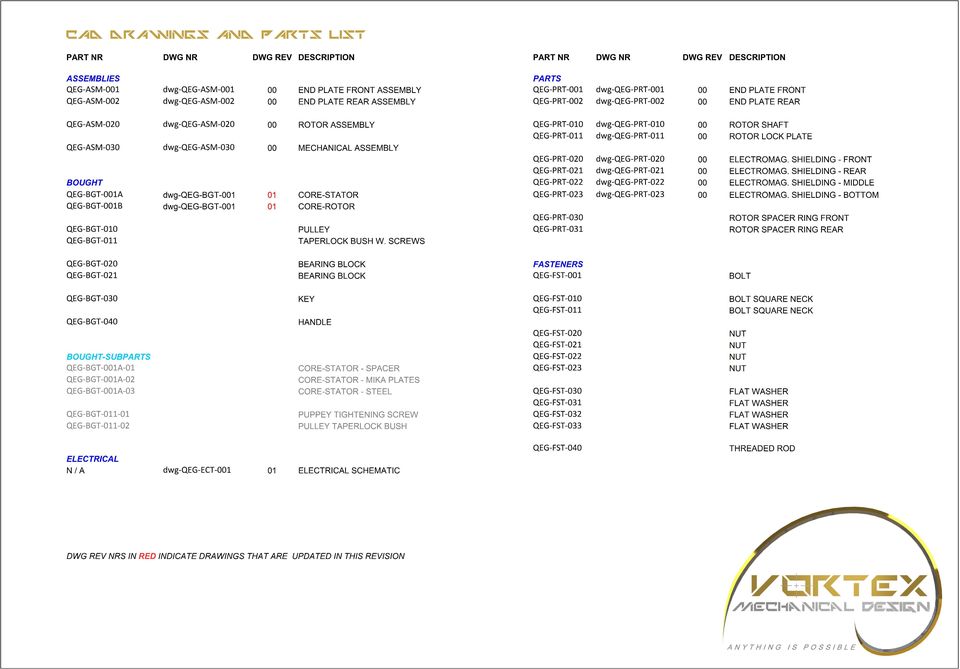
2 Introduction: This document contains the manufacturing drawings for the QEG: Quantum Energy Generator. The design is based on the blueprints from the Fix the World (FTW) Organization, which they open sourced on their website. To learn more about the QEG, please visit: Following their example, I also made this document containing the drawings freely available on my company's website: my own involvement: During the interview with FTW by alternative energy reporter Sterling Allan, James Robitaille from FTW told that he had about 9kW of equipment running (as a load) on his prototype QEG with less than 1 kw of input: Initially my business partners and I planned to order components and build one ourselves. However, when FTW released a well documented test report with energy input and output measurements from a new prototype they built in Morocco, we pulled the handbrake. The measurements showed that no more than 590W of usable output was achieved with an input of 607W: Although the report also stated that this Morocco prototype was not tuned/optimized yet, a new test report showing similar results as mentioned in the Sterling Allan interview has not yet been released. Until such a new report is available, we decided to wait with ordering any components. Why the FTW team was not able to reproduce similar results with their Morocco prototype as they achieved with their first one, remains an unanswered question for me. Thanks: Specifically I want to thank the FTW team for all their efforts and countless hours they spent on researching and sharing their findings. Thanks guys, you're an example. QEG related links: FTW Hope Girl blog Hope Girl Youtube QEG forum Sterling Allan / Peswiki n%27s_quantum_energy_generator Partners in this project: Eric Nuver, Electrical Engineer Kees van der Koppel, Inventor Van Der Koppel Bedrijven Why this document: I made this document with the following intentions: -make the QEG more compatible with metric dimensions/parts -make a solid connection between the rotor and the shaft (instead of using Loctite) -make the rotor retained in the QEG assembly (by spacer rings) instead of being dependent on eccentric locks on the bearings (which are hard to access) for its correct positioning -make a full set of (mechanical) drawings freely available, so that anybody can give them to a local machine shop and thus making it easier to build a QEG Future Scope: Once FTW releases a new test reports which show the results we're after, my team and I will order parts and start building. At that point my intention is to supplement this document with more drawings and documents like: -complete system drawing, including all the electrical components and mounting frame -full part/supplier list, also for electrical components, including lead times and prices -drawing set for imperial dimensioning/parts -any other relevant documents Contact: Most pencils still need erasers, at least my one does now and then, so your feedback on this document is welcome as long as it is constructive. Also for inquiries regarding collaboration and/or if you need any professional 2D/3D CAD services, you can contact me at: Name: Website: Linkedin: Rodolphe Reuchlin, BSc. Mechanical Engineer [email protected]


3
4 ITEM NO. QTY. PART NR DWG NR DESCRIPTION SPECIFICATION SUPPLIER 1 1 QEG-PRT-1 dwg-qeg-prt-1 END PLATE FRONT MERREM-MATERIALS.COM 2 1 QEG-BGT-020 BEARING BLOCK SBPF 204 AANDRIJFSHOP.NL / PEHAVO.NL 3 3 QEG-FST-010 BOLT SQUARE NECK M8x30MM CLASS 8.8 FABORY.NL / PEHAVO.NL 4 3 QEG-FST-021 NUT M8 CLASS 8.8 FABORY.NL / PEHAVO.NL 5 3 QEG-FST-031 FLAT WASHER M8 FABORY.NL / PEHAVO.NL REVISIONS REV. DESCRIPTION ORIGINAL ISSUE CONSIDER USING LOCTITE 243 THREADLOCKER DUE TO FIBRATIONS IN QEG ISO EXPLODED VIEW SIDE VIEW 4 FRONT VIEW END PLATE FRONT ASSEMBLY QEG DWG NR: dwg-qeg-asm-1 QEG-ASM-1 DO NOT SCALE DRAWING SCALE: 1:4 SHEET 1 OF 1

5 ITEM NO. QTY. PART NR DWG NR DESCRIPTION SPECIFICATION SUPPLIER 1 1 QEG-PRT-2 dwg-qeg-prt-2 END PLATE REAR MERREM-MATERIALS.COM 2 1 QEG-BGT-021 BEARING BLOCK SBPF 206 AANDRIJFSHOP.NL / PEHAVO.NL 3 3 QEG-FST-011 BOLT SQUARE NECK M10x40MM CLASS 8.8 FABORY.NL / PEHAVO.NL 4 3 QEG-FST-022 NUT M10 CLASS 8.8 FABORY.NL / PEHAVO.NL 5 3 QEG-FST-032 FLAT WASHER M10 FABORY.NL / PEHAVO.NL REVISIONS REV. DESCRIPTION ORIGINAL ISSUE CONSIDER USING LOCTITE 243 THREADLOCKER DUE TO FIBRATIONS IN QEG ISO EXPLODED VIEW 4 4 SIDE VIEW FRONT VIEW END PLATE REAR ASSEMBLY QEG DWG NR: dwg-qeg-asm-2 QEG-ASM-2 DO NOT SCALE DRAWING SCALE: 1:4 SHEET 1 OF 1

6 ITEM NO. QTY. PART NR DWG NR DESCRIPTION SPECIFICATION SUPPLIER 1 1 QEG-BGT-1B dwg-qeg-bgt-1 CORE-ROTOR TORELCO.COM 2 1 QEG-PRT-010 dwg-qeg-prt-010 ROTOR SHAFT TORELCO.COM 3 1 QEG-PRT-011 dwg-qeg-prt-011 ROTOR LOCK PLATE MERREM-MATERIALS.COM REVISIONS REV. DESCRIPTION ORIGINAL ISSUE 4 2 QEG-FST-1 BOLT 0.25"x4.25" GRADE 5 FABORY.NL / PEHAVO.NL 5 2 QEG-FST-020 NUT 0.25" GRADE 5 FABORY.NL / PEHAVO.NL 6 1 QEG-FST-023 NUT M22x1 CLASS 8.8 FABORY.NL / PEHAVO.NL 7 4 QEG-FST-030 FLAT WASHER 0.25" FABORY.NL / PEHAVO.NL 8 1 QEG-FST-033 FLAT WASHER M22 FABORY.NL / PEHAVO.NL A CONSIDER USING LOCTITE 243 THREADLOCKER DUE TO FIBRATIONS IN QEG A 5 SECTION A-A SIDE VIEW 8 ISO EXPLODED VIEW 6 ROTOR ASSEMBLY DWG NR: QEG dwg-qeg-asm-020 QEG-ASM-020 DO NOT SCALE DRAWING SCALE: 1:2 SHEET 1 OF 1

7 REVISIONS REV. DESCRIPTION ORIGINAL ISSUE CUT HOLES TO SUIT IN END PLATE FOR COIL WIRES OF CORE 1 ISO EXPLODED VIEW CONSIDER USING LOCTITE 243 THREADLOCKER DUE TO FIBRATIONS IN QEG CONSIDER USING LOCTITE 243 THREADLOCKER ON SET SCREWS DUE TO FIBRATIONS IN QEG NOTE: 14 CONSIDER USING LOCTITE 243 THREADLOCKER ON SET SCREWS DUE TO FIBRATIONS IN QEG -FASTEN ELECTROMAGNETIC SHIELDS TO SUIT, E.G. SELF TAPPING SCREWS -HANDLES (QEG-BGT-40) ARE OPTIONAL DRILL HOLES AND FASTEN TO SUIT MECHANICAL ASSEMBLY QEG DWG NR: dwg-qeg-asm-030 QEG-ASM-030 DO NOT SCALE DRAWING SCALE: NTS SHEET 1 OF 4

8 APPROX APPROX. 7.6 REVISIONS REV. DESCRIPTION 44.5 B A ORIGINAL ISSUE DETAIL Q SCALE 1 : 1 DETAIL P SCALE 1 : Q P B SECTION A-A 4 A SECTION B-B MECHANICAL ASSEMBLY QEG DWG NR: dwg-qeg-asm-030 QEG-ASM-030 DO NOT SCALE DRAWING SCALE: NTS SHEET 2 OF 4

9 ITEM NO. QTY. PART NR DWG NR DESCRIPTION SPECIFICATION SUPPLIER 1 1 QEG-BGT-1A dwg-qeg-bgt-1 CORE-STATOR TORELCO.COM REVISIONS REV. DESCRIPTION ORIGINAL ISSUE 1 QEG-BGT-1A QEG-BGT-1A-02 8 QEG-BGT-1A QEG-ASM-1 dwg-qeg-asm-1 END PLATE FRONT ASSEMBLY 1 QEG-PRT-1 dwg-qeg-prt-1 END PLATE FRONT MERREM-MATERIALS.COM 1 QEG-BGT-020 BEARING BLOCK SBPF 204 AANDRIJFSHOP.NL / PEHAVO.NL 3 QEG-FST-010 BOLT SQUARE NECK M8x30MM CLASS 8.8 FABORY.NL / PEHAVO.NL 3 QEG-FST-031 FLAT WASHER M8 FABORY.NL / PEHAVO.NL 3 QEG-FST-021 NUT M8 CLASS 8.8 FABORY.NL / PEHAVO.NL 3 1 QEG-ASM-2 dwg-qeg-asm-2 END PLATE REAR ASSEMBLY 1 QEG-PRT-2 dwg-qeg-prt-2 END PLATE REAR MERREM-MATERIALS.COM 1 QEG-BGT-021 BEARING BLOCK SBPF 206 AANDRIJFSHOP.NL / PEHAVO.NL 3 QEG-FST-011 BOLT SQUARE NECK M10x40MM CLASS 8.8 FABORY.NL / PEHAVO.NL 3 QEG-FST-032 FLAT WASHER M10 FABORY.NL / PEHAVO.NL 3 QEG-FST-022 NUT M10 CLASS 8.8 FABORY.NL / PEHAVO.NL BILL OF MATERIALS (BOM ) EXPLANATION: THIS BOM IS A SO CALLED "INDENTED" BOM. THIS MEANS THAT ONLY TOP LEVEL PART NRS HAVE AN ITEM NR (BALLOON NR). IN CASE THIS TOP LEVEL PART NR CONSISTS OF SUB-PARTS/SUB-ASSEMBLIES, THESE PARTS NRS ARE LISTED UNDERNEATH THE TOP LEVEL PART NR. FOR EXAMPLE ITEM NR 1 (PART NR QEG-BGT-1A) IS AN ASSEMBLY THAT CONSISTS OF PART NRS. -QEG-BGT-1A-01 -QEG-BGT-1A-02 -QEG-BGT-1A-03 THE SECOND PART OF THIS BOM IS ON THE NEXT PAGE PART NR NAMING CONVENTION: -QEG-ASM-XXX = ASSEMBLY -QEG-PRT-XXX = PART (MACHINED/MANUFACTURED) -QEG-BGT-XXX = BOUGHT PAR OR ASSEMBLY -QEG-FST-XXX = FASTENER MECHANICAL ASSEMBLY QEG DWG NR: dwg-qeg-asm-030 QEG-ASM-030 DO NOT SCALE DRAWING SCALE: NTS SHEET 3 OF 4

10 ITEM NO. QTY. PART NR DWG NR DESCRIPTION SPECIFICATION SUPPLIER 4 1 QEG-ASM-020 dwg-qeg-asm-020 ROTOR ASSEMBLY 1 QEG-BGT-1B dwg-qeg-bgt-1 CORE-ROTOR TORELCO.COM 1 QEG-PRT-010 dwg-qeg-prt-010 ROTOR SHAFT TORELCO.COM 1 QEG-PRT-011 dwg-qeg-prt-011 ROTOR LOCK PLATE MERREM-MATERIALS.COM REVISIONS REV. DESCRIPTION ORIGINAL ISSUE 2 QEG-FST-1 BOLT 0.25"x4.25" GRADE 5 FABORY.NL / PEHAVO.NL 2 QEG-FST-020 NUT 0.25" GRADE 5 FABORY.NL / PEHAVO.NL 4 QEG-FST-030 FLAT WASHER 0.25" FABORY.NL / PEHAVO.NL 1 QEG-FST-023 NUT M22x1 CLASS 8.8 FABORY.NL / PEHAVO.NL 1 QEG-FST-033 FLAT WASHER M22 FABORY.NL / PEHAVO.NL 5 1 QEG-PRT-020 dwg-qeg-prt-020 ELECTROMAG. SHIELDING - FRONT PERFORATED 30% OPENING 6 1 QEG-PRT-021 dwg-qeg-prt-021 ELECTROMAG. SHIELDING - REAR PERFORATED 30% OPENING 7 1 QEG-PRT-022 dwg-qeg-prt QEG-PRT-023 dwg-qeg-prt-023 ELECTROMAG. SHIELDING - MIDDLE ELECTROMAG. SHIELDING - BOTTOM 9 1 QEG-PRT-030 CUT TO SUIT ROTOR SPACER RING FRONT 10 1 QEG-PRT-031 CUT TO SUIT ROTOR SPACER RING REAR PERFORATED 30% OPENING PERFORATED 30% OPENING 11 1 QEG-BGT-010 PULLEY SPA 71-1 GROOVE AANDRIJFSHOP.NL / PEHAVO.NL 12 1 QEG-BGT-011 TAPERLOCK BUSH W. SCREWS BUSH MM SHAFT AANDRIJFSHOP.NL / PEHAVO.NL 1 QEG-BGT QEG-BGT QEG-BGT-030 KEY DIN 6885A, 6x6x30 FABORY.NL / PEHAVO.NL 14 4 QEG-BGT-040 HANDLE (OPTIONAL) QEG-FST-020 NUT 0.25" GRADE 5 FABORY.NL / PEHAVO.NL QEG-FST-030 FLAT WASHER 0.25" FABORY.NL / PEHAVO.NL 17 8 QEG-FST-040 THREADED ROD 0.25"x9" GRADE B7 FABORY.NL / PEHAVO.NL NOTE: THIS BOM IS A SO CALLED "INDENTED" BOM. SEE PREVIOUS PAGE FOR EXPLANATION THE FIRST PART OF THIS BOM IS ON THE PREVIOUS PAGE PART NR NAMING CONVENTION: -QEG-ASM-XXX = ASSEMBLY -QEG-PRT-XXX = PART (MACHINED/MANUFACTURED) -QEG-BGT-XXX = BOUGHT PAR OR ASSEMBLY -QEG-FST-XXX = FASTENER MECHANICAL ASSEMBLY QEG DWG NR: dwg-qeg-asm-030 QEG-ASM-030 DO NOT SCALE DRAWING SCALE: NTS SHEET 4 OF 4

11 REVISIONS 15.0 REV. DESCRIPTION ORIGINAL ISSUE ±0.1 x8 REAM TO SIZE 01 MATERIAL CORRECTION: 25 GAUGE --> 24 GAUGE x x x ± ±0.05 REAM TO SIZE x TIG WELD ON OD OF ROTOR CORE-ROTOR dwg-qeg-bgt-1 4x TIG WELD ON OD OF STATOR NOTE: CORE-STATOR dwg-qeg-bgt-1 -DIMENSIONING ACCORDING TO FIX THE WORLD PDF, 25 MARCH 2014, DRAWING # ALL DIMENSIONS ARE IN INCHES -TOTAL LAMINATION THICKNESS = 3.5" +/ " (= +/-1 LAMINATION THICKNESS) M19C5, 24 Gauge CORE-STATOR AND CORE-ROTOR DIMS AS PER FTW QEG DWG NR: dwg-qeg-bgt-1 QEG-BGT-1A / QEG-BGT-1B DO NOT SCALE DRAWING SCALE: 1:2 SHEET 1 OF 1 01

12 REV. REVISIONS DESCRIPTION ORIGINAL ISSUE BRIDGE RECTIFIER ADDED FOR DRIVE MOTOR LINE N NEUTRAL 120V VARIAC FOR SPEED ADJUSTMENT DRIVE MOTOR 120V L1 BRIDGE RECTIFIER ARMATURE FUSE OUTPUT 230V / 240V, 42A 10kW +/- 4Hz LINE FUSE NOTE: L2 PRIMARY CIRCUIT COILS: 2x 350T, #10 AWG HPT / HAPT CAPACITORS: 12x 2.5uF, 20V (=0.208uF, 24kV) TUNE FOR RESONANCE -THIS CIRCUIT IS A MODIFIED VERSION OF THE "QEG SCHEMATIC" THAT CAN BE FOUND ON PAGE 7 OF THE ORIGINAL FIX THE WORLD PDF ON 25 MARCH 2014 DRIVE MOTOR 180V ARMATURE, VARIABLE SPEED DC, PERMANENT MAGNETS, 25 RPM EXCITER CIRCUIT -SPARK GAP: BETWEEN 0.5" " -CAPACITORS: 2x 15pF, 3150V PARALELL (=30pF, 3150V) -COIL: 1T, #1AWG HAPT WIRE, (451uH, 1.3MHz) NEUTRAL LINE DPDT SWITCH (DOUBLE POLE, DOUBLE TRHOW) -PRIMARY CIRCUIT THE ABOVE MENTIONED "QEG SCHEMATIC" ORIGINALY MENTIONED HERE 12x 1.5uF OR 0.1uF CAPACITORS. THE 12x 2.5uF CAPACITORS IN THIS DRAWING COME FROM THE "PARTS LIST" ON PAGE 8 AND FROM THE PARAGRAPH "CAPACITORS" ON PAGE 15 OF THE SAME DOCUMENT. SECUNDARY CIRCUIT COILS: 2x 31T, #20 AWG HTAIHSD 240V LINE IN -EXCITER CIRCUIT THE ABOVE MENTIONED "QEG SCHEMATIC" ORIGINALY MENTIONED HERE ONE 33pF CAPACITOR. THE 2x 15pF CAPACITORS IN THIS DRAWING COME FROM THE "PARTS LIST" ON PAGE 8 OF THE SAME DOCUMENT. IN PARALELL THEY YIELD 30pF. RR JULY 2014 ELECTRICAL SCHEMATIC QEG DWG NR: dwg-qeg-elc-1 DO NOT SCALE DRAWING SCALE: NTS SHEET 1 OF 1 01

13 REVISIONS REV. DESCRIPTION R2 ORIGINAL ISSUE PCD PCD P ISO VIEW x x8 x x3 PCD SIDE VIEW DETAIL P 4 FRONT VIEW POM C / DELRIN END PLATE FRONT DWG NR: QEG dwg-qeg-prt-1 QEG-PRT-1 DO NOT SCALE DRAWING SCALE: 1:2 SHEET 1 OF 1

14 REVISIONS REV. DESCRIPTION R2 ORIGINAL ISSUE PCD PCD ISO VIEW 4 P x x8 x x3 PCD SIDE VIEW FRONT VIEW DETAIL P POM C / DELRIN END PLATE REAR DWG NR: QEG dwg-qeg-prt-2 QEG-PRT-2 DO NOT SCALE DRAWING SCALE: 1:2 SHEET 1 OF 1

15 REVISIONS REV. DESCRIPTION ORIGINAL ISSUE ISO VIEW X 45 A A 88 ± A - B B B 42 1 X SECTION A-A 30 h A R h M22x1 B h8-0 0 SECTION B-B 6 N DIN C45 / AISI 1045 ROTOR SHAFT DWG NR: QEG dwg-qeg-prt-010 QEG-PRT-010 DO NOT SCALE DRAWING SCALE: 1:1 SHEET 1 OF 1

16 REVISIONS REV. DESCRIPTION ORIGINAL ISSUE ISO VIEW R ± R2 R FRONT VIEW SIDE VIEW POM C / DELRIN ROTOR LOCK PLATE QEG DWG NR: dwg-qeg-prt-011 QEG-PRT-011 DO NOT SCALE DRAWING SCALE: 1:1 SHEET 1 OF 1

17 REVISIONS REV. DESCRIPTION ORIGINAL ISSUE R2 PCD X8 PCD ISO VIEW 4 P 90 NOTE: -THICKNESS 1MM -PERFORATED 30% OPENING R FRONT VIEW DETAIL P SCALE 1 : 1 STEEL / ZINC PLATED / GALVANIZED ELECTROMAG. SHIELDING - FRONT QEG DWG NR: dwg-qeg-prt-020 QEG-PRT-020 DO NOT SCALE DRAWING SCALE: 1:2 SHEET 1 OF 1

18 REVISIONS REV. DESCRIPTION ORIGINAL ISSUE R2 PCD x8 PCD x3 PCD ISO VIEW NOTE: 10 -THICKNESS 1MM -PERFORATED 30% OPENING FRONT VIEW STEEL / ZINC PLATED / GALVANIZED ELECTROMAG. SHIELDING - REAR QEG DWG NR: dwg-qeg-prt-021 QEG-PRT-021 DO NOT SCALE DRAWING SCALE: 1:2 SHEET 1 OF 1

19 REVISIONS REV. DESCRIPTION ORIGINAL ISSUE R201 ISO VIEW FRONT VIEW SIDE VIEW NOTE: -THICKNESS 1MM -PERFORATED 30% OPENING STEEL / ZINC PLATED / GALVANIZED ELECTROMAG. SHIELDING - MIDDLE QEG DWG NR: dwg-qeg-prt-022 QEG-PRT-022 DO NOT SCALE DRAWING SCALE: 1:4 SHEET 1 OF 1


20 REVISIONS REV. DESCRIPTION ORIGINAL ISSUE ISO VIEW 4 NOTE: -THICKNESS 1MM -PERFORATED 30% OPENING BOTTOM VIEW STEEL / ZINC PLATED / GALVANIZED ELECTROMAG. SHIELDING - BOTTOM QEG DWG NR: dwg-qeg-prt-023 QEG-PRT-023 DO NOT SCALE DRAWING SCALE: 1:2 SHEET 1 OF 1

TRANS-05, Torque Tube Removal, Rebuilding, and Installation
 TRANS-05, Torque Tube Removal, Rebuilding, and Installation Tools Metric Wrench Set Metric Socket Set Jack Stands (6 minimum) Floor Jack 8mm Cheesehead socket (also referred to as 12 point internal socket
MUSTANG II IFS COMPLETE PARTS PACKAGE
 MUSTANG II IFS COMPLETE PARTS PACKAGE Your Southern Rods & Parts Mustang II IFS Parts Package contains the following items: 1 pr) Upper Control Arms (2023) 1) Upper Arm Bolt Kit (MP-001-A) 1 pr) Lower
TECHNICAL INFORMATION
 TECHNICAL INFORMATION Models No. 2012NB Description 304mm (12") Automatic Thickness Planer CONCEPTION AND MAIN APPLICATIONS * Compact and light weight (27 Kg./59 lbs) automatic thickness planer for easier
POWER WAVE 455M/STT & (CE)
") Illustration of Sub Assemblies Illustration of Sub Assemblies Illustration of Sub Assemblies Illustration of Sub Assemblies P-450 P-450 PARTS LIST FOR POWER WAVE 455M/STT & (CE) P-450-A P-450-A ILLUSTRATION
Illustration of Sub Assemblies Illustration of Sub Assemblies Illustration of Sub Assemblies Illustration of Sub Assemblies P-450 P-450 PARTS LIST FOR POWER WAVE 455M/STT & (CE) P-450-A P-450-A ILLUSTRATION
Permanent Magnetic Generator Construction Manual
 Permanent Magnetic Generator Construction Manual http://hojomotor.com Our Team Doing an On-site Assembly in Peru http://hojomotor.com Section 1) Introduction This manual describes how to build a 'permanent
Vehicle Design Summit Electric Hub Motor (V2) Eric Conner Harvey Tang Matthew Peddie
 Eric Conner Harvey Tang Matthew Peddie") Vehicle Design Summit Electric Hub Motor (V2) Eric Conner Harvey Tang Matthew Peddie Motivation The AHPV from VDS 1.0 used an expensive, NGM electric hub motor, costing roughly $8000. (picture on right)
Vehicle Design Summit Electric Hub Motor (V2) Eric Conner Harvey Tang Matthew Peddie Motivation The AHPV from VDS 1.0 used an expensive, NGM electric hub motor, costing roughly $8000. (picture on right)
FLOORTEC R 680 B. Part List US-English. Model: FLOORTEC R 680 B
 Model: Part List US-English Table of Contents General view 3 Rotomolded assembly 5 Chassis assembly 7 Drive assembly 9 Steering assembly 11 Control pedals assembly 13 Waste container assembly 15 Filter
ASSEMBLY DIAGRAM AND ASSEMBLY REFERENCE ULTIMA OLD SCHOOL 2 EVO & TC BELT DRIVE UNITS
 ASSEMBLY DIAGRAM AND ASSEMBLY REFERENCE ULTIMA OLD SCHOOL 2 EVO & TC BELT DRIVE UNITS BELT DRIVE ASSEMBLIES Part# 58-850 2 Old School Belt Drive Assembly - Polished Part# 58-851 2 Old School Belt Drive
Spare Parts List M96A.24SM/B M96A.28SM/B
 *16202390* 162.0239.0 REV5 14/04 2015 Spare Parts List M96A.24SM/B M96A.28SM/B Issue Table description Issue n. of pages Overall view 09/2008 1 C.h. return group and d.h.w. heat exchanger 09/2008 1 C.h.
Section M POWER LIFTS
 Section M POWER LIFTS December 2009 1M Index 1. 53-520244-000 Poly V Idler Assembly 2. 53-520205-000 N.A. Mounting Bracket 3. 53-520212-000 Cable Assembly 4. 53-600149-000 Wire Harness Assembly 5. 53-860322-010
PSS10H/B PSS12H/A ILLUSTRATED PARTS LISTS
 PSS10H/B PSS12H/A ILLUSTRATED PARTS LISTS AC AND DC GENERATOR SCHEMATIC ENGINE GENERATOR ASSEMBLY REF Description QTY PSS10 PSS12 1 Engine, Honda GX620K1VXC2 Code 637220 1 99779-000 GX670VXC2 Code 637220
PROFESSIONAL PRODUCTS- PET NAIL GROOMERS
 - S SERVICE NUMBER 29-0A/-0B 29-0E 29-0F 29-0H 29-0J 29-0K 29-0 To select the model desired, click on the highlighted service number. D-5 S LIST NEW MODEL(S) ADDED FIRST ISSUE 6/76, COLUMN # FIRST ISSUE
Flextec 450 PARTS LIST FOR RETURN TO MAIN INDEX
 Illustration of Sub Assemblies Illustration of Sub Assemblies Illustration of Sub Assemblies Illustration of Sub Assemblies P-652 RETURN TO MAIN INDEX PARTS LIST FOR Flextec 450 P-652 P-652-A P-652-A ILLUSTRATION
Number Wheeler P/N Description Set Rex P/N Notes 1 603500 Base 1 J001 2 603501 Support, Right 1 J002 3 603502 Support, Left 1 J003 4 600328 Nut (M8)
") 1 603500 Base 1 J001 2 603501 Support, Right 1 J002 3 603502 Support, Left 1 J003 4 600328 Nut (M8) 4 5 600130 Spring Washer (8mm) 4 6 600344 Roll Pin (M6x30) 4 7 600129 Socket Hd Cap Screw (M8x25) 4 8
1 603500 Base 1 J001 2 603501 Support, Right 1 J002 3 603502 Support, Left 1 J003 4 600328 Nut (M8) 4 5 600130 Spring Washer (8mm) 4 6 600344 Roll Pin (M6x30) 4 7 600129 Socket Hd Cap Screw (M8x25) 4 8
Single-Phase AC Synchronous Generator
 ST Series Single-Phase AC Synchronous Generator Instructions for Operation and Maintenance English to English translation by R.G. Keen, May 2004. ST Series of Single-Phase AC Synchronous Generators Description
3.0 CHARACTERISTICS. AR Auxiliary Relay High Speed, High Threshold 41-759.3C
 41-759.3C the magnetic core upon energizing of the switch. When the switch closes, the moving contacts bridge two stationary contacts, completing the trip circuit. Also during this operation two fingers
 UFO 1 FOLDER INDEX A2 FOLDING MACHINE TYPE 10060 LIST NO DESCRIPTION PAGE 10101M Main Assembly - Mechanical 2 10201M Main Roller Assembly 4 16101M Upper & Lower Perforator Shaft Assembly 6 12701M Primary
Understanding the Alternator
 http://www.autoshop101.com THIS AUTOMOTIVE SERIES ON ALTERNATORS HAS BEEN DEVELOPED BY KEVIN R. SULLIVAN PROFESSOR OF AUTOMOTIVE TECHNOLOGY AT SKYLINE COLLEGE SAN BRUNO, CALIFORNIA ALL RIGHTS RESERVED
DB 18 & DB 18E Options
 DB 8 & DB 8E Options Assembly Manual Boom Truss Element Truss 6m Passive Inventory check DB 8 & DB 8 E Boom Truss Kit 7-004-0 QTY Part # Description 6 60-0045 /6 wire clips 4 60-0048 /6 Thimble 4 60-0044
INSTALLATION AND OPERATING INSTRUCTIONS For Model GL1 Gate Locks
 Securitron Magnalock Corp. www.securitron.com ASSA ABLOY, the global leader Tel 800.624.5625 [email protected] in door opening solutions INSTALLATION AND OPERATING INSTRUCTIONS For Model GL1 Gate
Machine Screws, Dowel Pins and Hardware
 Machine Screws, Dowel Pins and Section Contents Plain Socket Head Screws...Page 13-2 Wire Locking Screws...Page 13-3 Captive Screws...Page 13- Ventilation Screws...Page 13- Shoulder Screws...Page 13-
1. Lay out 2 pieces of 7/8" tubing and mark for bending as shown. Remember that the bend is in the shaded area as shown below in Figure 1.
 MINI BIKE PLANS Page 1 INTRODUCTION Before starting to build your Mini-Bike, be sure that you have all the parts shown on the material list. You will note that tubing has been used in the construction.
Standard Bills of Materials Commonly Ordered Models Only
 Standard Bills of Materials Commonly Ordered Models Only Meters Always check www.lcmeter.com for the most current BOM. This document is for reference only. Always use Bill of Material shipped with meter
Electrically Released Brake ER-825, ER-1225 with Pin Drive Armatues for Montgomery Kone
 P-230 819-0466 Electrically Released Brake ER-825, ER-1225 with Pin Drive Armatues for Montgomery Kone Installation & Operating Instructions Contents Introduction........................... 3 Installation
Series 30000 Hose Reels
 Operating Instructions and Parts List for Series 30000 Hose Reels - MANUAL DRIVEN - - POWER DRIVEN - SAFETY PRECAUTIONS Personal injury and/or equipment damage may result if proper safety precautions are
Working Drawing and Assemblies. Chapter 10
 Working Drawing and Assemblies Chapter 10 Objectives 1.Define working drawings. 2. Describe how working drawings are used in industry. 3. List the major components of a complete set of working drawings.
Spare Parts List Activ A 25C Activ A 30C Activ A 35C Activ A 18S Activ A 25S Activ A 30S
 *1756202470* 17562.0247.0 REV3 06/09 2012 Spare Parts List Activ A 25C Activ A 30C Activ A 35C Activ A 18S Activ A 25S Activ A 30S Issue Table description Issue n. of pages Overall view 06/2009 1 C.h.
Slide the new steering column shaft through the steering column from the driver compartment.
 Slide the new steering column shaft through the steering column from the driver compartment. Push the column shaft through the steering column until the machined end is out past the column lower bushing.
ALBINS SEQUENTIAL SHIFTER
 ALBINS SEQUENTIAL SHIFTER Updated 12/11/11 8-AGB5-INST GENERAL NOTES The Albins Sequential Shifter is specifically designed for AGB transaxles. It features an integral reverse lockout lever and has a position
PRS X-axis E-chain installation: For tools with a 12 Z-Axis
 PRS X-axis Energy Chain (Echain) Installation Page -1- PRS X-axis E-chain installation: For tools with a 12 Z-Axis This kit is compatible with PRS Shopbots that have an X-axis cutting area of 96 to 144.
CFF-1 Follow Focus One C1241-0001
 CFF-1 Follow Focus One C1241-0001 Original Instructions: English Publication No. C1241-0001-800/1 Copyright 2011 All rights reserved throughout the world. No part of this document may be stored in a retrieval
TC 170 & TC 170 PD TRANSFER CASE
 Automotive Corporation TC 170 & TC 170 PD TRANSFER CASE PARTS MANUAL Fabco Automotive Corporation, Livermore, CA Ph:(925) 454-9500 Fax:(925) 454-9501 1-(800) 967-8838 www.fabcoautomotive.com VII. PARTS
Power Cube Open Source Ecology Page 1. Power Cube. Version 4
 Power Cube Open Source Ecology Page 1 Power Cube Version 4 Power Cube Open Source Ecology Page 2 Contents Table of Contents Power Cube... 1 Contents...2 Introduction... 3 Bill Of Materials...4 Discrete
ST Style Generator. Owners/Operators Manual
 ST Style Generator Owners/Operators Manual LLC 216 Airport Rd NE Milledgeville, GA 31061 478-453-9358-Office 478-457-5524- Tom Cell 478-251-2914- Chris Cell Table of Contents Page 2. Table of Contents
James M. Pleasants Company
 James M. Pleasants Company SUBMITTAL DATA GAINESVILLE MECHANICAL DECEMBER 20, 2013 PROJECT: GSU: J-183 HUMANITIES LAW BLDG. QUOTE NO:12116 ENGINEER: STEVENS & WILKINSON GASKETED PLATE HEAT EXCHANGER Tag:
PRODUCT MANUAL - M090
 PRODUCT MANUAL - M090 MODEL 203/266 ELECTRIC CAN OPENER 1 SAFETY CAUTION: SEVERED CAN LIDS HAVE CUTTING EDGES. USE OF A PROTECTIVE GLOVE OR TONGS IS ADVISED WHEN HANDLING LIDS. WARNING To avoid risk of
Allen-Bradley 1397 400-600HP AC Line Filter Kit
 Installation Instructions IN Allen-Bradley 1397 400-600HP AC Line Filter Kit Cat. Nos. 1397-LF600 What This Option Provides What This Kit Contains This option is intended to be applied when the primary
16 April 2012 1032011-F 1994-2002 Dodge Adjustable Track bar with Relocation Bracket 1
 16 April 2012 1032011-F 1994-2002 Dodge Adjustable Track bar with Relocation Bracket 1 BD Adjustable Track Bar w/bracket Dodge 2500-3500 4WD Models 1994-2002 Dodge 1500 4WD Model 1994-2001 P/N# 1032011-F
12-Volt Negative Ground Installation Instructions
 12-Volt Negative Ground Installation Instructions For Part Number: 1141, 1164, 1165, 1181 CAUTION!!! Before installing, please read the following important information... 1. The Ignitor is designed for
Elo Touch Solutions Wall-mounting Kit for the 5501L IDS Touchmonitors
 Installation Manual Elo Touch Solutions Wall-mounting Kit for the 5501L IDS Touchmonitors SW602206 Rev B Table of Contents Chapter 1: Safety Warning... 3 Chapter 2: Kit Contents... 4 Included in Kit...
VT SERIES. Owners Manual VARIABLE TRAVEL MOUNTAIN BIKE
 VT SERIES Owners Manual VARIABLE TRAVEL MOUNTAIN BIKE Multi purpose, Enduro, Trail ride, Light Freeride mountain bike Single pivot, linkage operated rear shock rear suspension Manitou Swinger SPV Air rear
MARK-3 DIS Digital Ignition Solution
 Overview: MARK-3 DIS Digital Ignition Solution WATERAX offers a conversion kit Digital Ignition Solution (DIS) for users that want to convert a MARK-3 from breaker points and mechanical cut-out switch
6 inch A-Arm Lift Kit WARNING: 16-018/16-019. installation instructions. will fit CLUB CAR DS. included:
 Revised May 205 6-08/6-09 6 inch A-Arm Lift Kit will fit CLUB CAR DS installation instructions included: Rear Lift Blocks Main Suspension Assembly Spindles A-Arms Rear Shock Mounting Plates U-Bolts WARNING:
KTZ32.2-51. data sheet parts list exploded view dimensional drawing sectional drawing performance curve. parts list as Excel-spreadsheet
 KTZ32.2-5 data sheet parts list exploded view dimensional drawing sectional drawing performance curve parts list as Excel-spreadsheet Heltorfer Str.6 40472 Düsseldorf Germany Tel.: +49-2-479373 Fax: +49-2-479429
Electric chain hoists LIFTKET
 Electric chain hoists LIFTKET 1 Spare part list AA AB Description of spare part Page Lifting gear section 01: hoist body 4 Version 1-1.3 5 Version 2-4.2 6 Version 5-7.2 7 Version 8.1-9.1 8 Version 1AK-5.1AK
ABB ! CAUTION. Type COQ Negative Sequence Generator Relay. (50/60 Hertz) 41-161J. Instruction Leaflet
 41-161J. Instruction Leaflet") ABB Instruction Leaflet 41-161J Effective: May 1997 Supersedes I.L. 41-161H Dated July 1984 ( ) Denotes Change Since Previous Issue Type COQ Negative Sequence Generator Relay (50/60 Hertz)! CAUTION Before
ABB Instruction Leaflet 41-161J Effective: May 1997 Supersedes I.L. 41-161H Dated July 1984 ( ) Denotes Change Since Previous Issue Type COQ Negative Sequence Generator Relay (50/60 Hertz)! CAUTION Before
CLASS III TRUCK PARTS Baker
 CLASS III TRUCK PARTS Baker Identify replacement parts for Baker PAL, PAL-AR, PAL-WR 7.2 Instant Access to 250,000 Parts and Growing Baker PAL, PAL-AR, PAL-WR 1 000 774-1033 Toggle 26 000 757-1050 Tie
SE-1200-EI. Operation & Parts Manual
 SE-1200-EI Operation & Parts Manual SE 1200 EI OWNERS MANUAL Table of Contents 1. Installation guide 2. Set-up instructions 3. Operation instructions 4. Cleaning 5. Troubleshooting 6. Parts manual 7. Electrical
Rebuild Instructions for 70001 and 70010 Transmission
 Rebuild Instructions for 70001 and 70010 Transmission Brinn, Incorporated 1615 Tech Drive Bay City, MI 48706 Telephone 989.686.8920 Fax 989.686.6520 www.brinninc.com Notice Read all instructions before
Air Vantage 500 Kubota
 Illustration of Sub Assemblies Illustration of Sub Assemblies Illustration of Sub Assemblies Illustration of Sub Assemblies P-625 P-625 RETURN TO MAIN INDEX PARTS LIST FOR Air Vantage 500 Kubota P-625-A
SINGLE CYLINDER BALANCE BEAM STEAM ENGINE WITH CYLINDRICAL VALVE. DESIGNED BY Mr. J.A.M. DE WAAL PAPAPKURA, NEW ZEALAND
 THIS DRAWING REMAINS THE PROPERTY OF J.A.M.DE WAAL, BRIGHTWELL STREET PAPAKURA 1 NEW ZEALAND (09)91 SINGLE CYLINDER BALANCE BEAM STEAM ENGINE WITH CYLINDRICAL VALVE DESIGNED BY Mr. PAPAPKURA, NEW ZEALAND
DESIGN AND DEVELOPMENT OF A QUOTING SYSTEM FOR A FASTENER MANUFACTURER
 19 th International Conference on Production research DESIGN AND DEVELOPMENT OF A QUOTING SYSTEM FOR A FASTENER MANUFACTURER E. Shayan, V. Chitroda Faculty of Engineering and Industrial Siences Swinburne
Armature Actuated Brakes
 Armature Actuated s P/N 8-078-890-05 effective 05/02/14 Installation and Service Instructions Series AAB Armature Actuated s Sizes 72 through 170 Model Numbers 33[ ]-1, 33[ ]-2, 33[ ]-3, 33[ ]-4, 33[ ]-5
VCE VET ENGINEERING STUDIES
 Victorian Certificate of Education 2013 SUPERVISOR TO ATTACH PROCESSING LABEL HERE STUDENT NUMBER Letter Figures Words VCE VET ENGINEERING STUDIES Written examination Section Wednesday 20 November 2013
4BT A/C Bracket Directions
 4BT A/C Bracket Directions This kit will be broken into smaller kits for ease of installation and recognition of hardware. Tools needed for install; 3/8 Ratchet 1/2 wrench 1/2 socket 9/16 wrench 9/16 socket
EZ-Steer Assisted Steering System
 EZ-Steer Assisted Steering System Installation Instructions Platform Kit P/N 53059-54 Case IH CVX 1135 CVX 1145 CVX 1155 CVX 1170 CVX 1190 CVX 1195 CVX 135 CVX 145 CVX 155 CVX 175 CVX 195 New Holland TVT
QR12 (1.22 ) Diameter Optical Encoder
 Diameter Optical Encoder") Improving the Quality of Life through the Power in Light QPhase QR12 (1.22 ) Diameter Optical Encoder Design Features: Low profile assembled height of Bearing design simplifies encoder attachment Resolutions
Improving the Quality of Life through the Power in Light QPhase QR12 (1.22 ) Diameter Optical Encoder Design Features: Low profile assembled height of Bearing design simplifies encoder attachment Resolutions
Power Window/Power Lock Installation. To begin with you will need all the parts listed below:
 Power Window/Power Lock Installation To begin with you will need all the parts listed below: From Donor Fiero: Fiero power window regulators Power window motors (Generic GM type part) -motors are riveted
TABLE OF CONTENTS DT7K INSTRUCTION MANUAL TABLE OF CONTENTS 1-19-00E DT7K
 TABLE OF CONTENTS DT7K INSTRUCTION MANUAL SECTION 100 DESCRIPTION & SPECIFICATIONS 17459 INSTALLATION DIMENSIONS - DT7K 17384 MOUNTING HOLE TEMPLATE S14930 INSTALLATION DRAWING - 14930 MOUNTING PEDESTAL
1/29/2008 DR70. Baja Motorsports Inc. P.O. Box 61150 Phoenix, AZ 85082 Toll Free: 888-863-2252 PART NUMBERS PRICES ARE SUBJECT TO CHANGE 1 of 43
 DR70 Toll Free: 888-863-2252 PART NUMBERS PRICES ARE SUBJECT TO CHANGE 1 of 43 CYLINDER & CYLINDER HEAD 1 DR70-001 883099044472 CYLINDER 1 1 2 DR70-002 883099044489 GASKET, CYLINDER 1 1 3 DR70-003 883099044496
Installation Manual. SKU# 21000 series (Base Rails) SKU# 22000 series (Overhead Racks)
 SKU# 22000 series (Overhead Racks)") Installation Manual SKU# 21000 series (Base Rails) SKU# 22000 series (Overhead Racks) Welcome to the world of TracRac! We re delighted that you have chosen TracRac, the ultimate sliding truck rack system.
Installation Manual SKU# 21000 series (Base Rails) SKU# 22000 series (Overhead Racks) Welcome to the world of TracRac! We re delighted that you have chosen TracRac, the ultimate sliding truck rack system.
- CONSTRUCTIONS 300 SECTIONAL VIEW 300 MECHANICAL SEAL 301 - DIMENSIONS AND WEIGHT 400 PUMP 400 PACKING 401
 CONTENTS Page - SPECIFICATIONS 200 SELECTION CHART 201 TYPE KEY AND CURVE SPECIFICATIONS 202 PERFORMANCE CURVE 70 204 PERFORMANCE CURVE 90 205 PERFORMANCE CURVE 120 206 PERFORMANCE CURVE 200 207 - CONSTRUCTIONS
RADIO AGE. The Newsletter of the Mid-Atlantic Antique Radio Club. Atwater Kent Variometers, Variocouplers, and Related Devices
 RADIO AGE The Newsletter of the Mid-Atlantic Antique Radio Club Volume 30 December 2005 Number 12 Atwater Kent Variometers, Variocouplers, and Related Devices BY RAY THOMPSON AND LEIGH BASSETT 2005, RAY
POWERS Controls No. 4 Pneumatic Damper Actuator
 POWERS Controls No. 4 Pneumatic Damper Actuator Technical Instructions Document No. 155-032P25 AP 331-2 Actuator Assembly 331-2929 Typical Actuator Assembly 331-2904 Typical Actuator Assembly 331-3000
*ADVANCED ELECTRIC GENERATOR & CONTROL FOR HIGH SPEED MICRO/MINI TURBINE BASED POWER SYSTEMS
 *ADVANCED ELECTRIC GENERATOR & CONTROL FOR HIGH SPEED MICRO/MINI TURBINE BASED POWER SYSTEMS Jay Vaidya, President Electrodynamics Associates, Inc. 409 Eastbridge Drive, Oviedo, FL 32765 and Earl Gregory,
Permanent Magnet Motor Kit, Magnetic Reed Type. (SKY-ReedMotorKit) Instructions
 Instructions") Permanent Magnet Motor Kit, Magnetic Reed Type (SKY-ReedMotorKit) Instructions This kit contains powerful permanent magnets. Exercise caution when handling them as they can pull on iron tools and snap
Permanent Magnet Motor Kit, Magnetic Reed Type (SKY-ReedMotorKit) Instructions This kit contains powerful permanent magnets. Exercise caution when handling them as they can pull on iron tools and snap
TS93 EMR T/PT/TDE. Surface applied door closer
 TS EMR T/PT/TDE Surface applied door closer Installation instructions: Pull side track mount door closer with smoke detector (EMR T) Push side track mount door closer with smoke detector (EMR PT) Double
SE-900-MP ECO -SERIES. Operation & Parts Manual
 SE-900-MP ECO -SERIES Operation & Parts Manual SE 900 MP ECO - SERIES OWNERS MANUAL Table of Contents 1. Installation guide 2. Set-up instructions 3. Operation instructions 4. Cleaning 5. Troubleshooting
STEADYfast Stabilizer Installation Notes Fifth Wheel and Travel Trailers 11/23/13
 STEADYfast Stabilizer Installation Notes Fifth Wheel and Travel Trailers 11/23/13 (See Supplemental Instructions for trailers with heavy duty round footplates and/or Power Leveling Systems) PHONE SUPPORT
Nuffield and Middleweight Leyland Tractor - 11 inch - Double Clutch Overhaul Part 1 - Clutch Removal and Dismantling
 Nuffield and Middleweight Leyland Tractor - 11 inch - Double Clutch Overhaul Part 1 - Clutch Removal and Dismantling Due to the many different configurations of cabed and non-cabed tractors this article
VOYAGER 570G. 744A Sprayer Control
 VOYAGER 570G 744A Sprayer Control U S E R M A N U A L U S E R M A N U A L Table of Contents CHAPTER 1 - INTRODUCTION...1 SYSTEM CONFIGURATIONS...1 KIT CONTENTS...3 CONTROL HOUSING ASSEMBLY...5 CHAPTER
Housing diameter Shaft diameter 1. Flange (Mounting of housing) Protection class shaft input (EN 60529) Protection class housing (EN 60529)
 Protection class shaft input (EN 60529) Protection class housing (EN 60529)") Direct mounting without coupling Flexible hollow shaft design up to diameter 4 mm Through hollow shaft or as end shaft (blind shaft) Easy installation by means of clamping shaft or blind shaft Short overall
Direct mounting without coupling Flexible hollow shaft design up to diameter 4 mm Through hollow shaft or as end shaft (blind shaft) Easy installation by means of clamping shaft or blind shaft Short overall
Go-kart for little race-drivers
 Go-kart for little race-drivers Drill and drive. Go-kart What it lacks in speed, it more than makes up for in fun: the go-kart will excite little race-drivers. 1 Introduction It s only a go-kart, but it
NATIONAL TYPE MB-40SL MULTI-BAND TANK 9/29/1953
 NATIONAL TYPE MB-40SL MULTI-BAND TANK 9/29/1953 1. GENERAL The MB-40SL tanks is intended for use in grid circuits with approximately 20 Watts input and in final plate tank circuits of transmitters when
Description. Dimensions. Features. www.pwb-encoders.com. precision works better
 Description The MEC22 is a high resolution optical hollow shaft encoder that can be fixed quickly and easily on different sizes of motor shafts. The encoder provides two square wave outputs in quadrature
Preview of Period 16: Motors and Generators
 Preview of Period 16: Motors and Generators 16.1 DC Electric Motors What causes the rotor of a motor to spin? 16.2 Simple DC Motors What causes a changing magnetic field in the simple coil motor? 16.3
Number Wheeler P/N Description Set Rex P/N Notes
 1 607051 Base 1 A050 2 607052 Motor Cover 1 A052 3 600778 Socket Hd Cap Screw (M8x60) 2 4 607053 Scrap Receiver 1 A053 5 607054 Tank Upper Cover 1 A054 6 607055 Oil Pot 1 A055 7 607056 Strainer 1 A056
Type: DILM115(RAC240) Article No.: 239548 Sales text Contactor,55kW/400V,AC operated. Ordering information
 Article No.: 239548 Sales text Contactor,55kW/400V,AC operated. Ordering information") Type: DILM115(RAC240) Article No.: 239548 Sales text Contactor,55kW/400V,AC operated Ordering information Connection technique Description Description Rated operational current Screw terminals 3 pole AC
Type: DILM115(RAC240) Article No.: 239548 Sales text Contactor,55kW/400V,AC operated Ordering information Connection technique Description Description Rated operational current Screw terminals 3 pole AC
Nordson Automatic Spray Gun Support Kits
 Nordson Automatic Spray Gun Support Kits Customer Product Manual Issued / For parts and technical support, call the Finishing Customer Support Center at (800) -99. This document is subject to change without
R O A D M A S T E R, I N C.
 R O A D M A S T E R, I N C. ROADMASTER, Inc. 6110 NE 127th Ave. Vancouver, WA 98682 6 13 11 MOUNTING BRACKET KIT Cable Tab 14 12 7 15 9 Cable Tab 360-896-0407 fax 360-735-9300 www.roadmasterinc.com ITEM
Type K current limiting fuse canister Technical information and installation guide
 Transformer components Type K current limiting fuse canister Technical information and installation guide The Type K current limiting fuse canister provides an air-insulated receptacle for general-purpose
SERVICE MANUAL. Corpus 3G. Seat system for electric wheelchair
 SERVICE MANUAL US Corpus 3G Seat system for electric wheelchair How to contact Permobil Head Office of the Permobil group Produced and published by Permobil AB, Sweden Version 4, 2014-07 Item No.: 205260-US-0
BR150 Pmi Baja Reaction 150cc Go Kart (VIN PREFIX L4VM)
") Page 1 of 21 Product Information Baja Web > Product Information > Parts Lists > GOKART > BR150 Pmi Baja Reaction 150cc Go Kart (VIN PREFIX L4VM) BR150 Pmi Baja Reaction 150cc Go Kart (VIN PREFIX L4VM)
Page 1 of 21 Product Information Baja Web > Product Information > Parts Lists > GOKART > BR150 Pmi Baja Reaction 150cc Go Kart (VIN PREFIX L4VM) BR150 Pmi Baja Reaction 150cc Go Kart (VIN PREFIX L4VM)
MGB Chrome Bumper Conversion
 MGB Chrome Bumper Conversion Installation Instructions For 1974 1/2-1980 MGB This kit requires cutting, welding, and painting. Professional installation recommended. Note: Every MGB body is slightly different
Boiler Plan II Table of Contents
 Cover Page Table Of Contents Introduction Parts List Additional Materials Assembly instructions Drawings 1-15 Boiler Plan II Table of Contents Introduction This will be a very rewarding project, if you
Range Road RR Series Semi-Automatic Firewood Processor. Crated Unit Assembly Manual
 Range Road RR Series Semi-Automatic Firewood Processor Crated Unit Assembly Manual 1 1) Undo 8-18mm x 19mm Nuts and bolts, 2 on each leg of top frame 2) Lift top of Metal crate off and move out of work
Chief S21M PARTS MANUAL. 2005 Chief Automotive Technologies
 Chief SM 00 Chief Automotive Technologies Chief s Limited One-Year Warranty & Liability CHIEF'S LIMITED ONE-YEAR WARRANTY & LIABILITY Chief Automotive Technologies, Inc. warrants for one year from date
CETAC Z-Drive Assembly
 CETAC Z-Drive Assembly Replacement Guide Manual Part Number 610144 Rev 1, 2012 CETAC Technologies, Printed in USA Overview This guide describes the necessary steps to replace the Z-drive assembly on your
9,000lb capacity 4 Post Lift Installation Manual
 9,000lb capacity 4 Post Lift Installation Manual Parts Checklist 1 Main side track with 9/16 hole on cylinder end complete with cylinder, hose and connector 1 Offside track 2 Cross Rails pre-assembled
TRS 090/105 Compressor. Repair Procedures
 TRS 090/105 Compressor Repair Procedures GENERAL FGG All repair and service operations should be performed on a clean bench and with the use of clean tools. Use genuine parts and correct tools for all
INSTALLATION OF A BAY WINDOW
 INSTALLATION OF A BAY WINDOW Installation of a Bay Window These instructions relate to the replacement of an existing bay window or replacement of a straight window with a new bay window, in an opening
Workholding systems. Magnetic clamping plates M-TECS SP 50 M-TECS SP 70
 Workholding systems Magnetic clamping plates M-TECS SP 50 M-TECS SP 70 12/2010 M-TECS SP Magnetic clamping system M-TECS square poles for extremely heavy machining M-TECS square poles on a vertical machining
CDX. EBARA PUMPS EUROPE S.p.A. CENTRIFUGAL PUMPS. Page - CONTENTS 100
 CONTENTS Page - CONTENTS 100 - SPECIFICATIONS 200 SELECTION CHARTS 201 PERFORMANCE CHART 70 202 PERFORMANCE CHART 90 203 PERFORMANCE CHART 120 204 PERFORMANCE CHART 200 205 - CONSTRUCTIONS 300 SECTIONAL
Model RC Armature-Slot- Insulation Folder
 Model RC Armature-Slot- Insulation Folder 21 Model RC will handle insulation material up to 8 wide between its guides. Creasing rollers are adjustable sideways to make troughs up to 6 wide. A fixed ruler-guide
Machine devices, jig devices
 Machine devices, jig devices 853 K0697 Rolled thread studs DIN 6379 Material: Tempered steel. KIPP Rolled thread studs DIN 6379 Order No. D L B1 B2 Approx. weight g Surface finish: Thread rolled. Class
DYNA RIDER FOOTBOARD KIT
 -J0 REV. 0-0-0 DYNA RIDER FOOTBOARD KIT GENERAL Kit Number 000 Models For model fitment information, see the P&A Retail Catalog or the Parts and Accessories section of www.harley-davidson.com (English
2&3 SECTION LOFT LADDER
 TWIST CATCH ASSEMBLY A4 A2 A1 A3 A7 A6 A5 2&3 SECTION LOFT LADDER Images feature the 3 section loft ladder, but the same instructions apply to both 2 & 3 section ladders Installation and Operating Instructions
Ensat. Self-tapping inserts SOLID BODIES LINE
 Ensat Self-tapping inserts SOLID BODIES LINE Index DESCRIPTION Page Presentation 3 Materials and Applications 4 Features 5 Preparing the receiving hole 6 Tools Codes 7 Ensat Series 302 Ensat Series 303
ALLDATA Online - 2006 Dodge Truck RAM 2500 Truck 2WD L6-5.9L DSL Turbo VI... Service and Repair
 Page 1 of 15 Home Account Contact ALLDATA Log Out Help PAUL REDEHOFT Select Vehicle New TSBs Technician's Reference Component Search: OK 2006 Dodge Truck RAM 2500 Truck 2WD L6-5.9L DSL Turbo VIN C Conversion
SERVICE PARTS LIST PAGE 1 OF 6 BASE ASSEMBLY SPECIFY CATALOG NO. AND SERIAL NO. WHEN ORDERING PARTS 12" DUAL BEVEL COMPOUND MITER SAW B27A
 PAGE 1 OF 6 BASE ASSEMBLY 00 0 EXAMPLE: Component Parts (Small #) Are Included When Ordering The Assembly (Large #). SPECIFY CATALOG NO. AND NO. WHEN ORDERING PARTS 1 02-80-0050 Thrust Bearing (1) 2 05-80-0510