Contents. Turning. A. General turning
|
|
|
- Annabel Rebecca Cole
- 9 years ago
- Views:
Transcription
1 NRL TURNIN

2 ontents Turning. eneral turning Single-point machining... 5 Turning... 5 hip formation... 6 hipbreaking... 6 utting data... 8 Tool geometry... 9 Insert shape and nose radius Wiper technology Toolholders oroturn R T-Max P clamping systems oroturn 107 and 111 screw clamping system lamping systems for ceramic and N inserts Internal turning oring utting forces in boring operations olding the boring bar oring very deep holes liminating vibration tendency with tuned boring bars Recommended combinations of bars, sleeves and adaptors lamping with asyix sleeves for cylindrical bars.. 25 oolant connection for boring bars...25 Selecting turning tools...26 Selection factors for turning operations pplication checklist and hints for internal turning Selecting tools for turning efore starting look at the tooling alternatives Toolholder selection Toolholders for external turning Tool selection for internal turning Toolholders for external turning Toolholders for internal turning Tools for internal turning Insert shape Insert shape depending upon operation Insert shapes and sizes Insert size...40 Selecting the insert size...41 Insert nose radius Wiper inserts T-Max P Wiper inserts oroturn 107 Wiper inserts Wiper insert geometry effect on workpiece dimensions oroturn 107 knife edge Wiper inserts omparison of standard inserts versus Wiper inserts eneral rules on achieving surface finish with Wiper inserts igh-feed turning Insert geometry Turning geometry description Negative basic-shape inserts T-Max P Positive basic-shape inserts oroturn Indexable insert selection factors Insert grade eneral turning oated carbide ermet Uncoated carbide eramics ubic boron nitride iamond utting data utting speed recommendations eneral cutting data recommendations for cast-iron, hardened steels and RS (advanced tool materials) Turning without coolant If problems should occur

3 . Parting and grooving utting off and making grooves... 2 Machining factors... 3 Parting off tool selection... 4 pplication factors... 5 rooving... 7 irclip grooving... 9 Undercutting... 9 ace grooving... 9 Wider face grooves Turning and profiling Selecting tools for parting and grooving Tooling alternatives for parting and grooving Tool selection for parting and grooving Tool system Selecting toolholder types orout family toolholders hoosing the right holder for face grooving orout SL external and internal machining Recommendations when choosing orout SL cutting blades utting depth limitation for re-inforced orout blades Parting and grooving geometries and grades The Wiper effect with orout Parting and grooving grades eed recommendations for parting and grooving geometries utting speed for parting and grooving tools pplication hints for parting and grooving Tool wear indicators Tailor Made Thread turning Turning screw threads... 1 The geometrical shape of the screw thread... 2 Selecting infeed type... 3 Radial infeed... 3 Modified flank infeed... 3 Incremental infeed... 3 Optimizing tool-life and threading economy... 4 Infeed passes number and sizes Infeed recommendations... 5 Insert types for threading Method of threading right- and left hand threads Inclining the insert for clearance Selecting shims for inclination When to use the U-Lock system Toolholders for threading utting speed for threading rades for T-Max U-Lock threading Selecting the insert geometry and grade Tailor Made Toolholders for threading and circlip grooving Threading close to the centre Thread turning application hints If problems should occur Infeed values recommendations

4 4
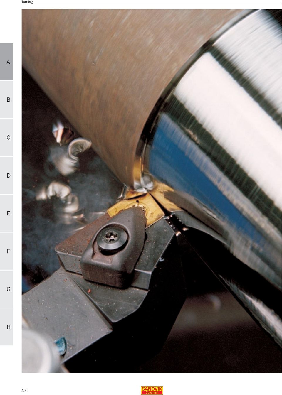
5 Turning eneral turning Single-point machining Turning, basically, generates cylindrical forms with a single point tool and in most cases the tool is stationary with the workpiece rotating. In many respects it is the most straight-forward metal cutting method with relatively uncomplicated definitions. On the other hand, being the most widely used process and easily lending itself to development, turning today is a highly optimized process, requiring thorough apprasial of the various factors in applications. In spite of generally being a single cutting-edge operation, the turning process is varied in that the workpiece shape and material, type of operation, conditions, requirements, costs, etc. determine a number of cutting tool factors. Today s turning tool is carefully designed, based on decades of experience, research and development. rom the micro geometry and tool material at its point of engagement, to the basic shape and clamping of the indexable insert through to the toolholder - shank type or modular - the tool handles the dynamics of metal cutting today in a way which would have been unthinkable a couple of decades ago. Many of the principles that apply to single-point machining apply also to other metal cutting methods, such as boring and even multi-point, rotating tool machining such as milling. There are several basic types of turning operations, requiring specific types of tools for the operation to be performed in the most efficient way. Turning is the combination of two movements: rotation of the workpiece and feed movement of the tool. In some applications, the workpiece can be stationary with the tool revolving around it to make the cut, but Turning and facing as axial and radial tool movements. Shank-type and oromant apto type tools for turning. 5

6 basically the principle is the same. The feed movement of the tool can be along the axis of the workpiece, which means the diameter of the part will be turned down to a smaller size. lternatively, the tool can be fed towards the centre (facing off), at the end of the part. Often feeds are combinations of these two directions, resulting in tapered or curved surfaces which today s N-lathe control-units, with their many program possibilities, are able to more than cope with. This part will deal mainly with external turning, leaving other, more specialized operations, such as threading, grooving, cutting off and boring to be discussed in separate application chapters. Turning can be broken down into a number of basic cuts for selecting tool types, cutting data and also programming for a certain operation. hip formation Turning has been developed to a stage where not only is metal removed at very high speeds but the parameters that make up the process are closely controlled as are the end-results in the form of component quality and reliability. hips are sheared off a workpiece according to carefully defined data that ensures correct shape and size. lthough the machining process is intended for cutting a workpiece into a specific shape, size and finish, the chips produced most comply with the those acceptable for the application as well as being necessary because of the high cutting data involved in today`s N machines. Masses of long, stringy chips would otherwise accumulate in a very short time in the machining area in uncontrollable nests of tangled swarf. This is a threat to the process and one that can endanger not only operators but also the finished component. The chip form is to a large extent influenced by the materials being cut, varying between continuous forms of ductile material to crumbling, brittle material. n orthogonal view of the chip formation is where the cutting speed direction or axis of rotation of the workpiece material being cut is at right angles to the main cutting edge. This is a simplified view of the cutting process, employed only in a few operations such as some facing and plunging. Most metal cutting is oblique, where the cutting direction is at a certain angle relative to the main edge. This changes the geometrical conditions considerably and the chip flow direction is altered. asically, instead of a watchspring type chip, as in a typical parting operation, the chip will take various forms of comma or helical shapes. The entering angle and nose radius of the tool affects the chip formation in that the chip cross-section changes. The hip control is essential in modern turning operations. Typical acceptable chips in finishing and roughing. a p a p κr hip formation varies with depth of cut, entering angle, feed, material and tool geometry. 6

7 hips are broken on their own accord (), against the tool () or against the workpiece (). a p is small in relation to the nose radius, the radius part is the main part of the cutting edge and spiral chips will be generated. larger depth leads to less influence from the radius and more from the actual entering angle of the edge with an outward directed spiral chip as the result. The feed rate, however, also affects the width of the chip cross-section and the chip flow. a p The working area of an insert geometry defined by acceptable chipbreaking for feed and depth of cut. f n f n chip thickness is reduced and the width increased with a smaller angle. The direction of chip flow is also changed, usually advantageously, with the spiral pitch being increased. epending upon the depth of cut ( O = a p ), the shape and direction of chips also vary with the nose radius on the cutting edge. When the O square chip cross-section usually means excessively hard chip compression while a wide, thin band-like chip is formed in unsuitably long strands. When the chip curve becomes smaller for a thicker chip, the chip/tool contact-length becomes longer with more deformation and pressure. xcessive thickness has a negative influence on the machining process. urthermore, if the feed rate is increased to above what the insert geometry has been designed for, the chip will pass over the chip forming geometry, with the effect that machining is performed with a negative instead of positive geometry without balanced chipbreaking. finishing insert, working mostly with its nose radius will have the geometry concentrated to the corner of the insert while a heavy roughing insert will have geometry over the rake face. 7

8 hipbreakers, as part of the insert geometry, are designed to work at different feed/depth of cut areas. Some inserts are capable of providing satisfactory chip formation across a broad intermediate range, having incorporated combinations of chipbreakers, ranging from the corner radius and across the insert. hipbreaking s shown on the previous page, there are different ways for a chip to break, mainly :. Self-breaking as with turning cast-iron. reaking against the tool. reaking against the workpiece The type of chipbreaking encountered partly depends upon the insert and tool geometry and cutting data. ny of the chipbreaking ways may cause a disadvantage but this can usually be overcome by choice of geometry or cutting data. When self-breaking, if the tool-life is unacceptable, employ a more open chipbreaker as part of the insert geometry. When breaking against the clearance face of the tool, chip-hammering may be a disadvantage and a different (tighter or open chipbreaker) geometry may be better. lternatively, adjust cutting data. When breaking a against the workpiece shoulder when large O are employed, unsatisfactory chip spraying may be encountered and a smaller entering angle should be considered. Short chipping materials need little or no chipbreaking while some long chipping materials need chipbreakers designed into the insert geometry to deform and break the chip. The initial curving of the chip is in most cases not sufficient to break the chip into required lengths. chipbreaker in its simplest form is a built-in obstruction to the chip flow. This crude form has many disadvantages and has had, in many cases, a negative effect on machining performance. Various forms of ground and later pressed indexable insert chipbreakers were developed before today s modern inserts. The modern indexable insert is a complex combination of angles, flats and radii to optimize chip formation through cutting action, contact length, chip breaking, etc. Most inserts have positive rake angles, combined with being inclined negatively in the toolholder, to promote good chip formation and positive cutting action. Negative primary lands of varying lengths depending upon the working area of the geometry, are applied to strengthen the cutting edge. hip control is, thus, one of the key factors especially in turning and drilling. Milling creates a natural chip length thanks to the limited length of cutting edge engagement. In drilling and boring, chip control is vital because of the limited space inside holes being machined. lso in modern high-performance drilling, chips have to be of exact form so as to be evacuated efficiently from the cutting zone - any congestion, quickly leads to tool breakdown. The chipbreaking diagram for an insert geometry (based on the recommended ranges of feed and depth of cut), in combination with the tool material, is the key to insert application. The modern latest programme of inserts will include cutting geometries to cover most workpiece materials. These geomtries will cover applications including finishing, semi-finishing to roughing as well as heavy duty rough machining. hip control is thus mainly exercised through the geometry of the indexable insert in combination with cutting data. a p WR a p P f n f n Typical working areas of a roughing insert and a finishing insert. 8

9 utting data The workpiece rotates in the lathe, with a certain spindle speed (n), at a certain number of revolutions per minute. In relation to the diameter of the workpiece, at the point it is being machined, this will give rise to a cutting speed, or surface speed (Vc) in m/min. This is the speed at which the cutting edge machines the surface of the workpiece and it is the speed at which the periphery of the cut diameter passes the cutting edge. The cutting speed is only constant for as long as the spindle speed and/or part diameter remains the same. In a facing operation, where the tool is fed in towards the centre, the cutting speed will change progressively if the workpiece rotates at a fixed spindle speed. On most modern N-lathes, the spindle speed is increased as the tool moves in towards the centre. or some of the cut, this makes up for the decreasing diameter but for very small diameters, and very close to the centre, this compensation will be impractical as the speed range on machines is limited. lso if a workpiece, as is often the case, has different diameters or is tapered or curved, the cutting speed should be taken into account along the variations. The feed (ƒn) in mm/rev is the movement of the tool in relation to the revolving workpiece. This is a key value in determining the quality of the surface being Longitudinal turning and facing paths with a -style insert. machined and for ensuring that the chip formation is within the scope of the tool geometry. This value influences, not only how thick the chip is, but also how the chip forms against the insert geometry. The cutting depth (ap) in mm is the difference between un-cut and cut surface. It is half of the difference between the un-cut and cut diameter of the workpiece. The cutting depth is always measured at right angles to the feed direction of the tool. The cutting edge approach to the workpiece is expressed through the entering angle (κr). This is the angle between the cutting edge and the direction of feed and is an important angle in the basic selection of a turning tool for an operation. In addition to influencing the chip formation, it affects factors such as the direction of forces involved, the length of cutting edge engaged in cut, the way in which the cutting edge makes contact with the workpiece and the variation of cuts that can be taken with the tool in question. The entering angle usually varies between 45 to 95 degrees but for profiling operations, even larger entering angles are useful. The entering angle can be selected for accessibility and to enable the tool to machine in several feed directions, giving versatility and reducing the number of tools needed. lternatively it can be made to provide the cutting edge with a larger corner and can add cutting edge strength by distributing machining pressure along a greater length of the cutting edge. It can also give strength to the tool at entry and exit of cut and it can direct forces to provide stability during the cut. v c n ap fn κ r The main cutting data/tool elements for turning tool applications. 9

10 Turning Tool geometry The cutting action is to a great extent determined by the tool geometry. The tool geometry is designed to cut various workpiece metals by forming chips in a smooth way, while also providing a strong cutting edge, and to break chips into maneageable swarf. Many indexable inserts have combinations of chipbreaking functions to cope with light cuts at the corner and larger depths of cut along the cutting edge. ach insert geometry is developed to cover an application area made up of the recommended feed and cutting depth ranges. t one end, an insert geometry for finishing will have an area comprising smaller feeds and depths while at the other end, a rough-turning geometry will have a range of large feed and depth values. n all-round insert geometry covers a large intermediate area for a large variation of operations.the finishing insert uses the geometry at the corner of the insert while the roughing one uses a relatively long part of the main cutting edge. The various chipbreakers are made up of different sizes and combinations of angles, flats and radii. Straight turning and facing operation will remain around one set of values in the application diagram, while profiling operations, with varying cutting depths and feed rates will give rise to movement or several points throughout the insert application area, providing aceptable chipbreaking. Other factors that determine the choice of insert geometry are the occurrence of intermittent machining, vibration tendencies. The amount of machine power can also determine the choice of insert geometry. Rake (γ) and inclination (λ) angles of a turning tool. λ γ - + Negative and positive basic shapes of inserts. There is a distinction in cutting edge geometry between negative and positive insert geometry. negative insert has a wedge angle of 90 degrees seen in a cross-section of the basic shape of the cutting edge. positive insert has an angle of less than 90 degrees. The negative insert has to be inclined negatively in the toolholder so as to provide a clearance angle tangential to the workpiece while the positive insert has this clearance built-in. The inclination angle (λ) is a measure of at what angle the insert is mounted in the toolholder. When the insert is mounted in the toolholder, the insert geometry and inclination in the toolholder will determine the resulting cutting angle with which the cutting edge cuts. The rake angle (γ) is a measure of the edge in relation to the cut although it is often expressed through a flat insert. The rake angle of the insert itself is usually positive and varies along the cutting edge, from the nose radius along the straight cutting edge. flat insert has a rake angle of zero degrees. The actual cutting function of the rake angle also varies along the face of the insert, back from the cutting edge, until the chipbreaking function takes over the chip formation. lso the actual cutting edge of the insert is subject to various develoment. The micro-geometry of the cutting edge is critical as regards strength and tool wear development. dge preperation along the transition between the edge face and - + the clearance face is in the form of a radius, chamfer or land and affects tool strength, power consumpion, finishing ability of the tool, vibration tendency and chip formation. The edge preparation are applied to inserts depending upon application and may vary from a ground sharp edge for finishing in light metal to a wide negative land for heavier operations in demanding materials. dge rounding (R) is the most frequently used preparation and may also be used in combination with the application of a land. The radii are measured in microns and applied with precision through a special process. The extent of edge rounding is also combined with the tool material and the coating process of indexable inserts. 10

11 Insert shape and nose radius Looking at the tool from above, the insert has a basic shape and a radius on the corners. The insert shape varies considerably and the point angle can be as little as 35 degrees extending to 100 degrees with the addition of a round insert. In between these extremes are square, triangular and rhombic shapes with point angles of 55, 60 and 80 degrees. The range gives properties ranging from the largest for highest roughing strength to the most pointed giving best profiling accessibility. With high edge strength through long cutting edge engagement of the larger point angles comes the tendency for vibrations in the machining process and high power requirement. With high edge accessibility during machining comes a weaker cutting edge. balanced choice for the operation in question is needed. The nose radius (rε) is a key factor in many turning operations and one that needs consideration as the right choice affects cutting edge strength to surface finish of the component. n insert is available in several nose radii where the smallest nose radius is theoretically zero but where 0.2 mm is more commonly the smallest. The largest is normally 2.4 mm, although the full range is not available for one and the same insert shape or size. In rough turning, the nose radius can be as large as possible for strength, without giving rise to vibration tendencies. The feed rate of the tool is also affected by the nose radius or vice versa. large nose radius provides a strong edge, capable and dependent upon high feeds for proper cutting edge engagement. The small nose radius means a weaker point but one capable of fine cuts. S κ r 90º 35º ε l l a a p l a dge strength and accesibility of a 90 degree corner insert and a 35 degree insert. orner angle (ε) comparison, cutting edge length (l), effective cutting edge length (la) and suitable entering angle (κ r ) and depth of cut (a p ). l V ε l a p l a l a Turning l r ε The nose radius of an insert is an important performance factor. 11

12 f n R max f n 2 R max = 8 x r ε x 1000 r ε f n Surface finish is largely determined by the relationship between feed and nose radius. large nose radius is stronger than a small nose radius but more prone to vibrations. Wiper insert technology In turning operations, the surface finish generated will be directly influenced by the combination of nose radius and feed rate. The surface generated by a single point tool is made up of how the nose radius moves along the workpiece surface. The theoretical maximum profile height is calculated through a simple formula, giving an indication of the values to be expected and which can be compared to the limits set out for the component to be made. lternatively, starting out with a certain nose radius and a required profile height, a starting value for the feed rate can be calculated. Wiper technology - a new perspective on feed and surface finish in turning enerating a good surface finish on turned components and becoming a demand for semi-finishing and even roughing operations. The Wiper indexable insert technology has provided turning with a new means to achieve improved production performance where the key is to being able to raise the feed rate. The generated surface finish and tolerance are affected by a combination of nose radius size, feed rate, machining stability, workpiece, tool clamping and machine condition. The conventional relationship in turning is for the surface finish to be directly related to the tool feed and the size of the nose radius. large feed will give shorter cutting times but poorer surface finish. large nose radius will generate a better surface finish and provide more strength. ut an excessively large nose radius can lead to vibration tendencies, 12

13 uidelines Two times the feed rate = Same surface finish Same feed rate = Twice as good a surface finish The Wiper technology has provided finish turning with new possibilities. unsatisfactory chipbreaking and shorter tool-life because of insufficient cutting edge engagement. In practice, therefore, the size of the insert nose radius and the feed may be limited in an operation. To upset this relationship to achieve a better surface finish at a higher feed, the Wiper technology for the indexable insert nose-radius has been developed. Principally, this has been in the form of a carefinish through the wiper effect. Similarly, the Wiper insert for turning has ben developed to provide a high capability of generating a better surface finsih. Or, put another way, is capable of generating the same finish at a much higher feed. onventionally, a turning operation can often be characterized as having a certain feed rate established for an operation. or instance, using the largest perwear too rapid. Yet feed rate remains the most direct way to lower actual machining times but does not have the marked effect on tool-life that cutting speed does. The Wiper technology is a direct means with which to improve productivity. r ISO R max r Wiper R max The Wiper insert has a completely new nose configuration. fully composed combination of radii with some insert geometry modification. The Wiper nose radius provides a smaller profile height on the generated surface cutting edge which has a smoothing out effect on the turned surface. The Wiper insert has a completely new type of nose configuration. In milling, there are specific wiper inserts which are mounted somewhat below the others in a facemill which, due to having a wider parallel land, smooths the surface to a better missable 1.2 mm nose radius at a feed rate of 0.15 mm/min might generate a surface finish of Ra 1 micron on a low-alloy steel component. If the feed rate is doubled, the surface finish obtained will be in the region of Ra 2.5. When the feed is raised within the application area of the insert geometry, the surface finish often becomes unsatisfactory. hanging the feed rate can also lead to chip control being unsatisfactory, the cutting edge load excessive and tool The Wiper insert has an adapted chipbreaker while conventional nose-radius insert has a geometry that limits feed rates before that of a Wiper insert. The Wiper chipbreaking ability has been adapted to be in line with the modified nose radius and higher feed-capability. hip control therefore extends over new areas beyond conventional cutting data limitations. This is one of the reasons why Wiper inserts are now also often seen as problem solvers in turning operations where unacceptable chip forms create problems. 13

14 This catalogue has been split into smaller parts to enhance downloading speeds. If you want to view the next page please click R! (To go back to the last viewed page, use the integrated green arrows at the bottom of the crobat user interface)

is decisive if contour turning is involved.
 Toolholder selection The clamping system of the insert in the toolholder should be selected first. Toolholders have been ed to provide optimum performance in different applications and usually over a broad
Boring. Contents. Boring
 ontents oring oring ackground... 3 oring operation types... 4 oring tools... 5 hoice of boring tool type... 6 Roughing... 6 inishing... 7 Inserts for boring... 8 uilding and setting boring tools... 9 Ways
Parting and Grooving. External operations : 1. Parting off, 2. Grooving, 3. Turning, 4. Profiling, 5. Undercutting, 6. Face-grooving, 7.
 PRTIN N ROOVIN Parting and rooving utting off and making grooves In parting operations, the objective is to seperate, as efficiently and reliably as possible. one part of the workpiece from the other.
GEOMETRY OF SINGLE POINT TURNING TOOLS
 GEOMETRY OF SINGLE POINT TURNING TOOLS LEARNING OBJECTIVES Introduction to Features of single point cutting tool. Concept of rake and clearance angle and its importance System of description of Tool geometry
Milling. Contents. Milling
 ontents Milling The Milling process... 5 asic milling definitions... 6 pplication of milling cutters... 9 Milling direction... 9 utter diameter position... 10 ntry and exit considerations... 11 ntering
Milling. COPYRIGHT 2008, Seco Tools AB 1/111
 Milling 1/111 2/111 Milling A simple choice! Experts required? No Just follow some basic rules. 3/111 Face milling 4/111 Square shoulder milling 5/111 Disc milling 6/111 Copy milling 7/111 Plunge milling
Product Guide SaraDrill
 Product Guide SaraDrill SARADRILL / A QUICK GUIDE Drilling from solid - a proven technology to drill large diameter holes on low horse power machines. Drilling from 49mm to 270mm diameter holes from solid
Chapter 6 Machining Center Carbide Insert Fundamentals
 This sample chapter is for review purposes only. Copyright The Goodheart-Willcox Co., Inc. All rights reserved. N10G20G99G40 N20G96S800M3 N30G50S4000 N40T0100M8 N50G00X3.35Z1.25T0101 N60G01X3.25F.002 N70G04X0.5
Advantages and application of PCD and CBn tools
 PCD and CBN tools Advantages and application of PCD and CBn tools Powerful and economical Tools with PCD and CBN cutting edges are the ideal solution for difficult-to machine, highly abrasive materials.
Table of contents BRAZED TURNING TOOLS. Toolholders H 2. Tips H 6. Rods H 8. Technical information H 9 H 1
 Table of contents BRAZED TURNING TOOLS Toolholders 2 Tips 6 Rods 8 9 1 ISO External holders General turning External Ordering Tip According to ISO243-1975 (DIN 4982-198) h b l 1 f 1 f 2 a p r ε γ 1) λ
Milling & Machining Centers
 Training Objective After watching the program and reviewing this printed material, the viewer will gain knowledge and understanding of basic milling theories and procedures. In addition, the viewer will
New cutting tools from Sandvik Coromant
 Supplement to Main Catalogue 2006 New cutting tools from Sandvik Coromant TURNING - MILLING - DRILLING - ORING - TOOLHOLDING CoroPak 2006.1 790 new products introduced! No compromise! With the new generation
High speed machining and conventional die and mould machining
 High speed machining and conventional die and mould machining Reprint from HSM - High Speed Machining There are a lot of questions about HSM today and many different, more or less complicated, definitions
Think precision, Think HSS REAMING
 Think precision, Think HSS REAMING SUMMARY REAMING TOOLS 2 Zoom on a reamer 3 Which HSS for maximum efficiency? 4 Coatings for the best performance 5 Vocabulary 6 Choose the right design 7 Types of bevel
FRAUNHOFER INSTITUTE FOR MACHINE TOOLS AND FORMING TECHNOLOGY IWU HYBRID MACHINING PROCESSES IN CUTTING TECHNOLOGY
 FRAUNHOFER INSTITUTE FOR MACHINE TOOLS AND FORMING TECHNOLOGY IWU HYBRID MACHINING PROCESSES IN CUTTING TECHNOLOGY VIBRATION-SUPERIMPOSED MACHINING Hybrid Machining Processes Principle Process Variants
HOBBING MACHINE TYPE ZFWZ 8000x40
 Inventory number 416/635 Year of production 1973 Serial number 7160 HOBBING MACHINE TYPE ZFWZ 8000x40 Application The machine is provided for milling cylindrical, helical and helix cogwheels. The tooth
UNITED STATES CUTTING TOOL INSTITUTE Product Groupings for Standards Activities CUTTING TOOL PRODUCTS
 CUTTING TOOL PRODUCTS 1. BORING ISO 5609 Boring bars for indexable inserts Dimensions ISO 6261 Boring bars (tool holders with cylindrical shank) for indexable inserts Designation JIS B 4128 Boring bars
Contents. Drilling. The drilling process... E3. Drill selection procedure... E7. Application of drills... E14
 ontents rilling rilling The drilling process... 3 rilling... 3 utting data... 4 achining holes... 4 utting forces and power... 5 hip control and cutting fluid... 6 rill selection procedure... 7 electing
DEUTSCHE NORM June 1998. Forms and dimensions of undercuts
 DEUTSCHE NORM June 1998 Forms dimensions of s { 509 ICS 01.100.20; 25.020 Descriptors: Undercuts, types, dimensions, technical drawings. Supersedes August 1966 edition. Freistiche Formen, Maße In keeping
Screw Thread Design. Rev. 3-4-09
 Screw Thread Design Screw Thread Fundamentals A screw thread is defined as a ridge of uniform section in the form of a helix on either the external or internal surface of a cylinder. Internal threads refer
CNC Applications Speed and Feed Calculations
 CNC Applications Speed and Feed Calculations Photo courtesy ISCAR Metals. Turning Center Cutters What types of cutters are used on CNC turning Centers? Carbide (and other hard materials) insert turning
Removing chips is a method for producing plastic threads of small diameters and high batches, which cause frequent failures of thread punches.
 Plastic Threads Technical University of Gabrovo Yordanka Atanasova Threads in plastic products can be produced in three ways: a) by direct moulding with thread punch or die; b) by placing a threaded metal
8.1 HPC for improved efficiency on standard machine tools by using new fluid-driven spindles
 8.1 HPC for improved efficiency on standard machine tools by using new fluid-driven spindles A. Schubert 1, O. Harpaz 2, B. Books 2, U. Eckert 1, R. Wertheim 1 1 Fraunhofer IWU, Reichenhainer Str. 88,
METALWORKING PRODUCTS. Deep hole drilling Product catalogue and application guide
 METALWORKING PRODUCTS Deep hole drilling Product catalogue and application guide AB Sandvik Coromant Not only a tool supplier Sandvik Coromant is the No.1 supplier of cutting tools for the metalworking
Force measurement. Forces VECTORIAL ISSUES ACTION ET RÉACTION ISOSTATISM
 Force measurement Forces VECTORIAL ISSUES In classical mechanics, a force is defined as "an action capable of modifying the quantity of movement of a material point". Therefore, a force has the attributes
Radius Compensation G40, G41, & G42 (cutter radius compensation for machining centers, tool nose radius compensation for turning centers)
") Radius Compensation G40, G41, & G42 (cutter radius compensation for machining centers, tool nose radius compensation for turning centers) These features are commonly well covered in most basic CNC courses.
Radius Compensation G40, G41, & G42 (cutter radius compensation for machining centers, tool nose radius compensation for turning centers) These features are commonly well covered in most basic CNC courses.
Milling and Machining Center Basics
 Training Objectives After watching the video and reviewing this printed material, the viewer will gain knowledge and understanding of basic milling theories and procedures. In addition, the viewer will
MACHINING OPERATIONS AND MACHINE TOOLS
 MACHINING OPERATIONS AND MACHINE TOOLS 1. Turning and Related Operations 2. Drilling and Related Operations 3. Milling 4. Machining & Turning Centers 5. Other Machining Operations 6. Shape, Tolerance and
Manufacturing Tooling Cutting Tool Design. Elements of Machining. Chip Formation. Nageswara Rao Posinasetti
 Manufacturing Tooling Cutting Tool Design Nageswara Rao Posinasetti Elements of Machining Cutting tool Tool holding Guiding device Work piece Machine tool January 29, 2008 Nageswara Rao Posinasetti 2 Chip
Milling Milling milling cutter milling machines 1
 Milling Milling is a basic machining process by which a surface is generated progressively by the removal of chips from a workpiece as it is fed to a rotating cutter in a direction perpendicular to the
ME 1355 CAD/CAM LABORATORY CNC MILLING PROGRAM. Study of G Codes and M Codes to Write Manual Part Programming for Fanuc Control Systems
 ME 1355 CAD/CAM LABORATORY CNC MILLING PROGRAM Ex.No.1 Study of G Codes and M Codes to Write Manual Part Programming for Fanuc Control Systems PREPARATORY FUNCTION ( G CODES ) The preparatory functions
6.6 GEAR MANUFACTURING. Introduction. Gear forming
 Valery Marinov, Manufacturing Technology Gear Manufacturing 123 6.6 GEAR MANUFACTURING Introduction Because of their capability for transmitting motion and power, gears are among the most important of
Cutting and Shearing die design Cutting die design
 Manufacturing Processes 2 Dr. Alaa Hasan Ali Cutting and Shearing die design Cutting die design A stamping die is a special, one-of-a-kind precision tool that cuts and forms sheet metal into a desired
Technical Data. 7. Bearing Fits. 7.1 Interference. 7.2 Calculation of interference F B LLLLLLLLL( A-54
 Technical Data 7. Bearing Fits 7.1 Interference For rolling s the rings are fixed on the or in the housing so that slip or movement does not occur between the mated surface during operation or under. This
Milling Chuck Features
 Milling Chuck Features Since its first introduction into the industry in 1963, Nikken has sold over 2,000,000 worldwide and never stopped improving its original design. Featuring multi-roller bearings
zeus Marking Technology
 zeus Marking Technology Marking Tools Marking Rolls Engraving Technology Die Premium-Marke von Hommel+Keller zeus MARKING TECHNOLOGY zeus is a premium brand that stands for highest quality, precision,
indexable Center Drill
 Our innovative tooling design upgrades productivity and competitive capability while reducing production requirements in a range of industries. The tooling system is designed to benefit users of machining
CNC 8055 / CNC 8055i SELF-TEACHING MANUAL ( TC OPTION) (REF 0607) (Ref 0607)
 (REF 0607) (Ref 0607)") CNC 8055 / CNC 8055i (REF 0607) SELF-TEACHING MANUAL ( TC OPTION) (Ref 0607) All rights reserved. No part of this documentation may be copied, transcribed, stored in a data backup system or translated
CNC 8055 / CNC 8055i (REF 0607) SELF-TEACHING MANUAL ( TC OPTION) (Ref 0607) All rights reserved. No part of this documentation may be copied, transcribed, stored in a data backup system or translated
PROVEN SOLUTIONS FLIUD END MACHINING FLUID END MACHINING PROVEN SOLUTIONS & TOOLING
 PROVEN SOLUTIONS FLIUD END MACHINING FLUID END MACHINING PROVEN SOLUTIONS & TOOLING SECO PROVEN SOLUTIONS WILL IMPROVE YOUR PROCESS When you partner with Seco, our team of metalworking experts evaluate
Heavy Roughning Milling Cutter. MSR Series. Improving machine efficinecy. Double the productivity. Square Insert MSR Facemill. Insert lineup expanded
 Heavy Roughning Milling Cutter MSR Series Improving machine efficinecy Square Insert MSR Facemill MonSteR M S R Square S Mill Double the productivity MonSteR M S R Mill Insert lineup expanded Heavy Milling
How To Improve Your Turning
 Best practice machining of wind power components Tool and method advances for efficient manufacturing WIND POWER EDITORIAL Introduction Manufacturing parts for the wind-power industry is an opportunity
Sheet Metal Shearing & Bending
 Training Objective After watching the program and reviewing this printed material, the viewer will gain a knowledge and understanding of the principles and machine methods of shearing and bending sheetmetal
SprutCAM is a CAM system for NC program generation for machining using multi-axis milling, turning, turn/mill, Wire EDM numerically controlled
 SprutCAM is a CAM system for NC program generation for machining using multi-axis milling, turning, turn/mill, Wire EDM numerically controlled machines and machining centers. The system enables the creation
Lapping and Polishing Basics
 Lapping and Polishing Basics Applications Laboratory Report 54 Lapping and Polishing 1.0: Introduction Lapping and polishing is a process by which material is precisely removed from a workpiece (or specimen)
Easy Machining Center Setup
 White Paper Document No. MWA-072-EN_01_1404 April 2014 Easy Machining Center Setup Using FANUC s Direct Input of Workpiece Origin Setting Measured and Tool Length Measurement features to easily establish
Making 3D Threads in Feature Based Solid Modelers
 Making 3D Threads in Feature Based Solid Modelers THREAD BASICS Making true geometric threads in feature-based solid modelers is a fairly straightforward process and can be handled using several different
Overview. Milling Machine Fundamentals. Safety. Shop Etiquette. Vehicle Projects Machine Shop
 Overview Milling Machine Fundamentals Wayne Staats, UW-Madison FSAE Safety Shop Etiquette Before Machining Indicating Calculating Feeds and Speeds Machining Maintenance Safety Respect the machines Common
DUGARD. Machine Tools Since 1939. Dugard 700L Series Heavy Duty CNC Lathes. www.dugard.com
 DUGARD Machine Tools Since 1939 Dugard 700L Series Heavy Duty CNC Lathes www.dugard.com Dugard 700L Heavy Duty CNC Lathe 2000, 3000 or 4000mm bed length Designed for easy and convenient operation The concave
MaraMeter. Indicating Snap Gages
 - 9-2 MaraMeter. Indicating Snap Gages Overview MaraMeter. The Indicating Snap Gage is ideal for highly accurate and reliable results on cylindrical work pieces with a narrow tolerance. MaraMeter 840 F
THE INFLUENCE OF STEEL GRADE AND STEEL HARDNESS ON TOOL LIFE WHEN MILLING IN HARDENED TOOL STEEL
 THE INFLUENCE OF STEEL GRADE AND STEEL HARDNESS ON TOOL LIFE WHEN MILLING IN HARDENED TOOL STEEL S. Gunnarsson, B. Högman and L. G. Nordh Uddeholm Tooling AB Research and Development 683 85 Hagfors Sweden
CUTTING TOOL TECHNOLOGY. 1. Tool life 2. Tool Materials 3. Tool Geometry 4. Cutting fluids
 CUTTING TOOL TECHNOLOGY 1. Tool life 2. Tool Materials 3. Tool Geometry 4. Cutting fluids 1 Introduction Machining is accomplished by cutting tools. Cutting tools undergo high force and temperature and
F 02 2-04-17 18.10 Sida F 2 HEAVY MACHINING F 2
 HEAVY MACHINING 2 Table of contents HEAVY MACHINING Heavy turning Introduction Inserts Cutting data recommendations 4 5 9 Spare parts for HD cassettes 10 Technical information 11 Bar peeling Introduction
Power generation. Tool and method advances for efficient manufacturing
 Power generation Tool and method advances for efficient manufacturing POWER GENERATION - EDITORIAL Introduction World power consumption is predicted to rise by some 20% in the period up to the middle of
SCREW THREADS C H A P T E R 17
 C H A P T E R 17 SCREW THREADS Screw threads are of prime importance in machine drawing. It is a functional element used as temporary fasteners such as bolt, stud, nut and screw etc. These are constructed
Computer-Aided Numerical Control (CNC) Programming and Operation; Lathe Introduction, Advanced Mills
 Programming and Operation; Lathe Introduction, Advanced Mills") 1 of 6 9/9/2014 3:59 PM I. Catalog Information Credit- Degree applicable Effective Quarter: Fall 2014 MCNC 75B Computer-Aided Numerical Control (CNC) Programming and Operation; Lathe Introduction, Advanced
1 of 6 9/9/2014 3:59 PM I. Catalog Information Credit- Degree applicable Effective Quarter: Fall 2014 MCNC 75B Computer-Aided Numerical Control (CNC) Programming and Operation; Lathe Introduction, Advanced
3-Component Measuring System
 Force 3-omponent Measuring System for utting Force Measurement During Turning Modular system for measurement of cutting forces when turning outside and inside diameters on turret lathes. Machine adapters
Lecture slides on rolling By: Dr H N Dhakal Lecturer in Mechanical and Marine Engineering, School of Engineering, University of Plymouth
 Lecture slides on rolling By: Dr H N Dhakal Lecturer in Mechanical and Marine Engineering, School of Engineering, University of Plymouth Bulk deformation forming (rolling) Rolling is the process of reducing
Teachware CNC Technology
 Teachware CNC Technology Contents CNC Basics CNC Turning CNC Milling CAD/CAM Turning & Milling CNC Basics - Excerpt MTS TeachWare Student s Book - MTS GmbH 1999 MTS Mathematisch Technische Software-Entwicklung
Course outline. Know Your Machine From A Programmer s Viewpoint 11 If you ve had experience with conventional (non-cnc) machine tools 11
 machine tools 11") Course outline Know Your Machine From A Programmer s Viewpoint 11 If you ve had experience with conventional (non-cnc) machine tools 11 Machine Configurations 13 Vertical machining centers 13 C-frame style
Course outline Know Your Machine From A Programmer s Viewpoint 11 If you ve had experience with conventional (non-cnc) machine tools 11 Machine Configurations 13 Vertical machining centers 13 C-frame style
Index. Illustrations CERAMIC PRODUCTIVITY MANUAL. Page. Page
 CERAMIC PRODUCTIVITY MANUAL Index Page What is a Whisker-Reinforced Ceramic...4 WG-300 Fracture Surface...4 Physical Properties...5 How to Use the Properties of Greenleaf Advanced Ceramics...6 Relative
Cutting Tool Materials
 Training Objectives After watching the video and reviewing this printed material, the viewer will gain knowledge and understanding of cutting tool metallurgy and specific tool applications for various
U-Max Chamfering endmill SPMT-WL 0.17 (0.08-0.21) -WH 0.35 (0.10-0.42) R215.64. Long edge cutter 215.3 0.17 (0.10-0.20) R215.3 -AAH 0.12 (0.08-0.
 -WH 0.35 (0.10-0.42) R215.64. Long edge cutter 215.3 0.17 (0.10-0.20) R215.3 -AAH 0.12 (0.08-0.") General Turning PROFILING Feed recommendations Feed per tooth, fz (mm/tooth) Insert geometry Insert size Starting value (min.- max.) U-Max Chamfering endmill SPMT-WL 0.17 (0.08-0.21) -WH 0.35 (0.10-0.42)
General Turning PROFILING Feed recommendations Feed per tooth, fz (mm/tooth) Insert geometry Insert size Starting value (min.- max.) U-Max Chamfering endmill SPMT-WL 0.17 (0.08-0.21) -WH 0.35 (0.10-0.42)
Introduction to JIGS AND FIXTURES
 Introduction to JIGS AND FIXTURES Introduction The successful running of any mass production depends upon the interchangeability to facilitate easy assembly and reduction of unit cost. Mass production
GEAROLOGY 4-1 WORMS AND WORM GEARS WORMS AND WORM GEARS
 GEAROLOGY 4-1 4 4-2 GEAROLOGY COMMON APPLICATIONS: Worm and worm gear sets are used in many, everyday products including: electrical mixers, hubometers, right Now that you have an understanding of two
7.3 Fit selection. Inner ring: Rotating. Outer ring: Stationary. Inner ring: Stationary. Outer ring: Rotating. Inner ring: Stationary
 7. Bearing Fits 7. Fitting For rolling s, inner and outer rings are fixed on the or in the housing so that relative movement does not occur between fitting surfaces during operation or under. This relative
Cutting Processes. Simulation Techniques in Manufacturing Technology Lecture 7
 Cutting Processes Simulation Techniques in Manufacturing Technology Lecture 7 Laboratory for Machine Tools and Production Engineering Chair of Manufacturing Technology Prof. Dr.-Ing. Dr.-Ing. E.h. Dr.
This last dimension, the thread pitch diameter, is the most important as it is a reference from which all other thread measurements originate
 Training Objectives After watching the video and reviewing this printed material, the viewer will gain knowledge and understanding of the design and use of various thread types and how they are produced.
Technical Information
 tapping Technical Information Troubleshooting Guide 115 TAP DOES NOT START Program depth: Tap drill size: Tap sharpness: Compression stroke may use up the entire program depth. Check for tap drill size.
DUGARD. Machine Tools Since 1939. Dugard 400 Slant Bed High Precision CNC Lathe. www.dugard.com
 DUGARD Machine Tools Since 1939 Dugard 400 Slant Bed High Precision CNC Lathe www.dugard.com Superb Performance, Maximum Stability, Maximum Reliability Precision, Power and Capacity Make the Dugard 400
A Fuzzy System Approach of Feed Rate Determination for CNC Milling
 A Fuzzy System Approach of Determination for CNC Milling Zhibin Miao Department of Mechanical and Electrical Engineering Heilongjiang Institute of Technology Harbin, China e-mail:[email protected]
COATED CARBIDE. TiN. Al 2 O 3
 COATED CARBIDE GENERAL INFORMATION CVD = Chemical Vapour Deposition coated grades GC2015, GC2025, GC2135, GC235, GC3005, GC3015, GC3020, GC3025, GC3115, GC4015, GC4025, GC4035, S05F, and CD1810. PVD =
Home"" """"> ar.cn.de.en.es.fr.id.it.ph.po.ru.sw
 Home"" """"> ar.cn.de.en.es.fr.id.it.ph.po.ru.sw Milling of Grooves, Elongated Slots and Break-throughs - Course: Techniques for machining of material. Trainees' handbook of lessons (Institut fr Berufliche
Pole Lathe and Shave Horse Design
 Pole Lathe and Shave Horse Design These pictures and accompanying words are Copyright Michael Hughes February 2002. They are not to be re-produced, in part or whole, without permission from the author.
Product information. QM eco select Disc erosion machine for the machining of PCD tools
 Product information QM eco select Disc erosion machine for the machining of PCD tools QM eco select The Idea. High-precision machining of PCD tools. The VOLLMER QM eco select is for the machining of tools
AISI O1 Cold work tool steel
 T OOL STEEL FACTS AISI O1 Cold work tool steel Great Tooling Starts Here! This information is based on our present state of knowledge and is intended to provide general notes on our products and their
1001 Business Center Drive Mount Prospect, IL 60056-2181 Toll Free: (800) 950-5202 Phone: (847) 635-0044 Fax: (847) 635-7866
 950-5202 Phone: (847) 635-0044 Fax: (847) 635-7866") 1001 Business Center Drive Mount Prospect, IL 60056-2181 oll Free: (800) 950-5202 Phone: (847) 635-0044 Fax: (847) 635-7866 http://www.sumicarbide.com Sumitomo offers advanced milling, drilling, and hard
1001 Business Center Drive Mount Prospect, IL 60056-2181 oll Free: (800) 950-5202 Phone: (847) 635-0044 Fax: (847) 635-7866 http://www.sumicarbide.com Sumitomo offers advanced milling, drilling, and hard
OD 1401 9 PRECISION MEASURING INSTRUMENTS
 SUBCOURSE EDITION OD 1401 9 PRECISION MEASURING INSTRUMENTS PRECISION MEASURING INSTRUMENTS SUBCOURSE OD1401 EDITION 9 Unites States Army Combined Arms Support Command Fort Lee, VA 23801-1809 5 CREDIT
NEW INTERCHANGEABLE REAMING HEAD SYSTEM FAST
 August 2007 / NEW029.1 / PAGE 1 OF 7 NEW INTERCHANGEABLE REAMING HEA YTEM FAT ACCURATE GOO FINIH Ingersoll is introducing the QwikReam, a new high speed reaming system. The QwikReam consists of an interchangeable
Belt Conveyor Tracking V-Guide vs. Crowned Roller
 Belt Conveyor Tracking V-Guide vs. Crowned Roller By: Michael A. Hosch P.E. Dorner Mfg. Corp. 1 One of the largest maintenance issues associated with belt conveyors is belt tracking. Belt tracking is the
It simply works! Safe process monitoring.
 It simply works! Safe process monitoring. A solution that simply works. It simply works: BK Mikro All safely under control: In automated manu facturing there is an enormous range of possible uses for the
Geometry and dimensional tolerances of engine bearings
 Geometry and dimensional tolerances of engine bearings Dr. Dmitri Kopeliovich (Research & Development Manager.) 1. Hydrodynamic lubrication Engine bearings operate mostly in the hydrodynamic regime of
BSME Series SEXC Series
 TOOLING NEWS E-124 P M K N S H CBN Small Hole Boring Bar Systems BSME Series SEXC Series BSME SEXC Series with brazed CBN cutting edge Minimum bore diameter = 2,5mm Series with indexable CBN insert Minimum
CH 6: Fatigue Failure Resulting from Variable Loading
 CH 6: Fatigue Failure Resulting from Variable Loading Some machine elements are subjected to static loads and for such elements static failure theories are used to predict failure (yielding or fracture).
Machine devices, jig devices
 Machine devices, jig devices 853 K0697 Rolled thread studs DIN 6379 Material: Tempered steel. KIPP Rolled thread studs DIN 6379 Order No. D L B1 B2 Approx. weight g Surface finish: Thread rolled. Class
5-Axis Test-Piece Influence of Machining Position
 5-Axis Test-Piece Influence of Machining Position Michael Gebhardt, Wolfgang Knapp, Konrad Wegener Institute of Machine Tools and Manufacturing (IWF), Swiss Federal Institute of Technology (ETH), Zurich,
Gear Cutting Tools. Hobbing Gear Milling. Leitz Metalworking Technology Group
 Gear Cutting Tools Hobbing Gear Milling Leitz Metalworking Technology Group Important information Important information 4 Services 5 An introduction to FETTE 6 Page Important information Product range
Structural Integrity Analysis
 Structural Integrity Analysis 1. STRESS CONCENTRATION Igor Kokcharov 1.1 STRESSES AND CONCENTRATORS 1.1.1 Stress An applied external force F causes inner forces in the carrying structure. Inner forces
Effect of tool geometry variation on finish turning A Review
 Journal of Engineering Science and Technology Review 4 (1) (2011) 1-13 Review Article JOURNAL OF Engineering Science and Technology Review www.jestr.org Effect of tool geometry variation on finish turning
Three Key Elements of a Cutting Tool
 End Mill Training Three Key Elements of a Cutting Tool Geometry Cutting Tool 3 Elements Needed in a Good Cutting Tool Well Balanced For Best Performance Only Good as the Weakest Link End Mill Terms A -
Driven Toolholders for SAUTER Turrets
 Driven Toolholders for SAUTER Turrets Manufacturer of Precision Tools since 1974 INNOVATION PRECISION INDIVIDUALITY QUALITY SERVICE Table of Contents Type Page Driven Toolholders DIN 5482 - Disc-type Turrets
Cerobear Spindle Bearings for Machine Tool Applications
 Cerobear Spindle Bearings for Machine Tool Applications Cerobear Spindle Bearings About CEROBEAR Committed to the abbreviation CEramic in ROlling BEARings, CEROBEAR GmbH is the renowned world leader in
Copyright 2011 Casa Software Ltd. www.casaxps.com. Centre of Mass
 Centre of Mass A central theme in mathematical modelling is that of reducing complex problems to simpler, and hopefully, equivalent problems for which mathematical analysis is possible. The concept of
Lathe Milling Attachment
 Lathe Milling Attachment By L C. MASON BY CLEVERLY stacking cold-rolled flat stock together, T-slots and slide for this lathe milling attachment are made without costly machinery. In fact, only two tools,
INSTRUCTIONS FOR CHAIN LINK INSTALLATION Chain Link fence & Posts Meshdirect.co.uk
 INSTRUCTIONS FOR CHAIN LINK INSTALLATION Chain Link fence & Posts Meshdirect.co.uk This guide explains how to correctly install our chain link fencing and post system. The guide provides details of the
Atling proudly presents the next generation self centering steady rests ATLING. Ockelbo Sweden. AX Steady Rests
 Atling proudly presents the next generation self centering steady rests ATLING Ockelbo Sweden AX Steady Rests 1 The New AX Steady Rest The Atling AX series is the result of several years of development
Surface Machining. NATIONAL INSTITUTE FOR AVIATION RESEARCH Wichita State University. Revision 5.13 Copyright 2004. All rights reserved.
 Surface Machining NATIONAL INSTITUTE FOR AVIATION RESEARCH Wichita State University Revision 5.13 Copyright 2004. All rights reserved. www.cadcamlab.org None of this material may be reproduced, used or
VCE VET ENGINEERING STUDIES
 Victorian Certificate of Education 2013 SUPERVISOR TO ATTACH PROCESSING LABEL HERE STUDENT NUMBER Letter Figures Words VCE VET ENGINEERING STUDIES Written examination Section Wednesday 20 November 2013
KIRÁLY TRADING KFT H-1151 Budapest Mogyoród útja 12-14 tel: 061307-3801 [email protected]. Clamps Clamping devices
 04000 Clamps Clamping devices 23000 22000 21000 20000 09000 08000 07000 06000 05000 04000 03000 02000 01000 297 04010 Adjustable straps Tempered steel 1.1191 Black oxide finish nlm 04010-101 Suitable thrust
Die casting Figure M2.3.1
 Die casting Die casting is a moulding process in which the molten metal is injected under high pressure and velocity into a split mould die. It is also called pressure die casting. The split mould used