Microprocessor/Microcontroller. Introduction
|
|
|
- Stewart Wilson
- 9 years ago
- Views:
Transcription
1 Microprocessor/Microcontroller Introduction

2 Microprocessor/Microcontroller microprocessor - also known as a CU or central processing unit - is a complete computation engine that is fabricated on a single chip. The first microprocessor was the Intel 4004, introduced in The 4004 was not very powerful - all it could do was add and subtract, and it could only do that 4 bits at a time. But it was amazing that everything was on one chip. rior to the 4004, engineers built computers either from collections of chips or from discrete components (Transistors and such). The 4004 powered one of the first portable electronic calculators. (excerpts from How Microprocessors Work by Marshall Brain)

3 Microprocessor/Microcontroller The first microprocessor to make it into a home computer was the Intel 8080, a complete 8-bit computer on one chip, introduced in The first microprocessor to make a real splash in the market was the Intel 8088, introduced in 1979 and incorporated into the IBM C (which first appeared around 1982). If you are familiar with the C market and its history, you know that the C market moved from the 8088 to the to the to the to the entium to the entium II to the entium III to the entium 4. ll of these microprocessors are made by Intel and all of them are improvements on the basic design of the The entium 4 can execute any piece of code that ran on the original 8088, but it does it about 5,000 times faster! (excerpts from How Microprocessors Work by Marshall Brain)

4 Microprocessor/Microcontroller :
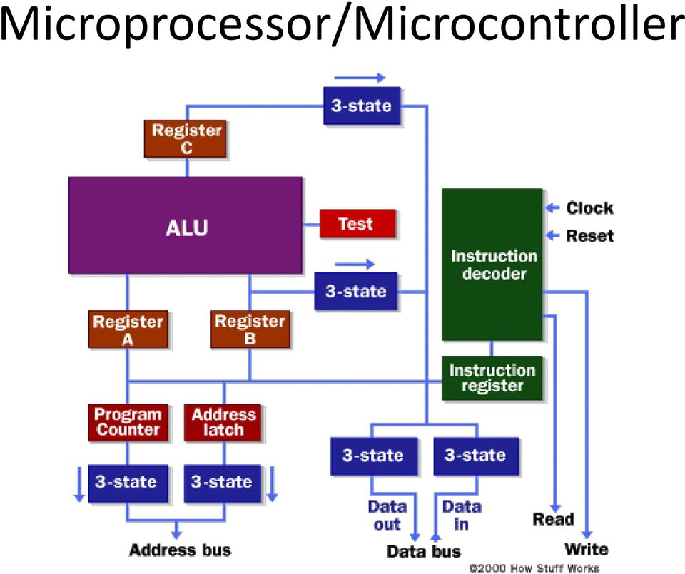
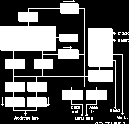
5 Microprocessor/Microcontroller This is about as simple as a microprocessor gets. This microprocessor has: n address bus (that may be 8, 16 or 32 bits wide) that sends an address to memory data bus (that may be 8, 16 or 32 bits wide) that can send data to memory or receive data from memory n RD (read) and WR (write) line to tell the memory whether it wants to set or get the addressed location clock line that lets a clock pulse sequence the processor reset line that resets the program counter to zero (or whatever) and restarts execution Let's assume that both the address and data buses are 8 bits wide in this example.
 and restarts execution")
6 Microprocessor/Microcontroller Here are the components of this simple microprocessor: Registers, B and C are simply latches made out of flip-flops. The address latch is just like registers, B and C. The program counter is a latch with the extra ability to increment by 1 when told to do so, and also to reset to zero when told to do so.

7 Microprocessor/Microcontroller Microprocessor Instructions Even the incredibly simple microprocessor shown in the previous example will have a fairly large set of instructions that it can perform. The collection of instructions is implemented as bit patterns, each one of which has a different meaning when loaded into the instruction register. Humans are not particularly good at remembering bit patterns, so a set of short words are defined to represent the different bit patterns. This collection of words is called the assembly language of the processor. n assembler can translate the words into their bit patterns very easily, and then the output of the assembler is placed in memory for the microprocessor to execute.

8 Microprocessor/Microcontroller Here's the set of assembly language instructions that the designer might create for the simple microprocessor in our example: LOD mem - Load register from memory address LODB mem - Load register B from memory address CONB con - Load a constant value into register B SVEB mem - Save register B to memory address SVEC mem - Save register C to memory address DD - dd and B and store the result in C SUB - Subtract and B and store the result in C MUL - Multiply and B and store the result in C DIV - Divide and B and store the result in C

9 Microprocessor/Microcontroller COM - Compare and B and store the result in test JUM addr - Jump to an address JEQ addr - Jump, if equal, to address JNEQ addr - Jump, if not equal, to address JG addr - Jump, if greater than, to address JGE addr - Jump, if greater than or equal, to address JL addr - Jump, if less than, to address JLE addr - Jump, if less than or equal, to address STO - Stop execution

10 Microprocessor/Microcontroller n opcode (operation code) is the portion of a machine language instruction that specifies the operation to be performed. Their specification and format are laid out in the instruction set architecture of the processor in question (which may be a general CU or a more specialized processing unit). part from the opcode itself, an instruction normally also has one or more specifiers for operands (i.e. data) on which the operation should act, although some operations may have implicit operands, or none at all.
.")
11 Microprocessor/Microcontroller ssembly language, or just assembly, is a lowlevel programming language, which uses mnemonics, instructions and operands to represent machine code. This enhances the readability while still giving precise control over the machine instructions.

12 DT DIRECTION ROM-8KB RM-256 bytes EEROM-512 bytes ULSE CCUMULT OR ERIODIC INTERRUT CO WT CHDOG O C 1 I OC2 OC3 OC4 OC5 IC1 IC2 IC3 ORT E7 E6 E5 E4 E3 E2 E1 E0 ORT E /D CONVERTER SI SCI SS SCK MOSI MISO TxD RxD ORT D D5 D4 D3 D2 D1 D0 V REFH V REFL M68HC11 CU RESET DDRESS DT BUS XIRQ INTERRUTS IRQ (V BULK ) HNDSHKE I/O XTL EXTL OSCILLTOR ORT B DT DIRECTION C ORT C RLLEL I/O E MOD LIR MODB (V STBY ) MODE SELECT B 7 B 6 B 5 B 4 B 3 B 2 B 1 B 0 C 7 C 6 C 5 C 4 C 3 C 2 C 1 C 0 S T R B S T R SINGLE CHI V DD OWER D 7 D 6 D 5 D 4 D 3 D 2 D 1 D 0 R/W S EXND V SS Figure HC118 block diagram (redrawn with permis sion of Motorola)

13 7 ccumulator 0 7 ccumulator B 0 15 Double ccumulator D 0 15 Index Register IX 0 15 Index Register IY 0 15 Stack pointer 0 15 rogram Counter 0 :B D IX IY S C S X H I N Z V C CCR Carry Overflow Zero Negative I interrupt mask Half-Carry (from bit 3) X Interrupt Mask Stop Disable Figure 1.3 MC68HC11 rogrammer's model
 X Interrupt Mask Stop Disable Figure 1.")
14 Microprocessor/Microcontroller Memory ddressing Memory consists of addressable locations memory location has 2 components: address and contents address contents Data transfer between CU and memory involves address bus and data bus address bus lines CU memory data bus lines Figure 1.5 Data transfer between CU and memory

15 DDRESSING MODES Operands needed in an instruction are specified by one of the 6 addressing modes Immediate mode Direct mode Extended mode Indexed mode Inherent mode Relative mode Microprocessor/Microcontroller

16 68HC11 addressing modes Table 1.1 refix for number representation Base binary octal decimal hexadecimal refix nothing* $ *Note: Some assemblers use & Microprocessor/Microcontroller

17 Immediate mode The actual operand is contained in the byte or bytes immediately following the instruction opcode LD #22 DD LDD #1000 Note that the (#) is a critical assembler directive! Microprocessor/Microcontroller

18 Direct mode one-byte value is used as the address of a memory operand (located in on-chip SRM) DD $10 SUB $20 LDD $30 Extended mode two-byte value is used as the address of a memory operand LD $1000 LDX $1000 DDD $1030 Indexed mode The sum of one of the index registers and an 8-bit value is used as the address of a memory operand DD 10,X LD 3,Y

19 Inherent mode - Operands are implied by the instruction - No address information is needed B INCB INX Relative mode - Used in branch instructions to specify the branch target - Specified using either a 16-bit value or a label (preferred)... BEQ there DD #10... there DECB
... BEQ there DD #10.")
20 Sample of 68HC11 Instructions The LOD instructions group of instructions that place a value or copy the contents of a memory location (or locations) into a register LD LDB LDD LDX LDY LDS <opr> Load ccumulator <opr> Load ccumulator B <opr> Load Double ccumulator D <opr> Load Index Register X <opr> Load Index Register Y <opr> Load Stack ointer <opr> can be immediate, direct, extended, or index mode Examples LD $10 LDX #$1000

21 The DD instruction group of instructions perform addition operation B BX BY DD <opr> DDB <opr> DDD <opr> DC <opr> DCB <opr> <opr> is specified using immediate, direct, extended, or index mode Examples. DD #10 DD $20 DDD $30
22 The SUB instruction group of instructions that perform the subtract operation SB SUB <opr> SUBB <opr> SUBD <opr> SBC <opr> ; [] - <opr> - C flag SBCB <opr> ; [B] - <opr> - C flag <opr> can be immediate, direct, extended, or index mode Examples SUB #10 SUB $10 SUB 0,X SUBD 10,X
23 The STORE instruction group of instructions that store the contents of a register into a memory location or memory locations ST STB STD STX STY STS <addr> <addr> <addr> <addr> <addr> <addr> <addr> can be direct, extended, or index mode Examples: ST $20 ST 10,X STD $10 STD $1000 STD 0,X
24 The 68HC11 Machine Code 68HC11 instruction consists of 1 to 2 bytes of opcode and 0 to 3 bytes of operand information Examples ssembly instruction Machine instructions (in hex format) LD # D ST $ DD $02 9B 02 ST $ INY Microprocessor/Microcontroller
25 Microprocessor/Microcontroller machine code assembly instruction format 01 NO 86 LD IMM 96 LD DIR C6 LDB IMM D6 LDB DIR CC LDD IMM DC LDD DIR 8B DD IMM 9B DD DIR CB DDB IMM DB DDB DIR C3 DDD IMM D3 DDD DIR 97 ST DIR D7 STB DIR DD STD DIR
26 Microprocessor/Microcontroller The 68HC11 Instruction Execution Cycle - erform a sequence of read cycles to fetch instruction opcode byte and address information. - Optionally perform read cycle(s) required to fetch the memory operand. - erform the operation specified by the opcode. - Optionally write back the result to a register or a memory location. - Consider the following 3 instructions ssembly instruction Memory location Opcode LD $2000 $C000 B D $3000 $C003 BB ST $2000 $C006 B
27 Instruction LD $2000 Step 1. lace the value in C on the address bus with a request to read the contents of that location. Step 2. The opcode byte $B6 at $C000 is returned to the CU and C is incremented by 1. ddress bus $C000 Memory contents $B6 ddres s $C000 CU $20 $00 $BB $30 $00 $C001 $C002 $C003 $C004 $C005 $B6 Data bus $B7 $20 $00 $C006 $C007 $C008 Before fter $C000 $C001 C C Figure 1.10 Ins truction 1--Opcode read cycle
28 Step 3. CU performs two read cycles to obtain the extended address $2000 from locations $C001 and $C002. t the end the value of C is incremented to $C003 Memory contents ddress Memory contents ddress bus $C001 CU $20 Data bus $B6 $20 $00 $BB $30 $00 $B7 $20 $00 $C000 $C001 $C002 $C003 $C004 $C005 $C006 $C007 $C008 ddress bus $C002 CU $00 Data bus $B6 $20 $00 $BB $30 $00 $B7 $20 $00 Before fter first read fter second read $C001 $C002 $C003 C C C Figure 1.11 Instruction 1--address byte read cycles ddress $C000 $C001 $C002 $C003 $C004 $C005 $C006 $C007 $C008
29 Step 4. The CU performs another read to get the contents of the memory location at $2000, which is $19. The value $19 will be loaded into accumulator. ddress bus $2000 Memory contents $19 CU... ddress $2000 $19 Data bus $37 $3000 Figure 1.12 Instruction 1--execution read cycle
30 The End Microprocessor/Microcontroller
Lecture 3 Addressing Modes, Instruction Samples, Machine Code, Instruction Execution Cycle
 Lecture 3 Addressing Modes, Instruction Samples, Machine Code, Instruction Execution Cycle Contents 3.1. Register Transfer Notation... 2 3.2. HCS12 Addressing Modes... 2 1. Inherent Mode (INH)... 2 2.
MICROPROCESSOR AND MICROCOMPUTER BASICS
 Introduction MICROPROCESSOR AND MICROCOMPUTER BASICS At present there are many types and sizes of computers available. These computers are designed and constructed based on digital and Integrated Circuit
150127-Microprocessor & Assembly Language
 Chapter 3 Z80 Microprocessor Architecture The Z 80 is one of the most talented 8 bit microprocessors, and many microprocessor-based systems are designed around the Z80. The Z80 microprocessor needs an
MICROPROCESSOR. Exclusive for IACE Students www.iace.co.in iacehyd.blogspot.in Ph: 9700077455/422 Page 1
 MICROPROCESSOR A microprocessor incorporates the functions of a computer s central processing unit (CPU) on a single Integrated (IC), or at most a few integrated circuit. It is a multipurpose, programmable
MACHINE ARCHITECTURE & LANGUAGE
 in the name of God the compassionate, the merciful notes on MACHINE ARCHITECTURE & LANGUAGE compiled by Jumong Chap. 9 Microprocessor Fundamentals A system designer should consider a microprocessor-based
Programmer s Model = model of µc useful to view hardware during execution of software instructions
 HC12/S12 Programmer s Model Programmer s Model = model of µc useful to view hardware during execution of software instructions Recall: General Microcontroller/Computer Architecture note: Control Unit &
Microcontroller Basics A microcontroller is a small, low-cost computer-on-a-chip which usually includes:
 Microcontroller Basics A microcontroller is a small, low-cost computer-on-a-chip which usually includes: An 8 or 16 bit microprocessor (CPU). A small amount of RAM. Programmable ROM and/or flash memory.
PART B QUESTIONS AND ANSWERS UNIT I
 PART B QUESTIONS AND ANSWERS UNIT I 1. Explain the architecture of 8085 microprocessor? Logic pin out of 8085 microprocessor Address bus: unidirectional bus, used as high order bus Data bus: bi-directional
Notes on Assembly Language
 Notes on Assembly Language Brief introduction to assembly programming The main components of a computer that take part in the execution of a program written in assembly code are the following: A set of
Central Processing Unit (CPU)
") Central Processing Unit (CPU) CPU is the heart and brain It interprets and executes machine level instructions Controls data transfer from/to Main Memory (MM) and CPU Detects any errors In the following
Central Processing Unit (CPU) CPU is the heart and brain It interprets and executes machine level instructions Controls data transfer from/to Main Memory (MM) and CPU Detects any errors In the following
(Refer Slide Time: 00:01:16 min)
") Digital Computer Organization Prof. P. K. Biswas Department of Electronic & Electrical Communication Engineering Indian Institute of Technology, Kharagpur Lecture No. # 04 CPU Design: Tirning & Control
Digital Computer Organization Prof. P. K. Biswas Department of Electronic & Electrical Communication Engineering Indian Institute of Technology, Kharagpur Lecture No. # 04 CPU Design: Tirning & Control
Z80 Instruction Set. Z80 Assembly Language
 75 Z80 Assembly Language The assembly language allows the user to write a program without concern for memory addresses or machine instruction formats. It uses symbolic addresses to identify memory locations
CPU Organization and Assembly Language
 COS 140 Foundations of Computer Science School of Computing and Information Science University of Maine October 2, 2015 Outline 1 2 3 4 5 6 7 8 Homework and announcements Reading: Chapter 12 Homework:
M6800. Assembly Language Programming
 M6800 Assembly Language Programming 1 3. MC6802 MICROPROCESSOR MC6802 microprocessor runs in 1MHz clock cycle. It has 64 Kbyte memory address capacity using 16-bit addressing path (A0-A15). The 8-bit data
ASSEMBLY LANGUAGE PROGRAMMING (6800) (R. Horvath, Introduction to Microprocessors, Chapter 6)
 (R. Horvath, Introduction to Microprocessors, Chapter 6)") ASSEMBLY LANGUAGE PROGRAMMING (6800) (R. Horvath, Introduction to Microprocessors, Chapter 6) 1 COMPUTER LANGUAGES In order for a computer to be able to execute a program, the program must first be present
ASSEMBLY LANGUAGE PROGRAMMING (6800) (R. Horvath, Introduction to Microprocessors, Chapter 6) 1 COMPUTER LANGUAGES In order for a computer to be able to execute a program, the program must first be present
Introduction to Microcontrollers
 Introduction to Microcontrollers Motorola M68HC11 Specs Assembly Programming Language BUFFALO Topics of Discussion Microcontrollers M68HC11 Package & Pinouts Accumulators Index Registers Special Registers
Chapter 2 Logic Gates and Introduction to Computer Architecture
 Chapter 2 Logic Gates and Introduction to Computer Architecture 2.1 Introduction The basic components of an Integrated Circuit (IC) is logic gates which made of transistors, in digital system there are
1 Classical Universal Computer 3
 Chapter 6: Machine Language and Assembler Christian Jacob 1 Classical Universal Computer 3 1.1 Von Neumann Architecture 3 1.2 CPU and RAM 5 1.3 Arithmetic Logical Unit (ALU) 6 1.4 Arithmetic Logical Unit
Decimal Number (base 10) Binary Number (base 2)
 Binary Number (base 2)") LECTURE 5. BINARY COUNTER Before starting with counters there is some vital information that needs to be understood. The most important is the fact that since the outputs of a digital chip can only be
LECTURE 5. BINARY COUNTER Before starting with counters there is some vital information that needs to be understood. The most important is the fact that since the outputs of a digital chip can only be
8085 INSTRUCTION SET
 DATA TRANSFER INSTRUCTIONS Opcode Operand Description 8085 INSTRUCTION SET INSTRUCTION DETAILS Copy from source to destination OV Rd, Rs This instruction copies the contents of the source, Rs register
Machine Architecture and Number Systems. Major Computer Components. Schematic Diagram of a Computer. The CPU. The Bus. Main Memory.
 1 Topics Machine Architecture and Number Systems Major Computer Components Bits, Bytes, and Words The Decimal Number System The Binary Number System Converting from Decimal to Binary Major Computer Components
HC12 Assembly Language Programming
 HC12 Assembly Language Programming Programming Model Addressing Modes Assembler Directives HC12 Instructions Flow Charts 1 Assembler Directives In order to write an assembly language program it is necessary
MICROPROCESSOR BCA IV Sem MULTIPLE CHOICE QUESTIONS
 MICROPROCESSOR BCA IV Sem MULTIPLE CHOICE QUESTIONS 1) Which is the microprocessor comprises: a. Register section b. One or more ALU c. Control unit 2) What is the store by register? a. data b. operands
what operations can it perform? how does it perform them? on what kind of data? where are instructions and data stored?
 Inside the CPU how does the CPU work? what operations can it perform? how does it perform them? on what kind of data? where are instructions and data stored? some short, boring programs to illustrate the
Computer Science 281 Binary and Hexadecimal Review
 Computer Science 281 Binary and Hexadecimal Review 1 The Binary Number System Computers store everything, both instructions and data, by using many, many transistors, each of which can be in one of two
EC 362 Problem Set #2
 EC 362 Problem Set #2 1) Using Single Precision IEEE 754, what is FF28 0000? 2) Suppose the fraction enhanced of a processor is 40% and the speedup of the enhancement was tenfold. What is the overall speedup?
Chapter 5 Instructor's Manual
 The Essentials of Computer Organization and Architecture Linda Null and Julia Lobur Jones and Bartlett Publishers, 2003 Chapter 5 Instructor's Manual Chapter Objectives Chapter 5, A Closer Look at Instruction
Base Conversion written by Cathy Saxton
 Base Conversion written by Cathy Saxton 1. Base 10 In base 10, the digits, from right to left, specify the 1 s, 10 s, 100 s, 1000 s, etc. These are powers of 10 (10 x ): 10 0 = 1, 10 1 = 10, 10 2 = 100,
l C-Programming l A real computer language l Data Representation l Everything goes down to bits and bytes l Machine representation Language
 198:211 Computer Architecture Topics: Processor Design Where are we now? C-Programming A real computer language Data Representation Everything goes down to bits and bytes Machine representation Language
How It All Works. Other M68000 Updates. Basic Control Signals. Basic Control Signals
 CPU Architectures Motorola 68000 Several CPU architectures exist currently: Motorola Intel AMD (Advanced Micro Devices) PowerPC Pick one to study; others will be variations on this. Arbitrary pick: Motorola
Z80 Microprocessors Z80 CPU. User Manual UM008006-0714. Copyright 2014 Zilog, Inc. All rights reserved. www.zilog.com
 Z80 Microprocessors Z80 CPU UM008006-0714 Copyright 2014 Zilog, Inc. All rights reserved. www.zilog.com ii Warning: DO NOT USE THIS PRODUCT IN LIFE SUPPORT SYSTEMS. LIFE SUPPORT POLICY ZILOG S PRODUCTS
BCD (ASCII) Arithmetic. Where and Why is BCD used? Packed BCD, ASCII, Unpacked BCD. BCD Adjustment Instructions AAA. Example
 Arithmetic. Where and Why is BCD used? Packed BCD, ASCII, Unpacked BCD. BCD Adjustment Instructions AAA. Example") BCD (ASCII) Arithmetic We will first look at unpacked BCD which means strings that look like '4567'. Bytes then look like 34h 35h 36h 37h OR: 04h 05h 06h 07h x86 processors also have instructions for packed
BCD (ASCII) Arithmetic We will first look at unpacked BCD which means strings that look like '4567'. Bytes then look like 34h 35h 36h 37h OR: 04h 05h 06h 07h x86 processors also have instructions for packed
Faculty of Engineering Student Number:
 Philadelphia University Student Name: Faculty of Engineering Student Number: Dept. of Computer Engineering Final Exam, First Semester: 2012/2013 Course Title: Microprocessors Date: 17/01//2013 Course No:
Computer Architecture Lecture 2: Instruction Set Principles (Appendix A) Chih Wei Liu 劉 志 尉 National Chiao Tung University [email protected].
 Chih Wei Liu 劉 志 尉 National Chiao Tung University cwliu@twins.ee.nctu.edu.") Computer Architecture Lecture 2: Instruction Set Principles (Appendix A) Chih Wei Liu 劉 志 尉 National Chiao Tung University [email protected] Review Computers in mid 50 s Hardware was expensive
Computer Architecture Lecture 2: Instruction Set Principles (Appendix A) Chih Wei Liu 劉 志 尉 National Chiao Tung University [email protected] Review Computers in mid 50 s Hardware was expensive
Computer organization
 Computer organization Computer design an application of digital logic design procedures Computer = processing unit + memory system Processing unit = control + datapath Control = finite state machine inputs
LSN 2 Computer Processors
 LSN 2 Computer Processors Department of Engineering Technology LSN 2 Computer Processors Microprocessors Design Instruction set Processor organization Processor performance Bandwidth Clock speed LSN 2
Instruction Set. Microcontroller Instruction Set. Instructions that Affect Flag Settings (1) The Instruction Set and Addressing Modes
 The Instruction Set and Addressing Modes") Microcontroller For interrupt response time information, refer to the hardware description chapter. Instructions that ffect Flag Settings (1) Instruction Flag Instruction Flag C OV C C OV C DD X X X CLR
Microcontroller For interrupt response time information, refer to the hardware description chapter. Instructions that ffect Flag Settings (1) Instruction Flag Instruction Flag C OV C C OV C DD X X X CLR
High level code and machine code
 High level code and machine code Teacher s Notes Lesson Plan x Length 60 mins Specification Link 2.1.7/cde Programming languages Learning objective Students should be able to (a) explain the difference
Lesson-16: Real time clock DEVICES AND COMMUNICATION BUSES FOR DEVICES NETWORK
 DEVICES AND COMMUNICATION BUSES FOR DEVICES NETWORK Lesson-16: Real time clock 1 Real Time Clock (RTC) A clock, which is based on the interrupts at preset intervals. An interrupt service routine executes
Advanced Computer Architecture-CS501. Computer Systems Design and Architecture 2.1, 2.2, 3.2
 Lecture Handout Computer Architecture Lecture No. 2 Reading Material Vincent P. Heuring&Harry F. Jordan Chapter 2,Chapter3 Computer Systems Design and Architecture 2.1, 2.2, 3.2 Summary 1) A taxonomy of
PROBLEMS (Cap. 4 - Istruzioni macchina)
") 98 CHAPTER 2 MACHINE INSTRUCTIONS AND PROGRAMS PROBLEMS (Cap. 4 - Istruzioni macchina) 2.1 Represent the decimal values 5, 2, 14, 10, 26, 19, 51, and 43, as signed, 7-bit numbers in the following binary
98 CHAPTER 2 MACHINE INSTRUCTIONS AND PROGRAMS PROBLEMS (Cap. 4 - Istruzioni macchina) 2.1 Represent the decimal values 5, 2, 14, 10, 26, 19, 51, and 43, as signed, 7-bit numbers in the following binary
Chapter 7D The Java Virtual Machine
 This sub chapter discusses another architecture, that of the JVM (Java Virtual Machine). In general, a VM (Virtual Machine) is a hypothetical machine (implemented in either hardware or software) that directly
Chapter 2 Assemblers http://www.intel.com/multi-core/demos.htm
 Chapter 2 Assemblers http://www.intel.com/multi-core/demos.htm Source Program Assembler Object Code Linker Executable Code Loader 1 Outline 2.1 Basic Assembler Functions A simple SIC assembler Assembler
CHAPTER 7: The CPU and Memory
 CHAPTER 7: The CPU and Memory The Architecture of Computer Hardware, Systems Software & Networking: An Information Technology Approach 4th Edition, Irv Englander John Wiley and Sons 2010 PowerPoint slides
TIMING DIAGRAM O 8085
 5 TIMING DIAGRAM O 8085 5.1 INTRODUCTION Timing diagram is the display of initiation of read/write and transfer of data operations under the control of 3-status signals IO / M, S 1, and S 0. As the heartbeat
Instruction Set Architecture (ISA)
") Instruction Set Architecture (ISA) * Instruction set architecture of a machine fills the semantic gap between the user and the machine. * ISA serves as the starting point for the design of a new machine
Instruction Set Architecture (ISA) * Instruction set architecture of a machine fills the semantic gap between the user and the machine. * ISA serves as the starting point for the design of a new machine
The 104 Duke_ACC Machine
 The 104 Duke_ACC Machine The goal of the next two lessons is to design and simulate a simple accumulator-based processor. The specifications for this processor and some of the QuartusII design components
UNIVERSITY OF CALIFORNIA, DAVIS Department of Electrical and Computer Engineering. EEC180B Lab 7: MISP Processor Design Spring 1995
 UNIVERSITY OF CALIFORNIA, DAVIS Department of Electrical and Computer Engineering EEC180B Lab 7: MISP Processor Design Spring 1995 Objective: In this lab, you will complete the design of the MISP processor,
CS101 Lecture 26: Low Level Programming. John Magee 30 July 2013 Some material copyright Jones and Bartlett. Overview/Questions
 CS101 Lecture 26: Low Level Programming John Magee 30 July 2013 Some material copyright Jones and Bartlett 1 Overview/Questions What did we do last time? How can we control the computer s circuits? How
Z80 Family. CPU User Manual
 Z80 Family CPU User Manual User Manual ZiLOG Worldwide Headquarters 532 Race Street San Jose, CA 95126-3432 Telephone: 408.558.8500 Fax: 408.558.8300 www.zilog.com This publication is subject to replacement
An Introduction to the ARM 7 Architecture
 An Introduction to the ARM 7 Architecture Trevor Martin CEng, MIEE Technical Director This article gives an overview of the ARM 7 architecture and a description of its major features for a developer new
1. Convert the following base 10 numbers into 8-bit 2 s complement notation 0, -1, -12
 C5 Solutions 1. Convert the following base 10 numbers into 8-bit 2 s complement notation 0, -1, -12 To Compute 0 0 = 00000000 To Compute 1 Step 1. Convert 1 to binary 00000001 Step 2. Flip the bits 11111110
Intel 8086 architecture
 Intel 8086 architecture Today we ll take a look at Intel s 8086, which is one of the oldest and yet most prevalent processor architectures around. We ll make many comparisons between the MIPS and 8086
CHAPTER 4 MARIE: An Introduction to a Simple Computer
 CHAPTER 4 MARIE: An Introduction to a Simple Computer 4.1 Introduction 195 4.2 CPU Basics and Organization 195 4.2.1 The Registers 196 4.2.2 The ALU 197 4.2.3 The Control Unit 197 4.3 The Bus 197 4.4 Clocks
DEPARTMENT OF COMPUTER SCIENCE & ENGINEERING Question Bank Subject Name: EC6504 - Microprocessor & Microcontroller Year/Sem : II/IV
 DEPARTMENT OF COMPUTER SCIENCE & ENGINEERING Question Bank Subject Name: EC6504 - Microprocessor & Microcontroller Year/Sem : II/IV UNIT I THE 8086 MICROPROCESSOR 1. What is the purpose of segment registers
The string of digits 101101 in the binary number system represents the quantity
 Data Representation Section 3.1 Data Types Registers contain either data or control information Control information is a bit or group of bits used to specify the sequence of command signals needed for
Traditional IBM Mainframe Operating Principles
 C H A P T E R 1 7 Traditional IBM Mainframe Operating Principles WHEN YOU FINISH READING THIS CHAPTER YOU SHOULD BE ABLE TO: Distinguish between an absolute address and a relative address. Briefly explain
PROGRAMMABLE LOGIC CONTROLLERS Unit code: A/601/1625 QCF level: 4 Credit value: 15 TUTORIAL OUTCOME 2 Part 1
 UNIT 22: PROGRAMMABLE LOGIC CONTROLLERS Unit code: A/601/1625 QCF level: 4 Credit value: 15 TUTORIAL OUTCOME 2 Part 1 This work covers part of outcome 2 of the Edexcel standard module. The material is
8051 hardware summary
 8051 hardware summary 8051 block diagram 8051 pinouts + 5V ports port 0 port 1 port 2 port 3 : dual-purpose (general-purpose, external memory address and data) : dedicated (interfacing to external devices)
CSE 141L Computer Architecture Lab Fall 2003. Lecture 2
 CSE 141L Computer Architecture Lab Fall 2003 Lecture 2 Pramod V. Argade CSE141L: Computer Architecture Lab Instructor: TA: Readers: Pramod V. Argade ([email protected]) Office Hour: Tue./Thu. 9:30-10:30
Computer Organization and Architecture
 Computer Organization and Architecture Chapter 11 Instruction Sets: Addressing Modes and Formats Instruction Set Design One goal of instruction set design is to minimize instruction length Another goal
COMPUTER ORGANIZATION AND ARCHITECTURE. Slides Courtesy of Carl Hamacher, Computer Organization, Fifth edition,mcgrawhill
 COMPUTER ORGANIZATION AND ARCHITECTURE Slides Courtesy of Carl Hamacher, Computer Organization, Fifth edition,mcgrawhill COMPUTER ORGANISATION AND ARCHITECTURE The components from which computers are built,
DATA ITEM DESCRIPTION
 DD Form 1664, APR 89 Previous editions are obsolete Page 1 of 4 Pages 135/123 DATA ITEM DESCRIPTION Form Approved OMB NO.0704-0188 Public reporting burden for collection of this information is estimated
Learning Outcomes. Simple CPU Operation and Buses. Composition of a CPU. A simple CPU design
 Learning Outcomes Simple CPU Operation and Buses Dr Eddie Edwards [email protected] At the end of this lecture you will Understand how a CPU might be put together Be able to name the basic components
Here is a diagram of a simple computer system: (this diagram will be the one needed for exams) CPU. cache
 CPU. cache") Computer Systems Here is a diagram of a simple computer system: (this diagram will be the one needed for exams) CPU cache bus memory controller keyboard controller display controller disk Computer Systems
Computer Systems Here is a diagram of a simple computer system: (this diagram will be the one needed for exams) CPU cache bus memory controller keyboard controller display controller disk Computer Systems
Instruction Set Design
 Instruction Set Design Instruction Set Architecture: to what purpose? ISA provides the level of abstraction between the software and the hardware One of the most important abstraction in CS It s narrow,
Summary of the MARIE Assembly Language
 Supplement for Assignment # (sections.8 -. of the textbook) Summary of the MARIE Assembly Language Type of Instructions Arithmetic Data Transfer I/O Branch Subroutine call and return Mnemonic ADD X SUBT
Programming the Motorola MC68HC11 Microcontroller
 Programming the Motorola MC68HC11 Microcontroller CONTENTS: COMMON PROGRAM INSTRUCTIONS WITH EXAMPLES MEMORY LOCATIONS PORTS SUBROUTINE LIBRARIES PARALLEL I/O CONTROL REGISTER (PIOC) COMMON PROGRAM INSTRUCTIONS
İSTANBUL AYDIN UNIVERSITY
 İSTANBUL AYDIN UNIVERSITY FACULTY OF ENGİNEERİNG SOFTWARE ENGINEERING THE PROJECT OF THE INSTRUCTION SET COMPUTER ORGANIZATION GÖZDE ARAS B1205.090015 Instructor: Prof. Dr. HASAN HÜSEYİN BALIK DECEMBER
CSE2102 Digital Design II - Topics CSE2102 - Digital Design II
 CSE2102 Digital Design II - Topics CSE2102 - Digital Design II 6 - Microprocessor Interfacing - Memory and Peripheral Dr. Tim Ferguson, Monash University. AUSTRALIA. Tel: +61-3-99053227 FAX: +61-3-99053574
AUTOMATIC NIGHT LAMP WITH MORNING ALARM USING MICROPROCESSOR
 AUTOMATIC NIGHT LAMP WITH MORNING ALARM USING MICROPROCESSOR INTRODUCTION This Project "Automatic Night Lamp with Morning Alarm" was developed using Microprocessor. It is the Heart of the system. The sensors
8-Bit Flash Microcontroller for Smart Cards. AT89SCXXXXA Summary. Features. Description. Complete datasheet available under NDA
 Features Compatible with MCS-51 products On-chip Flash Program Memory Endurance: 1,000 Write/Erase Cycles On-chip EEPROM Data Memory Endurance: 100,000 Write/Erase Cycles 512 x 8-bit RAM ISO 7816 I/O Port
Unpacked BCD Arithmetic. BCD (ASCII) Arithmetic. Where and Why is BCD used? From the SQL Server Manual. Packed BCD, ASCII, Unpacked BCD
 Arithmetic. Where and Why is BCD used? From the SQL Server Manual. Packed BCD, ASCII, Unpacked BCD") BCD (ASCII) Arithmetic The Intel Instruction set can handle both packed (two digits per byte) and unpacked BCD (one decimal digit per byte) We will first look at unpacked BCD Unpacked BCD can be either
BCD (ASCII) Arithmetic The Intel Instruction set can handle both packed (two digits per byte) and unpacked BCD (one decimal digit per byte) We will first look at unpacked BCD Unpacked BCD can be either
Instruction Set Architecture
 Instruction Set Architecture Consider x := y+z. (x, y, z are memory variables) 1-address instructions 2-address instructions LOAD y (r :=y) ADD y,z (y := y+z) ADD z (r:=r+z) MOVE x,y (x := y) STORE x (x:=r)
Chapter 9 Computer Design Basics!
 Logic and Computer Design Fundamentals Chapter 9 Computer Design Basics! Part 2 A Simple Computer! Charles Kime & Thomas Kaminski 2008 Pearson Education, Inc. (Hyperlinks are active in View Show mode)
LABORATORY MANUAL EE0310 MICROPROCESSOR & MICROCONTROLLER LAB
 LABORATORY MANUAL EE0310 MICROPROCESSOR & MICROCONTROLLER LAB DEPARTMENT OF ELECTRICAL & ELECTRONICS ENGINEERING FACULTY OF ENGINEERING & TECHNOLOGY SRM UNIVERSITY, Kattankulathur 603 203 1 LIST OF EXEPRIMENTS
CPU Organisation and Operation
 CPU Organisation and Operation The Fetch-Execute Cycle The operation of the CPU 1 is usually described in terms of the Fetch-Execute cycle. 2 Fetch-Execute Cycle Fetch the Instruction Increment the Program
Subnetting Examples. There are three types of subnetting examples I will show in this document:
 Subnetting Examples There are three types of subnetting examples I will show in this document: 1) Subnetting when given a required number of networks 2) Subnetting when given a required number of clients
EE282 Computer Architecture and Organization Midterm Exam February 13, 2001. (Total Time = 120 minutes, Total Points = 100)
") EE282 Computer Architecture and Organization Midterm Exam February 13, 2001 (Total Time = 120 minutes, Total Points = 100) Name: (please print) Wolfe - Solution In recognition of and in the spirit of the
EE282 Computer Architecture and Organization Midterm Exam February 13, 2001 (Total Time = 120 minutes, Total Points = 100) Name: (please print) Wolfe - Solution In recognition of and in the spirit of the
Instruction Set Architecture. or How to talk to computers if you aren t in Star Trek
 Instruction Set Architecture or How to talk to computers if you aren t in Star Trek The Instruction Set Architecture Application Compiler Instr. Set Proc. Operating System I/O system Instruction Set Architecture
Counters. Present State Next State A B A B 0 0 0 1 0 1 1 0 1 0 1 1 1 1 0 0
 ounter ounters ounters are a specific type of sequential circuit. Like registers, the state, or the flip-flop values themselves, serves as the output. The output value increases by one on each clock cycle.
ARM Cortex-M3 Assembly Language
 ARM Cortex-M3 Assembly Language When a high level language compiler processes source code, it generates the assembly language translation of all of the high level code into a processor s specific set of
ECE 0142 Computer Organization. Lecture 3 Floating Point Representations
 ECE 0142 Computer Organization Lecture 3 Floating Point Representations 1 Floating-point arithmetic We often incur floating-point programming. Floating point greatly simplifies working with large (e.g.,
Today. Binary addition Representing negative numbers. Andrew H. Fagg: Embedded Real- Time Systems: Binary Arithmetic
 Today Binary addition Representing negative numbers 2 Binary Addition Consider the following binary numbers: 0 0 1 0 0 1 1 0 0 0 1 0 1 0 1 1 How do we add these numbers? 3 Binary Addition 0 0 1 0 0 1 1
Digital Systems Based on Principles and Applications of Electrical Engineering/Rizzoni (McGraw Hill
 Digital Systems Based on Principles and Applications of Electrical Engineering/Rizzoni (McGraw Hill Objectives: Analyze the operation of sequential logic circuits. Understand the operation of digital counters.
================================================================
 ==== ==== ================================================================ DR 6502 AER 201S Engineering Design 6502 Execution Simulator ================================================================
The AVR Microcontroller and C Compiler Co-Design Dr. Gaute Myklebust ATMEL Corporation ATMEL Development Center, Trondheim, Norway
 The AVR Microcontroller and C Compiler Co-Design Dr. Gaute Myklebust ATMEL Corporation ATMEL Development Center, Trondheim, Norway Abstract High Level Languages (HLLs) are rapidly becoming the standard
BASIC COMPUTER ORGANIZATION AND DESIGN
 1 BASIC COMPUTER ORGANIZATION AND DESIGN Instruction Codes Computer Registers Computer Instructions Timing and Control Instruction Cycle Memory Reference Instructions Input-Output and Interrupt Complete
An Overview of Stack Architecture and the PSC 1000 Microprocessor
 An Overview of Stack Architecture and the PSC 1000 Microprocessor Introduction A stack is an important data handling structure used in computing. Specifically, a stack is a dynamic set of elements in which
Systems I: Computer Organization and Architecture
 Systems I: Computer Organization and Architecture Lecture 2: Number Systems and Arithmetic Number Systems - Base The number system that we use is base : 734 = + 7 + 3 + 4 = x + 7x + 3x + 4x = x 3 + 7x
2011, The McGraw-Hill Companies, Inc. Chapter 3
 Chapter 3 3.1 Decimal System The radix or base of a number system determines the total number of different symbols or digits used by that system. The decimal system has a base of 10 with the digits 0 through
Introduction the Serial Communications Huang Sections 9.2, 10.2 SCI Block User Guide SPI Block User Guide
 Introduction the Serial Communications Huang Sections 9.2, 10.2 SCI Block User Guide SPI Block User Guide Parallel Data Transfer Suppose you need to transfer data from one HCS12 to another. How can you
Lecture 7: Machine-Level Programming I: Basics Mohamed Zahran (aka Z) [email protected] http://www.mzahran.com
 mzahran@cs.nyu.edu http://www.mzahran.com") CSCI-UA.0201-003 Computer Systems Organization Lecture 7: Machine-Level Programming I: Basics Mohamed Zahran (aka Z) [email protected] http://www.mzahran.com Some slides adapted (and slightly modified)
CSCI-UA.0201-003 Computer Systems Organization Lecture 7: Machine-Level Programming I: Basics Mohamed Zahran (aka Z) [email protected] http://www.mzahran.com Some slides adapted (and slightly modified)
CS201: Architecture and Assembly Language
 CS201: Architecture and Assembly Language Lecture Three Brendan Burns CS201: Lecture Three p.1/27 Arithmetic for computers Previously we saw how we could represent unsigned numbers in binary and how binary
A single register, called the accumulator, stores the. operand before the operation, and stores the result. Add y # add y from memory to the acc
 Other architectures Example. Accumulator-based machines A single register, called the accumulator, stores the operand before the operation, and stores the result after the operation. Load x # into acc
a storage location directly on the CPU, used for temporary storage of small amounts of data during processing.
 CS143 Handout 18 Summer 2008 30 July, 2008 Processor Architectures Handout written by Maggie Johnson and revised by Julie Zelenski. Architecture Vocabulary Let s review a few relevant hardware definitions:
We will use the accumulator machine architecture to demonstrate pass1 and pass2.
 Accumulator machine We will use the accumulator machine architecture to demonstrate pass1 and pass2. The accumulator machine - has one processor register: the accumulator - all other operands are in memory,
CS352H: Computer Systems Architecture
 CS352H: Computer Systems Architecture Topic 9: MIPS Pipeline - Hazards October 1, 2009 University of Texas at Austin CS352H - Computer Systems Architecture Fall 2009 Don Fussell Data Hazards in ALU Instructions
CSI 333 Lecture 1 Number Systems
 CSI 333 Lecture 1 Number Systems 1 1 / 23 Basics of Number Systems Ref: Appendix C of Deitel & Deitel. Weighted Positional Notation: 192 = 2 10 0 + 9 10 1 + 1 10 2 General: Digit sequence : d n 1 d n 2...