For Information Only-Not approved for cockpit use.
|
|
|
- Suzan Stephens
- 9 years ago
- Views:
Transcription
1 For Information Only-Not approved for cockpit use.

2 List of Effective Pages *The asterisk indicates pages changed, added, or deleted by current change. Record of Revisions REVISION REVISION NUMBER DATE 1 st Edition 10 Feb, 1999 Retain this record in the front of the manual. On receipt of revisions, insert revised pages in the manual, and enter date inserted and initials INSERTION DATE/BY SB NUMBER INCLUDED 2

3 Table of Contents Introduction and FAA Notice 4 Pictorial Diagrams of the Twenty/Thirty/ThirtyALT Systems 5 List of Applicable Acronyms 8 System Twenty Modes of Operation 9 System Twenty Functional Preflight Procedures 12 System Twenty In Flight Operating Procedures 14 Approach and Tracking Pictorials 16 System Thirty Modes of Operation 20 System Thirty Functional Preflight Procedures 21 System Thirty In Flight Operating Procedures 22 System ThirtyALT Modes of Operation 23 System ThirtyALT Functional Preflight Procedures 24 System ThirtyALT In Flight Operating Procedures 25 Basic Emergency Procedures 26 System Specifications 28 3

4 Introduction The primary purpose of the System Twenty/ Thirty/ ThirtyALT Pilot Operating Handbook (POH) is to provide pilots with step-by-step Functional Preflight and In Flight Operating procedures for the installed system. Notice This material may be used in conjunction with FAA approved Airplane Flight Manual Supplement (AFMS) Pilots Operating Handbook Supplement (POHS) or Supplemental Flight Manual (SFM). Refer to the specific AFMS, POHS, or SFM for your aircraft specific information and emergency operating procedures. If the autopilot is to be used during Instrument Flight Rules (IFR) operations, we recommend that you develop a thorough understanding of the autopilot system, its functions, and characteristics in Visual Meteorological Conditions (VMC). Accomplish this before undertaking a Visual Flight Rules (VFR) flight. 4

5 5
6 6

7 7

8 Acronyms Used in This Manual ALT AFMS A/P CB CDI CWS DG FAA GPS HD Hg HSI HI-TRK IFR IFP IMC LOC LORAN LO-TRK NAV OBS POH/(S) PSI RDY SFM ST TSO VFR VMC VOR Altitude Airplane Flight Manual Supplement Auto Pilot Circuit Breaker Course Deviation Indicator Control Wheel Steering Directional Gyro Federal Aviation Administration Global Positioning System Heading Mercury Horizontal Situation Indicator High Gain Tracking Instrument Flight Rules In Flight Procedures Instrument Meteorological Conditions Localizer Long Range Navigation Low Gain Tracking Navigation Omnibearing Selector Pilot Operating Handbook/(Supplement) Pounds Per Square Inch Ready Supplemental Flight Manual Stabilizer Technical Standard Order Visual Flight Rules Visual Meteorological Conditions Very High Frequency Omnidirectional Radio Range 8
 Pounds Per Square Inch Ready Supplemental Flight Manual Stabilizer Technical Standard Order Visual Flight Rules Visual Meteorological Conditions Very High Frequency")
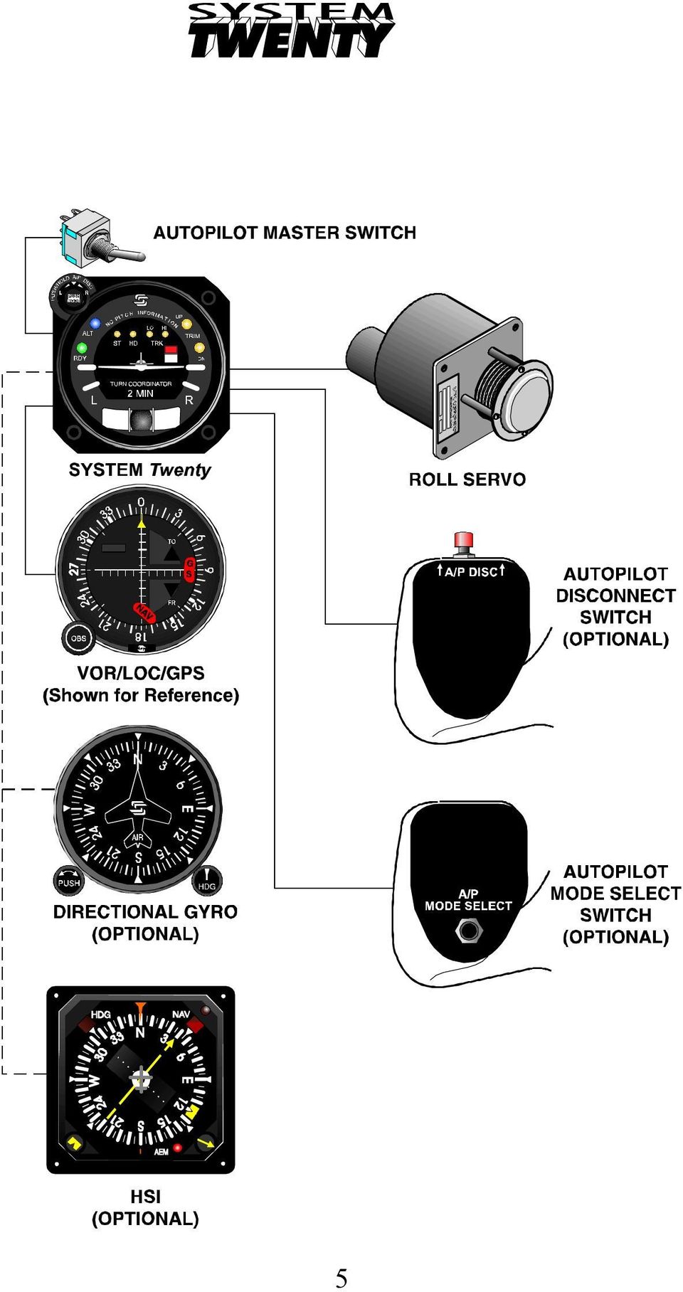
9 Twenty/Thirty/ThirtyALT System Twenty Modes of Operation PUSH MODE PUS H/HOLD A /P DISC RDY ALT I ST H I N F O U P LO HI TRIM HD TRK DN O L 2 MIN R 1. The System Twenty provides the aircraft with Roll Axis control only. 2. The Turn Coordinator contains the Roll Computer, Rate Gyro, Autopilot pick-off, Rate Gyro RPM detector, and an instrument power monitor that will flag if low system voltage occurs. 3. The System Twenty Turn Coordinator receives power through the battery buss and connects through an existing circuit breaker (CB) such that the basic Turn Coordinator function is powered on application of aircraft power. With adequate power applied, the Red Flag in the face of the unit fully retracts, indicating the Turn Coordinator function is operational. 4. A separately mounted On/Off panel switch and an A/P CB provides Integrated Roll Computer power. Power to the A/P CB can be supplied through the Avionics Master Switch. When activated a self-test is completed. The Functional Pre-Flight section contains this procedure. 5. The Rate Gyro is the basic sensor for roll stabilization. 9
 such that the basic Turn Coordinator function is powered on")
10 6. The Rate Gyro signal combines with, the Turn Command Knob, Heading Error Signal, or NAV inputs to generate a Roll Error signal, which then drives the roll servo as needed. 7. The System Twenty operates in one of four roll modes. The modes are Stabilizer, Heading, Low Track, and High Track, the latter two being navigation modes. 8. The green Ready (RDY) Light indicates the gyro has reached its operating RPM and the autopilot can be engaged. 9. The multi-functional Push Mode Select Knob, with each push, engages any one of the four autopilot modes sequentially. Depress and hold it until the A/P disconnects. PUSH MODE PUSH/HOLD A/P D ISC RDY ALT I ST H I NF O UP LO HI TRIM HD TRK DN O L 2 MIN R 10. In the Stabilizer Mode (ST), the Mode Select Knob, when centered, holds the wings level. When turned left or right it sends a proportional turn command to the roll servo. It activates the turn command for roll axis maneuvers up to 90% of a standard turn rate. The turn command function is inactive in HD, LO-TRK, and HI- TRK modes. 10

11 PUSH MODE PUSH/HOLD A /P DISC RDY ALT I ST H I N F O U P LO HI TRIM HD TRK DN O L 2 MIN R 11. Heading Mode requires an optional Directional Gyro (DG) or Horizontal Situation Indicator (HSI) with compatible outputs. The heading bug permits preselected heading turns and heading hold. If the System Twenty is not interfaced to an autopilot compatible DG or HSI the autopilot will by-pass this mode and advance to the "LO-TRK" mode. PUSH MODE PUS H/HOLD A /P DISC RDY ALT I ST H I N F O UP LO HI TRIM HD TRK DN O L 2 MIN R 12. LO-TRK Mode is primarily for VOR cross-country navigation. The low gain minimizes autopilot response to needle deviations. This will prevent over-correction in areas where low elevation or extreme distances from a VOR cause the needle to become noisy or have a scalloping effect. 11

12 PUSH MODE PUSH/HOLD A /P DISC RDY ALT I ST H I N F O UP LO HI TRIM HD TRK DN O L 2 MIN R 13. The HI-TRK Mode is designed for Localizer approaches, GPS/LORAN tracking, and a more aggressive NAV tracking such as VOR approaches. 14. The aircraft lighting rheostat controls the A/P systems light intensity. System Twenty Functional Preflight Procedures Note: There must be adequate aircraft DC voltage (14 or 28 Vdc) to perform these checks. Low voltage may adversely effect the Functional Preflight Procedures 1. Autopilot master switch "ON". RDY, ST, HD, LO TRK, and HI TRK lamps will temporarily illuminate on the annunciator panel. After 7 seconds, all lamps will be out. After 1-2 minutes the green "RDY" light illuminates indicating the autopilot can be engaged. 2. Press and release the Mode Select Knob, "ST" lamp illuminates. Rotate turn knob left then right, observe that the control wheel moves respectively. Center the Mode Select Knob. The control wheel should remain motionless. 12
 to perform these checks.")
13 3. Set the DG (if installed) and place heading bug under the Lubber line. Press and release the Mode Select Knob, "HD" lamp illuminates. Rotate heading bug left then right, observe the control wheel moves respectively. 4. Override Test, grasp the control wheel and slowly overpower the roll servo left and right to ensure proper clutch action. Caution: Control wheel movements should be smooth. If any unusual noise or feel occurs immediately inspect the installation and the clutch settings and repair as needed. Do not operate the Autopilot under these conditions. 5. Radio Check, tune the Nav radio to a valid VOR signal. Press and release Mode Select Knob, LO-TRK lamp illuminates. Move VOR OBS so the CDI needle moves left and right. Observe that the control wheel moves respectively. Press and release Mode Select Knob, HI- TRK lamp illuminates. Perform the same test. The control wheel response should be slightly faster in this mode. 6. Press and hold the Mode Select Knob until the A/P disconnects. Repeat this test using the optional control wheel mounted A/P disconnect switch, if installed. As the autopilot disconnects, the "RDY" light flashes with a five-second audible beeping tone. 13

14 System Twenty In Flight Procedures Stabilizer and Heading Mode 1. Check that the "RDY" light is ON. 2. Trim aircraft to desired flight conditions. 3. Center Mode Select Knob, press and release to engage the "ST" mode. 4. Set the Mode Select Knob as desired for level flight or turns. 5. Set the heading bug (if installed) to a desired heading, press and release the Mode Select Knob to engage "HD". VOR Tracking and VOR Approach Note: The System Twenty/Thirty does not provide intercept capability but will accurately track a reliable navigation signal when following one of these procedures listed below: 1. Tune the NAV receiver, verify a valid Nav Signal, and then select a Radial. 2. Set the A/P NAV select switch to the proper source, if so equipped. 3. Maneuver the aircraft to within +/ 1 needle width and within 10 HDG of the selected radial. 4. Press and release Mode Select Knob until LO-TRK lamp illuminates for VOR cross country or HI-TRK for VOR approaches and more sensitive tracking. 14

15 Localizer Approach 1. Tune the NAV receiver to the desired Localizer frequency. 2. Set A/P NAV select switch to proper source, if so equipped. 3. Maneuver the aircraft to within +/ 1 needle width and within 10 HDG of the published inbound localizer course. 4. Press and release Mode Select Knob until HI-TRK lamp illuminates. GPS Tracking and GPS Approach 1. Enter desired waypoint in GPS receiver. 2. Set A/P NAV select switch to proper source, if so equipped. 3. Maneuver the aircraft to within +/ 1 needle width and within 10 of the course displayed on the GPS receiver. 4. Press and release Mode Select knob until HI-TRK lamp illuminates. Note: This procedure is also applicable with Loran. Note: When flying multiple waypoints repeat steps 3 &4 for each leg if it involves more than a 10 course change. 15

16 Procedure Turn Localizer Approach and Tracking, Standard D.G N A. Tune navigation radio to LOC frequency. B. Set heading bug to published outbound LOC heading. Select HDG Mode. 2. A. Set heading bug to outbound procedure turn heading. 3. In 90 increments, set heading bug to inbound procedure turn heading. 4. A. Set heading bug to inbound LOC heading. B. Select the HI-TRK mode. Autopilot will track inbound to the airport. C. Once established in HI-TRK mode, set heading bug to the published missed approach heading. Note Before engaging HI-TRK be sure the aircraft is on course within ± 1 needle width and within ± 10 of HDG of the inbound course Note If a missed approach is declared at the middle marker: 2. A. Disconnect the autopilot and stabilize the aircraft for the missed approach. B. Select the HDG mode

17 Straight In Localizer Approach and Tracking, Standard D.G. 1. A. With HDG Mode selected, tune navigation radio to localizer frequency. B. With HDG bug, position aircraft on the Localizer inbound course. C. Select the HI-TRK mode. Autopilot will track inbound to the airport. D. Once established in HI-TRK mode, set heading bug to the published missed approach heading. Note Before engaging HI-TRK be sure the aircraft is on course within ± 1 needle width and within ± 10 of HDG of the inbound course Note If a missed approach is declared at the middle marker: 2. A. Disconnect the autopilot and stabilize the aircraft for the missed approach. B. Select the HDG mode. 17

18 Procedure Turn Localizer Approach and Tracking, Optional HSI N A. Tune navigation radio to LOC frequency. B. Set published inbound LOC course with course pointer. C. Set HDG bug to desired HDG for Localizer outbound. Press HDG mode switch. 3. Set HDG bug to published outbound procedure turn HDG. 4. A. In 90 increments, set heading bug to inbound procedure turn heading. B. When established on inbound course to the airport select HI-TRK mode. C. Once established in HI-TRK mode, set heading bug to the published missed approach heading. Note Before engaging HI-TRK be sure the aircraft is on course within ± 1 needle width and within ± 10 of HDG of the inbound course Note If a missed approach is declared at the middle marker: 2. A. Disconnect the autopilot and stabilize the aircraft for the missed approach. B. Select the HDG mode. 18

19 Straight In Localizer Approach and Tracking, Optional HSI 1. A. With the HDG Mode selected, tune navigation radio to LOC frequency. B. With the HDG bug, position the aircraft on the Localizer course. C. Select HI-TRK mode. The A/P will track inbound to the airport. D. Once established in HI-TRK mode, set heading bug to the published missed approach heading. Note Before engaging HI-TRK be sure the aircraft is on course within ± 1 needle width and within ± 10 of HDG of the inbound course Note If a missed approach is declared at the middle marker: 2. A. Disconnect the autopilot and stabilize the aircraft for the missed approach. B. Select the HDG mode. 19

20 System Thirty Modes of Operation Note: The Roll Axis is identical for the System Twenty and System Thirty. Refer to the System Twenty section for Roll Axis procedures. PUSH MODE PUSH/HOLD A/P DISC ALT I ST H I NF O UP LO HI TRIM HD TRK O RDY DN L 2 MIN R 1. The System Thirty incorporates an accelerometer and absolute pressure transducer as pitch rate sensors. 2. The Dynamic Acceleration, Vertical Speed, and Altitude Error Signals combine to obtain the Pitch Error Signal, which then drives the pitch servo as needed. 3. Altitude Hold Mode, the Altitude Hold light (blue), located above the green "RDY" light illuminates when Altitude Hold engages. 4. Trim Up light indicates the aircraft is out of trim nose down and requires elevator "UP" trim. 5. Trim Dn light indicates the aircraft is out of trim nose up and requires elevator "DOWN" trim. 6. With both lights out the aircraft is in trim. 7. The aircraft lighting rheostat controls the A/P systems light intensity PUSH MODE PUSH/HOLD A /P DISC RDY ALT I ST H I N F O U P LO HI TRIM HD TRK DN O L 2 MIN R 20

21 System Thirty Functional Preflight Procedures Note: Refer to the System Twenty Preflight for Roll Command checks. 1. Autopilot Master Switch "ON" 2. RDY, ST, HD, Lo Trk, HI-TRK, Trim-Up, Trim-Dn, Alt all annunciate. 3. Trim-Up light extinguishes after 2 seconds. 4. All others extinguish after 7 seconds except ALT, which extinguishes after 10 seconds. 5. Engage desired roll mode, move control wheel to the neutral position. 6. Select ALT mode by pressing and releasing the Remote Altitude Hold Eng/Dsng switch. The blue indicator light will illuminate. 7. Slowly apply forward pressure to the control wheel, "Trim- Up" light illuminates and alert tone is audible, release pressure. Light should go out and tone off. Note: Some aircraft have weights in the control system that may apply a FWD pressure when the controls are released. This keeps the "TRIM UP" light illuminated. Applying AFT pressure to the controls during this check will "Unload" this pressure on the system. 8. Slowly pull control wheel aft until the "Trim Down" light illuminates and alert tone is audible, return wheel to neutral. Light should go out and tone is off. 9. Press and release the Alt Hold Eng/Dsng switch, the blue indicator should go out. Verify disengagement of the pitch servo by moving the control wheel fwd and aft. 21
22 10. Press and hold the Mode Select switch until the A/P disconnects or the optional control wheel mounted A/P disconnect switch, if installed. The RDY light flashes, you should get an audible beeping tone for approximately five seconds. System Thirty In Flight Procedures Caution: If necessary, the required pre-flight test can be conducted in flight. However, during the power up test the pitch servo will engage and disengage to ensure that it will disengage during excessive "G" conditions. Therefore, do not attempt flight maneuvers during the power up test. Caution: If the pilot fails to trim the aircraft, the UP or DN trim light will annunciate with an audible alert tone. Within 4 seconds, the trim light will flash and the alert tone will beep. 1. Trim aircraft for level flight conditions, set power, and permit air speed to stabilize, then trim elevator as required. 2. Toggle "A/P" switch "ON"; verify green "RDY" light is illuminated after power on test terminates. 3. Select desired Roll Mode, verify light illuminates. 4. Engage Altitude Hold, verify "ALT" (Blue) indicator light illuminates. 5. Trim elevator according to light indication on the System Thirty controller. 6. In order to climb or descend, disengage the Altitude Hold. Note: If aircraft encounters turbulence, it is normal for the Trim Annunciator Lights to flicker. Elevator trim is only required if the trim Annunciator Light remains on and you hear an alert tone. Example: "Trim Up" indicates the need for nose up trim. The Aircraft is in trim when both lights are out. 22
23 System ThirtyALT Modes of Operation 1. The System ThirtyALT provides aircraft pitch axis control only. The System Thirty and ThirtyALT pitch computers are identical. 2. The Dynamic Acceleration, Vertical Speed, and Altitude Error Signals combine to obtain the Pitch Error Signal, which then drives the pitch servo as needed. 3. Green "ON" and "ALT" lights will illuminate when the ALT Hold switch is engaged on the ALT Hold Push ON/OFF panel. A yellow trim UP or DOWN light will illuminate and a steady audio alert will accompany the trim light after approximately five seconds. If the pilot fails to trim the aircraft, the UP or DN trim light will begin to flash accompanied by a beeping tone to emphasis a need for trim. Both lights are out the aircraft is in trim. 4. Altitude Hold Power comes through the master power switch for the ThirtyALT System. This switch must be ON before the "ALT Hold" switch will function. 5. The control wheel ALT Eng/Dsng switch is an optional switch that permits the pilot to engage or disengage the Altitude Hold from the control wheel, once the master switch has been powered up. 6. The aircraft lighting rheostat controls the A/P systems light intensity 23
24 System ThirtyALT Functional Preflight Procedures NOTE: There must be adequate aircraft DC voltage (14 or 28 Vdc) to perform these checks. 1. Each time the Altitude Hold power is switched on, the system will go through a self-test. All annunciator lights and the integral pitch accelerometer circuitry are tested during this time. The following should occur: a. All lights on the switch should illuminate. b. Trim UP light goes out. c. Trim DN light goes out. d. ALT and ON lights go out. e. The system is ready for engagement after approximately 15 seconds. Note: If the system test fails, the Altitude Hold cannot be engaged, and service is required. Caution: If necessary, the required pre-flight test can be conducted in flight. However, when the trim lights are flashing the pitch servo will momentarily engage and disengage as part of the test. Therefore, avoid flight maneuvers during the test. 2. Center the elevator control and engage the Altitude Hold. Notice that the pitch servo engages. 3. Slowly apply forward pressure on the control wheel, after three seconds the trim UP light illuminates with an audible tone. In approximately five seconds, the trim light flashes and audio beeps until the aircraft is trimmed. 4. Slowly apply aft pressure on the control wheel, after three seconds the trim DN light illuminates with an audible tone. 5. Disconnect the Altitude Hold by pressing the face of the Altitude Hold switch or by using the remote ALT Eng/Dsng switch (if installed) on the control wheel. 6. Verify that the pitch servo has disengaged by moving the control wheel Fwd and Aft. 24
25 System ThirtyALT In Flight Procedures 1. Maintain roll axis trim during Altitude Hold operation. 2. Trim aircraft for level flight conditions, set power, and permit air speed to stabilize, then trim elevator as required. 3. Engage ALT Hold by pushing the Altitude Hold switch or the remote ALT Eng/Dsng switch if installed on the control wheel. 4. Trim the elevator according to the trim light indications on the Altitude Hold annunciator panel. 5. Disengage the Altitude Hold for climb or descent modes of flight. Note: If aircraft encounters turbulence, it is normal for the Trim Annunciator Lights to flicker. Elevator trim is only required if the trim Annunciator Light remains on and you hear an alert tone Example: "Trim DN" indicates the need for nose down trim. The Aircraft is in trim with both lights out. Note: If using the ThirtyALT system as a stand alone A/P, without a Roll Axis system, do not use bank angles exceeding Thirty, excessive altitude losses may occur with the need to retrim the elevator. 25
26 Emergency Procedures If the aircraft, that has a System Twenty/Thirty/ThirtyALT installed, encounters any malfunctions with the A/P, follow the procedures below. This information is supplemental to and does not supercede or amend the information provided in the AFMS, POHS, SFM, for specific aircraft and autopilot installation manuals. If the aircraft does not have a copy of the required AFMS, please call customer service and S-TEC will provide a copy at no cost. Have the aircraft model and type of autopilot when calling for this supplement. 1. In case of an autopilot malfunction, do not attempt to diagnose the problem in flight. 2. Immediately regain manual control of the aircraft by overpowering the servo(s)and then disconnect the autopilot system. Note: The system includes a friction override clutch and a disconnect device at each Servo for that purpose. Overpowering the Servo will not damage the system. 3. To disconnect the Autopilot, use one of the following means. Press and release the remote AP disconnect switch on the control wheel (if installed). Press and hold the Mode Select Knob (System Twenty/Thirty only) on the Turn Coordinator/Roll Computer. Move the autopilot master switch to "Off." Pull the autopilot circuit breaker. 26
27 4. If improper operation occurs during an instrument approach condition, disconnect the system and fly a manual approach. If a failure occurs inside the final approach fix, it may be desirable to conduct a missed approach, notify Air Traffic Control (ATC) of the problem and fly the approach manually, seeking ATC's assistance as necessary. 5. If a particular mode of operation, including ALT Hold, develops a fault peculiar to that mode only, it is satisfactory to operate the system in other modes as long as a determination can be made as to their satisfactory function. 27
28 Specifications System Twenty/Thirty/ThirtyALT Turn Coordinator/Roll Computer Power required Flag Voltage Detector limits Flag RPM Detector limits Current requirements Weight Dimensions TSO Directional Gyro Power required Minimal air flow Air filtration Autopilot pickoff Weight Dimensions Internal lights Roll Servo Power required Current requirements Weight Dimensions TSO Pitch Computer Power required Weight Dimensions TSO 14/28 Vdc 9.0Vdc (approx.) Normal RPM <20% 0.3 Amp 2.2 lbs x 3.28 x 7.4 in. C3d, C9c Vacuum or pressure, Hg 2.2 CFM 3 Micron, 95% AC, linear transformer, 5kHz, 8 Vac (pp) supplied by autopilot. 3.4 lbs x 3.38 x 8.35 in. 14/28 Vdc 14/28 Vdc Included in system requirements 2.9 lbs x 3.75 x 7.25 in. C9c 14/28 Vdc 1.1 lbs. 5.8 x 1.75 x 3.25 in. C9c 28
29 Absolute Pressure Transducer Power required Pressure range Overpressure Weight Pitch Servo Power required Current required Weight Dimensions TSO 10 Vdc, 0-15 PSI Absolute 150% of operating maximum 0.2 lbs. 14/28 Vdc Included in system requirements 2.9 lbs x 3.75 x 7.25 in. C9c System Current Requirements Average operating current. Twenty/Thirty/ ThirtyALT 1.0 Amps/0.5 Amps Max current Twenty 3.0 Amps/2.0 Amps Thirty 5.0 Amps/3.0 Amps ThirtyALT 3.0 Amps/2.0 Amps 29
30 S-TEC Corporation One S-Tec Way Municipal Airport Mineral Wells, Texas USA Telephone 940/ ; FAX 940/ USA-STEC s-tec.com The information in this publication is subject to change without notice. P/N: 8777 Rev. A Date: 2 February, 1999 Printed in USA 30
Revision Number Revision Date Insertion Date/Initials 1 st Ed. Feb 01, 00 2 nd Ed. Jun 24, 02 3rd Ed. Feb 15, 07
 List of Effective Pages * Asterisk indicates pages changed, added, or deleted by current revision. Retain this record in front of handbook. Upon receipt of a Record of Revisions revision, insert changes
S-Tec System Thirty Autopilot
 Cirrus Design Section 9 Pilot s Operating Handbook and FAA Approved Airplane Flight Manual Supplement for S-Tec System Thirty Autopilot When the S-Tec System Thirty Autopilot is installed in the Cirrus
S TEC. List of Effective Pages. Record of Revisions
 List of Effective Pages * Asterisk indicates pages changed, added, or deleted by current revision. Retain this record in front of handbook. Upon receipt of a Record of Revisions revision, insert changes
Global Positioning System Steering (GPSS) Converter Pilot s Operating Handbook
 Converter Pilot s Operating Handbook") Global Positioning System Steering (GPSS) Converter Pilot s Operating Handbook List of Effective Pages * Asterisk indicates pages changed, added, or deleted by revision. Retain this record in front of
Global Positioning System Steering (GPSS) Converter Pilot s Operating Handbook List of Effective Pages * Asterisk indicates pages changed, added, or deleted by revision. Retain this record in front of
Revision Number Revision Date Insertion Date/Initials 1 st Edition February 1992 2 nd Edition March 05, 2002
 GPS List of Effective Pages * Asterisk indicates pages changed, added, or deleted by revision. Record of Revisions Retain this record in front of handbook. Upon receipt of a revision, insert changes and
CENTURY III AUTOPILOT FLIGHT SYSTEM
 CENTURY III AUTOPILOT FLIGHT SYSTEM PILOT S OPERATING HANDBOOK NOVEMBER 1998 68S25 NOTICE 68S25 This manual contains General Information on operation of Century III Autopilot. specific FAA approved information
G1000 Search Patterns. National Emergency Services Academy Mission Aircrew School (June 2013 Rev D)
") G1000 Search Patterns National Emergency Services Academy Mission Aircrew School (June 2013 Rev D) Standardized Visual Search Pattern method Visual search pattern techniques include: Minimum # of user
G1000 Search Patterns National Emergency Services Academy Mission Aircrew School (June 2013 Rev D) Standardized Visual Search Pattern method Visual search pattern techniques include: Minimum # of user
For Microsoft Flight Simulator X 2008 FriendlyPanels. All right reserved
 FriendlyPanels Software For Microsoft Flight Simulator X 2008 FriendlyPanels. All right reserved REPLACEMENT NAVIGATION GAUGES FOR FSX AIRCRAFT 1 1. Introduction. 2. Requirements 3. Installing the pack
Automated Flight Control
 Chapter 4 Automated Flight Control Introduction This chapter introduces automated flight control in the advanced avionics cockpit. You will learn to use an autopilot system that can significantly reduce
B777. Automatic Flight DO NOT USE FOR FLIGHT
 B777 Automatic Flight DO NOT USE FOR FLIGHT 4.10 Automatic Flight-Controls and Indicators Mode Control Panel (MCP) A/T ARM L R IAS MACH HDG TRK V/S FPA ALTITUDE A/P F/D ON OFF CLB CON IAS LNAV VNAV AUTO
Airglas, Inc. MANUAL NO. GLH3000-105-AHSA. MODEL GLH3000 Ski Kit Actuated by Wipaire, Inc. Amphibious Float Hydraulic System
 Airglas, Inc. Amphibious hydraulic system addendum to Instructions for Continued Airworthiness Including Installation, Maintenance and Service Instructions MANUAL NO. GLH3000-105-AHSA MODEL GLH3000 Ski
Cessna 172SP & NAV III Maneuvers Checklist
 Cessna 172SP & NAV III Maneuvers Checklist Introduction Power Settings This document is intended to introduce to you the standard method of performing maneuvers in Sunair Aviation s Cessna 172SP and NAV
LOG OF REVISIONS Revision Page FAA Date of Number Number(s) Description Approved Approval A All Initial Release K.
 Description Approved Approval A All Initial Release K.") LOG OF REVISIONS Revision Page FAA Date of Number Number(s) Description Approved Approval A All Initial Release K. Campbell* 4/4/00 B 5, 10 Remove SKYWATCH and add GTX 330 TIS G. Baker* 11/21/02 C All
LOG OF REVISIONS Revision Page FAA Date of Number Number(s) Description Approved Approval A All Initial Release K. Campbell* 4/4/00 B 5, 10 Remove SKYWATCH and add GTX 330 TIS G. Baker* 11/21/02 C All
737 NG Comm unications
 B737 NG Comm munications 5.20 Communications-System Description Introduction The communication system includes: radio communication system interphone communication system cockpit voice recorder system
09 FLIGHT MANAGEMENT, NAVIGATION
 Course overview N E X T G E N E R A T I O N Airplane General Air Systems Warning Systems, Communications, Ice & Rain Protection Electrical Engines, APU, Fuel System Hydraulics, Flight Controls, Landing
The KFC 225 s Internal GPSS. by Dan Herr, TTCF Member. November 2014
 The KFC 225 s Internal GPSS by Dan Herr, TTCF Member November 2014 The KFC 225 was designed after the advent of aviation GPS, but before WAAS and before GPS approaches had a glideslope. Unlike VOR navigation,
GNS 430/430A. Quick Reference
 GNS 430/430A Quick Reference KEYS AND KNOBS 1 2 3 4 5 6 7 8 9 10 11 12 13 14 15 16 17 18 1 COM Power/Volume 7 RNG (map range) 13 OBS 2 VLOC Volume 8 MENU 14 MSG (message) 3 COM Flip-flop 9 ENT (enter)
AMI MARINE (UK) LTD BRIDGE NAVIGATIONAL WATCH ALARM SYSTEM (BNWAS) Operation Manual KW810
 LTD BRIDGE NAVIGATIONAL WATCH ALARM SYSTEM (BNWAS) Operation Manual KW810") AMI MARINE (UK) LTD BRIDGE NAVIGATIONAL WATCH ALARM SYSTEM (BNWAS) Operation Manual KW810 This Manual and the information contained therein is the property of AMI Marine (UK) Ltd. It must not be reproduced
AMI MARINE (UK) LTD BRIDGE NAVIGATIONAL WATCH ALARM SYSTEM (BNWAS) Operation Manual KW810 This Manual and the information contained therein is the property of AMI Marine (UK) Ltd. It must not be reproduced
Multi Engine Oral Exam Questions
 Multi Engine Oral Exam Questions 1. What are the requirements for a multi-engine rating? 2. What is the max rated horse power at sea level? At 12,000 msl? 3. What is the rated engine speed? 4. What is
2014 NIFA CRM Contestant Briefing Guide San Diego, California
 2014 NIFA CRM Contestant Briefing Guide San Diego, California Region 2 SAFECON 2014 November 12 15 This document supports the 2014 NIFA Collegiate Cockpit Resource Management Simulation and is not for
KX 155A and KX 165A VHF Communication/Navigation Transceivers
 KX 155A and KX 165A VHF Communication/Navigation Transceivers KX 155A and KX 165A Operation (25 khz Versions) KX 155A/165A All controls required to operate the KX 155A and KX 165A are located on the unit
MK12D TSO (MK12, MK12A, MK12B REPLACEMENT RADIO)
") NARCO AVIONICS MK12D TSO (MK12, MK12A, MK12B REPLACEMENT RADIO) ADDENDUM INSTALLATION MANUAL 03118-0620R NARCO AVIONICS INC. 270 COMMERCE DRIVE FT. WASHINGTON, PA. 19034 U.S.A. PRINTED IN U.S.A. JUNE,
NARCO AVIONICS MK12D TSO (MK12, MK12A, MK12B REPLACEMENT RADIO) ADDENDUM INSTALLATION MANUAL 03118-0620R NARCO AVIONICS INC. 270 COMMERCE DRIVE FT. WASHINGTON, PA. 19034 U.S.A. PRINTED IN U.S.A. JUNE,
Aviation Safety Prize ecfi Tasks
 2008 NASA "The PAV Challenge" Aviation Safety Prize ecfi Tasks The Aviation Safety Prize (ASP) will be based upon a set of defined tasks that can be flight demonstrated to the CAFE Test Pilots by each
Global Avionics Training Specialists, LLC.
 Global Avionics Training Specialists, LLC. PRIMUS 2000/DORNIER 328 JET INTEGRATED AVIONICS SYSTEM LINE MAINTENANCE FAMILIARIZATION COURSE SYLLABUS I. INTRODUCTION A. SYSTEM DESCRIPTION The PRIMUS 2000
BOMBARDIER CRJ700. Bombardier CRJ700 Aircraft Reference
 Bombardier CRJ700 Aircraft Reference V 1 Takeoff Decision Speed, dry runway 50,000 lbs, (flaps 8) 144 KIAS 50,000 lbs, (flaps 20) 134 KIAS V R Rotation Speed, dry runway 50,000 lbs, (flaps 8) 144 KIAS
VEHICLE SPEED CONTROL SYSTEM
 PL VEHICLE SPEED CONTROL SYSTEM 8H - 1 VEHICLE SPEED CONTROL SYSTEM TABLE OF CONTENTS page DESCRIPTION AND SPEED CONTROL SYSTEM...1 SPEED CONTROL SERVO-PCM OUTPUT....2 SPEED CONTROL SWITCHES PCM INPUT...2
P/N 135A-970-022 FAA Approved: 12/6/2007 Section 9 Initial Release Page 1 of 8
 FAA APPROVED AIRPLANE FLIGHT MANUAL SUPPLEMENT FOR GARMIN SL40 NAV/COMM Serial No: Registration No: When the GARMIN SL40 COM radio is installed in the Liberty Aerospace XL-2, this supplement is applicable
0 28 November 2011 N/A First Release of Manual 1 24 February 2012 Page 21 Error in FY31AP connection diagram corrected.
 Rev 1: 24 February 2012 FEIYU TECH FY31AP Autopilot System Installation & Operation Guide Guilin Feiyu Electronic Technology Co., Ltd Rm. B305, Innovation Building, Information Industry Park, Chaoyang
ENGINE FIRE / SEVERE DAMAGE / SEPARATION ON TAKEOFF
 ENGINE FIRE / SEVERE DAMAGE / SEPARATION ON TAKEOFF According to RYANAIR Procedures PF PM REMARKS Control the aircraft (FULL T/O thrust can be manually selected) Announce «ENGINE FAILURE» or «ENGINE FIRE»
INSTRUCTION MANUAL. Specification: collective pitch 3D quadcopter. TYPE: Collective Pitch Electric 3D Quadcopter. Rotor Diameter: 118MM.
 collective pitch 3D quadcopter INSTRUCTION MANUAL Specification: TYPE: Collective Pitch Electric 3D Quadcopter Rotor Diameter: 118MM Length:635 MM Width: 365 MM Weight: 986g w/out battery Flying weight
WHICH AIR TRAFFIC CONTROLLER TO CONTACT
 WHICH AIR TRAFFIC CONTROLLER TO CONTACT 1. Introduction This article is written in order to explain to all beginners in the IVAO network the basics for any pilot to contact the correct air traffic controller.
INSTALLATION MANUAL AND OPERATING INSTRUCTIONS. 4300-XXX Series Electric Attitude Indicator With Battery Backup
 INSTALLATION MANUAL AND OPERATING INSTRUCTIONS 4300-XXX Series Electric Attitude Indicator With Battery Backup Mid-Continent Instruments and Avionics Manual Number 9015762 9400 E 34 th Street N, Wichita,
Automation at Odds. A 737 stalled when a radio altimeter malfunction caused the autothrottle and autopilot to diverge during an approach to Schiphol.
 Automation at Odds The pilots of a Boeing 737-800 did not heed indications of a significant decrease in airspeed until the stick shaker activated on final approach to Runway 18R at Amsterdam (Netherlands)
LANDING GEAR & BRAKES www.theaviatornetwork.com GTM 14.1 2005 1-30-05 CONTENTS INTRODUCTION... 14.2
 www.theaviatornetwork.com GTM 14.1 CONTENTS INTRODUCTION... 14.2 GENERAL... 14.2 MAIN LANDING GEAR... 14.2 Landing Gear Latch Lever and Handle... 14.2 Landing Gear Pressure Gauge... 14.2 Landing Gear Warning
FLIGHT CONTROLS 1. GENERAL 2. MAIN COMPONENTS AND SUBSYSTEMS ROLL CONTROL. Smartcockpit.com BOEING 737 SYSTEMS REVIEW Page 1
 Smartcockpit.com BOEING 737 SYSTEMS REVIEW Page 1 FLIGHT CONTROLS 1. GENERAL The primary flight controls, ailerons, elevators and rudders, are hydraulically powered. Hydraulic power is provided from hydraulic
B777. Landing Gear DO NOT USE FOR FLIGHT
 B777 Landing Gear DO NOT USE FOR FLIGHT Introduction The airplane has two main landing gear and a single nose gear. The nose gear is a conventional steerable two wheel unit. Each main gear has six wheels
Cessna 172S. Flight Training Standardization Guide REVISION: ORIGINAL
 Cessna 172S Flight Training Standardization Guide REVISION: ORIGINAL Contents Purpose... 4 Normal and Crosswind Takeoff and Climb... 5 Normal and Crosswind Landing... 6 Soft Field Takeoff and Climb...
VFR Day Emergencies - C172R
 Pilot Level: References: Note: VFR Day Emergencies - C172R Student Pilot. FAA-H-8083-3A, Chapter 16, Federal Aviation Regulations, Cessna 172R PIM, Aeronautical Information Manual, King Schools (DVDs):
Primus 880 Weather Radar. Reliable Weather Avoidance Radar
 Primus 880 Weather Radar Reliable Weather Avoidance Radar Honeywell, the world s leader in avionics continues the development of weather radar systems with the Primus 880 featuring 10 kilowatts of transmitter
162 CB CABLE TRACER. Filter Probe & Tone Generator INSTRUCTION MANUAL
 162 CB CABLE TRACER Filter Probe & Tone Generator INSTRUCTION MANUAL INDEX PAGE 1. INTRODUCTION... 1 2. FILTER PROBE... 1-3 3. TONE GENERATOR... 3-6 4. SPECIFICATION... 7-8 5. MAINTENANCE... 8 1. INTRODUCTION
VHF COMMUNICATION TRANSCEIVER
 ATR-500 VHF COMMUNICATION TRANSCEIVER ON OFF OPERATION MANUAL Manual Number 01.125.010.08 REVISION 1.3, Jan 20. 2005 from S/N 00301 04 Contents 1 SECTION 1 GENERAL INFORMATION...3 1.1 INTRODUCTION...3
The SeaRey - An Introduction
 The SeaRey - An Introduction Welcome to the beautiful Progressive Aerodyne SeaRey. The SeaRey is a very special aircraft. Created by a small team of engineers the SeaRey is perhaps the ultimate kit built
Manual for Fire Suppression & Methane Detection System
 Manual for Fire Suppression & Methane Detection System Fogmaker North America Post address: 150 Gordon Dr Exton, PA 19341 Delivery address: 150 Gordon Dr Exton, PA 19341 Tel: 610-265-3610 Fax: 610-265-8327
EFIS-D100 Electronic Flight Information System
 EFIS-D100 Electronic Flight Information System Pilot s User Guide P/N 100477-000, Revision H For use with firmware version 5.4 August, 2010 Dynon Avionics This product is not approved for installation
Servo Info and Centering
 Info and Centering A servo is a mechanical motorized device that can be instructed to move the output shaft attached to a servo wheel or arm to a specified position. Inside the servo box is a DC motor
AC-115 Compact Networked Single Door Controller. Installation and User Manual
 AC-115 Compact Networked Single Controller Installation and User Manual December 2007 Table of Contents Table of Contents 1. Introduction...5 1.1 Key Features... 6 1.2 Technical Specifications... 7 2.
Light Sport West Standard Flight Training Procedures for N110GX (Remos GX, 100 H.P.)
") Light Sport West Standard Flight Training Procedures for N110GX (Remos GX, 100 H.P.) Welcome to Light Sport West! Thank you for giving us the opportunity to provide all of your flight training needs. Our
Light Sport West Standard Flight Training Procedures for N110GX (Remos GX, 100 H.P.) Welcome to Light Sport West! Thank you for giving us the opportunity to provide all of your flight training needs. Our
Electronic Brake Controller Hayes Brake Controller Company ENERGIZE III P/N # 81741B or ENERGIZE XPC P/N #81745 OPERATION MANUAL
 Electronic Brake Controller Hayes Brake Controller Company ENERGIZE III P/N # 81741B or ENERGIZE XPC P/N #81745 OPERATION MANUAL ENERGIZE III is for trailers with 2 or 4 electric brakes and vehicles with
12 AERO Second-Quarter 2003 April CAPT. RAY CRAIG 737 CHIEF PILOT FLIGHT OPERATIONS BOEING COMMERCIAL AIRPLANES
 CAPT. RAY CRAIG 737 CHIEF PILOT FLIGHT OPERATIONS BOEING COMMERCIAL AIRPLANES DREW HOUCK ASSOCIATE TECHNICAL FELLOW FLIGHT DECK DISPLAYS BOEING COMMERCIAL AIRPLANES ROLAN SHOMBER ASSOCIATE TECHNICAL FELLOW
FLIGHT TRAINING (AEROPLANE) BASED ON JAR FCL - PPL(A) FLIGHT INSTRUCTION Syllabus
 BASED ON JAR FCL - PPL(A) FLIGHT INSTRUCTION Syllabus") FLIGHT TRAINING (AEROPLANE) BASED ON JAR FCL - PPL(A) FLIGHT INSTRUCTION Syllabus for MARSPOLAR, DUBAI UAE Exercise 1 Familiarisation with the aeroplane characteristics of the aeroplane cockpit layout
FLIGHT TRAINING (AEROPLANE) BASED ON JAR FCL - PPL(A) FLIGHT INSTRUCTION Syllabus for MARSPOLAR, DUBAI UAE Exercise 1 Familiarisation with the aeroplane characteristics of the aeroplane cockpit layout
Bombardier Challenger 605 - Communications
 GENERAL The aircraft communication system includes those components and subsystems providing air-to-ground, interphone and cabin communications. The system is also responsible for recording communications
INSTALLATION MANUAL KCS 55/55A PICTORIAL NAVIGATION SYSTEM
 INSTALLATION MANUAL KCS 55/55A PICTORIAL NAVIGATION SYSTEM MANUAL NUMBER 006-00111-0010 REVISION 10 FEBRUARY 2002 WARNING Prior to the export of this document, review for export license requirement is
WD-AMX Water Detection Controllers
 Page 1 of 5 WD-AMX Water Detection Controllers Features: Benefit: LED Status of leak status VFC output Audible alarm Auto or manual reset alarm output Uses an isolated AC signal which prevents oxidation
Owner's Copy. 104873 December 14, 2011 ELECTRICAL INSTRUCTIONS FOR ADVANTEX EA OR EX MODELS
 104873 December 14, 2011 Detex Corporation, 302 Detex Drive, New Braunfels, Texas 78130-3045 (830)629-2900 / 1-800-729-3839 / Fax (830)620-6711 E-MAIL: [email protected] INTERNET: www.detex.com ELECTRICAL
Date: 07/20/07 Initiated by: AFS-800
 Advisory Circular Subject: Use of Class 1 or Class 2 Electronic Flight Bag (EFB) Date: 07/20/07 Initiated by: AFS-800 AC No: 91-78 1. PURPOSE. This advisory circular (AC) provides aircraft owners, operators,
Owner s Manual AWM910 JENSEN AWM910 COMPACT DISC PLAYER RADIO CD COMPACT MUSIC SYSTEM MUTE AUX BAND AUX IN PUSH PUSH PWR VOL ALARM T/F AUD SPK A SPK B
 AWM910 Owner s Manual COMPACT DISC PLAYER PUSH 1 2 3 4 5 6 RPT SCAN RDM H M PUSH PWR VOL ALARM SET ON/OFF EQ T/F AUD RADIO CD COMPACT MUSIC SYSTEM MUTE AUX BAND CD AUX IN A B A+B JENSEN AWM910 Thank You!
MEMO AIRBUS A319/A320/A321. SOP / Flow Pattern
 MEMO AIRBUS A319/A320/A321 SOP / Flow Pattern F/O side only ( or ) A320 Flow Pattern SOP Visual Pattern Engine Out Memory Items Emergency procedures Laurent ALAPHILIPPE Page 1/18 Année 2011 Summary Memo
The Dramatic Effects of Pitot-Static System Blockages and Failures. References... 51
 The Dramatic Effects of Pitot-Static System Blockages and Failures by Luiz Roberto Monteiro de Oliveira. Table of Contents I II III IV V VI Introduction.1 Pitot Static Instruments..3 Blockage Scenarios
King Air C90A. Speeds (KIAS)
") King Air C90A Speeds (KIAS) V MCA 90 V SSE 97 V X 101 V Y 111 V XSE 100 V YSE 107 V A 169 V REF 100 V MO 208 V FE 178 35% 137 100% V LE 156 129 Retraction only Other 95 Balked landing climb 125 Glide 161
King Air C90A Speeds (KIAS) V MCA 90 V SSE 97 V X 101 V Y 111 V XSE 100 V YSE 107 V A 169 V REF 100 V MO 208 V FE 178 35% 137 100% V LE 156 129 Retraction only Other 95 Balked landing climb 125 Glide 161
DIGITAL ALARM II FOR HOSPITALS AND LABORATORIES INSTALLATION AND OPERATING INSTRUCTIONS 52 635.0
 Form No. 74-00-4001 S168-195-001 Revision E DIGITAL ALARM II FOR HOSPITALS AND LABORATORIES INSTALLATION AND OPERATING INSTRUCTIONS 52 635.0 INTRODUCTION Allied Healthcare Products, Inc. s Digital Alarm
Residential Gateway (RG) Battery Backup
 Battery Backup") Residential Gateway (RG) Battery Backup BU3DC000-12V User Manual Table of Contents Page Introduction... 3 Safety Information... 3 System Requirements... 3 Package Contents... 4 Recycling... 4 Product Layout
Residential Gateway (RG) Battery Backup BU3DC000-12V User Manual Table of Contents Page Introduction... 3 Safety Information... 3 System Requirements... 3 Package Contents... 4 Recycling... 4 Product Layout
Honeywell Primus HF 1050 HF Radio System
 Honeywell Primus HF 1050 HF Radio System 1 HF Technical Description Honeywell s new 28Vdc HF radio advances the performance and capability of our HF systems to meet the emerging needs of the HF market
BACK PRESSURE MONITOR Operator Display with Exhaust Temperature KIT 194-722
 HEWITT INDUSTRIES 5492 BOLSA AVE. HUNTINGTON BEACH, CA 92649 PH. (714) 891-9300 FAX. (714) 897-7632 WEBSITE: www.hewittindustries.com E-MAIL: [email protected] BACK PRESSURE MONITOR Operator Display
ENGINEERING RELEASE MODEL: LEARJET MODEL 20 AND 35/36 SERIES DRAWING. NO.: 02907011 SHEET: 1 OF 1
 ENGINEERING RELEASE DRAWING. NO.: 02907011 MODEL: LEARJET MODEL 20 AND 35/36 SERIES SHEET: 1 OF 1 Butler National Corporation Olathe, Kansas DRAWING TITLE: INSTRUCTIONS FOR CONTINUED AIRWORTHINESS FOR
COMMUNICATIONS GROUND COMMUNICATIONS OUTLET (GCO)
") 388 COMMUNICATIONS GROUND COMMUNICATIONS OUTLET (GCO) An automatic, remotely controlled, ground to ground communications device. Pilots at non-tower airports may contact the local Air Traffic Control (ATC)
388 COMMUNICATIONS GROUND COMMUNICATIONS OUTLET (GCO) An automatic, remotely controlled, ground to ground communications device. Pilots at non-tower airports may contact the local Air Traffic Control (ATC)
ABC-1000 Automatic Boiler Level Controller Operation and Installation Manual
 QUALITY STEAM SPECIALTIES SINCE ABC-1000 Automatic Boiler Level Controller Operation and Installation Manual Section: C500 Bulletin: C500.40 Date: 06-26-01 Supersedes: New PRODUCT DESCRIPTION: The Clark-Reliance
Municipal Airport 1410 Arizona Place S.W. Orange City, IA 51041-7453. www.angelaircraft.com [email protected] 712.737.3344
 Municipal Airport 1410 Arizona Place S.W. Orange City, IA 51041-7453 www.angelaircraft.com [email protected] 712.737.3344 PERFORMANCE SPECIFICATIONS POWERPLANT PROPELLER Lycoming IO-540 300 HP @2700
Instrument Pilot Rating Course (ASEL) Training Syllabus FAR Part 61
 Training Syllabus FAR Part 61") Instrument Pilot Rating Course (ASEL) Training Syllabus FAR Part 61 Property of Tech Aviation Flight School. Reproduction of this manual in full or part is strictly prohibited by law. Distribution or use
Instrument Pilot Rating Course (ASEL) Training Syllabus FAR Part 61 Property of Tech Aviation Flight School. Reproduction of this manual in full or part is strictly prohibited by law. Distribution or use
How to read this guide
 How to read this guide The following shows the symbols used in this Quick start guide with descriptions and examples. Symbol Description Example P oint Reference Caution [ ] This symbol explains information
Assessment Specifications for Remotely Piloted Aircraft Systems, Class 1 AS-RPAS1
 AMC Civil Aviation Authority The Netherlands Assessment Specifications for Remotely Piloted Aircraft Systems, Class 1 AS-RPAS1 Version 1.1 1 December 2014-1 - CONTENTS (general layout) AS RPAS1 REMOTELY
AMS 2000, ALTITUDE ALERT SYSTEM
 PRODUCT P/N: 8900 REV M Shadin Avionics 6831 Oxford Street St. Louis Park, MN 55426 USA Sales: (800)-328-0584 Technical Support: (800)-388-2849 www.shadin.com MANUAL P/N: IN8900A Rev M P/N 8900 Page i
POWER TRIM 5 F AUTO TRIM AND AUTO TRIM
 POWER TRIM 5 F 22217 AUTO TRIM AND AUTO TRIM Table of Contents Page Auto Trim System........................ 5F-1 Description........................... 5F-1 Auto Trim Operation...................... 5F-2
CYCLOPS OSD USER MANUAL 5.0
 CYCLOPS OSD USER MANUAL 5.0 Thank you for choosing CYCLOPS OSD V5.0 New features: CYCLOPS OSD V5.0 is incorporated with Autopilot function and infrared attitude sensor capable of controlling aircraft's
VARIABLE STABILITY FLIGHT OPERATIONS MANUAL
 SPACE INSTITUTE VARIABLE STABILITY FLIGHT OPERATIONS MANUAL Prepared by the Aviation Systems and Flight Research Department September 2004 Index 1.1 General Description...1 1.2 Variable Stability System...5
Avionics Can Give a Helping Hand
 COMMENTARY / LEFT SEAT Avionics Can Give a Helping Hand New systems from Garmin and Avidyne help pilots avoid the really big mistake An airplane that can safely fly itself at least when the pilot s attention
Bombardier Challenger 605 - Air Conditioning & Pressurization
 GENERAL The air conditioning system provides temperature-regulated, conditioned air to the cockpit and passenger cabin using two air conditioning units (ACU s), commonly referred to as packs. An electric
For Flight Simulation purposes only on the VATSIM Network.
 Compiled by Daniel A. Hawton, ZDC Training Administrator For Flight Simulation purposes only on the VATSIM Network. Introduction The goal of the document is to introduce you, the controller, to the appropriate
TMS TANK MANAGEMENT SYSTEM
 TMS TANK MANAGEMENT SYSTEM Page 1 of 9 Operating Instructions GENERAL The Tank Management System is a bespoke design to control, monitor and accommodate efficient storage and dispensing of TMS. FUNCTIONS
ER-1 Emergency Response System INSTALLATION & PROGRAMMING GUIDE
 Emergency Response System INSTALLATION & PROGRAMMING GUIDE Copyright micron 2005 Contents Product Description 3 Console Operation Overview 4 Console Wiring Diagram 5 User Manual 6 Transmitter Assembly
This section includes performance data on the King Air B200. Information consists of:
 King Air B200 POH Pilot's Operating Handbook: This section includes performance data on the King Air B200. Information consists of: 1. Critical Airspeeds 2. Operating NOTAMS 3. Fuel Loading Formula Checklists:
SMART SENSOR COLLECTION
 TEMPERATURE SENSOR This sensor measures temperature in degrees Celsius or Fahrenheit. It works with all SensorHawk base units (SensorHawk-2, SensorHawk-8 and SensorHawk8/20) as well as the SecurityHawk-8
Installation and Operation Back-UPS 1250, 1300, 1500
 Installation and Operation Back-UPS 1250, 1300, 1500 Inventory bu001a Safety and General Information This unit is intended for indoor use only. Do not operate this unit in direct sunlight, in contact with
Back-UPS Pro 1300/1500 Installation and Operation
 Back-UPS Pro 1300/1500 Installation and Operation Inventory Safety Do not install the Back-UPS in direct sunlight, in excessive heat, humidity, or in contact with fluids. Connect the battery bu059a bu058a
Using your LED Plus keypad
 Using your LED Plus keypad System 238 System 2316 System 238i System 2316i Part Number 5-051-372-00 Rev B Thank you for purchasing this C&K alarm system Your system is one of the most powerful and advanced
MGL Avionics Compass operation and calibration
 MGL Avionics Compass operation and calibration Page 1 Table of Contents General...3 Inside a MGL SP-6 compass...3 Compass modes...4 Compass mode 2 (3D accel)...4 Compass mode 4 (3D EFIS)...4 Other compass
Details of Candidate. Test/check details. Date of test 1 (dd/mm/yyyy) Date of test 2 (dd/mm/yyyy) Training certificate from manufacturer
 Date of test 2 (dd/mm/yyyy) Training certificate from manufacturer") Section/division: Aviation Personnel Standards Form Number: CA 101-03.3 Telephone number: 011-545-1000 Fax Number: 011-545-1459 Physical address: Ikhaya Lokundiza, 16 Treur Close, Waterfall Park, Bekker
Section/division: Aviation Personnel Standards Form Number: CA 101-03.3 Telephone number: 011-545-1000 Fax Number: 011-545-1459 Physical address: Ikhaya Lokundiza, 16 Treur Close, Waterfall Park, Bekker
Electronic Power Control
 Service. Self-Study Programme 210 Electronic Power Control Design and Function With the Electronic Power Control system, the throttle valve is actuated only by an electric motor. This eliminates the need
Guardian 2D/3D Stabilizer. Document Version 2.0 Assembled in Taiwan
 Guardian 2D/3D Stabilizer Document Version 2.0 Assembled in Taiwan Introduction Thank you for your purchase! Based on Eagle Tree's proven inertial stabilization technology, the Guardian 2D/3D Stabilizer
VBAR NEO. Quick Start Guide Express-Firmware
 VBAR NEO Quick Start Guide Express-Firmware Welcome to VBar NEO! VBar NEO is an innovative product setting new standards for model helicopters in terms of flight performance and programming capacity. Features:
harbor cub Electric Remote Control Airplane Model 92906 assembly & Operating Instructions
 harbor cub Electric Remote Control Airplane Model 92906 assembly & Operating Instructions IMPORTANT: If damage is caused due to a crash, your warranty is void. Visit our website at: http://www.harborfreight.com
TOTALLY SOLID STATE NON-DIRECTIONAL RADIO BEACONS 190-535 khz
 TOTALLY SOLID STATE NON-DIRECTIONAL RADIO S 190-535 khz This family of radio transmitters has been developed as extremely efficient, highly reliable Non Directional Beacons. ND2000A/4000A» MODULAR CONSTRUCTION»
T7560A,B,C Digital Wall Module
 T7560A,B,C Digital Wall Module HONEYWELL EXCEL 5000 OPEN SYSTEM BEFORE INSTALLATION All wiring must comply with local electrical codes and ordinances or as specified on installation wiring diagrams. Digital
KD-204. Telephone Remote Switch. Operating Instructions
 KD-204 Telephone Remote Switch Operating Instructions 1. GENERAL DESCRIPTION The telephone remote switch consists of three parts, which are the telephone modem that can be connected to the landline telephone
Dynatel 2273 Advanced Cable and Fault Locator
 Dynatel 2273 Advanced Cable and Fault Locator Operators Manual September 1999 78-8097-6517-1-B TABLE OF CONTENTS Introduction... 2 Installing or Replacing the Batteries... 2 Initial Receiver Configuration...
To Purchase This Item, Visit BMI Gaming www.bmigaming.com 1-800-746-2255 + 1-561-391-7200. Operation Manual
 Operation Manual 90MAN 01 B Copyright 2008 Patent Pending All Rights Reserved Table of Contents Game Play 3 Game Set up 4 Technical Description 5 Programming 6 10 Error Codes 9 Electronic Components 11
X-Plane Remote for the iphone, ipod Touch, and ipad Operation Manual. Table of Contents. II. The EFIS Moving Map Display. 5. Tech Support...
 1 X-Plane Remote for the iphone, ipod Touch, and ipad Operation Manual II. The EFIS Moving Map Display 5. Tech Support... 23 Table of Contents 1. Introduction to X-Plane Remote... 3 I. Differences Between
Introduction to the iefis Explorer
 Introduction to the iefis Explorer A brief primer to the new iefis Explorer from MGL Avionics The Explorer EFIS introduces a custom developed touch pressure sensitive LCD screen aimed exclusively at the
VEHICLE THEFT/SECURITY SYSTEMS
 DN VEHICLE THEFT/SECURITY SYSTEMS 8Q - 1 VEHICLE THEFT/SECURITY SYSTEMS TABLE OF CONTENTS page GENERAL INFORMATION INTRODUCTION...1 VEHICLE THEFT SECURITY SYSTEM....1 ENABLING...1 ARMING...1 DISARMING...2
TS510 & TS500. Installation & User Guide. Compatible Equipment
 Installation & User Guide Compatible Equipment TS510 REM - Remote Keypad 9040 - Loudspeaker DC54/58 - Digital Communicator SD1+ - Speech Dialler 496525 Issue A 1 of 10 TS510 and TS500 Overview Introduction