CENTURY III AUTOPILOT FLIGHT SYSTEM
|
|
|
- Maximillian Parsons
- 9 years ago
- Views:
Transcription
1 CENTURY III AUTOPILOT FLIGHT SYSTEM PILOT S OPERATING HANDBOOK NOVEMBER S25

2 NOTICE 68S25 This manual contains General Information on operation of Century III Autopilot. specific FAA approved information on Special Techniques, Limitations and Emergency Procedures for a particulate model airplane are contained in either an Airplane Flight Manual Supplement or a placard. Be sure and familiarize yourself with the information contained therein before flight. 2

3 REVISION LOG Original dated March 1981 Revision 1 dated November 1998 Pages and Figure Drawings renumbered and book reformatted in computer. 3

4 INTRODUCTION The Century Flight Systems, Inc. Century III is a light weight (18 lbs.) automatic flight system utilizing an advanced electronic design for maximum performance and utility. Operating on the versatile and adaptable 5000 cycle audio frequency, the Century Flight Systems, Inc. Century III represents a new design concept in which the conventional follow up, or control position feed back signals, are replaced by solid state analytical computers. In addition to providing a more stable and adaptable auto-pilot platform for advanced navigational coupling, this new system can cope with uneven fuel loads directional mis-trim and power changes without the usual directional errors, altitude losses, or command change requirements. Roll and pitch responses are time controlled for human-like control action and smooth attitude transactions. This manual describes the basic characteristics of each control function and its relationship to other functions in the flight system. Maximum utility will be realized after familiarization and practice. 4

5 TABLE OF CONTENTS NOTICE... 2 REVISION LOG... 3 INTRODUCTION... 4 TABLE OF CONTENTS... 5 COMMAND CONSOLE... 6 Roll (Aileron) Engagement... 6 Roll Command Knob... 7 Heading Mode... 7 Course Selector... 7 Aircraft Trim Effects... 8 Trim Indicator and Pitch Command Wheel... 8 Pitch (Elevator) Engagement... 9 Altitude Hold... 9 AUTOMATIC TRIM OPERATIONS GENERAL OPERATIONS Pilots Preflight Procedures Trim Check AIR FILTER Filter and Element LATERAL GUIDANCE SYSTEM Omni Mode Nav Mode Heading Mode Localizer (Normal) Mode Localizer (Reverse) Mode Lateral Guidance System Operation VOR Navigation VOR Approach ILS Approach - Normal ILS Approach - Back Course INTERCEPT CHARACTERISTICS LOCALIZER AND/OR GLIDESLOPE COUPLER ILS Approach Procedures Limited Warranty Century Flight Systems Autopilot
 Mode... 16 Localizer (Reverse) Mode... 16 Lateral Guidance System Operation... 17 VOR Navigation... 18 VOR Approach... 20 ILS Approach - Normal... 22 ILS Approach - Back Course.")
6 6 68S25

7 COMMAND CONSOLE The Century III console is designed to provide convenient fingertip command of all basic autopilot functions. Magnetic engage and mode switches are designed with logical interlocking features for operational ease and simplicity. The lucite face panel incorporates optically engineered night lighting with provisions for dimming control through the standard aircraft rheostat. FIG. 1 ROLL (AILERON) ENGAGEMENT The Century III is separated into two distinct systems, the Roll/Heading and Pitch/Altitude. Each is engaged separately by means of a fail safe electronic servo engage mechanism. FIG. 2 Because the roll is first in logical sequence. the roll engage acts as an autopilot master switch. In this capacity the roll must be engaged for all other engage and mode switches to become operative. With this roll switch only engaged, the autopilot is responsive only to the roll axis of the attitude gyro and the commands of the console roll/turn control. 7
 ENGAGEMENT The Century III is separated into two distinct systems, the Roll/Heading and Pitch/Altitude.")
8 ROLL COMMAND KNOB FIG. 3 68S25 The roll command knob controls the roll axis of the aircraft when roll mode switch is engaged. It is useful in maneuvering and will permit steeper bank angels (up to 30 ) than those resulting from D.G. heading commands. When the heading mode switch is engaged the roll knob is removed from the autopilot circuit and is ineffective. However, it should be left in the centered position for convenience. NOTE: Do not use roll mode during approach configuration on twin engine aircraft as engine failure will result in excessive heading deviation. HEADING MODE FIG. 4 The heading mode switch is located directly adjacent and to the right of the roll engage switch. It is the function of the heading mode switch to remove the roll command knob from the autopilot circuit and add the D.G., heading command and coupler functions to the basic roll attitude control. This switch is interlocked with the roll engage so that the roll function will be engaged simultaneously with the heading mode switch. Prior to engagement of the heading mode, the D.G. course selector and coupler modes should be set. (See sections on coupler operation when optional coupler is installed.) FIG 5 COURSE SELECTOR D.G. The course selector D.G. replaces the standard directional gyro and provides a fully visible course indicator around the normal D.G. opening. The D.G. dial is marked in 5 intervals and numbered each 30 around its azimuth. A center indice is provided at the top to align selected headings. Additional indices are located each 45 to facilitate rapid turn selection without mental arithmetic. Any heading may be selected, either before or after engagement, and turns up to 180 may be programmed directly, either right or left. If the course indicator is rotated beyond 180 from the D.G. card heading, the course selector will command a reversal in bank to reach the resultant selected heading in the shortest direction. 8

9 The D.G. card is normally set to the magnetic compass with the caging knob on the left in the usual fashion, while the course selector indicator is rotated by the heading knob on the right. Direction of rotation of both the knob and indicator commands the same direction of turn. FIG. 6 AIRCRAFT TRIM EFFECTS An important axiom to remember is that if the airplane is properly trimmed, a CENTURY FLIGHT SYSTEM INC. autopilot in heading mode will never fly the airplane with a wing down. This statement can be changed slightly to apply to an airplane without an auto pilot: In order to fly a trimmed airplane on a constant heading, the wings must be held level. Consider the effect of rudder trim in the above drawing (Fig. 6). Viewing the airplane from the rear, note that with left rudder applied the right wing must be lowered to offset the rudder effect and keep the heading constant, i.e. the left turn effect of the rudder is canceled by the right turn effect of the bank. Since the Century III is slaved to heading, this is exactly what it will do in order to hold a heading when the rudder is out of trim. Thus when operating on autopilot heading mode the pilot knows rudder trim in the direction toward the low wing is required. TRIM INDICATOR AND PITCH COMMAND WHEEL Prior to the engagement of the pitch axis, it is desirable to adjust the autopilot pitch to match the attitude being flown in, this way the pilot can transition from hand flight to autopilot smoothly during the climbout or other pitch maneuvering. The pitch servo effort meter (trim) to the left of the pitch control wheel indicates the position of the FIG. 7 pitch command wheel with relation to the attitude being flown. Thus, if it is pointing upward prior to engagement it indicates that the aircraft can be expected to increase pitch attitude upon engagement, conversely a down meter indicates pitch attitude will be decreased upon engagement. The pitch command wheel is in the autopilot circuit when the pitch mode switch only is engaged. It is removed from the circuit and becomes ineffective upon engagement of the altitude hold. During altitude hold operation it may be set to level or preprogrammed to produce climb or descent upon altitude hold disengagement. 9

10 PITCH (ELEVATOR) ENGAGEMENT The pitch mode switch engages the autopilot pitch servo and makes the autopilot responsive to the pitch attitude of the gyro horizon and the commands of the pitch control wheel. Constant attitudes may be directed by rotating the command wheel in the appropriate direction. The computer system in combination with the automatic trim will maintain this constant attitude through power changes and during gear and flap position transitions. FIG. 8 On aircraft not equipped with Century Flight Systems, Inc. automatic trim, it will be necessary to disengage the pitch and manually trim the airplane during attitude, airspeed, or gear flap transitions. (See section on automatic trim.) ALTITUDE HOLD FIG. 9 The altitude hold is a command type which requires no pitch command adjustment prior to engagement. Engagement of the altitude mode switch will remove the pitch command wheel from the circuit and initiate a smooth transition to the pressure altitude at which it was engaged. Barometric sensors provide precise altitude holding with nominal climb and dive limitations for operation in turbulence. 10

11 AUTOMATIC TRIM OPERATIONS Three different versions of CENTURY FLIGHT SYSTEM INC. Automatic Pitch Trim Systems are used with Century III Autopilots. AUTOPILOT PITCH ON AUTOPILOT OFF Normal Automatic Push Button Dual Contact Automatic Push Button Toggle Automatic Toggle Switch The type used is based on the characteristics of the aircraft and FAA approval. 68S25 Trim operation with all three types is identical when the Autopilot Pitch is engaged. the Trim System operates on a full time basis and will automatically correct aircraft trim for airspeed changes that are called for by the Autopilot Pitch Command, Altitude Hold or power changes. Push Button Automatic Trim operates when the autopilot is OFF. The pilot may press the wheel mounted push button any time he wishes to automatically relieve control forces. This will be particularly helpful during approaches when speed is being reduced and to make trim changes caused by lowering of flaps or gear. Toggle Switch Trim operates when the autopilot is OFF. The pilot may press the wheel switch to cause electric trim action in the desired direction to relieve control wheel forces. The pilot can override the trim system at any time by manual operation of the aircraft trim control. In addition, the circuit breaker switch labeled Trim on the instrument panel may be pulled to disconnect the trim from the aircraft electrical system. GENERAL OPERATIONS The Century III coupler and automatic trim systems are FAA approved on each make and model aircraft under a Supplemental Type Certificate (STC). There are no restrictions to operations in turbulence and, as a general rule, autopilot operation in turbulence will result in lower G forces being imposed on the structure. Autopilot and automatic trim operating airspeed limitations (if any) will be specified on the operation placard or in the flight manual supplement. The Century III servo mechanisms are designed with a fail safe electric engage and disengage features. The autopilot may also be overridden by the pilot without damage to the system. Override forces are adjusted to the servo power output requirements of particular aircraft. NOTE: Only CENTURY FLIGHT SYSTEM INC. trained specialists at approved service centers should adjust servo torque outputs. 11

12 PILOTS PREFLIGHT PROCEDURE 1. With engines running and gyros erected, check vacuum gage readings. Should be 4.75 to 5.00 Hg. 2. With all mode switches off, place coupler in HDG position (if applicable) and center roll and pitch commands and D.G. course selector indicator. 3. Engage roll mode master switch, rotate roll knob left and right and note that wheel responds in each direction. NOTE: Without the aerodynamic response of flight continue to stop with command off center. 4. Engage HDG mode switch and rotate course selector indicator to either side, note roll servo response; again, without aerodynamic response, servo action is not limited. 5. While engaged, override the roll in both directions. Force required should be lbs. at wheel edge dependent on aircraft model. 6. Center D.G. course selector so as to stop roll servo action while checking pitch. 7. Adjust pitch command knob so as to center Trim indicator. 8. Engage pitch mode switch and rotate pitch command knob in each direction. Observe pitch control action in each direction. NOTE: Without the aerodynamic response of flight, pitch action is not limited in ground operation. NOTE: If aircraft has heavy controls due to loading springs or bob weights, it may be necessary to assist the pitch control motion as servo input power may be limited to match inflight responses and override requirements. NOTE: If autopilot ground check is prolonged, automatic trim may run to up or down limit. In such cases it may be desirable to temporarily pull the trim circuit breaker switch. 9. Check pitch override in each direction. Override forces will vary considerably with aircraft and direction of motion die to elevator spring and bob weight effect and the servo force adjustment. 12

13 TRIM CHECK (Autopilot) 10. The Automatic trim is activated by engagement of autopilot pitch mode switch. On systems equipped with CENTURY FLIGHT SYSTEMS INC. automatic pitch trim, note that trim action follows control force, (not motion) on ground check. (Manual Push Button) 11. With all autopilot controls off, depress automatic trim butt on control wheel. Apply forward and aft load on control wheel and note that trim wheel or handle follows. 11a.(Manual Toggle Switch) With all autopilot controls OFF, press Toggle Switch in both directions and note that Trim Wheel or handle runs in correct direction NOTE: Aircraft equipped with dual contact trim system require a special preflight check-- consult airplane flight manual supplement or placards for these procedures. NOTE: On aircraft equipped with springs and/or bob weights it may not be possible to apply a down loading on the elevator system. 12. Check pilot s trim control override in each direction. 13. Be sure all autopilot controls are off, that trim circuit breaker is reset, and that elevator trim is set prior to takeoff. AUTOPILOT ENGAGE SEQUENCE (IN FLIGHT) 1. Trim aircraft to desired flight attitude. 2. Center roll knob and engage Roll mode switch. 3. Center D.G. course selector indicator and engage HDG mode switch. 4. Center Trim indicator with pitch command wheel and engage Pitch mode switch. 5. Engage Alt mode switch at desired altitude. NOTE: When system is not equipped with CENTURY FLIGHT SYSTEM INC. automatic pitch trim, and manually adjust aircraft pitch trim for attitude and airspeed changes. 13
 With all autopilot controls OFF, press Toggle Switch in both directions and note that Trim Wheel or handle runs in correct direction NOTE: Aircraft equipped with dual contact")
14 AIR FILTER AND ELEMENT AIR FILTER The 1X314 central air filter is incorporated on all 3 gyro systems with the exception of aircraft with original equipment filters of like quality. The 1X314 filter system uses the 51A5 replaceable filter element which is capable of removing 97% of all contaminating substances above.3 microns. This includes tobacco tars that would otherwise be harmful to bearings and vanes. Because of this exceptional filtering ability, contaminants tend to accumulate at a higher rate than in other types. It is therefore considered necessary that filter elements be replaced at each 100 hour period and that filters subjected to tobacco tars, industrial smoke and like environment, be inspected each 50 hours for possible replacement. Gyro warranty is dependent upon following this procedure. 14

15 LATERAL GUIDANCE SYSTEM FIGURE 10 LATERAL GUIDANCE SYSTEM The Century Flight Systems, Inc. Lateral Guidance System contains. Track interception angles a completely automatic, analog computer that directs the autopilot in both VOR and ILS navigation. The system contains a five position mode selector switch which mounts in the instrument panel are 45 and an automatic 15 crosswind correction capabilities is provided. The complete capture, intercept and tracking sequence is accomplished automatically without monitoring or multiple switching. 15

16 Figure 11 OMNI MODE When in the OMNI MODE position, the system is coupled to the Radio Omni Bearing Indicator. By setting the D.G. Course Indicator to match the Omni Course selection, all headings are then controlled by the Omni radio signals. A full deflection on the Omni Indicator (10 or more off selected radial) will produce a 45 interception angle. Inside the 10 area, the system will automatically compute the location and closure rate to direct a smooth, tangential intercept without overshoot and arrive over the radial with crosswind correction established. The same dynamic intercept is accomplished whether 2 miles or maximum reception distance from station. Below 2 miles, the aircraft bank limitations will allow a slight overshoot when making maximum angle interception. Figure 12 NAV MODE The NAV Mode is designed to extend the coupler utility by making operation practical under the adverse conditions of unsteady or erratic VOR Signals. Several factors such as terrain, distance, bent courses, etc., produce short term needle deflections which can cause excessive roll motion when in the OMNI Mode. The NAV Mode incorporates an extended time delay in the computer circuit which reduces reaction to these short term needle deflections. Close in OMNI approach work requires the proportioned dynamic response as provided in the OMNI Mode. Therefore the NAV Mode should not be used for close in work. 16

17 HEADING MODE When in the HDG mode, the Century III Autopilot will function in the same manner as described in section I of this manual. Figure 13 Figure 14 LOCALIZER (Normal) MODE In the LOC NORM mode, the system automatically adjusts its sensitivity to accommodate the 2½ full needle signal instead of the 10 as found in Omni navigation. As the Localizer beam which is only ¼ as wide as the Omni, additional damping circuits are also switched in to produce the same smooth intercept track as described for the Omni. Intercept angles of 45 are still automatic with full signal deflection and tangential intercepts with automatic crosswind correction are accomplished beyond the Outer Marker. As with the Omni mode, the Course Selection D.G. must be set to correspond with the desired magnetic track. LOCALIZER (Reverse) MODE All Century Flight Systems, Inc. Lateral Guidance Systems are equipped with the Localizer Reverse feature to permit automatic backcourse approaches and to track outbound on the Front Course prior to procedure turn. The features of LOC-NORM except that the aircraft will fly away from the Localizer Indicator needle instead of toward. When using the LOC-REV mode, the Course Selector D.G. is set to the reciprocal of the Front-Course heading. Figure 15 17

18 LATERAL GUIDANCE SYSTEM OPERATION A. Establish aircraft in normal flight with autopilot as outlined in first part of manual. B. With Guidance Mode Selector in HDG position, engage the HDG Mode Switch on autopilot console. C. Lateral control is now directed by the Lateral Guidance Mode Selector. D. Set D.G, Card to the magnetic compass in normal manner. NOTE: Some navigation receivers are designed in same package as the associated transmitter in such a manner that the visual navigation signal is temporarily interrupted when transmitting. CAUTION: The NSD has an optional slaving feature that requires initial heading setting on start-up. Subsequent resetting of the heading card, required manually on non-slaved versions, is automatically accomplished with the slaved version. Proper heading synchronization must be verified on other non-slaved and slaved NSD-360A units. This is accomplished by comparing the heading displayed under the lubber line with the magnetic compass. The NSD-360A incorporates a heading warning flag to warn of loss of either air or electric power. Appearance of the flag during flight should be sufficient grounds to question the validity of the displayed heading. In slaved versions, the slaving meter should oscillate about a 45 point to show that the slaving meter are accomplishing their function. Should the needle remain motionless or either vertical or horizontal for an extended period (two minutes) in level flight, the heading should be manually set using the magnetic compass and the performance of the heading card observed. If this condition persists, set the slaving mode switch to SL#2 on free gyro. In free gyro mode, the instrument must be periodically reset to manually counteract the effects of gyro precession. 18

19 VOR NAVIGATION Figure 16 19
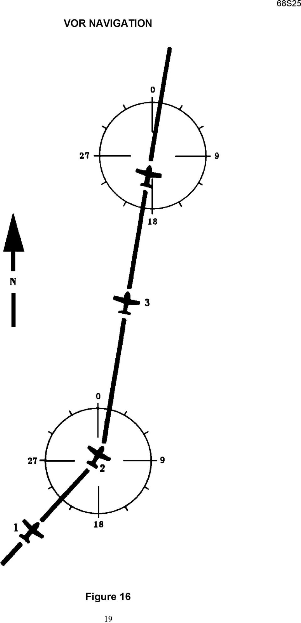
20 VOR NAVIGATION (See Fig. 16) 1. TO INTERCEPT A. Using Bearing Selector, dial desired course, inbound or outbound. B. Set identical heading on Course Selector D.G. C. After aircraft has stabilized, position coupler mode selector knob to OMNI mode. NOTE: If less than 45 from selected radial, aircraft will intercept before station. If more than 45, interception will occur after station passage. D. As aircraft nears selected radial, interception and crosswind will be automatically accomplished without further switching. E. As the aircraft nears the OMNI station, (½ mile) the zone of confusion will direct an S turn in alternate directions as the OMNI indicator needle swings. This alternate banking, limited to the standard D.G. bank angle, is an indication of station passage. 2. TO SELECT NEW COURSE A. To select any different outbound course or radial, including reciprocal of the previous inbound radial, dial the new course into the Course Selector D.G. B. Rotate OBS to the new course. C. Aircraft will automatically turn, in the shortest direction to the interception heading for the new course. 3. TO CHANGE STATIONS A. If same course is desired, merely tune receiver to new station frequency. B. If different course is desired, position coupler mode selector to HDG Mode. C. Dial Course Selector D.G. to new course. D. Dial OBS to new course. E. Position mode selector to OMNI mode. 20
 the zone of confusion will direct an S turn in alternate directions as the OMNI indicator needle swings.")
21 VOR APPROACH Figure 17 21
22 VOR APPROACH (See Fig.17) 1. Track inbound to station as described in VOR Navigation section. 2. After station passage (when S turn starts) dial outbound course on Course Selector in D.G. then dial same course on OBS. 3. After established on outbound radial, position mode selector to HDG mode and select outbound procedure turn heading. 4. After one minute, dial inbound procedure turn heading on Course Selector D.G. dialing toward desired turn. Set OBS to inbound course. 5. When 90 to inbound course, dial Course Selector D.G. to inbound course and position mode selector to OMNI mode. 6. If holding pattern is desired, position mode selector on HDG mode at station passage inbound and select outbound heading in direction of turn. 7. After elapsed time, dial inbound course on Course Selector D.G. 8. When 90 to radial, position mode selector on OMNI mode. NOTE NOTE: For precise tracking over Omni Station, without S turn, position mode selector on HDG. Until station passage. 22
23 ILS APPROACH NORMAL 23
24 Figure 18 24
25 ILS APPROACH--NORMAL (See Fig. 18) 1. To Intercept A. Dial ILS outbound on Course Selector D.G. B. When stabilized; position mode selector to LOC REV mode. 2. After interception and when beyond outer marker, position mode selector to HDG and dial outbound procedure turn heading. 3. After one minute, dial inbound procedure turn heading in direction of turn. 4. When between 90 and 45 to ILS inbound course, dial inbound course on Course Selector D.G. and position mode selector to LOC NORM mode. 5. When beyond midpoint of runway, or when missed approach is elected, position mode selector to HDG mode and execute missed approach procedure. 25
26 ILS APPROACH--BACK COURSE FIG
27 ILS APPROACH--BACK COURSE (See Fig. 19) 1. To Intercept A. Dial ILS Back Course outbound heading on Course Selector D.G. B. When stabilized, position mode selector to LOC NORM mode. 2. After interception and when beyond fix, position mode selector to HDG and dial outbound procedure turn heading. 3. After one minute, dial inbound procedure turn heading indirection of turn. 4. When between 90 and 45 to inbound course, dial inbound course on Course Selector D.G. and position mode selector on LOC REV mode. 5. Approximately ½ mile away from runway, position mode selector to HDG mode to prevent S turn over ILS station near runway threshold. 27
28 INTERCEPT CHARACTERISTICS Figure 20 (1) BEYOND 2 MILES FROM STATION: Aircraft approaches course at approximately 45 intercept angle until omni needle deflection is 50% of full scale, then turns to required heading (cross wind corrected for) with no overshoot of course. Figure 21 (2) CLOSE IN INTERCEPT: With a given intercept angle established the time required to pass through the active region near the desired radial (-50% full needle deflection) is proportional to the distance from the station. For this reason overshoot occurs when close in intercepts are made. (This is true of all systems, since the turning rate or bank angle must be limited). the three paths show what might be expected as the intercept distance is made nearer and then finally at the station. It will be noted that if the intercept heading takes the aircraft very near to the station, no maneuvering would occur until the aircraft has passed the station. 28
29 (3) INTERCEPT BEYOND THE STATION: Behavior beyond the station is similar to that explained in paragraph 2 in that as the intercept distance is made larger the tendency for overshoot is reduced. Figure 22 (4) CROSS WIND EFFECTS: Crosswind effects which might be expected are illustrated in the three plots below. curve A is the no wind condition and performance will be as per sections (1) thru (3). Curve B shows the effect of approaching the desired course. Because this rate is reduced by the wind, the tendency to overshoot is likewise reduced. Curve C shows the effect of a wind which tends to increase the rate at which the aircraft approaches the course. As would be expected, this will tend to cause an overshot. Figure 23 29
30 SYSTEM DESCRIPTION LOCALIZER AND/OR GLIDESLOPE COUPLER OPERATING INSTRUCTIONS The Century Flight Systems, Inc. Glideslope Coupler is a completely automatic analog computer that directs the Autopilot to intercept and track the approach glide path. The system automatically provides for variances in glide path angle, wind direction and various approach configurations of the aircraft. A self contained Logic Circuit provides for certain necessary conditions to be prevalent before automatic Glideslope coupling will occur. These conditions are explained in the following sections. Figure 24 LOCALIZER (Normal) MODE The Radio Coupler Mode Selector must be in the LOC NORM mode for at least 20 seconds before the Logic Circuit of the Glideslope Coupler is armed. This provides safety against inadvertent coupling when flying reverse course or tracking outbound on the front course. After coupling, the Glideslope may be de-coupled by the momentary switching of the mode selector from LOC- NORM position. NOTE: In order to use Localizer as a navigation aid where glideslope coupling is not desired, do not use the LOC NORM mode. The Lateral Guidance System will fly the Localizer beam in the OMNI mode once your position on the beam is established. ALTITUDE MODE The Altitude switch must also be depressed in the ALT position at least 20 seconds before the logic circuit of the Glideslope Coupler is armed. This condition provides for Glideslope Coupling from all normal procedures but prevents attempting coupling from a high rate descent. After coupling, the Glideslope may be de-coupled by momentarily switching OFF the ALT button. FIG 25 30
31 GLIDESLOPE DEVIATION INDICATOR The Glideslope Deviation Indicator must be deflected upward for at least 20 seconds before the logic circuit of the Glideslope Coupler is armed. This provides assurance that the Glide path will be intercepted from below in the normal manner and prevents inadvertent coupling from above. A 60% full scale deflection for 20 seconds will always accomplish arming. NOTE: Once coupled, the deviations Indicator will not de-couple the Glide regardless of needle deflection. The Deviation Indicator however must be monitored during approach to determine the aircraft s true position relative to the localizer beam and the glide path. INDICATOR LIGHT The Glideslope Coupler incorporates a panel mounted green indicator light. This light will turn ON at the same time automatic switching takes place to couple the Autopilot to the glide path. This light will stay lit until such time as the unit is decoupled. As this light only shows that the Glideslope Coupler is switched into the Autopilot and not actual position relative to glide path. The deviation indicator must be monitored during the approach. 31
32 ILS APPROACH PROCEDURES GLIDESLOPE APPROACH (Typical) 1. To intercept ILS a) Dial ILS outbound course on course selector D.G. b) Position Radio Coupler mode switch to LOC REV mode. c) Altitude Hold or Pitch Mode, for Altitude Control. 2. After intercept and at appropriate time, descent to approach altitude. 3. Press ALT Hold switch on console at published approach altitude. Dial procedure turn outbound heading on D.G. and position mode selector to HDG. 4. After one minute, dial the published in bound procedure turn heading moving D.G. course selector in direction of turn. When between 90 and 45 degrees to the inbound heading, dial inbound course on Course Selector D.G. and position mode selector to LOC NORM mode. NOTE: For optimum results, switch to localizer normal at 45. At this point the airplane will automatically intercept and track the localizer beam, you should be at the proper altitude and on ALT Hold and the glideslope deviation needle should be up. If the above conditions are met for 20 seconds or more, the Glideslope Coupler logic circuit will be armed. Adjust power for the gear down or normal approach speed. 5. Upon interception of glide path (when deviation needle drops to center) the Glideslope Coupler will automatically engage the indicator light will come on, and the aircraft will assure a preset nose-down attitude for descent. Drop gear and readjust power as necessary to maintain approach speed. Position flaps not to exceed 15 for approach at this time. Do not change gear or flap setting after initial glideslope intercept for remainder of glideslope coupler operation. Power and airspeed changes must be made carefully to prevent excessive attitude changes. NOTE: Monitor deviation indicators for actual position on Localizer and glide path. Transmissions may cause deviation needle to fluctuate on some radio installations. On such installations, the coupler will attempt to follow these deviations. A) Upon completion of Glideslope Coupler approach, or when VFR, disconnect Autopilot and adjust aircraft for landing configuration. B) For missed approach procedure, set Pitch Command to Climb Attitude. Switch Coupler to HDG mode and apply climb power, gear and flap up, disengage Altitude Hold and set Autopilot to missed approach HDG. 6. To de-couple any one of the following methods may be used: A) Switch ALT Hold OFF. this will de-couple Glideslope and revert pitch control to the Pitch Command Knob, which may be preset to desired climb attitude. B) Switch ALT Hold OFF. then ON. this will de-couple Glideslope and return to altitude hold. C) Switch Radio Coupler OFF, LOC-Norm mode. this will de-couple Glideslope and return pitch control to ALT Hold. D) Disconnect entire autopilot and hand fly aircraft. 32
33 CAUTION: Do not fly airplane on Autopilot below height above ground specified on placard (or flight manual supplement) for ALT loss, approach configuration, with 1 second delay recovery. Emergency Operation 1. In the event of a malfunction in the ROLL or PITCH SECTION, push the ROLL ON/OFF button OFF. This disengages both ROLL and PITCH SECTIONS of the Century III from the control system. 2. The PITCH TRIM SECTION may be overpowered manually. In the event of a malfunction in the PITCH-TRIM SECTION, pull the Pitch Trim circuit breaker. 3. The Century III ROLL SECTION may be overpowered manually on either control wheel. The Century III PITCH SECTION may be overpowered manually on either control wheel. 4. Engine Failure (Multi-Engine Airplanes) a) When on ROLL and PITCH mode only, any one of the following applies during engine failure. 1. Disengage Autopilot and trim aircraft. 2. Level wings with roll knob, and handle emergency. 3. Switch to HDG mode, (Course Selected) see (b). b) Autopilot on HDG or coupled: Autopilot will compensate for yaw caused by engine power loss by banking toward the operating engine. Perform normal Engine Out Emergency Procedures and re-trim aircraft. CAUTION When electrical power is first applied to the NSD-360A instrument, the compass card mat rotate or slew rapidly. This is NOT and indication that the compass system is orienting itself to the proper magnetic heading. The proper heading orientation must be verified and set prior to takeoff and should be verified prior to approach to landing using the magnetic compass. 33
34 Effective: July 4, 1975 LIMITED WARRANTY CENTURY FLIGHT SYSTEMS, INC. AUTOPILOT Each new Century Flight Systems, Inc. Autopilot is warranted by the manufacturer to be free from defects I material and workmanship under normal use, subject to the following conditions: 1. Century Flight Systems, Inc. will through its designated service facilities at its option either repair or replace new components which shall within (12 months after date of installation, be found to Century Flight Systems, Inc. satisfaction, to have been defective in material or workmanship under normal use. 2. The warranty registration must be signed and returned to Century Flight Systems, Inc. within ten days of equipment installation date. In the event that the registration card is not returned within this time, the date of shipment from the factory will be deemed to be the installation date. 3. This warranty will not apply to any product which has been installed, repaired, or altered in any way whatsoever in Century Flight Systems, Inc. opinion to adversely affect its performance or reliability, or which has bee subject to mis-use, contamination, negligence, or accident. 4. Cost of transportation, removal, or reinstallation are at the option of Century Flight Systems, Inc. 5. This is Century Flight Systems, Inc. sole express warranty with respect to the goods supplied herein. CENTURY FLIGHT SYSTEMS, INC. MAKES NO OTHER EXPRESS WARRANTY OF ANY KIND WHATSOEVER. CENTURY FLIGHT SYSTEMS, INC. EMPLOYEES MAY HAVE MADE ORAL STATEMENTS ABOUT THE PRODUCTS DESCRIBED IN THIS CONTRACT. SUCH STATEMENTS DO NOT CONSTITUTE WARRANTIES, SHALL NOT BE RELIED UPON BY THE CUSTOMER, AND ARE NOT PART OF THE SALE CONTRACT. 6. THE DURATION OF ANY IMPLIED WARRANTY, AND OF ALL WARRANTIES OF MERCHANTABILITY AND FITNESS FOR A PARTICULAR PURPOSE, SHALL BE LIMITED TO (12) MONTHS COMMENCING AT DATE OF INSTALLATION TO THE FULL EXTENT PERMITTED BY APPLICABLE LAW, CONSEQUENTIAL DAMAGE OR BREECH OF ANY WARRANTY ARE HEREBY DISCLAIMED AND EXCLUDED BY CENTURY FLIGHT SYSTEMS, INC. Century Flight Systems, Inc. P.O. Box 610 Municipal Airport Mineral Wells, Texas August
35 NOTES 35
36 NOTES 36
S-Tec System Thirty Autopilot
 Cirrus Design Section 9 Pilot s Operating Handbook and FAA Approved Airplane Flight Manual Supplement for S-Tec System Thirty Autopilot When the S-Tec System Thirty Autopilot is installed in the Cirrus
Revision Number Revision Date Insertion Date/Initials 1 st Ed. Feb 01, 00 2 nd Ed. Jun 24, 02 3rd Ed. Feb 15, 07
 List of Effective Pages * Asterisk indicates pages changed, added, or deleted by current revision. Retain this record in front of handbook. Upon receipt of a Record of Revisions revision, insert changes
For Information Only-Not approved for cockpit use.
 For Information Only-Not approved for cockpit use. List of Effective Pages *The asterisk indicates pages changed, added, or deleted by current change. Record of Revisions REVISION REVISION NUMBER DATE
Revision Number Revision Date Insertion Date/Initials 1 st Edition February 1992 2 nd Edition March 05, 2002
 GPS List of Effective Pages * Asterisk indicates pages changed, added, or deleted by revision. Record of Revisions Retain this record in front of handbook. Upon receipt of a revision, insert changes and
Global Positioning System Steering (GPSS) Converter Pilot s Operating Handbook
 Converter Pilot s Operating Handbook") Global Positioning System Steering (GPSS) Converter Pilot s Operating Handbook List of Effective Pages * Asterisk indicates pages changed, added, or deleted by revision. Retain this record in front of
Global Positioning System Steering (GPSS) Converter Pilot s Operating Handbook List of Effective Pages * Asterisk indicates pages changed, added, or deleted by revision. Retain this record in front of
S TEC. List of Effective Pages. Record of Revisions
 List of Effective Pages * Asterisk indicates pages changed, added, or deleted by current revision. Retain this record in front of handbook. Upon receipt of a Record of Revisions revision, insert changes
FLIGHT TRAINING (AEROPLANE) BASED ON JAR FCL - PPL(A) FLIGHT INSTRUCTION Syllabus
 BASED ON JAR FCL - PPL(A) FLIGHT INSTRUCTION Syllabus") FLIGHT TRAINING (AEROPLANE) BASED ON JAR FCL - PPL(A) FLIGHT INSTRUCTION Syllabus for MARSPOLAR, DUBAI UAE Exercise 1 Familiarisation with the aeroplane characteristics of the aeroplane cockpit layout
FLIGHT TRAINING (AEROPLANE) BASED ON JAR FCL - PPL(A) FLIGHT INSTRUCTION Syllabus for MARSPOLAR, DUBAI UAE Exercise 1 Familiarisation with the aeroplane characteristics of the aeroplane cockpit layout
KX 155A and KX 165A VHF Communication/Navigation Transceivers
 KX 155A and KX 165A VHF Communication/Navigation Transceivers KX 155A and KX 165A Operation (25 khz Versions) KX 155A/165A All controls required to operate the KX 155A and KX 165A are located on the unit
B777. Automatic Flight DO NOT USE FOR FLIGHT
 B777 Automatic Flight DO NOT USE FOR FLIGHT 4.10 Automatic Flight-Controls and Indicators Mode Control Panel (MCP) A/T ARM L R IAS MACH HDG TRK V/S FPA ALTITUDE A/P F/D ON OFF CLB CON IAS LNAV VNAV AUTO
2014 NIFA CRM Contestant Briefing Guide San Diego, California
 2014 NIFA CRM Contestant Briefing Guide San Diego, California Region 2 SAFECON 2014 November 12 15 This document supports the 2014 NIFA Collegiate Cockpit Resource Management Simulation and is not for
09 FLIGHT MANAGEMENT, NAVIGATION
 Course overview N E X T G E N E R A T I O N Airplane General Air Systems Warning Systems, Communications, Ice & Rain Protection Electrical Engines, APU, Fuel System Hydraulics, Flight Controls, Landing
G1000 Search Patterns. National Emergency Services Academy Mission Aircrew School (June 2013 Rev D)
") G1000 Search Patterns National Emergency Services Academy Mission Aircrew School (June 2013 Rev D) Standardized Visual Search Pattern method Visual search pattern techniques include: Minimum # of user
G1000 Search Patterns National Emergency Services Academy Mission Aircrew School (June 2013 Rev D) Standardized Visual Search Pattern method Visual search pattern techniques include: Minimum # of user
This section includes performance data on the King Air B200. Information consists of:
 King Air B200 POH Pilot's Operating Handbook: This section includes performance data on the King Air B200. Information consists of: 1. Critical Airspeeds 2. Operating NOTAMS 3. Fuel Loading Formula Checklists:
DIRECCION DE PERSONAL AERONAUTICO DPTO. DE INSTRUCCION PREGUNTAS Y OPCIONES POR TEMA
 MT DIREION DE PERSONL ERONUTIO DPTO. DE INSTRUION PREGUNTS Y OPIONES POR TEM Pag.: 1 TEM: 0321 INSTRUTOR_DVNED_06_ENR FLT & NVIGTION OD_PREG: PREGUNT: RPT: 6856 GIVEN: Departure path... straight out Takeoff
For Microsoft Flight Simulator X 2008 FriendlyPanels. All right reserved
 FriendlyPanels Software For Microsoft Flight Simulator X 2008 FriendlyPanels. All right reserved REPLACEMENT NAVIGATION GAUGES FOR FSX AIRCRAFT 1 1. Introduction. 2. Requirements 3. Installing the pack
The KFC 225 s Internal GPSS. by Dan Herr, TTCF Member. November 2014
 The KFC 225 s Internal GPSS by Dan Herr, TTCF Member November 2014 The KFC 225 was designed after the advent of aviation GPS, but before WAAS and before GPS approaches had a glideslope. Unlike VOR navigation,
FLIGHT CONTROLS 1. GENERAL 2. MAIN COMPONENTS AND SUBSYSTEMS ROLL CONTROL. Smartcockpit.com BOEING 737 SYSTEMS REVIEW Page 1
 Smartcockpit.com BOEING 737 SYSTEMS REVIEW Page 1 FLIGHT CONTROLS 1. GENERAL The primary flight controls, ailerons, elevators and rudders, are hydraulically powered. Hydraulic power is provided from hydraulic
Introduction to the iefis Explorer
 Introduction to the iefis Explorer A brief primer to the new iefis Explorer from MGL Avionics The Explorer EFIS introduces a custom developed touch pressure sensitive LCD screen aimed exclusively at the
Oral Preparation Questions
 Oral Preparation Questions The oral section of the practical test is the time when you need to demonstrate your understanding of the various tasks listed in the practical test standards and the factors
Automation at Odds. A 737 stalled when a radio altimeter malfunction caused the autothrottle and autopilot to diverge during an approach to Schiphol.
 Automation at Odds The pilots of a Boeing 737-800 did not heed indications of a significant decrease in airspeed until the stick shaker activated on final approach to Runway 18R at Amsterdam (Netherlands)
ENGINE FIRE / SEVERE DAMAGE / SEPARATION ON TAKEOFF
 ENGINE FIRE / SEVERE DAMAGE / SEPARATION ON TAKEOFF According to RYANAIR Procedures PF PM REMARKS Control the aircraft (FULL T/O thrust can be manually selected) Announce «ENGINE FAILURE» or «ENGINE FIRE»
Information regarding the Lockheed F-104 Starfighter F-104 LN-3. An article published in the Zipper Magazine #48. December-2001. Theo N.M.M.
 Information regarding the Lockheed F-104 Starfighter F-104 LN-3 An article published in the Zipper Magazine #48 December-2001 Author: Country: Website: Email: Theo N.M.M. Stoelinga The Netherlands http://www.xs4all.nl/~chair
Low Level Windshear Alert System (LLWAS) An integral part of the U.S. FAA Wind-shear safety program
 An integral part of the U.S. FAA Wind-shear safety program") Low Level Windshear Alert System (LLWAS) An integral part of the U.S. FAA Wind-shear safety program Low-level windshear is a hazard to aircraft in the airport runway corridors. With Climatronics LLWAS,
Low Level Windshear Alert System (LLWAS) An integral part of the U.S. FAA Wind-shear safety program Low-level windshear is a hazard to aircraft in the airport runway corridors. With Climatronics LLWAS,
12 AERO Second-Quarter 2003 April CAPT. RAY CRAIG 737 CHIEF PILOT FLIGHT OPERATIONS BOEING COMMERCIAL AIRPLANES
 CAPT. RAY CRAIG 737 CHIEF PILOT FLIGHT OPERATIONS BOEING COMMERCIAL AIRPLANES DREW HOUCK ASSOCIATE TECHNICAL FELLOW FLIGHT DECK DISPLAYS BOEING COMMERCIAL AIRPLANES ROLAN SHOMBER ASSOCIATE TECHNICAL FELLOW
B777. Landing Gear DO NOT USE FOR FLIGHT
 B777 Landing Gear DO NOT USE FOR FLIGHT Introduction The airplane has two main landing gear and a single nose gear. The nose gear is a conventional steerable two wheel unit. Each main gear has six wheels
MK12D TSO (MK12, MK12A, MK12B REPLACEMENT RADIO)
") NARCO AVIONICS MK12D TSO (MK12, MK12A, MK12B REPLACEMENT RADIO) ADDENDUM INSTALLATION MANUAL 03118-0620R NARCO AVIONICS INC. 270 COMMERCE DRIVE FT. WASHINGTON, PA. 19034 U.S.A. PRINTED IN U.S.A. JUNE,
NARCO AVIONICS MK12D TSO (MK12, MK12A, MK12B REPLACEMENT RADIO) ADDENDUM INSTALLATION MANUAL 03118-0620R NARCO AVIONICS INC. 270 COMMERCE DRIVE FT. WASHINGTON, PA. 19034 U.S.A. PRINTED IN U.S.A. JUNE,
High Alpha 3D Maneuvers
 High Alpha 3D Maneuvers Harrier Pass Elevator Back Flip Parachute Whip Stalls Rolling Harrier 3D Rolling Turn 3D Knife Edge C-82 Rudder Warmup Note: Every flight mode and maneuver presented in this section
Aviation Safety Prize ecfi Tasks
 2008 NASA "The PAV Challenge" Aviation Safety Prize ecfi Tasks The Aviation Safety Prize (ASP) will be based upon a set of defined tasks that can be flight demonstrated to the CAFE Test Pilots by each
Multi Engine Oral Exam Questions
 Multi Engine Oral Exam Questions 1. What are the requirements for a multi-engine rating? 2. What is the max rated horse power at sea level? At 12,000 msl? 3. What is the rated engine speed? 4. What is
harbor cub Electric Remote Control Airplane Model 92906 assembly & Operating Instructions
 harbor cub Electric Remote Control Airplane Model 92906 assembly & Operating Instructions IMPORTANT: If damage is caused due to a crash, your warranty is void. Visit our website at: http://www.harborfreight.com
Light Sport West Standard Flight Training Procedures for N110GX (Remos GX, 100 H.P.)
") Light Sport West Standard Flight Training Procedures for N110GX (Remos GX, 100 H.P.) Welcome to Light Sport West! Thank you for giving us the opportunity to provide all of your flight training needs. Our
Light Sport West Standard Flight Training Procedures for N110GX (Remos GX, 100 H.P.) Welcome to Light Sport West! Thank you for giving us the opportunity to provide all of your flight training needs. Our
CYCLOPS OSD USER MANUAL 5.0
 CYCLOPS OSD USER MANUAL 5.0 Thank you for choosing CYCLOPS OSD V5.0 New features: CYCLOPS OSD V5.0 is incorporated with Autopilot function and infrared attitude sensor capable of controlling aircraft's
Automated Flight Control
 Chapter 4 Automated Flight Control Introduction This chapter introduces automated flight control in the advanced avionics cockpit. You will learn to use an autopilot system that can significantly reduce
CIRRUS AIRPLANE MAINTENANCE MANUAL
 UNSCHEDULED MAINTENANCE CHECKS 1. DESCRIPTION The following describes those maintenance checks and inspections on the aircraft which are dictated by special or unusual conditions which are not related
Multi-Engine Training And The PTS
 Multi-Engine Training And The PTS GHAFI John Sollinger/Larry Hendrickson October 28, 2000 Overview FAR differences between original and add-on Multi-Engine PTS Training methods Common training scenarios
Instruction Manual Bedienungsanleitung Manuel d utilisation Manuale di Istruzioni
 Instruction Manual Bedienungsanleitung Manuel d utilisation Manuale di Istruzioni EN Getting Started To get more information, including details on downloading the Spektrum AS3X Mobile Programming Application,
AutoGlow Installation and User s Manual. Installation and User s Manual. OSA AutoGlow. Figure 1. AutoGlow Introduction
 AutoGlow TM Installation and User s Manual Automatic Mode Velocity Sensing EEPROM OSA AutoGlow Thank you for purchasing the AutoGlow automatic glow plug control system. AutoGlow allows the model aviation
Cessna 172SP & NAV III Maneuvers Checklist
 Cessna 172SP & NAV III Maneuvers Checklist Introduction Power Settings This document is intended to introduce to you the standard method of performing maneuvers in Sunair Aviation s Cessna 172SP and NAV
GENERATOR START CONTROL MODULE - MINI (2 Wire to 3 Wire)
") FEATURES & APPLICATIONS Inexpensive 2 wire to 3 wire start controller for electric start high speed gas generators. Optimized for use with Outback Invertors. Supports three types of 3 wire generator control
FEATURES & APPLICATIONS Inexpensive 2 wire to 3 wire start controller for electric start high speed gas generators. Optimized for use with Outback Invertors. Supports three types of 3 wire generator control
OPERATIONS CIRCULAR. OC NO 2 OF 2014 Date: 1 st May 2014. Continuous Descent Final Approach (CDFA) 1. PURPOSE
 1. PURPOSE") GOVERNMENT OF INDIA CIVIL AVIATION DEPARTMENT DIRECTOR GENERAL OF CIVIL AVIATION OC NO 2 OF 2014 Date: 1 st May 2014 OPERATIONS CIRCULAR Subject: Continuous Descent Final Approach (CDFA) 1. PURPOSE This
GOVERNMENT OF INDIA CIVIL AVIATION DEPARTMENT DIRECTOR GENERAL OF CIVIL AVIATION OC NO 2 OF 2014 Date: 1 st May 2014 OPERATIONS CIRCULAR Subject: Continuous Descent Final Approach (CDFA) 1. PURPOSE This
APPENDIX 3-B Airplane Upset Recovery Briefing. Briefing. Figure 3-B.1
 APPENDIX 3-B Airplane Upset Recovery Briefing Industry Solutions for Large Swept-Wing Turbofan Airplanes Typically Seating More Than 100 Passengers Briefing Figure 3-B.1 Revision 1_August 2004 Airplane
Part I - Installation
 400 Series Pressure and Differential Pressure Switches Types: H400, H402, H403, H400K, H402K, J400, J402, J403, J400K, J402K UNITED ELECTRIC CONTROLS Installation and Maintenance Instructions Please read
Compiled by Matt Zagoren
 The information provided in this document is to be used during simulated flight only and is not intended to be used in real life. Attention VA's - you may post this file on your site for download. Please
AIRCRAFT GENERAL www.theaviatornetwork.com GTM 1.1 2005 1-30-05 CONTENTS
 www.theaviatornetwork.com GTM 1.1 CONTENTS INTRODUCTION... 1.2 GENERAL AIRPLANE... 1.2 Fuselage... 1.2 Wing... 1.2 Tail... 1.2 PROPELLER TIP CLEARANCE... 1.2 LANDING GEAR STRUT EXTENSION (NORMAL)... 1.2
SPORT PILOT TRAINING SYLLABUS
 Checked out from the Members Only Library Page 1 of 13 Society of Aviation and Flight Educators www.safepilots.0rg SPORT PILOT TRAINING SYLLABUS LESSON ONE: INTRODUCTORY FLIGHT TIME: 1 hour Ground Instruction;
USB/VGA Cat 5 UTP Console Extender
 USB/VGA Cat 5 UTP Console Extender SV565UTPU SV565UTPUGB SV565UTPUEU Instruction Manual FCC Compliance Statement This equipment has been tested and found to comply with the limits for a Class B digital
Cessna 172S. Flight Training Standardization Guide REVISION: ORIGINAL
 Cessna 172S Flight Training Standardization Guide REVISION: ORIGINAL Contents Purpose... 4 Normal and Crosswind Takeoff and Climb... 5 Normal and Crosswind Landing... 6 Soft Field Takeoff and Climb...
AIRCRAFT PERFORMANCE Pressure Altitude And Density Altitude
 Performance- Page 67 AIRCRAFT PERFORMANCE Pressure Altitude And Density Altitude Pressure altitude is indicated altitude corrected for nonstandard pressure. It is determined by setting 29.92 in the altimeter
The purposes of this experiment are to test Faraday's Law qualitatively and to test Lenz's Law.
 260 17-1 I. THEORY EXPERIMENT 17 QUALITATIVE STUDY OF INDUCED EMF Along the extended central axis of a bar magnet, the magnetic field vector B r, on the side nearer the North pole, points away from this
Nomad WINGS FLAP OPERATING LIMITATIONS
 WINGS FLAP OPERATING LIMITATIONS 1. PLANNING INFORMATION A. Effectivity (1) Aircraft affected: N22 Series line sequence numbers 1 to 9, 11 to 29, 31, 33, 35, 37, 39 to 41, 43, 45, 47 to 59, 63, 65 to 70,
Guardian 2D/3D Stabilizer. Document Version 2.0 Assembled in Taiwan
 Guardian 2D/3D Stabilizer Document Version 2.0 Assembled in Taiwan Introduction Thank you for your purchase! Based on Eagle Tree's proven inertial stabilization technology, the Guardian 2D/3D Stabilizer
This is the fourth of a series of Atlantic Sun Airways CAT B pilot procedures and checklists for our fleet. Use them with good judgment.
 This is the fourth of a series of Atlantic Sun Airways CAT B pilot procedures and checklists for our fleet. Use them with good judgment. Dimensions: Wing Span: 112 ft 7 in Length: 129 ft 6 in Height: 41
VARIABLE STABILITY FLIGHT OPERATIONS MANUAL
 SPACE INSTITUTE VARIABLE STABILITY FLIGHT OPERATIONS MANUAL Prepared by the Aviation Systems and Flight Research Department September 2004 Index 1.1 General Description...1 1.2 Variable Stability System...5
TOYOTA TECHNICAL. An example of a tire pressure monitor valve sub-assembly. This mounts to a drop area in the wheel.
 TOYOTA TIRE PRESSURE WARNING SYSTEM Toyota uses various tire pressure warning systems. Here, we ll discuss the system featured on the 2006 Land Cruiser. Combination meter warning reset switch warning reset
Aviation Supplies & Academics, Inc. 7005 132nd Place SE Newcastle, Washington 98059-3153 www.asa2fly.com
 The Pilot s Manual 1: Flight School Aviation Supplies & Academics, Inc. 7005 132nd Place SE Newcastle, Washington 98059-3153 www.asa2fly.com Originally published by Aviation Theory Centre 1990 1993. Fourth
SELF-STEERING AXLE TABLE OF CONTENTS
 SELF-STEERING AXLE TABLE OF CONTENTS Section 1 - Introduction Section 2 - Pre-Installation Check List Section 3 - Ride Height Adjustments Section 4 - Suspension Mount Section 5 - Axle Mount Section 6 -
General Characteristics
 This is the third of a series of Atlantic Sun Airways CAT C pilot procedures and checklists for our fleet. Use them with good judgment. Note, the start procedures may vary from FS9 Panel to Panel. However
Electric Landing Gear controllers and sequencer LGC12 / LGC 13C
 Electric Landing Gear controllers and sequencer LGC12 / LGC 13C Users Guide. Torrent d en Puig, 31. 08358, Arenys de Munt, Barcelona,Catalonia,Spain E-mail: [email protected]. Fax: +34 933 969 743 web: www.xicoy.com
Airglas, Inc. MANUAL NO. GLH3000-105-AHSA. MODEL GLH3000 Ski Kit Actuated by Wipaire, Inc. Amphibious Float Hydraulic System
 Airglas, Inc. Amphibious hydraulic system addendum to Instructions for Continued Airworthiness Including Installation, Maintenance and Service Instructions MANUAL NO. GLH3000-105-AHSA MODEL GLH3000 Ski
AUTOMATIC SWINGING DOOR
 AAADM American Association of Automatic Door Manufacturers AUTOMATIC SWINGING DOOR OWNER'S MANUAL Distributed by: Section Contents Page Caution 2 To Our Customers 3 Service Availability 3 Compliance with
PixController, Inc. Wireless Digital PIR Sensor
 PixController, Inc. Wireless Digital PIR Sensor Model: SEN-400 User s Manual Version 1.00 WARRANTY REGISTRATION PixController, Inc. warrants products sold by it and guarantees to correct, by repair or
LOG OF REVISIONS Revision Page FAA Date of Number Number(s) Description Approved Approval A All Initial Release K.
 Description Approved Approval A All Initial Release K.") LOG OF REVISIONS Revision Page FAA Date of Number Number(s) Description Approved Approval A All Initial Release K. Campbell* 4/4/00 B 5, 10 Remove SKYWATCH and add GTX 330 TIS G. Baker* 11/21/02 C All
LOG OF REVISIONS Revision Page FAA Date of Number Number(s) Description Approved Approval A All Initial Release K. Campbell* 4/4/00 B 5, 10 Remove SKYWATCH and add GTX 330 TIS G. Baker* 11/21/02 C All
INSTRUCTIONS FOR MAGNUM DS TRIP UNIT TESTING USING TEST KIT SYLES 140D481G02R, 140D481G02RR, 140D481G03 AND 140D481G04
 I.L. 32-693 A INSTRUCTIONS FOR MAGNUM DS TRIP UNIT TESTING USING TEST KIT SYLES 140D481G02R, 140D481G02RR, 140D481G03 AND 140D481G04 DANGER DO NOT ATTEMPT TO INSTALL OR PERFORM MAINTE- NANCE ON EQUIPMENT
1 For All Non-Programmable Digital Thermostat
 OWNER'S MANUAL P/N P474-0100 1 For All Non-Programmable Digital Thermostat TOTALINE 68 Dual Setpoint Very easy to program Thermoglow Backlight No batteries required Auto-Changeover Locking Keypad Meets
Instrument Pilot Rating Course (ASEL) Training Syllabus FAR Part 61
 Training Syllabus FAR Part 61") Instrument Pilot Rating Course (ASEL) Training Syllabus FAR Part 61 Property of Tech Aviation Flight School. Reproduction of this manual in full or part is strictly prohibited by law. Distribution or use
Instrument Pilot Rating Course (ASEL) Training Syllabus FAR Part 61 Property of Tech Aviation Flight School. Reproduction of this manual in full or part is strictly prohibited by law. Distribution or use
This is the third of a series of Atlantic Sun Airways CAT B pilot procedures and checklists for our fleet. Use them with good judgment.
 This is the third of a series of Atlantic Sun Airways CAT B pilot procedures and checklists for our fleet. Use them with good judgment. Dimensions: Span 107 ft 10 in Length 147 ft 10 in Height 29ft 7 in
Flightlab Ground School 5. Longitudinal Static Stability
 Flightlab Ground School 5. Longitudinal Static Stability Copyright Flight Emergency & Advanced Maneuvers Training, Inc. dba Flightlab, 2009. All rights reserved. For Training Purposes Only Longitudinal
P/N 135A-970-022 FAA Approved: 12/6/2007 Section 9 Initial Release Page 1 of 8
 FAA APPROVED AIRPLANE FLIGHT MANUAL SUPPLEMENT FOR GARMIN SL40 NAV/COMM Serial No: Registration No: When the GARMIN SL40 COM radio is installed in the Liberty Aerospace XL-2, this supplement is applicable
X-Plane Remote for the iphone, ipod Touch, and ipad Operation Manual. Table of Contents. II. The EFIS Moving Map Display. 5. Tech Support...
 1 X-Plane Remote for the iphone, ipod Touch, and ipad Operation Manual II. The EFIS Moving Map Display 5. Tech Support... 23 Table of Contents 1. Introduction to X-Plane Remote... 3 I. Differences Between
Lab 8 Notes Basic Aircraft Design Rules 6 Apr 06
 Lab 8 Notes Basic Aircraft Design Rules 6 Apr 06 Nomenclature x, y longitudinal, spanwise positions S reference area (wing area) b wing span c average wing chord ( = S/b ) AR wing aspect ratio C L lift
Garmin GNC 300XL Pilot s Quick Reference Guide ---------------------------------------------------------------
 Garmin GNC 300XL Pilot s Quick Reference Guide --------------------------------------------------------------- CURSOR/ DATA ENTRY Cursor control: The cursor key is used to activate the cursor in the comm
Global Avionics Training Specialists, LLC.
 Global Avionics Training Specialists, LLC. PRIMUS 2000/DORNIER 328 JET INTEGRATED AVIONICS SYSTEM LINE MAINTENANCE FAMILIARIZATION COURSE SYLLABUS I. INTRODUCTION A. SYSTEM DESCRIPTION The PRIMUS 2000
Adaptive cruise control (ACC)
") Adaptive cruise control (ACC) PRINCIPLE OF OPERATION The Adaptive Cruise Control (ACC) system is designed to assist the driver in maintaining a gap from the vehicle ahead, or maintaining a set road speed,
Adaptive cruise control (ACC) PRINCIPLE OF OPERATION The Adaptive Cruise Control (ACC) system is designed to assist the driver in maintaining a gap from the vehicle ahead, or maintaining a set road speed,
VFR Day Emergencies - C172R
 Pilot Level: References: Note: VFR Day Emergencies - C172R Student Pilot. FAA-H-8083-3A, Chapter 16, Federal Aviation Regulations, Cessna 172R PIM, Aeronautical Information Manual, King Schools (DVDs):
FAA-P-8740-52 AFS-820-2000
 S1 Introduction You fly in actual instrument weather conditions and make enough approaches to keep "current," take your flight review from a good instructor, know the "Normal" and "Emergency" procedure
The SeaRey - An Introduction
 The SeaRey - An Introduction Welcome to the beautiful Progressive Aerodyne SeaRey. The SeaRey is a very special aircraft. Created by a small team of engineers the SeaRey is perhaps the ultimate kit built
SL720 GYRO/PC INTERFACE MANUAL
 SL720 GYRO/PC INTERFACE MANUAL INTRODUCTION The SL720 gyro has a 'PC' port that allows the internal settings of the gyro to be examined and adjusted to users' requirements. For most users the pre-loaded
0 28 November 2011 N/A First Release of Manual 1 24 February 2012 Page 21 Error in FY31AP connection diagram corrected.
 Rev 1: 24 February 2012 FEIYU TECH FY31AP Autopilot System Installation & Operation Guide Guilin Feiyu Electronic Technology Co., Ltd Rm. B305, Innovation Building, Information Industry Park, Chaoyang
SCORPION. micron security products
 SCORPION 4120 6020 & 8020 USER INSTRUCTIONS Thank you for purchasing a Quality Micron Security Alarm Controller. Micron product is manufactured to exacting quality standards. We understand the importance
LiteAide OWNER'S MANUAL PREASSEMBLED AUTOMATIC SECURITY FLOODLIGHTS MOTION SENSOR SECURITY LIGHTING SYSTEMS
 OWNER'S MANUAL PREASSEMBLED AUTOMATIC SECURITY FLOODLIGHTS MOTION SENSOR SECURITY LIGHTING SYSTEMS LiteAide HE-100B HE-100BW HE-112 HE-112W HE-117 HE-117W HE-117-2B OWNER'S MANUAL FLOOD LAMPS (BULBS) Your
BOMBARDIER CRJ700. Bombardier CRJ700 Aircraft Reference
 Bombardier CRJ700 Aircraft Reference V 1 Takeoff Decision Speed, dry runway 50,000 lbs, (flaps 8) 144 KIAS 50,000 lbs, (flaps 20) 134 KIAS V R Rotation Speed, dry runway 50,000 lbs, (flaps 8) 144 KIAS
parts of an airplane Getting on an Airplane BOX Museum Aeronautics Research Mission Directorate in a Series
 National Aeronautics and Space Administration GRADES K-2 Aeronautics Research Mission Directorate Museum in a BOX Series www.nasa.gov parts of an airplane Getting on an Airplane MUSEUM IN A BOX Getting
Universal Wireless Effects Controller USER S GUIDE SA115
 Universal Wireless Effects Controller USER S GUIDE SA115 Welcome Thank you for purchasing this Hot Hand 3 Universal Wireless Effects Controller. We hope that the new functionality of the Hot Hand 3 unit
CHAPTER 6. Precision Approach Systems
 ELEC4504 Avionics Systems 77 CHAPTER 6. Precision Approach Systems 6.1. Introduction The word approach is used to describe the phase of flight which immediately precedes the landing. While the approach
INTERIM STATEMENT. Accident occurred to AW609 registration marks N609AG, on 30 th October 2015, in Tronzano Vercellese (VC), Italy.
, Italy.") INTERIM STATEMENT Accident occurred to AW609 registration marks N609AG, on 30 th October 2015, in Tronzano Vercellese (VC), Italy. 1. Foreword. On 30 th October 2015, the experimental tiltrotor AW609 registration
INTERIM STATEMENT Accident occurred to AW609 registration marks N609AG, on 30 th October 2015, in Tronzano Vercellese (VC), Italy. 1. Foreword. On 30 th October 2015, the experimental tiltrotor AW609 registration
Automatic Swinging Door Systems
 Automatic Swinging Door Systems Operation and Maintenance Manual Including: Magic-Force, Magic-Swing and Magic-Access Contents Section Page Caution Statement. 2 To Our Customers 3 Service Availability...
Basic Aviation Training Device
 FLYIT SIMULATORS, Inc. Basic Aviation Training Device Model PHS - 1 FLYIT Simulators Inc. 5931Sea Lion Pl #110 Carlsbad, CA 92010 USA Revised on 10/30/2014 Page 1 of 53 Device Description and Overview
DCX300 - DCX400 - DCX600
 Ph: 541-476-3565 Fax: 541-476-3566 DCX300 - DCX400 - DCX SEPARATELY EXCITED DC MOTOR CONROLLERS Alltrax motor controllers are designed to work with various golf cars from different manufacturers. Use the
Tipping Bucket Rain Gauge Models 6011-A 6011-B
 Tipping Bucket Rain Gauge Models 6011-A 6011-B User s Manual 1165 National Drive Sacramento, CA 95834 800.824.5873 Table of Contents General Information... 1 Introduction... 1 Installation General... 2
Takeoff Tools TM Crosswind Calculator Instructions Copyright 2005 by Eric C. King. All rights reserved. Rev. 11Sep05. How to Use
 Takeoff Tools TM Crosswind Calculator Instructions Copyright 2005 by Eric C. King. All rights reserved. Rev. 11Sep05 Takeoff Tools TM Suppose you re arriving at, or about to depart from, an airport. You
COMSPHERE 6700 SERIES NETWORK MANAGEMENT SYSTEM
 COMSPHERE 6700 SERIES NETWORK MANAGEMENT SYSTEM SECURITY MANAGER FEATURE SUPPLEMENT Document No. 6700-A2-GB41-30 February 1998 Copyright 1998 Paradyne Corporation. All rights reserved. Printed in U.S.A.
AIRCRAFT NOISE ABATEMENT OPERATING PROCEDURES AND RESTRICTIONS
 AIRCRAFT NOISE ABATEMENT OPERATING PROCEDURES AND RESTRICTIONS This section sets forth the Los Angeles World Airports (LAWA s) informal noise abatement traffic; flight and runway use procedures and includes
PS 155 WIRELESS INTERCOM USER MANUAL
 PS 155 INTERFACE TO SIMPLEX WIRELESS INTERCOM USER MANUAL Issue 2011 ASL Intercom BV DESIGNED AND MANUFACTURED BY: ASL INTERCOM BV ZONNEBAAN 42 3542 EG UTRECHT THE NETHERLANDS PHONE: +31 (0)30 2411901
Flight Operations Briefing Notes
 Flight Operations Briefing Notes I Introduction Encountering wake turbulence in flight can be a surprising experience, both for crews and passengers. Wake turbulence occurs suddenly, and is usually accompanied
Directed Passive Keyless Entry System (PKE) Model 2102T Owner s Guide
 Model 2102T Owner s Guide") Directed Passive Keyless Entry System (PKE) Model 2102T Owner s Guide 2012 Directed, Vista, CA G2102T Contents Government regulations...4 Warning! Safety first...6 Important information...6 System maintenance...6
Directed Passive Keyless Entry System (PKE) Model 2102T Owner s Guide 2012 Directed, Vista, CA G2102T Contents Government regulations...4 Warning! Safety first...6 Important information...6 System maintenance...6
LANDING GEAR & BRAKES www.theaviatornetwork.com GTM 14.1 2005 1-30-05 CONTENTS INTRODUCTION... 14.2
 www.theaviatornetwork.com GTM 14.1 CONTENTS INTRODUCTION... 14.2 GENERAL... 14.2 MAIN LANDING GEAR... 14.2 Landing Gear Latch Lever and Handle... 14.2 Landing Gear Pressure Gauge... 14.2 Landing Gear Warning
Mountain Air Country Club Pilot s Manual Version 1.07 Mountain Air Pilots Association
 Mountain Air Country Club Pilot s Manual Version 1.07 Mountain Air Pilots Association John M. Cuckler, Editor Educational Committee: John Ransom, Eddie Franco, Doug Pilkington, Clark Jernigan, Lionel Kuhn
Flight Safety Foundation. Approach-and-landing Accident Reduction. Tool Kit. FSF ALAR Briefing Note 4.2 Energy Management
 Flight Safety Foundation Approach-and-landing Accident Reduction Tool Kit FSF ALAR Briefing Note 4.2 Energy Management The flight crew s inability to assess or to manage the aircraft s energy condition
Assembly and Operating Manual Nano warbirds FW 190 Specification: *Length: 18 1/2"(470mm) *Wing Span: 21 7/10"(550mm)
 *Wing Span: 21 7/10(550mm)") Assembly and Operating Manual Nano warbirds FW 190 Specification: *Length: 18 1/2"(470mm) *Wing Span: 21 7/10"(550mm) *Flying Weight: 6 1/2 oz (185g) Dear customer, Congratulations on your choice of a
Assembly and Operating Manual Nano warbirds FW 190 Specification: *Length: 18 1/2"(470mm) *Wing Span: 21 7/10"(550mm) *Flying Weight: 6 1/2 oz (185g) Dear customer, Congratulations on your choice of a