User s Manual Laminar Flow Elements
|
|
|
- Dina Crawford
- 8 years ago
- Views:
Transcription

1 501: User s Manual Laminar Flow Elements Madison Avenue Cleveland, Ohio Tel: meriam@meriam.com Web: 1

2 TABLE OF CONTENTS Subject Page Introduction... 3 Inspection... 3 Installation... 3 Operation... 4 Typical Installations... 4 Calibration Curve/Table... 5 Actual Standard and Mass Flow Equations Reading your Laminar Flow Element Curve/Table... 9 Correction Factor Tables/Curves Air Humidity for Density... 8 Air Humidity for Viscosity... 8 Pressure Air Viscosity Air Temperature/Viscosity Temperature Maintenance Troubleshooting LFE Dimensions

3 Introduction Because of their inherently high accuracy, stable calibration, excellent response time and repeatability, Laminar Flow Elements (LFEs) excel in critical gas and air flow measurements and are frequently utilized in validating calibration standards. Standard models are available to measure as little as 0.2 SCCM (5.9 E-06 SCFM) to as much as 2250 SCFM at standard conditions. Custom models for up to 15,000 SCFM of air are available. Stainless steel or aluminum materials make LFEs compatible with most gases and flow rate of gas mixtures can also be measured when the percentages of component gases and mixture properties are known. Higher accuracies can be achieved when used in conjunction with the Meriam MDT500 multivariable transmitter and software package. The LFE matrix is made from individual SS tubes or windings of SS foil, these tubes are long enough, relative to their inside diameter to cause laminar flow to occur inside each tube, the result is a near linear relationship between DP and flow rate. The DP generated across the matrix responds very quickly to changes in flow and pressure loss to the system is reduced as each LFE is sized to produce no greater than 8 water column at maximum flowing conditions. Individual tube diameters are very small so flowing gases need to be clean and dry to preserve the calibration. Filtered inlet versions of most LFE models are available to keep the matrix clean and the calibration constant. This manual covers models 50MK10, 50MW20, 50MR2, 50MJ10, 50MC2 and 50MY15. For descriptions, dimensions and capacities of these elements refer to Meriam Bulletin, File No. 501:215 Special Precautions When Handling Matrix Elements The Meriam LFE depends on the precise fabrication of a matrix metering element for its basic accuracy. These elements are manufactured from.001 inch stainless steel stock and are carefully fabricated. Exercise extreme care when handling the exposed element to make sure the end faces are not gouged or damaged in any fashion. Gouges or damage to the end surfaces may produce nonlinear resistance to flow and introduce error. If the end surface becomes damaged, the accuracy of the element may be restored by recalibration at the factory. Inspection 1. Make sure you have unpacked all instructions and other data that accompanied the unit. 2. Visually inspect for any signs of damage. There must be no nicks or scratches, surfaces of the LFE should be clear. 3. Units are shipped with a cap plug in each opening which protects the ends and pressure taps. Remove these cap plugs. 4. Visually inspect matrix surface and inside housing. No capillaries should be blocked unless specified in special applications. Installation Make sure the line is free of dirt and other foreign materials. The metered gas must be clean. In-line use of filters is recommended. Connections to the differential pressure instrument should be made with equal lengths of 1/4" I.D hose, tubing or pipe. All instrument connections must be leak- free. Install temperature sensor 2-diameters upstream of the element. Inlet absolute pressure instrument, when needed, must be connected close to the LFE at the inlet pressure tap. Figure 1 shows several typical LFE installations. Install the LFE in the line using hose connectors, flanges, tubing or pipe, as desired. Position the LFE in any orientation. Horizontal is the most common. Orient the high-pressure and low-pressure sensing ports in any angular direction. Flow must be in the direction of the arrow on the LFE. Avoid disturbances upstream of the LFE. Good measurement practices dictate an adequate straight run of the pipe up and downstream of the element. In most installations, 10 diameters upstream and 5 diameters downstream are adequate. Where installation makes straight pipe runs impossible, LFE's can be calibrated with piping configurations that duplicate installation. This special calibration assures installed accuracy. In these applications, consult Meriam regarding calibration. 3

4 Operation Establish flow through the LFE. Measure the differential pressure between high pressure sensing port and low pressure sensing port. Measure the inlet gas temperature. For standard or mass flow rates, measure absolute line pressure. Refer to calibration curve/table instructions for flow rate calculations. Standard or Mass Flow Rate Actual Volumetric Flow Rate 4

5 Laminar Flow Systems or MDT 500 Figure1: Typical Installations of Laminar Flow Elements Actual, Standard, or Mass Flow Calibration Curve Table Meriam performs an air calibration of the LFE using a master flowmeter that is traceable to the National Standards and Technology (NIST). The calibration data is standardized to an equivalent dry gas flow rate at 70ºF (21.1ºC) and inches Hg absolute (101.3 kpa abs.). (The customer may request another standard condition such as OºC.) It is then possible to determine the actual or standard volumetric flow rate at your flowing conditions. Each LFE has at least one calibration curve or table. The standard curve/table is for dry air flow rate in units of cubic feet per minute (CFM) versus the differential pressure (DP) in inches of water referenced to 4ºC produced by the LFE. You may request a curve/table for a different gas and/or for different flow rate units. Each curve/ table is generated using a quadratic (second order) equation. B x DP + C x DP² = Flow The calibration constants B and C are printed on each curve/table. Actual Volumetric Flow Rate The LFE determines the actual volumetric flow rate. To obtain the actual volumetric flow rate, the differential pressure across the LFE and the inlet temperature to the LFE is measured. Using the calibration curve/table associated with the particular LFE; a flow rate value is obtained by either 1) reading the value from the curve/table or: 2) using the formula, B x DP + C x DP² = Flow Each curve has unique constants B and C. Multiply this flow rate value by the ratio: (viscosity of flowing gas at 70 F in micropoise) (viscosity of flowing gas at flowing temperature in micropoise) or μstd / µf. The product is the actual volumetric flow rate. (The curve/table lists the type of gas used to generate the curve/table.) Actual volumetric flow rate= (B x DP +C x DP²) x ( μstd μf ) 5
 It is then possible to determine the actual or standard volumetric flow rate at your flowing conditions. Each LFE has at least one calibration curve or table.")
6 To help calculate the viscosity of air at flowing temperature, a viscosity equation based on temperature is included in this instruction manual (see Table A-32422). The equation is from tables of Thermodynamic and transport Properties of Air, Argon, Carbon Dioxide, Oxygen, and Steam. All other gas viscosity equations are obtained from "Physical and Thermodynamic Properties of Pure Chemicals" Table A lists the values of μstd / µf for air from ºF at 1º intervals when the standard temperature is 70 F. *Note: If you are flowing wet air, a humidity correction factor for viscosity must be used. The difference between wet-air viscosity (µwet and dry-air viscosity (µdry) increases with temperature and humidity, at 80ºF and 80% relative humidity, the ratio of µwet / µdry is.997. Figure 2 is a graph of the ratio µwet / µdry of air from 50 to 150ºF and from 10 to 90% relative humidity. The viscosity of the flowing wet air becomes the value from the dry-air viscosity equation times the ratio µwet / µdry µf = µwet air = ( )3 2 ( ) x Where T = ºK The curve/table may have DP units of 1) inches of water column (WC) 2) centimeters of WC 3) millimeters of WC 4) pascals 5) kilopascals Whenever a pressure is expressed in units of water, the water temperature reference must be given. The calibration curve uses 4 C for the water temperature reference. Some devices use a water temperature reference of 20ºC and others may use other temperature references. If no temperature reference is given on the DP instrument or in its instruction manual, consult the manufacturer. If the DP measuring device has a water temperature reference other than 4º, correct the DP reading by using the following equation: 4ºC = DP Water Temperature Water Density (lbs/ft³) 4.0 C (39.2 F) C (68.0 F) C (60.0 F) C (70.0 F) The 4ºC value should be used with the curve/table. Standard Volumetric Flow Rate The word "standard" when associated with flow rate, means the flow rate has been normalized to an assigned standard pressure and temperature. If standard volumetric flow rate is desired, the actual volumetric flow rate is multiplied by the ratios. ( ) ( ) ( ) and ( ) 6

7 Be sure to use the same absolute units for pressure (i.e. PSIA, mm Hg absolute,...) and temperature (ºK or ºR). The result is the standard volumetric flow rate at the given standard conditions. Standard volumetric flow rate = Actual volumetric flow rate x This equation can be rewritten: (B x DP + C x DP²) x x x x Table A lists the values of Pf/Pstd absolute line pressures from 26 Hg at 0.05 Hg intervals. The standard pressure is Hg absolute for this table. Table A lists the values of (Tstd / Tf) x (µstd / µf) for air from 50 to 159ºF in 1º intervals. The standard temperature is 70ºF (529.67ºR) for this table. Note: If you are flowing wet air, a humidity correction factor for standard volumetric flow rate must be used. The difference between wet-air density (Pwet) and dry-air density (Pdry) increases with temperature and humidity. At 80 F and 80% relative humidity, the ratio of Pwet / Pdry is.990. Table A lists the ratio Pwet / Pdry of air from 40 to 100 F and from 20 to 100% relative humidity. The equation for standard volumetric flow rate of flowing wet air becomes: Standard Volumetric Flow Rate Wet Air = (B x DP + C x DP²) x x x x Mass Flow Rate Multiply the standard volumetric flow rate by the density of the flowing gas at standard conditions to obtain the mass flow rate of that gas. Mass Flow rate = Standard volumetric flow rate x standard conditions Summary Curve/table DP = (B x DP + C x DP²) Actual volumetric flow rate = (B x DP + C x DP²) x Standard volumetric flow rate = Actual volumetric flow rate x x Mass flow rate = Standard volumetric flow rate x standard conditions 7
 for this table. Note: If you are flowing wet air, a humidity correction factor for standard volumetric flow rate must be used.")
8 Temperature o F Air Viscosity Correction Factor for Humidity, Uwet/Udry % Humidity 20% Humidity 30% Humidity 40% Humidity 50% Humidity 60% Humidity 70% Humidity 80% Humidity 90% Humidity Figure2: Relative humidity correction factor for air viscosity. A Kestin & Whitelaw Table A (NBSIR ) Humidity Correction Factor for Air = Pwet / Pdry % Relative Humidity F 20% 40% 60% 80% 100%
 Humidity Correction Factor for Air = Pwet / Pdry % Relative Humidity F 20% 40% 60% 80% 100% 40.9993.9987.")
9 Determining Flow from your Laminar Flow Element Calibration Curve/Table The curve/table of each LFE is normalized to standard conditions listed by multiplying the calibration data points by the ratio of: ( ) Therefore, you should NOT read the flow rate directly from the curve/table unless your flow temperature and pressure are identical to the standard conditions. The following steps must be taken to determine flow rate at flowing conditions other than standard. 1. Measure and correct to 4ºC and if necessary, the DP across the LFE. 2. Measure and record the inlet temperature (always) and absolute line pressure (for standard or mass flow rates). Convert both values to absolute units. 3. Follow the AIR FLOW or GAS OTHER THAN AIR guidelines below Model 50MK10 All Other Models Flow, Q Flow, Q Flow, Q Differential Pressure, Inch of 4ºC Differential Pressure, Inch of 4ºC Air Flow Select the proper flow curve/table for the LFE being used. Standard Volumetric Flow Rate 1) To obtain standard volumetric flow rate if inlet pressure and temperature are other than 29.92" Hg absolute and 70ºF, respectively, find the flow rate (Q) that corresponds to the corrected DP. Multiply Q by temperature/viscosity and pressure corrections shown on charts A and A-31031, respectively, to bring flow to standard conditions of 29.92" Hg and 70ºF. 2) At flowing conditions of 70'F and 29.92" Hg, read curve directly in standard volumetric flow rate. 9
 and absolute line pressure (for standard or mass flow rates). Convert both values to absolute units. 3.")
10 Actual Volumetric Flow Rate 1) To obtain actual volumetric flow rate at inlet flowing temperature other than 70ºF, find the flow rate (Q) that corresponds to the corrected DP. Multiply Q by the viscosity correction only. See chart A for corrections. 2) At flowing inlet temperature of 70ºF read curve directly in actual volumetric flow rate. Actual volumetric flow rate equals standard volumetric flow rate when flowing conditions are 70ºF and 29.92" Hg. Notify Meriam if your flowing gas is not air and/or standard conditions are different from 70ºF and 29.92" Hg absolute. A special curve/table can be provided listing the gas being flowed. The gas viscosity correction, µstd / µf will reference the gas and/or new standard temperature value, if applicable. Table A or A cannot be used for gases other than air. Gas Flow Other Than Air/Standard Conditions From 70 F and Hg ABS. Select the proper flow curve/table for the LFE being used. Standard Volumetric Flow Rate 1) To obtain standard volumetric flow rate if the inlet temperature and pressure are different from standard, read the flow rate (Q) from the curve/table corresponding to the corrected differential pressure (DP). Calculate the viscosity at the flowing temperature using the viscosity equation for the flowing gas. Then calculate the viscosity correction factor (µcf) using µcf = / Locate the pressure correction factor (Pcf) for the flowing inlet pressure on chart A or calculate the correction factor using Pcf = Locate the temperature correction factor (Tcf) for the flowing temperature on chart A or calculate using Tcf = Multiply Q from the curve/table by the viscosity correction factor (µcf), the pressure correction factor (Pcf) and the temperature correction factor (Tcf). This product will give the flow rate of a particular gas at the standard conditions. 2) At flowing inlet conditions equal to the standard conditions, read curve/table directly in standard volumetric flow rate. 10

11 Actual Volumetric Flow Rate 1) To obtain actual volumetric flow rate if the inlet temperature is different from standard temperature, read the flow rate (Q) from the curve corresponding to the corrected DP. Calculate the viscosity at the flowing temperature using the viscosity equation for the flowing gas. Then calculate the viscosity correction factor using µcf = / Multiply Q by the viscosity correction factor µcf. This product will give the flow rate of a particular gas at the actual flowing conditions. 3) At flowing inlet temperature equal to the standard temperature, read the curve/table directly in actual volumetric flow rate. 11

12 Table A Meriam Laminar Flow Element Pressure Correction Factor (any Gas) Base Pressure (Assigned Standard) Inches Mercury Absolute LAMINAR INLET PRESSURE INCH HG. ABS Pcf. LAMINAR INLET PRESSURE INCH HG. ABS. Pcf. LAMINAR INLET PRESSURE INCH HG. ABS. Pcf. LAMINAR INLET PRESSURE INCH HG. ABS. Pcf. LAMINAR INLET PRESSURE INCH HG. ABS. Pcf For values not shown in table, interpolate or use equation: Pcf = =. Pcf = Pressure Conversion Factor P base = Assigned Base Pressure of inches mercury absolute P flow = Laminar Inlet Pressure, inches mercury absolute The equation can be used up to and including two atmospheres absolute. It will be necessary to calibrate laminars for pressure exceeding above. 12

13 Table A Air Viscosity Correction Factors for ACFM Base Viscosity Micropoise at 70 F Correction Factor =. Note: These correction factors do not correct for volume changes due to temperature Temp F

14 Table A A i r T e m p e r a t u r e / V i s c o s i t y C o r r e c t i o n F a c t o r s f o r S C F M A i r B a s e T e m p e r a t u r e 7 0 F Micropoise Reference NBS Circular 564. Correction Factor =. x. µair = x Temp F * When flowing gas other than air, use the viscosity in micropoise of the gas at flowing temperature in the Correction Factor equation. Table A Temperature Correction Factor Base Temperature = 70 F Maintenance. Tcf = (. ) Accumulation of dirt in the capillaries of the laminar element will affect the accuracy. When in doubt, hold the laminar in front of a high intensity light, sighting through the capillaries. Any dirt will be apparent. Loose dirt can be blown out with shop air (no more than 100 PSI) in reverse direction of flow. Shop air must be clean and dry. Brushing or rubbing the ends of the matrix element is not recommended because the matrix can be deformed, altering the calibration. Unless the customer has the facilities and primary standards to check calibration after cleaning, we recommend returning the unit to Meriam for cleaning and calibration. 14

15 Temp F Troubleshooting Problem Probable Cause Remedy Low or High DP Indication Pulsating / Irregular Reading Insufficient or improperly sized straight pipe downstream and/or upstream of LFE. One or both differential pressure connection taps plugged. If pulsation dampener is used, check stones (Model 50 MR2 and 50 MC2 only). Leak in line between LFE and readout device. Large-volume and/or unequal-volume connecting lines to readout device. Piping reducers at inlet and/or outlet. Irregular flow pattern entering LFE. Use 10 diameters of straight pipe upstream and 5 diameters of straight pipe downstream of LFE. Pipe size should be same as LFE outlet size, e.g. ½" NPT on LFE means 10 diameters of ½ pipe. Clean or check instrument connecting line. If plugged, replace with matched pair (Meriam part #A-31650). Detect and repair. Use small-volume and equal volume connecting lines to readout device. See Installation on page 4. Do not use reducers immediately before or after LFE. Use at least 10 diameters of straight pipe upstream of LFE. Leak in system line. 15 Detect and repair.

16 When you decide to have your LFE cleaned, please be aware of the various capabilities of calibrating LFE s at Meriam. Every calibration includes: 6-8 calibration points [differential pressure 1-8 H2O], a data sheet with raw and reduced data, calibration curve, and instruction manual. The procedure numbers are noted in (parentheses). Calibrations NIST Traceable Certificate Accuracy (% Reading) ( ) Clean per (A33555) and calibrate per (A35822) Working-Master X ±0.72% R ( ) Clean per (A33555) and calibrate per (A35822) Master-Master X ±0.54% R ( ) As Received calibration (A35822/A34777), clean, and calibrate [WM] X ±0.72% R ( ) As Received calibration (A35822/A34777), clean, and calibrate [MM] X ±0.54% R ( ) Accredited calibration ISO/IEC (contact Sales for details) X ±0.64% R ( ) Nuclear or safety application (A33544) X ±0.72% R ( ) Subcontracted per (A35352) X ±0.50% R Options ( ) 2 additional calibration points beyond full scale- up to 12 H2O ( ) Additional calibration points beyond full scale at the following settings. ( ) Additional calibration points below 1 H2O at the following settings. ( ) Oxygen cleaning per (A50558) ( ) Calibrating the LFE with differential pressure transmitter ( ) Hydrostatic leak testing per (A33559) ( ) Pneumatic pressure test per (A70763) The standard reference unit for flow rate is (cfm) cubic feet per minute. The additional units available are: ( ) Liters ( ) Cubic Centimeters ( ) Meters ( ) Pounds (include flowing temperature and pressure) ( ) Kilograms (include flowing temperature and pressure) ( ) Other Time constants: ( ) Second ( ) Minute ( ) Hour The standard reference for differential pressure is inches of water at 4 C. The additional units available are: ( ) Millimeters of 4 C ( ) Centimeters of 4 C ( ) Pascals ( ) Kilopascals ( ) Other A second data sheet and calibration curve using the listed units will be included with the calibration 16
 Clean per (A33555) and calibrate per (A35822) Master-Master X ±0.54% R ( ) As Received calibration (A35822/A34777), clean, and calibrate [WM] X ±0.")
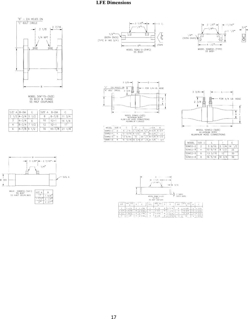
17 LFE Dimensions 17
Laminar Flow Elements
 Laminar Flow Elements Meriam Laminar Flow Elements (LFEs) are excellent for measuring low gas flow rates from 0.2 SCCM up to 2250 SCFM. They are inherently accurate and repeatable and are calibrated traceable
Technical & Sizing Bulletin for Meriam LFEs. Laminar Flow Elements
 Technical & Sizing Bulletin for Meriam LFEs Laminar Flow Elements What they are... Meriam Laminar Flow Elements are gas volume rate of flow differential producers operating on capillary flow principles.
Meriam Instrument LFE Data Sheet
 1. AIR FLOW IN SCFM AT STANDARD CONDITIONS OF 29.92 AND 70 F. SCFM = Standard cubic feet per minute. ACFM = Actual cubic feet per minute CFM = Cubic feet per minute. When the flowing gas is air and the
MTI10 Insertion and MTL10 In-line Thermal Mass Flowmeter and Temperature Transmitter
 Thermal Mass meter and Temperature Transmitter Description The MTI10 insertion thermal mass flowmeter and the MTL10 in-line thermal mass flowmeter provide accurate mass flow measurement of clean, dry gases
FMA 3100/3100ST/3300/3300ST Series Thermal Mass Flow Sensors and Meters
 FMA 3100/3100ST/3300/3300ST Series Thermal Mass Flow Sensors and Meters M-4270/0707, pg. 2 of 29 READ THIS MANUAL COMPLETELY BEFORE ATTEMPTING TO CONNECT OR OPERATE YOUR FLOW SENSOR. FAILURE TO DO SO MAY
The Fundamentals of Gas Flow Calibration
 The Fundamentals of Gas Flow Calibration Application Note Introduction Understanding the fundamentals of gas flow calibration is essential for evaluating calibration systems, estimating the magnitude of
SIZING AND CAPACITIES OF GAS PIPING
 APPENDIX A (IFGS) SIZING AND CAPACITIES OF GAS PIPING (This appendix is informative and is not part of the code.) A.1 General. To determine the size of piping used in a gas piping system, the following
The Unique Accelabar Flow Meter
 The Unique Accelabar Flow Meter The Accelabar is a new and unique flow meter that combines two differential pressure technologies to produce operating ranges never before attainable in a single flow meter.
Tadahiro Yasuda. Introduction. Overview of Criterion D200. Feature Article
 F e a t u r e A r t i c l e Feature Article Development of a High Accuracy, Fast Response Mass Flow Module Utilizing Pressure Measurement with a Laminar Flow Element (Resistive Element) Criterion D200
TELEDYNE HASTINGS INSTRUMENTS
 TELEDYNE HASTINGS INSTRUMENTS MODELS Model HFM-200 with LFE (Laminar Flow Element) FEATURES Range 25 to 15,000 slm (N 2 Equivalent) Accuracy in Nitrogen ±1% of Full scale Modular Construction NIST Traceable
Michael Montgomery Marketing Product Manager Rosemount Inc. Russ Evans Manager of Engineering and Design Rosemount Inc.
 ASGMT / Averaging Pitot Tube Flow Measurement Michael Montgomery Marketing Product Manager Rosemount Inc. Russ Evans Manager of Engineering and Design Rosemount Inc. Averaging Pitot Tube Meters Introduction
Typical Aluminum GFM Mass Flow Meter
 MASS FLOW METERS Design Features n Rigid metallic construction. n Maximum pressure of 1000 psig (70 bars). n Leak integrity 1 x 10⁻⁹ of helium. n NIST traceable certification. n Built-in tiltable LCD readout.
Aeration Air & Digester Gas Flow Metering Using Thermal Mass Technology. HWEA 2011 Conference Craig S. Johnson
 Aeration Air & Digester Gas Flow Metering Using Thermal Mass Technology HWEA 2011 Conference Craig S. Johnson Presentation Overview Introduction Aeration Air & Digester gas challenges Gas flow metering
Equivalents & Conversion Factors 406 Capacity Formulas for Steam Loads 407 Formulas for Control Valve Sizing 408-409
 Engineering Data Table of Contents Page No. I II Formulas, Conversions & Guidelines Equivalents & Conversion Factors 406 Capacity Formulas for Steam Loads 407 Formulas for Control Sizing 408-409 Steam
Turbine Flowmeters for Gas Applications
 Turbine Flowmeters for Gas Applications Description Flow Technology s FT Series turbine flowmeters utilize a proven flow measurement technology to provide exceptionally reliable digital outputs. Because
PIEZOMETER AIRFLOW MEASURING RING
 PIEZOMETER AIRFLOW MEASURING RING M.K. Plastics is pleased to introduce The Piezometer Airflow Measuring Ring, now available as an accessory for our steel Axijet fans. The system consists of a Piezometer
Thermal Dispersion Mass Flow
 Thermatel Thermal Dispersion Mass Flow Measurement Handbook Table of Contents Introduction...1 What is Mass Flow Measurement?...1 Types of Flow Transmitters...4 Differential Pressure...4 Orifice...4 Venturi...6
SIZING AND CAPACITIES OF GAS PIPING
 CALIFORNIA RESIDENTIAL CODE MATRIX ADOPTION TABLE APPENDIX A SIZING AND CAPACITIES OF GAS PIPING (Matrix Adoption Tables are non-regulatory, intended only as an aid to the user. See Chapter 1 for state
A LAMINAR FLOW ELEMENT WITH A LINEAR PRESSURE DROP VERSUS VOLUMETRIC FLOW. 1998 ASME Fluids Engineering Division Summer Meeting
 TELEDYNE HASTINGS TECHNICAL PAPERS INSTRUMENTS A LAMINAR FLOW ELEMENT WITH A LINEAR PRESSURE DROP VERSUS VOLUMETRIC FLOW Proceedings of FEDSM 98: June -5, 998, Washington, DC FEDSM98 49 ABSTRACT The pressure
RITTER Multiple Sonic Nozzle Calibration System
 RITTER Multiple Sonic Nozzle Calibration System »Wouldn t it be great to eliminate doubtful measurement results by using proven measurement technology? Providing the most precise results ensures and increases
T U R B I N E G A S M E T E R
 TURBINE GAS METER TURBINE GAS METER CGT 1 2 3 4 5 6 7 Design and function page 2 General technical data page 3 Measurement outputs page 4 Dimensions and weights page 5 Performance page 7 Pressure loss
Grant Agreement No. 228296 SFERA. Solar Facilities for the European Research Area SEVENTH FRAMEWORK PROGRAMME. Capacities Specific Programme
 Grant Agreement No. 228296 SFERA Solar Facilities for the European Research Area SEVENTH FRAMEWORK PROGRAMME Capacities Specific Programme Research Infrastructures Integrating Activity - Combination of
Dew Point Tester. Instruction Manual. CVS Regular Chiller Model A-2. CVS Regular Chiller Model A-2
 Instruction Manual Dew Point Tester The CVS Dew Point Tester is a chilled mirror apparatus, which operates by attaining the conditions necessary by the definition of dew point. When a gas is cooled out
FORMATION DAMAGE AND WELL TREATMENT SYSTEM
 FORMATION DAMAGE AND WELL TREATMENT SYSTEM FDWTS-10K Includes ability to test Liquid Permeability & Gas Permeability Fines migration & critical velocity Static Filtration Drilling mud invasion evaluation
Valve Sizing. Te chnic al Bulletin. Flow Calculation Principles. Scope. Sizing Valves. Safe Product Selection. www.swagelok.com
 www.swagelok.com Valve Sizing Te chnic al Bulletin Scope Valve size often is described by the nominal size of the end connections, but a more important measure is the flow that the valve can provide. And
General Purpose Thermal Mass Flowmeter Model 4140/4143
 Mass Flowmeters General Purpose Thermal Mass Flowmeter Model 4140/4143 Operation and Service Manual 1980383, Revision D January 2009 Mass Flowmeters General Purpose Thermal Mass Flowmeter Model 4140/4143
Sierra 820 Series Top-Trak ª Mass Flow Meters. Instruction Manual Part Number IM-82 Revision C 06-99
 Table of Contents Sierra 820 Series Top-Trak ª Mass Flow Meters Instruction Manual Part Number IM-82 Revision C 06-99 5 Harris Court, Building L Monterey, CA 93940 (831) 373-0200 (800) 866-0200 Fax (831)
INSTRUCTIONS FOR HOW TO PROPERLY SELECT A FAN OR BLOWER
 INSTRUCTIONS FOR HOW TO PROPERLY SELECT A FAN OR BLOWER The instructions that follow are to assist you in completing the information required when making a fan or blower selection. If you need additional
FLR 1000 & 1000-BR Series Flow Sensors & Meters For Gases
 FLR 1000 & 1000-BR Series Flow Sensors & Meters For Gases READ THIS MANUAL COMPLETELY BEFORE ATTEMPTING TO CONNECT OR OPERATE YOUR FLOW SENSOR. FAILURE TO DO SO MAY RESULT IN INJURY TO YOU OR DAMAGE TO
Energy and Flow Measurement for Hydronic Systems
 Energy and Flow Measurement for Hydronic Systems Presented By: George Szyszko Applications Consultant MCR for ONICON Incorporated Why Measure Thermal Energy? To control something, you must first measure
For Multi-Parameter Meters see mvx
 BULLETIN BULLETIN EM20607 VORTEX IN-LINE FLOW METERS Design Features For Multi-Parameter Meters see m Principles of Operation n No moving parts to wear or fail. n Electronics can be remotely mounted up
Advances in Thermal Dispersion Mass Flow Meter Accuracy
 Advances in Thermal Dispersion Mass Flow Meter Accuracy By Dan McQueen President Fluid Components International (FCI) Advances in Thermal Dispersion Mass Flow Meter Accuracy By Dan McQueen President Fluid
Custody Transfer Measurement. with the V-Cone Flowmeter
 Custody Transfer Measurement with the V-Cone Flowmeter Stephen A. Ifft McCrometer Inc. Hemet, California, USA Abstract This paper will discuss the approval of the McCrometer V-Cone flowmeter for custody
SIZING AND CAPACITIES OF GAS PIPING (Not Adopted by the State of Oregon)
") (IFGS) SIZING AND CAPACITIES OF GAS PIPING (Not Adopted by the State of Oregon) (This appendix is informative and is not part of the code. This appendix is an excerpt from the 2006 International Fuel Gas
(IFGS) SIZING AND CAPACITIES OF GAS PIPING (Not Adopted by the State of Oregon) (This appendix is informative and is not part of the code. This appendix is an excerpt from the 2006 International Fuel Gas
Many Products...One Source
 PRESSURE GAUGES Dedicated Sales Rep for Your Area 97%Fill Rate Shipping within 24 Hours State of the Art Warehouse System Technical Support Quality Control Program 25 Whaley Avenue Milverton, Ontario N0K
Side-Trak 830/840. Process Gas Mass Flow Meters and Controllers. www.sierrainstruments.com
 Process Gas Mass Flow Meters and Controllers Features n Direct monitoring of mass flow eliminates need for ancillary pressure and temperature sensing n Patented straight sensor tube with access ports permits
MODEL TEG-F20. Specification Sheet. TEG-F20 Specification Sheet Ver. 2011-0310. Copyright(C) 2011 Tsukasa Sokken Co., Ltd.
 2011 Tsukasa Sokken Co., Ltd.") Direct EGR Flow Meter MODEL TEG-F20 Specification Sheet TEG-F20 Specification Sheet Ver. 2011-0310 Copyright(C) 2011 Tsukasa Sokken Co., Ltd. 1. Overview Sokken model TEG series is an EGR Flow meter to
Direct EGR Flow Meter MODEL TEG-F20 Specification Sheet TEG-F20 Specification Sheet Ver. 2011-0310 Copyright(C) 2011 Tsukasa Sokken Co., Ltd. 1. Overview Sokken model TEG series is an EGR Flow meter to
Specifications - Installation and Operating Instructions Ø5 [127.00] 17/64 [6.91] 1-59/64 [48.89]
![Specifications - Installation and Operating Instructions Ø5 [127.00] 17/64 [6.91] 1-59/64 [48.89]](/thumbs/40/20993241.jpg "Specifications - Installation and Operating Instructions Ø5 [127.00] 17/64 [6.91] 1-59/64 [48.89]") Bulletin P-DM-1100 Series DM-1000 DigiMag Digital Differential Pressure Gage Specifications - Installation and Operating Instructions PRESSURE CONNECTIONS 21/64 [8.59] LONG Ø5 [127.00] 4-31/64 [113.89]
Bulletin P-DM-1100 Series DM-1000 DigiMag Digital Differential Pressure Gage Specifications - Installation and Operating Instructions PRESSURE CONNECTIONS 21/64 [8.59] LONG Ø5 [127.00] 4-31/64 [113.89]
Fundamentals of Mass Flow Control
 Fundamentals of Mass Flow Control Critical Terminology and Operation Principles for Gas and Liquid MFCs A mass flow controller (MFC) is a closed-loop device that sets, measures, and controls the flow of
Vogt Valves The Connection Bulletin for Forged Steel Flow Control Valves CB 15
 The Connection Bulletin for Forged Steel Flow Control Valves CB 15 Flow Control Division Forged Steel Flow Control Valves GRADUATED DIAL AND INDICATOR FULLY GUIDED V-PORT THROTTLING DISC AND INTEGRAL HARD
Technical Information
 Determining Energy Requirements - & Gas Heating & Gas Heating and gas heating applications can be divided into two conditions, air or gas at normal atmospheric pressure and air or gas under low to high
ACFM vs. SCFM vs. ICFM Series of Technical White Papers from Ohio Medical Corporation
 ACFM vs. SCFM vs. ICFM Series of Technical White Papers from Ohio Medical Corporation Ohio Medical Corporation 1111 Lakeside Drive Gurnee, IL 60031 Phone: (800) 448-0770 Fax: (847) 855-6304 info@ohiomedical.com
Powers Controls Free Energy Band TH 193 HC Heating/Cooling Room Thermostat
 Document No. 155-068P25 TH 193-4 Powers Controls Free Energy Band TH 193 HC Heating/Cooling Room Thermostat 50 60 70 80 70 TH0356R1 60 80 POWERS Description The TH 193 HC thermostats are proportional dual
red-y smart series product information Thermal Mass Flow Meters and Controllers for Gases
 red-y smart series product information Thermal Mass Flow Meters and Controllers for Gases Reliable and accurate: Thermal Mass Flow Meters and Controllers Reliable technology and industry standard interfaces
Sentinel LCT. Panametrics Ultrasonic Flowmeter for Liquid Custody Transfer Measurement. GE Measurement & Control Solutions. Benefits.
 GE Measurement & Control Solutions Sentinel LCT Panametrics Ultrasonic Flowmeter for Liquid Custody Transfer Measurement Benefits Extremely reliable and highly accurate flowmeter, designed specifically
Precision Mass Flow Metering For CVD Applications.
 Precision Mass Flow Metering For CVD Applications. Ir. H.J. Boer Research Department of Bronkhorst High-Tech B.V. Nijverheidsstraat 1A, 7261 AK Ruurlo The Netherlands. Tel: +31 (0)573 458800 Fax: +31 (0)573
PPB Dissolved Oxygen Measurement - Calibration and Sampling Techniques
 PPB Dissolved Oxygen Measurement - Calibration and Sampling Techniques Introduction The amount of dissolved oxygen in process water is continually gaining importance in many industries as a critical parameter
Air Eliminators and Combination Air Eliminators Strainers
 Description Air Eliminators and Combination Air Eliminator Strainers are designed to provide separation, elimination and prevention of air in piping systems for a variety of installations and conditions.
DICKSON PR100/PR300/PR500 DICKSON. Pressure Logger Operation. Contents:
 PR100/PR300/PR500 Pressure Logger Operation Contents: Product Applications and Useful Features Product Specifications Operating Instructions / Getting Started DicksonWare Software Specifications Product
COMBIMASS. Technical Data COMBIMASS eco-bio +
 COMBIMASS Technical Data THE SYSTEM COMBIMASS The field transmitters of the COMBIMASS eco series are suitable for gas flow measurement and cover a wide range of different applications. The instruments
= 800 kg/m 3 (note that old units cancel out) 4.184 J 1000 g = 4184 J/kg o C
 4.184 J 1000 g = 4184 J/kg o C") Units and Dimensions Basic properties such as length, mass, time and temperature that can be measured are called dimensions. Any quantity that can be measured has a value and a unit associated with it.
Units and Dimensions Basic properties such as length, mass, time and temperature that can be measured are called dimensions. Any quantity that can be measured has a value and a unit associated with it.
EASIDEW PORTABLE HYGROMETER INSTALLATION, OPERATION AND MAINTENANCE MANUAL
 EASIDEW PORTABLE HYGROMETER INSTALLATION, OPERATION AND MAINTENANCE MANUAL Issue February 2004 2 TABLE OF CONTENTS SECTION PAGE 1. INTRODUCTION 3 1.1 General 3 1.2 Ceramic Sensing Element 3 1.3 Calibration
Electromagnetic Flow Meter
 Electromagnetic Flow Meter Description The EL 2200 series of electromagnetic sensors represent the state of the art for the accurate measurement for water cycle and process applications. Flow meters are
SERIES ASM NEOPRENE/EPMD FLANGED SINGLE SPHERE CONNECTOR CONNECTORS. Pressures to 225 PSIG (15.51 barg) Temperatures to 230ºF (110ºC)
 Temperatures to 230ºF (110ºC)") APPLICATIONS Process Industry Weak Acids Alkalies Compressed Air Pulp & Paper MODELS ASM - Flanged Connection OPTIONS Control Rods Oil & Gas Water & Waste Pump suction & discharge Sea water Chemical lines
APPLICATIONS Process Industry Weak Acids Alkalies Compressed Air Pulp & Paper MODELS ASM - Flanged Connection OPTIONS Control Rods Oil & Gas Water & Waste Pump suction & discharge Sea water Chemical lines
Powers Controls TH 192 HC Heating/Cooling Room Thermostat
 Powers Controls TH 192 HC Heating/Cooling Room Thermostat Technical Instructions Document No. 155-066P25 TH 192-2 50 60 70 80 70 TH0356R1 60 80 POWERS Description The TH 192 HC thermostats are proportional
Advanced Differential Pressure Flowmeter Technology V-CONE FLOW METER TECHNICAL BRIEF
 Advanced Differential Pressure Flowmeter Technology V-CONE FLOW METER TECHNICAL BRIEF Table of Contents Section 1 - General Introduction 1.1 1 Principles Of Operation 1.2 1 Reshaping The Velocity Profile
The Versatile Differential Pressure Transmitter. By David Gunn Honeywell Process Solutions
 The Versatile Differential Pressure Transmitter By David Gunn Honeywell Process Solutions The Versatile Differential Pressure Transmitter 2 Table of Contents Abstract... 3 Pressure Fundamentals... 3 Applications...
Establishment of the Gas Flow Calibration Facility at CSIR-NPL, India
 Establishment of the Gas Flow Calibration Facility at CSIR-PL, India Speaker: Shiv Kumar Jaiswal Fluid Flow Measurement Standards CSIR-ational Physical Laboratory (PLI) Dr. K.S. Krishnan Road ew Delhi
289 Series Spring-Loaded Relief Valves
 October 14 89 Series Spring-Loaded Relief Valves W187_1 W1871 TYPE 89L 1 NPT TYPES 89H AND 89HH W187 NPT TYPE 89H W187_ TYPES 89U AND 89A Figure 1. Types 89H, 89L and 89U Relief Valves Introduction The
DICKSON PW4 DICKSON. Pressure Chart Recorders. Applications & Specifications. Product. Getting Started, Charts & Accessories.
 PW4 Pressure Chart Recorders Contents: Applications and Useful Features Operating Instructions / Getting Started Calibrations Troubleshooting Warranty / Factory Service & Applications The PW4 Weather Resistant
Method to Determine PERFORMANCE OF INDIRECT-FIRED WATER HEATERS March 2003 Edition
 Supplement to TESTING STANDARD Method to Determine PERFORMANCE OF INDIRECT-FIRED WATER HEATERS March 2003 Edition [NOTE: This supplement incorporates testing and calculations to determine heat source friction
Model 111 Mass Flow Instruments
 111 Mass Instruments Porter Mass products reflect over four decades of experience in the design and manufacture of precision instruments for the measurement and control of gas flow. They incorporate design
WD600 STEAM TRAPS. Thermodynamic Steam Trap
 WD600 Watson McDaniel reserves the right to change the designs and/or materials of its products without notice. 2010 Watson McDaniel Company WD600, WD600L Sizes 3/8, 1/2, 3/4, 1 NPT Material Stainless
2-Port Self-acting Temperature Control Valve Selection for Heating and Cooling Applications
 Page 1 of 12 TI-S21-07 CH Issue 1 Cert. No. LRQ 0963008 ISO 9001 2-Port Self-acting Temperature Control Valve Selection How to select a system Valve selection: 1. Is the application for heating or cooling?
Toroidal Conductivity Sensor
 Instruction Sheet PN 51A-/rev.C June 2012 Toroidal Conductivity Sensor For additional information, please visit our website at www.emersonprocess.com/rosemountanalytical.com SPECIFICATIONS Wetted Materials:
SUMMARY of PRODUCTS. HVAC Systems Control Airflow, Space, & Building Pressurization. Accurate airflow measurement for demanding applications
 SUMMARY of PRODUCTS HVAC Systems Control Airflow, Space, & Building Pressurization Accurate airflow measurement for demanding applications Airflow Measuring Stations FAN-E AIRFLOW MEASURING STATION. The
Model 1210C Battery Powered Pump Shown. Description
 12 Volt DC Rotary Vane Pump Series 1200C Model 1210C Battery Powered Pump Shown Description of Included Models Model Number FR1205C FR1210C FR1211C FR2410C FR2411C Description Basic 12 volt DC pump with
DEVELOPMENT OF HIGH SPEED RESPONSE LAMINAR FLOW METER FOR AIR CONDITIONING
 DEVELOPMENT OF HIGH SPEED RESPONSE LAMINAR FLOW METER FOR AIR CONDITIONING Toshiharu Kagawa 1, Yukako Saisu 2, Riki Nishimura 3 and Chongho Youn 4 ABSTRACT In this paper, we developed a new laminar flow
CO 2 41.2 MPa (abs) 20 C
 20 C") comp_02 A CO 2 cartridge is used to propel a small rocket cart. Compressed CO 2, stored at a pressure of 41.2 MPa (abs) and a temperature of 20 C, is expanded through a smoothly contoured converging nozzle
comp_02 A CO 2 cartridge is used to propel a small rocket cart. Compressed CO 2, stored at a pressure of 41.2 MPa (abs) and a temperature of 20 C, is expanded through a smoothly contoured converging nozzle
1805 Series Relief Valves
 October 2011 1805 Series Relief Valves P1026 1805G Type 1805-2 Type 1805-4 Figure 1. Typical 1805 Relief Valves Introduction The 1805 Series relief valves are designed for use in farm tap applications
Laminar and Turbulent flow. Flow Sensors. Reynolds Number. Thermal flow Sensor. Flow and Flow rate. R = Mass Flow controllers
 Flow and Flow rate. Laminar and Turbulent flow Laminar flow: smooth, orderly and regular Mechanical sensors have inertia, which can integrate out small variations due to turbulence Turbulent flow: chaotic
In-Line Electronic Flow Switches
 In-Line Electronic Flow Switches Industries Petrochemical Refining Oil Production Water Treatment Pharmaceutical Food and Beverage Pulp and Paper Power Production Gas Processing Mining Biotechnology Semiconductor
M SERIES REFRIGERANT COIL MODULE REFRIGERANT COILS for R-22, R-407C, R-410A
 Bulletin 20-20.2 / July 2012 M SERIES REFRIGERANT COIL MODULE REFRIGERANT COILS for R-22, R-407C, R-410A ➀ ➁ ➂ Model Number Key M 2430 C L 1 - A - ➀ Unit Type M=Modular Nominal Capacity 2430=24000 to 30000
07 21 19 Guide Specification STAYFLEX CORROSION CONTROL AND THERMAL INSULATION SYSTEM
 07 21 19 STAYFLEX CORROSION CONTROL AND THERMAL INSULATION SYSTEM 7819 Broadview Road Cleveland, OH 44131 800-522-4522 February, 2011 SPEC NOTE: This guide specification is intended for use when specifying
GENERAL PURPOSE THERMAL MASS FLOWMETER MODEL 4140/4143
 GENERAL PURPOSE THERMAL MASS FLOWMETER MODEL 4140/4143 OPERATION AND SERVICE MANUAL P/N 1980383, REVISION G FEBRUARY 2016 GENERAL PURPOSE THERMAL MASS FLOWMETER MODEL 4140/4143 OPERATION AND SERVICE MANUAL
Standard Pneumatic Test Procedure Requirements for Piping Systems
 the pressure equipment safety authority Standard Pneumatic Test Procedure Requirements for Piping Systems AB-522 Edition 2, Rev. 0 Issued 2012-06-28 Table of Contents FOREWORD... 3 1.0 INTRODUCTION...
Powers Controls TH 192 S Single Temperature Room Thermostat
 Technical Instructions Document No. 155-065P25 TH 192-1 Powers Controls TH 192 S Single Temperature Room Thermostat 50 60 70 80 TH0355R1 70 80 POWERS Description The TH 192 S thermostats are proportional
1. A belt pulley is 3 ft. in diameter and rotates at 250 rpm. The belt which is 5 ins. wide makes an angle of contact of 190 over the pulley.
 Sample Questions REVISED FIRST CLASS PARTS A1, A2, AND A3 (NOTE: these questions are intended as representations of the style of questions that may appear on examinations. They are not intended as study
Decision. Aerospace Control Products, Inc. File: B-274868. Date: January 9, 1997
 OF COMPTROLLER T H E UN IT ED GENERAL S TAT ES Comptroller General of the United States Washington, D.C. 20548 Decision DOCUMENT FOR PUBLIC RELEASE A protected decision was issued on the date below and
Agilent Veriflow 500 Electronic Flowmeter. Flow Range: 1 500 sccm. Operation Guide. Agilent Technologies
 Agilent Veriflow 500 Electronic Flowmeter Flow Range: 1 500 sccm Operation Guide Agilent Technologies Notices Agilent Technologies, Inc. 2006 No part of this manual may be reproduced in any form or by
WIKA INSTRUMENT CORPORATION
 WIKA INSTRUMENT CORPORATION Instruction Manual GAUGE PRESSURE INDICATOR Series 1500 Series 1000 Series 300 WIKA Instrument Corporation 1000 Wiegand Boulevard Lawrenceville, GA 30043 1-888-945-2872 http://www.wika.com
SANITARY GRAVITY SEWER LINE TESTING. B. Section 02732 CCTV Inspection of Gravity Sewer Lines
 PART 1 GENERAL 1.1 SECTION INCLUDES A. Low Pressure Air Test B. Deflection Test 1.2 RELATED SECTIONS A. Section 02730 Sanitary Gravity Sewer Lines B. Section 02732 CCTV Inspection of Gravity Sewer Lines
COMPRESSED AIR ULTRASONIC LEAK DETECTION GUIDE
 COMPRESSED AIR ULTRASONIC LEAK DETECTION GUIDE COMPRESSOR ROOM INTAKE FILTER AIR COMPRESSOR AFTERCOOLER MOISTURE SEPARATOR RECEIVER MAIN FILTER SECONDARY FILTERS AND LUBRICATORS V 1406R Increased Productivity
Thermal Mass Flow Meter (Series MST)
") Overview MaxiFlo TM MST series Thermal Mass Flow Meter is the instrument of choice for reliable and accurate measurement of mass flows for various gases. It measures the mass flow of gas based on constant
Overview MaxiFlo TM MST series Thermal Mass Flow Meter is the instrument of choice for reliable and accurate measurement of mass flows for various gases. It measures the mass flow of gas based on constant
Pressure calibration equipment
 Pressure calibration equipment Pressure calibration evolution 1925 Westertoren in Amsterdam 30 meter mercury column (±40 bar) 1950 comparison test pump 21 st century Stiko gas driven differential deadweight
Experiment # 3: Pipe Flow
 ME 05 Mechanical Engineering Lab Page ME 05 Mechanical Engineering Laboratory Spring Quarter 00 Experiment # 3: Pipe Flow Objectives: a) Calibrate a pressure transducer and two different flowmeters (paddlewheel
sensors ISSN 1424-8220 www.mdpi.com/journal/sensors
 Sensors 2010, 10, 10560-10570; doi:10.3390/s101210560 OPEN ACCESS sensors ISSN 1424-8220 www.mdpi.com/journal/sensors Article A New Approach to Laminar Flowmeters Fernando Lopez Pena *, Alvaro Deibe Diaz,
Effects of Atmospheric Pressure on Gas Measurement
 Effects of Atmospheric Pressure on Gas Measurement Class # 1390.1 March 2012 / White paper by Denis Rutherford Regional Sales Manager Central US Schneider Electric Telemetry & Remote SCADA Solutions 6650
Source Sampling Manual Volume II
 Source Sampling Manual Volume II December, 1980 Revisions: May, 1981 January, 1992 April, 2015 Operations Division 811 SW 6 th Avenue Portland, OR 97204 Phone: 503-229-5696 800-452-4011 Fax: 503-229-5850
Air Pollution Control Division. Technical Services Program
 Page 1 of 10 Air Pollution Control Division Technical Services Program APPENDIX PM4 STANDARD OPERATING PROCEDURE FOR THE DETERMINATION OF PM 10 AND PM 2.5 IN AMBIENT AIR USING A GRIMM EDM 180 Page 2 of
PRODUCT REVIEW. Flowmeters and Controllers. Vacuum Instrumentation
 PRODUCT REVIEW Flowmeters and Controllers Vacuum Instrumentation TELEDYNE HASTINGS VACUUM Instrumentation Thermocouple Gauges ANALOG METERS AND CONTROLLERS - VT Series Three Standard Ranges: 0 to 100 mtorr,
RI-215A Operator s Manual. Part Number: 71-0045RK Revision 0 Released: 10/3/05
 RI-215A Operator s Manual Part Number: 71-0045RK Revision 0 Released: 10/3/05 Warranty RKI Instruments, Inc., warrants gas alarm equipment sold by us to be free from defects in materials and workmanship,
Model DE-3 Air Release Head
 SPECIFICATIONS MEASUREMENT SOLUTIONS Model Air Release Head Bulletin SS03037 Issue/Rev. 0.2 (10/15) We put you first. And keep you ahead. SMITH METER AIR ELIMINATOR The Smith Meter Model Air Release Heads
SPECIFICATION DIVISION 22 SECTION DESCRIPTION DIVISION 22 PLUMBING SECTION 220519 - THERMOMETERS, PRESSURE GAUGES, AND ACCESSORIES
 ARCHITECTURE, ENGINEERING AND CONSTRUCTION P00000000 0000 DOCUMENTS ARCHITECTURE & ENGINEERING 326 East Hoover, Mail Stop B Ann Arbor, MI 48109-1002 Phone: 734-764-3414 Fax: 734-936-3334 SPECIFICATION
Charts (Section XI) www.accordintl.com Ph. (713) 641-2288 Fax (713) 641-3636 Main PAGE #
 www.accordintl.com Ph. (713) 641-2288 Fax (713) 641-3636 Main PAGE #") Charts (Section XI) Part No. Description Page No. Fraction, Decimal, and Millimeter Conversion Chart 2 Measurement Chart (Metric & Standard) 3 Standard (ANSI B16.5) Flange Dimension Chart 4 Metric Flange
Charts (Section XI) Part No. Description Page No. Fraction, Decimal, and Millimeter Conversion Chart 2 Measurement Chart (Metric & Standard) 3 Standard (ANSI B16.5) Flange Dimension Chart 4 Metric Flange
ENDURANCE Conductivity Sensors
 Instruction Manual 400 and 400VP LIQ_MAN_ABR_400_400VP December 2013 ENDURANCE Conductivity Sensors For additional information, please refer visit our website at www.rosemountanalytical.com. CAUTION Sensor/Process
KNC Model 3666 Automatic Pressure Calibration System
 KNC Model 3666 Automatic Pressure Calibration System Product Description The Model 3666 Automatic Pressure Calibration (APC) System by King Nutronics Corporation is a portable secondary standards laboratory
Index 11.1. Page. Pumping Systems...11.2-11.4 Intensifiers...11.5 Gas Boosters...11.6-11.7 High Pressure Generators...11.8-11.9
 Pumping Systems, Intensifiers, Gas Boosters and High Pressure Generators High Pressure Equipment Company produces a number of components and systems for general industrial, elevated pressure applications.
Trace Dissolved Oxygen Sensor
 Instruction Sheet PN 51A-499ATRDO/rev.G September 2010 Model 499A TrDO Trace Dissolved Oxygen Sensor For additional information, please visit our website at www.emersonprocess.com/raihome/liquid/. CAUTION
Relative Humidity Sensors, Transmitters and Calibration Products Relative Humidity Measurement and Calibration
 Relative Humidity Measurement and Calibration The widest range of humidity products from a pioneer of RH sensor development The best in Relative Humidity technology to optimize your process Whether you