SC Installation, Operation & Application Guide
|
|
|
- Shannon Ray
- 9 years ago
- Views:
Transcription
1 SC 2201 Manual Changeover Non-Programmable Hardwired Non-Programmable Electronic Thermostat For use with Heat Pumps Up to 2-Stage Heat, 2-Stage Cool 30-Minute Power Loss Memory etention For use with 24 VAC Systems Installation, peration & Application uide For more information on our complete range of American-made products plus wiring diagrams, troubleshooting tips and more, visit us at

2 Table of Contents Parts Diagram...1 Specifications... 2 Features/Benefits... 2 Package Contents/Tools equired... 2 Important Safety Information... 3 eneral Description... 2 To emove Existing Thermostat... 4 eplacing Wiring Labels... 4 To Install Thermostat... 5 Testing the Thermostat... 6 LED Indicators... 8 peration...9 Wiring Diagrams Carrier Split Stream Condensers Coleman 3000 Series...12 Comfortmaker CYC Series...13 Heil-Quaker Series and PH50 Series...14 Payne eliant and Endura Model...15 heem/uud: -PB, -PFA, -PCB, -PLA, and -PKA Series...16 oodman, Janitrol, Trane/American Standard...17 York -E1CS, -E1FB, E1FH...18 Lennox CB Lennox HP19 and HP Lennox HP21 with CB21 PCB...21 Lennox HP22 with CB19 PCB...22 FHP 1 Stage...23 FHP 2 Stage...24 Troubleshooting...25 CAUTIN!: This thermostat should be installed by trained technicians only. Adhere to all local and national codes. Disconnect all power to the system before installing, removing, or cleaning.

3 Parts Diagram 1
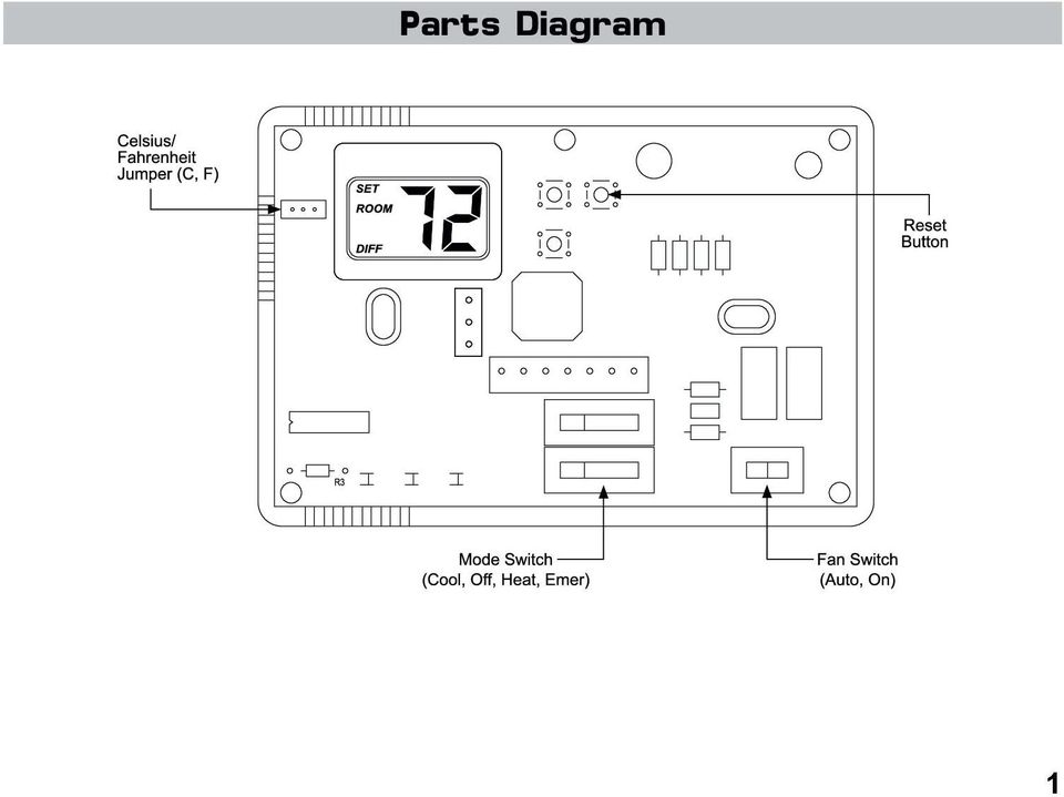
4 Specifications Input: Voltage: 24 VAC (18-30 VAC) utput: Maximum: 1 amp maximum load per terminal (4 amp total maximum load for all terminals) Temperature anges: Temperature control range: 45 F to 90 F (7 C to 32 C) Accuracy: ± 1 F (± 0.5 C) Differential range: 1 F to 3 F (0.5 C to 1.5 C) System configurations: Multi-stage heat pump (two-stage heat, two-stage cool) Terminations:, C, E, Y1, Y2,, B,, L, W2 Second stage activation in heat mode: 2 below first stage (not adjustable) Second stage activation in cool mode: 2 above first stage (not adjustable) oom temperature setpoint oom temperature Temperature differential setting SET M DIFF Features/Benefits Multi-stage heating/cooling control Multi-colored LED indicators for system status Zone system compatible as a master thermostat Fahrenheit display and operation can be changed to Celsius Adjustable temperature differential: 1 F to 3 F (0.5 C to 1.5 C) Automatic heating system shutdown if temperature exceeds 90 F (32 C) 30-minute power interruption memory retention eset button for differential temperature adjustment Independent setpoints for heat and cool 2 Package Contents/Tools equired Package includes: SimpleComfort 2201 non-programmable thermostat on base, thermostat cover, wiring labels, screws and wall anchors, Installation, peration and Application uide. Tools required for installation: Drill with 3/16 bit, hammer, screwdriver.
 oom temperature setpoint oom temperature Temperature differential setting SET M DIFF Features/Benefits Multi-stage")
5 Important Safety Information Always turn off power at the main power source by unscrewing fuse or switching circuit breaker to the off position before installing, removing, cleaning, or servicing this thermostat ead all of the information in this manual before installing this thermostat This thermostat should be installed only by a professional contractor This is a 24 VAC low-voltage thermostat; do not install on voltages higher than 30 VAC All wiring must conform to local and national building and electrical codes and ordinances Do not switch system to cool if the outdoor temperature is below 50 F (10 C); this can damage the air conditioning system and may cause personal injury The thermostat will not control your heating/air conditioning system without power; it requires a continuous 24 VAC circuit for proper system control Use this thermostat only as described in this manual While cleaning, do not get soap directly on thermostat switches or LCD readout; only use a damp cloth with a mild soap to wipe outside of thermostat cover eneral Description The SimpleComfort 2201 is intended to operate and is compatible with 24 VAC residential heat pumps with up to 2-stage heat/2-stage cool. It will operate with multi-stage heat pump systems that are manual changeover and have auxiliary or emergency heating. There are no optional items required for standard installations. This thermostat is also compatible as a master thermostat in zoned system applications. The SimpleComfort 2201 will automatically control the heat and/or air conditioning system. When used properly, this thermostat can reduce heating and cooling costs throughout the year. 3
; this can damage the air conditioning system and may cause personal injury The thermostat will not control your heating/air conditioning system without power; it")
6 To emove Existing Thermostat ELECTICAL SHCK HAZAD Turn off power at the main service panel by removing the fuse or switching the appropriate circuit breaker to the ff position before removing the existing thermostat. 1. Turn off power to the heating and cooling system by removing the fuse or switching off the appropriate circuit breaker. 2. emove cover of old thermostat. This should expose the wires. 3. Label the existing wires with the enclosed wire labels before removing wires. See table below for old and new label identification. 4. After labeling wires, remove wires from wire terminals. 5. emove existing thermostat base from wall. 6. efer to the following section for instructions on how to install this thermostat. eplace the old labels with the enclosed new labels: eplacing Wiring Labels 4 ld New Type, V-V or V- 24 VAC, return Y, Y1 or M Y1 Stage 1 cooling/heating circuit or eversing valve (cooling mode) B B eversing valve (heat mode) or F Fan contactor circuit Y2 Y2 2nd stage cooling circuit W1, W2 or W-U W2 2nd stage heating circuit L or X L System monitor LED E E Emergency heating circuit C, X or B C 24 VAC, transformer common side

7 To Install Thermostat ELECTICAL SHCK HAZAD Turn off power at the main service panel by removing the fuse or switching the appropriate circuit breaker to the ff position before removing the existing thermostat. IMPTANT: Thermostat installation must conform to local and national building and electrical codes and ordinances. IMPTANT: This thermostat is compatible with 100% lockout systems. To reset the system, turn thermostat to ff position for at least 60 seconds. Note: Mount the thermostat about five feet above the floor. Do not mount the thermostat on an outside wall, in direct sunlight, behind a door, or in an area affected by a vent or duct. 1. Turn off power to the heating and cooling system by removing the fuse or switching off the appropriate circuit breaker. Mode Fan 2. Put Mode switch in ff position. 3. Put Fan switch in Auto position. 4. To remove cover, insert and twist a coin or screwdriver in the slots on the sides of the thermostat. Cool ff Heat Emer Auto n 5. Put thermostat base against the wall where you plan to mount it (Be sure wires will feed through the wire opening in the base of the thermostat). 6. Mark the placement of the mounting holes. 7. Set thermostat base and cover away from working area. 8. Using a 3/16 drill bit, drill holes in the places you have marked for mounting. 9. Use a hammer to tap supplied anchors in mounting holes. 10. Align thermostat base with mounting holes and feed the control wires through wire opening. 11. Use supplied screws to mount thermostat base to wall. 5

8 12. Insert stripped, labeled wires in matching wire terminals. See Wiring Diagrams section of this manual (Pages 11-24). CAUTIN!: Be sure exposed portion of wires does not touch other wires. 13. Tighten screws on terminal block. ently tug wire to be sure of proper connection. Double check that each wire is connected to the proper terminal. 14. Seal hole for wires with non-flammable putty or insulation. 15. eplace cover on thermostat by snapping it in place. 16. Turn on power to the system at the main service panel. 17. Test thermostat operation as described in the following section. Testing the Thermostat CAUTIN!: Do not switch system to cool if the outdoor temperature is below 50 F (10 C). This can damage the air conditioning system and may cause personal injury. 1. Put the Mode switch to Cool position. 2. Press the button until the temperature setting is at least 3 degrees below the room temperature. The air conditioning system and fan should turn on within a few seconds. 3. Put the Mode switch in the ff position. The air conditioning system should turn off. The fan may have a delay. Note: Pressing the eset button will bypass the 5-minute anti-short cycle compressor protection. Mode Cool ff Heat Emer Mode Cool ff Heat Emer 6
.")
9 Note: While in Cool or Heat mode, once the thermostat turns the system off, a built-in delay keeps the compressor from turning on for about 5 minutes. This protects the compressor. Mode 4. Put the Mode switch to the Heat position. 5. Press the button until the temperature setting is at least 3 degrees above room temperature. The heating system should turn on. Note: The compressor may not turn on again for 5 minutes. 6. Put the Mode switch to the ff position. The heating system should turn off. nce again the fan may have a delay. 7. Put the Fan switch to the n position. The blower fan should turn on. Cool ff Heat Emer Mode Cool ff Heat Emer Fan Auto n 8. Put the Fan switch to the Auto position. The blower fan should turn off. If all functions operate properly, the thermostat is installed correctly. If the thermostat does not operate properly: Check all wiring connections See Troubleshooting (Page 25) Auto Fan n 7

10 There are three LED indicators located on the front of the thermostat. They are designed to inform you of the following: AUX (EEN): This turns on when the auxiliary (back-up) heating is in operation. This is the second (non-economy) stage of heat. It turns on 2 degrees below first stage and is not adjustable. CHECK (ED): When this turns on, a malfunction has occurred somewhere in the heat pump system. Please contact a qualified service technician as soon as possible to check your system. EME (ED): LED Indicators This light turns on whenever the emergency heat is manually selected (system switch is in the EME position). While in the emergency heat mode, the heat pump compressor is off, and the emergency heat (same as the auxiliary heat) maintains the setpoint temperature. EME (ED) CHECK (ED) AUX (EEN) Aux Check Emer Cool ff Heat Emer Auto n 8
: LED Indicators This light turns on whenever the emergency heat is manually selected (system switch is in the EME position).")
11 peration Setting the oom Temperature (Setpoint Temperature) Step 1: Press the or button; the current temperature setpoint displays. Step 2: Press the or button until the desired temperature setpoint displays. Note: Holding down either the or button will scroll the temperature display. The new temperature setting is automatically saved. After 5 seconds, the display returns to showing the current room temperature. Setting a New Temperature Differential IMPTANT: The default temperature differential is factory set at 1 F. When your room temperature varies by 1 F, the thermostat turns your system on. If you notice your system turning on and off too frequently, increase the temperature differential accordingly. Step 1: emove cover and press eset button once. Step 2: The display will show This is the temperature differential setting. Step 3: Press the or button to adjust the temperature differential down or up. The display will return to the room temperature display five seconds after the last input. The new temperature differential setting will be saved. Differential Setting F C 1 1 F 0.5 C 2 2 F 1.0 C 3 3 F 1.5 C 9

12 Changing Fahrenheit to Celsius The temperature displays in degrees Fahrenheit as a factory set default. Follow these steps to change to degrees Celsius: Step 1: emove the cover. Step 2: Move the F/C jumper to the desired position, F or C using the center pin as a common. Step 3: Press the eset button once and reinstall the cover. Your LCD readout changes accordingly. Starting the Thermostat Step 1: Move the Fan switch into the Auto position. In Auto, indoor fan runs only during a heating or cooling cycle In N, indoor fan runs continuously Step 2: Move the Mode switch in either Cool or Heat position, depending on the season. The thermostat will now operate and maintain the room temperature at the desired setpoint. Note: When the thermostat operates the system, there is built-in compressor protection. After the compressor turns off, the system will not turn it back on for about five minutes. This protects the compressor. Fan Auto n Mode Cool ff Heat Emer 10

13 Wiring Diagrams SimpleComfort 2201 Electronic Thermostat Conversion to: Carrier Split Stream Condensers and Heat Pump Systems Y1 SimpleComfort 2201 B E W2 L C Y2 24 VAC, eturn Carrier Split Stream Low Voltage Terminal Board Y E W2 L C Compressor Contactor eversing Valve (Cooling Mode) Fan Contactor Circuit Emergency Heating Circuit 2nd Stage Heating Circuit System Monitor LED 24 VAC, Common W3 11

14 SimpleComfort 2201 Electronic Thermostat Conversion to: Coleman 3000 Series Heat Pump Systems Y1 SimpleComfort 2201 B E W2 L C Y2 24 VAC, eturn Coleman 3000 Low Voltage Terminal Board Y B E W2 L X Compressor Contactor eversing Valve (Heating Mode) Fan Contactor Circuit Emergency Heating Circuit 2nd Stage Heating Circuit System Monitor LED 24 VAC, Common 12

15 SimpleComfort 2201 Electronic Thermostat Conversion to: Comfortmaker CYC Series Heat Pump Systems Note 1: E and W2 terminals jumpered at thermostat. Note 2: W2 terminal on Comfortmaker capped at PCB. Note 2: X terminal on Comfortmaker capped at PCB. Y1 SimpleComfort 2201 B E W2 L C Y2 24 VAC, eturn Comfortmaker CYC Low Voltage Terminal Board Y W1 W2 X C Compressor Contactor eversing Valve (Cooling Mode) Fan Contactor Circuit 2nd Stage Heating Circuit utdoor Thermostat Defrost Sensor 24 VAC, Common (capped) (capped) 13
 Fan Contactor Circuit 2nd Stage Heating Circuit utdoor Thermostat Defrost Sensor 24 VAC, Common")
16 SimpleComfort 2201 Electronic Thermostat Conversion to: Heil-Quaker Series and PH50 Series Heat Pump Systems Note 1: E and W2 terminals jumpered at thermostat. Note 2: W2 terminal on Heil-Quaker capped at PCB. SimpleComfort 2201 Y1 B E W2 L C Y2 Heil-Quaker Series and PH50 Low Voltage Terminal Board Y W1 W2 C 24 VAC, eturn Compressor Contactor eversing Valve (Cooling Mode) Fan Contactor Circuit 2nd Stage Heating Circuit (Sequencer 1) 3rd Stage Heating Circuit (Sequencer 2) 24 VAC, Common (capped) 14
 Fan")
17 SimpleComfort 2201 Electronic Thermostat Conversion to: Payne eliant and Endura Model Heat Pump Systems Note 1: W3 terminal on Payne PCB capped at PCB. SimpleComfort 2201 Y1 B E W2 L C Y2 24 VAC, eturn Payne eliant and Endura Model Low Voltage Terminal Board Y E W2 L C W3 Compressor Contactor eversing Valve (Cooling Mode) Fan Contactor Circuit Emergency Heating Circuit 2nd Stage Heating Circuit System Monitor LED 24 VAC, Common 3rd Stage Heating Circuit (capped) 15
 Fan Contactor Circuit Emergency Heating Circuit 2nd Stage")
18 SimpleComfort 2201 Electronic Thermostat Conversion to: heem/uud: -PB, -PFA, -PCB, -PLA, and -PKA Series Heat Pump Systems Note 1: E and W2 terminals jumpered at thermostat. SimpleComfort 2201 Y1 B E W2 L C Y2 heem/uud: -PB, -PFA, -PCB, -PLA, and -PKA Low Voltage Terminal Board Y B W2 L X 24 VAC, eturn Compressor Contactor eversing Valve (Heating Mode) Fan Contactor Circuit 2nd Stage Heating Circuit System Monitor LED 24 VAC, Common 16
 Fan Contactor Circuit 2nd Stage")
19 SimpleComfort 2201 Electronic Thermostat Conversion to: oodman, Janitrol, Trane/American Standard Heat Pump Systems Note 1: E and W2 terminals jumpered at thermostat. Note 2: X2 terminal on oodman, etc. capped at PCB. Note 2: T terminal on oodman, etc. capped at PCB. Y1 SimpleComfort 2201 B E W2 L C Y2 oodman, Janitrol, Trane/American Standard Low Voltage Terminal Board Y X2 W-U B T 24 VAC, eturn Compressor Contactor eversing Valve (Cooling Mode) Fan Contactor Circuit 2nd Stage Heating Circuit 24 VAC, Common (capped) (capped) 17

20 SimpleComfort 2201 Electronic Thermostat Conversion to: York -E1CS, -E1FB, E1FH Heat Pump Systems Note 1: E and W2 terminals jumpered at thermostat. SimpleComfort 2201 Y1 B E W2 L C Y2 24 VAC, eturn York -E1CS, -E1FB, E1FH Low Voltage Terminal Board Y W X B Compressor Contactor eversing Valve (Cooling Mode) Fan Contactor Circuit 2nd Stage Heating Circuit System Monitor LED 24 VAC, Common 18
 Fan Contactor Circuit 2nd Stage")
21 SimpleComfort 2201 Electronic Thermostat Conversion to: Lennox CB19 Heat Pump Systems Y1 SimpleComfort 2201 B E W2 L C Y2 24 VAC, eturn Lennox CB19 Low Voltage Terminal Board Y E W L C Compressor Contactor eversing Valve (Cooling Mode) Fan Contactor Circuit Emergency Heating Circuit 2nd Stage Heating Circuit System Monitor LED 24 VAC, Common T 19
22 SimpleComfort 2201 Electronic Thermostat Conversion to: Lennox HP19 and HP20 Heat Pump Systems Y1 SimpleComfort 2201 B E W2 L C Y2 V-V 24 VAC, eturn Lennox HP19 and HP20 Low Voltage Terminal Board M F E Y X Compressor Contactor eversing Valve (Cooling Mode) Fan Contactor Circuit Emergency Heating Circuit 2nd Stage Heating Circuit 24 VAC, Common 20
23 SimpleComfort 2201 Electronic Thermostat Conversion to: Lennox HP21 with CB21 PCB Heat Pump Systems Y1 SimpleComfort 2201 B E W2 L C Y2 -V 24 VAC, eturn Lennox HP21 with CB21 PCB Low Voltage Terminal Board Y F E W L X Y2 Compressor Contactor eversing Valve (Cooling Mode) Fan Contactor Circuit Emergency Heating Circuit 2nd Stage Heating Circuit System Monitor LED 24 VAC, Common 2nd Stage Cooling Circuit 21
24 SimpleComfort 2201 Electronic Thermostat Conversion to: Lennox HP22 with CB19 PCB Heat Pump Systems Y1 SimpleComfort 2201 B E W2 L C Y2 -V 24 VAC, eturn Lennox HP22 with CB19 PCB Low Voltage Terminal Board M F E Y L X Y2 Compressor Contactor eversing Valve (Cooling Mode) Fan Contactor Circuit Emergency Heating Circuit 2nd Stage Heating Circuit System Monitor LED 24 VAC, Common 2nd Stage Cooling Circuit 22
25 SimpleComfort 2201 Electronic Thermostat Conversion to: FHP 1 Stage Heat Pump Systems Y1 SimpleComfort 2201 B E W2 L C Y2 24 VAC, eturn FHP 1 Stage Low Voltage Terminal Board Y E W C Compressor Contactor eversing Valve (Cooling Mode) Fan Contactor Circuit Emergency Heating Circuit 2nd Stage Heating Circuit 24 VAC, Common Note: For units with ECM motors and the interface board, connect W2 from the thermostat to W1 at the heat pump. 23
26 SimpleComfort 2201 Electronic Thermostat Conversion to: FHP 2 Stage Heat Pump Systems Note 1: Jumper from W2 to Y2 for 2-compressor systems without electric heat only. SimpleComfort 2201 Y1 B E W2 L C Y2 24 VAC, eturn FHP 2 Stage Low Voltage Terminal Board Y C Y2 Compressor Contactor eversing Valve (Cooling Mode) Fan Contactor Circuit 24 VAC, Common Compressor 2 Contactor 24
27 Symptom emedy The system is not turning on Check the wiring (see Installation, Page 5) LCD is blank Thermostat does not turn on the system as frequently as it should Display is blank when voltage is not present at the thermostat Check circuit breaker or for an open fuse Decrease the temperature differential (see Setting a New Temperature Differential, Page 9) Thermostat is not properly controlling the fan Check the wiring (see Installation, Page 5) Thermostat is continuously turning on and off Temperature display is not accurate Troubleshooting Increase the temperature differential (see Setting a New Temperature Differential, Page 9) Your thermostat has two options for temperature readout: Fahrenheit (default) or Celsius; check that the jumper is properly set to your preference Plug the hole for wiring behind the thermostat with non-flammable insulation to prevent airflow into the thermostat 25
28 NE-YEA LIMITED WAANTY The Seller warrants its products against defects in material or workmanship for a period of one (1) year from the date of manufacture. The liability of the Seller is limited, at its option, to repair, replace or issue a non-case credit for the purchase prices of the goods which are provided to be defective. The warranty and remedies set forth herein do not apply to any goods or parts thereof which have been subjected to misuse including any use or application in violation of the Seller s instructions, neglect, tampering, improper storage, incorrect installation or servicing not performed by the Seller. In order to permit the Seller to properly administer the warranty, the Buyer shall: 1) Notify the Seller promptly of any claim, submitting date code information or any other pertinent data as requested by the Seller. 2) Permit the Seller to inspect and test the product claimed to be defective. Items claimed to be defective and are determined by Seller to be nondefective are subject to a $30.00 per hour inspection fee. This warranty constitutes the Seller s sole liability hereunder and is in lieu of any other warranty expressed, implied or statutory. Unless otherwise stated in writing, Seller makes no warranty that the goods depicted or described herein are fit for any particular purpose. Patent No. 424, William Barry Blvd., North Syracuse, NY (Toll Free) (Phone) (Fax) LIA157-4
USER MANUAL WARNING! CONTENTS MODEL 1 SPECIFICATIONS READ ALL INSTRUCTIONS BEFORE PROCEEDING. Non-Programmable Single Stage Heat/Cool Thermostat
 Builder MODEL 1010 Series Non-Programmable Single Stage Heat/Cool Thermostat USER MANUAL Compatible with low voltage single stage gas, oil or electric heating or cooling systems, including single stage
Install Guide CT100. Caution. Caution ENGLISH. disconnect the power supply before beginning work.
 Install Guide CT100 PG 1 Caution top cover Your thermostat is a precise instrument, handle it with care. Turn off electricity to the system before installing or servicing thermostat or any part of the
its ELECTRIC POSITION for electric heat, or set the units fan control appropriately to ELECTRIC or another appropriate setting.
 Troubleshooting Poor Temperature Regulation This page lists problems that may affect the temperature performance of your LUX thermostat with suggested resolutions. For more detailed information please
HEAT PUMP PROGRAMMABLE THERMOSTAT
 HEAT PUMP PROGRAMMABLE THERMOSTAT SA PM 3 COOL TEMP Form 44014-01 r010408 Model 43168 Owners Manual 1 Congratulations! Heat Pump Programmable Thermostat Model 43168 THERMOSTAT CONTROLS Switches & Buttons...15
Install Guide CT101. Caution. Caution
 Install Guide CT101 PG 1 Caution top cover Your thermostat is a precise instrument, handle it with care. Turn off electricity to the system before installing or servicing thermostat or any part of the
1 For All Non-Programmable Digital Thermostat
 OWNER'S MANUAL P/N P474-0100 1 For All Non-Programmable Digital Thermostat TOTALINE 68 Dual Setpoint Very easy to program Thermoglow Backlight No batteries required Auto-Changeover Locking Keypad Meets
Installation Instructions
 Installation Instructions Model TSTATG2111 Use with most systems: 2-Heat, 1-ool 1- Day Prog ram m ab l e Digital Thermostat u p t o 2 - H e a t & 1 - o o l ontrol up to 2 Heat & 1 ool Stages Backlit Display
SERVICE MANUAL FOR 6535 SERIES TWO TON HIGH EFFICIENCY PACKAGED HEAT PUMPS
 SERVICE MANUAL FOR 6535 SERIES TWO TON HIGH EFFICIENCY PACKAGED HEAT PUMPS TABLE OF CONTENTS 1. Warnings...2 2. Accessibility Of Appliance...3 3. Unit Dimensions And Specifications...3 4. Unit Specifications
Installation Guide. Programmable Thermostat TH6220D
 Installation Guide Programmable Thermostat TH6220D Product Application This thermostat provides electronic control of 24 VAC single-stage and multi-stage heating and cooling systems, or 750 mv heating
Installation Guide. VisionPRO. TH8000 Series. Need Help? This manual covers the following models. System Types
 Installation Guide VisionPRO TH8000 Series Touch-screen Programmable Thermostat This manual covers the following models TH8110U: For 1 Heat/1 Cool systems TH8320U: For up to 3 Heat/2 Cool systems TH8321U:
Install Guide 3M-50. Caution. Caution
 PG 1 Install Guide 3M-50 aution Your thermostat is a precise instrument, handle it with care. Turn off electricity to the HVA system before installing or servicing thermostat or any part of the system.
WHITE-RODGERS COMFORT-SET 90 SERIES
 INSTALLATI DESCRIPTI WHITE-RODGERS COMFORT-SET 90 SERIES MULTI-STAGE INSTALLATI/CFIGURATI This White-Rodgers Automatic Setback Digital Thermostat uses microcomputer technology to provide precise time and
INSTALLER S & OWNER S MANUAL
 INSTALLER S & OWNER S MANUAL HVAC INSTALLER: PLEASE LEAVE MANUAL FOR HOMEOWNER DEH 3000 DEH 3000 Part No. 4028539 Dehumidifier & Ventilation System Controller P.O. Box 8680 Madison, WI 53708 TOLL-FREE
How To Control A Thermostat
 CONTENTS Installation Instructions for Heating & Air Conditioning 1F72 5/2 Day Programmable Heat Pump Thermostat Preparations... 1 Thermostat Details... 1 Removing Old Thermostat... 1-2 Mounting and Wiring...
Table of Contents. 1 - Specifications...3. 2 - Installation...3. 3 - Wiring...5. 4 - User controls...7
 THERMOSTATS Table of Contents Page 1 - Specifications...3 1.1 - Product range...3 ARTTH001 (DSL-610)...3 ARTTH002 (DSL-700)...3 ARTTH003 (DSL-600)...3 1.2 - Technical data...3 1.3 - Power failures...3
AT&T. PARTNER Plus Door Phone. Installation and Operation Manual
 AT&T PARTNER Plus Door Phone Installation and Operation Manual Copyright 1990 AT&T All Rights Reserved Printed in U.S.A. CIC# 999-500-317 OII722050-051 Issue 1 October 1990 PARTNER Plus Door Phone is a
ELECTRIC POSITION for electric heat, then confirm with Fan Test below.
 Troubleshooting Poor Temperature Regulation This page lists problems that may affect the temperature performance of your LUX thermostat with suggested resolutions. For more detailed information please
Wireless Indoor/ Outdoor Thermometer
 Wireless Indoor/ Outdoor Thermometer Owner s Manual Please read before using this equipment. ˆ Contents FCC Information... 3 FCC Declaration of Conformity... 5 Preparation... 5 Installing Batteries...
543-0032-00, 943-0032-00. User s Manual
 543-0032-00, 943-0032-00 User s Manual 1 Comfort Alert Diagnostics Faster Service And Improved Accuracy The Comfort Alert diagnostics module is a breakthrough innovation for troubleshooting heat pump and
Installation Guide. LR-HWLV-HVAC TouchPRO Wireless. System Types
 Installation Guide LR-HWLV-HVAC TouchPRO Wireless Touchscreen Thermostat System Types Gas, oil, or electric heat with air conditioning Warm air, hot water, high efficiency furnaces, heat pumps, steam,
Sensi TM. Wi-Fi Programmable Thermostat MANUAL OPERATION. Version: March 2016 2016 Emerson Electric Co. All rights reserved.
 Sensi TM Wi-Fi Programmable Thermostat MANUAL OPERATION Version: March 2016 2016 Emerson Electric Co. All rights reserved. Contents MANUAL OPERATION GUIDE Buttons and Icons 3 Basic Functionality 4 Manual
CT3200 Programmable Thermostat
 CT3200 Programmable Thermostat Welcome to the world of comfort and energy savings with your new Honeywell Programmable Thermostat. Your new thermostat will automatically control the temperature in your
1F82-261 Programmable Electronic Digital Heat Pump Thermostat INSTALLATION AND OPERATION INSTRUCTIONS
 FAILURE TO READ AND FOLLOW ALL INSTRUCTIONS CAREFULLY BEFORE INSTALLING OR OPERATING THIS CONTROL COULD CAUSE PERSONAL INJURY AND/OR PROPERTY DAMAGE. DESCRIPTION ELECTRICAL DATA Electrical Rating: 20 to
Single Zone LCD Thermostat Operating Instructions
 Fan Cool Furnace *Heat Pump or Heat Strip On/Off F Single Zone LCD Thermostat Operating Instructions MODEL 3313192.XXX Cool/Furnace 3313193.XXX Cool/Furnace/Heat Pump 3313194.XXX Cool/Furnace/Heat Strip
APPLICATIONS SPECIFICATIONS CAUTION. Blue Universal Thermostat with Automatic Heat/Cool Changeover Option. Save these instructions for future use!
 Save these instructions for future use! FAILURE TO READ AND FOLLOW ALL INSTRUCTIONS CAREFULLY BEFORE INSTALLING OR OPERATING THIS CONTROL COULD CAUSE PERSONAL INJURY AND/OR PROPERTY DAMAGE. APPLICATIONS
TABLE 1: Wiring Terminals. Connect to... 1C 1H 2C 2H 1H1C 2H1C 2H2C 3H2C
 Installation TURN OFF POWER TO THE SYSTEM AT THE MAIN POWER PANEL TO AVOID ELECTRICAL SHOCK. Installation should be carried out by an electrician or a qualified technician. 1.1 Find a Location for the
Programmable Thermostat MODEL 3312026.XXX With Dehumidify 3312024.XXX With Out Dehumidify
 Comfort Control Center 2 Thermostat Operating Instructions Programmable Thermostat MODEL 3312026.XXX With Dehumidify 3312024.XXX With Out Dehumidify TABLE OF CONTENTS About your new thermostat Features...2
INSTALLATION REMOVE OLD THERMOSTAT ATTACH THERMOSTAT BASE TO WALL CHECK THERMOSTAT OPERATION BATTERY LOCATION
 HITE-RDERS 1F86-244 Non-Programmable Electronic Digital Thermostat INSTALLATIN AND PERATIN INSTRUCTINS perator: Save these instructions for future use! FAILURE T READ AND FLL ALL INSTRUCTINS CAREFULL EFRE
User Manual THR840DUK Digital Thermostat
 User Manual THR840DUK Digital Thermostat 50051982-001 Rev. A WARNING: This product must be correctly installed and configured to work properly (see pages 12-24). If you are not experienced in wiring electrical
Operator: Save these instructions for future use!
 WHITE-RDERS 1F58-72 Low Voltage Multi-Stage Heat PumpThermostat INSTALLATIN INSTRUCTINS perator: Save these instructions for future use FAILURE T READ AND FLLW ALL INSTRUCTINS CAREFULLY EFRE INSTALLIN
1F82-0261 5/1/1 Day Programmable. 1F82-0261 Thermostat Thermostat Configuration Options Heat Pump. Maximum Stages Heat/Cool 2/1
 Blue 2 Heat Pump Thermostat Heat Pump Installation and Operating Instructions Save these instructions for future use! FAILURE TO READ AND FOLLOW ALL INSTRUCTIONS CAREFULLY BEFORE INSTALLING OR OPERATING
INSTALLATION MANUAL RS4220 RS5220 RS6220 RS4110 RS5110 RS6110
 RS4110 RS5110 RS4220 RS5220 RS6220 INSTAATIN MANUA 352-00060-001 Rev. A RS4000 Series RS5000 Series RS6000 Series Thank you for purchasing a Robertshaw thermostat. This manual will describe how to install
Rain+Birdt. Simple To Set Timer (SST) Setup & Operation Instructions. English. 1-800- RAIN BIRD (800-724-6247) or visit www.rainbird.
 Setup & Operation Instructions. English. 1-800- RAIN BIRD (800-724-6247) or visit www.rainbird.") Rain+Birdt Simple To Set r (SST) Setup & Operation Instructions English Installation...2 Tools and Supplies Needed...2 Step 1. Mount r...2 Step 2. Connect Power...2 Indoor r...2 Outdoor r...2 Step 3. Connect
Rain+Birdt Simple To Set r (SST) Setup & Operation Instructions English Installation...2 Tools and Supplies Needed...2 Step 1. Mount r...2 Step 2. Connect Power...2 Indoor r...2 Outdoor r...2 Step 3. Connect
ELECTRONIC THERMOSTAT AND THERMOMETER With SPEED CONTROL
 148 OLD CONCORD TURNPIKE, BARRINGTON NH 03825 USA TEL (603) 868-5720 FAX (603) 868-1040 1-800-435-6708 E-Mail:[email protected] www.seafrost.com ELECTRONIC THERMOSTAT AND THERMOMETER With SPEED CONTROL
RESIDENTIAL THERMOSTATS CLIMATEMASTER
 ESIDENTIAL THEMSTATS LIMATEMASTE ETHEMAL HEATIN AND LIN MFT SYSTEMS ESIDENTIAL THEMSTAT PDUT UIDE THE LBAL LEADE esidential Thermostats 3.30 in [83.8mm] Fan: turns continuous fan FF or N 0.8 in Depth
QUICK INSTALLATION GUIDE
 QUICK INSTALLATION GUIDE Read Installer Notes before removing cover from Thermostat. 1F85RF-275 Wireless Remote Kit INSTALLER NOTES IMPORTANT Do not apply power to the thermostat or wireless sensor until
Technical support is also available by email or by phone: [email protected] 1.877.932.6233 (North America) 1.647.428.2220 (International)
 1.647.428.2220 (International)") Installation guide Welcome! If you have questions, we have answers. Visit ecobee.com/support/ecobee3 for tutorials, how-to videos and FAQs. Technical support is also available by email or by phone: [email protected]
Installation guide Welcome! If you have questions, we have answers. Visit ecobee.com/support/ecobee3 for tutorials, how-to videos and FAQs. Technical support is also available by email or by phone: [email protected]
1-877-654-9394. UP400 Programmable Thermostat Installation Instructions & User Guide. For Installation Help. White-Rodgers.com
 UP400 Programmable Thermostat Installation Instructions & User Guide For Installation Help 1-877-654-9394 White-Rodgers.com 2011 Printed in China White-Rodgers 8100 West Florissant Avenue St. Louis, MO
INSTALLATION INSTRUCTIONS COMMERCIAL ROOM VENTILATORS WITH EXHAUST
 INSTALLATION INSTRUCTIONS COMMERCIAL ROOM VENTILATORS WITH EXHAUST MODEL CHCRV-5 For Use with Bard CH Series 3, 4 & 5 Ton 2-Stage Wall Mount Heat Pumps AND W38H, W43H, W49H and W61H Single Stage Wall Mount
INSTALLATION & SERVICE MANUAL. Display Panel
 INSTALLATION & SERVICE MANUAL Display Panel The PowerLine EMS TM is a specialized power distribution and energy management system intended to be used in recreational vehicles. The Control Module is housed
HP 5 Microprocessor Control for Mammoth Water Source Heat Pumps
 HP 5 Microprocessor Control for Mammoth Water Source Heat Pumps Operation and Maintenance Manual Model: 71028004 Applies to: Single Circuit Water-to-Water Twin Circuit Units Without DDC Controls MAMM WHSP
Name of Equipment Silver King Model SKMCD1P/C1. This equipment chapter is to be inserted in the appropriate section of the Equipment Manual.
 Name of Equipment Silver King Model SKMCD1P/C1 This equipment chapter is to be inserted in the appropriate section of the Equipment Manual. Manufactured exclusively for McDonald s By Silver King Refrigeration,
Nest Learning Thermostat Installation Guide. Installation step-by-step
 Nest Learning Thermostat Installation Guide Installation step-by-step Contents Compatibility. 3 In the box. 4 Before you start. 5 Choose an installation method. 6 Replacing an existing wired thermostat.
ENGLISH INSTRUCTION & INSTALLATION MANUAL DUCTLESS MINI SPLIT AIR CONDITIONING SYSTEMS
 ENGLISH INSTRUCTION & INSTALLATION MANUAL DUCTLESS MINI SPLIT AIR CONDITIONING SYSTEMS Céliera Corporation. All rights reserved. Unauthorized duplication, reproduction prohibited. CONTENTS SAFETY PRECAUTIONS...
Ceiling Mount Air Handler Manual
 www.surna.com 303.993.5271 Ceiling Mount Air Handler Manual Models: CMAH12, CMAH18, CMAH24, CMAH30, CMAH36, CMAH48, CMAH60 Revised: September 2014 Table of Contents Warranty Information 4 Limited Warranty
Installation Instructions
 TP-PRH-A, TP-NRH-A Performance Series Edge Thermidistat Control Installation Instructions Programmable Control A07049 A07048 Non Programmable Control Designed and Assembled in the USA. NOTE: Read the entire
YOUR THERMOSTAT REPLACES Assemble tools required as shown below. HAND OR POWER DRILL WITH 3/16 INCH DRILL BIT, IF NEEDED
 1F85-275 Heating & Air Conditioning 5-1-1 Programmable/Non-programmable, Auto Changeover, Multi-Stage/Heat Pump Thermostat INSTALLATION INSTRUCTIONS Operator tor: Save these instructions for future use!
For Models #6-5001, #6-7501, #10-7501 & #10-12K1
 EmerGen Switch Manual Transfer Switch Manufactured by CONNECTICUT ELECTRIC SWITCH MFG. CO. 1-800-730-2557 OWNER S MANUAL & INSTALLATION INSTRUCTIONS For Models #6-5001, #6-7501, #10-7501 & #10-12K1 PLEASE
Digi-Motor Installation Guide
 Digi-Motor Installation Guide Installation Video...located at marsdelivers.com Digi-Motor Installation Guide Digi-Motor For technical assistance with your Azure Digi-Motor, call the MARS technical support
1F78 CAUTION CONTENTS YOUR THERMOSTAT REPLACES PREPARATIONS. Installation Instructions for. Heating & Air Conditioning. Non-Programmable Thermostat
 CNTENTS Installation Instructions for Heating & Air Conditioning 1F78 n-programmable Thermostat Preparations... 1 Thermostat Details... 1 Removing ld Thermostat... 1 Mounting and iring... 2 Check Thermostat
T841A Heating-Cooling Heat Pump Thermostat
 T84A Heating-Cooling Heat Pump Thermostat APPLICATIN The T84A Heating-Cooling TADELINE Thermostat provides 4 Vac control of two-stage heating and onestage cooling in heat pump systems, using manual changeover.
WHYNTER 21 Bottle Dual Temperature Zone Freestanding Wine Cooler
 WHYNTER 21 Bottle Dual Temperature Zone Freestanding Wine Cooler MODEL# : WC-211DZ SB/W Instruction Manual Thank you for your purchase of this WHYNTER product. Please read this Instruction Manual carefully
INSTALLATION INSTRUCTIONS MC95HAE-1 MASTER CONTROLLER
 INSTALLATION INSTRUCTIONS MC95HAE-1 MASTER CONTROLLER Bard Manufacturing Company, Inc. Bryan, Ohio 43506 Since 1914...Moving ahead just as planned. Manual : 2100-360B Supersedes: 2100-360A File: Volume
TC-9102 Series Surface Mount Temperature Controllers
 TC-9102 Series Surface Mount Temperature Controllers General Description & Applications The TC-9102 Series Temperature Controller offers a versatile solution for a wide variety of applications that may
HEAT HEAT COOL HEAT PUMP COOL
 OWNER S MANUAL RESIDENTIAL THERMOSTAT P/N P374-1800 HEAT COOL HEAT PUMP Su AUTO 0I20: Pm 74 COOL HEAT 27 7-DAY MABLE DIGITAL THERMOSTAT 3 Configurable Outputs Accepts Optional Humidity Module: Control
Fan Coil EC Motor Control
 Fan Coil EC Motor Control G3 PWM BARD The Enviro-Tec Generation 3 PWM (G3 PWM) board provides a pulse-width modulated (PWM) signal to the EC motor to control fan speed. The board is factory programmed
Ducoterra Radiant Heating Panel Installation Manual
 Ducoterra Radiant Heating Panel Installation Manual 1. Introduction Your new radiant heating panels are designed to heat living and working spaces rapidly and efficiently by radiant heating. Like the sun,
Honeywell CT3500/CT3595 PROGRAMMABLE THERMOSTAT
 Honeywell CT3500/CT3595 PROGRAMMABLE THERMOSTAT Weekday, Saturday and Sunday Programmable Heat and/or Cool Low Voltage (20 to 30 Vac) Thermostat and Wallplate Model CT3500/CT3595 OWNER S GUIDE Para pedir
Comfort Control Relay Panel (CCRP)
") CCRP9 "Commitment to Innovation" OPERATION & INSTALLATION GUIDE FOR Comfort Control Panel (CCRP) Off-Peak System Control 9 Pole CCRP 4 Pole CCRP (Applicable to Software Version 14.0-14.9) "Manufactured
CCRP9 "Commitment to Innovation" OPERATION & INSTALLATION GUIDE FOR Comfort Control Panel (CCRP) Off-Peak System Control 9 Pole CCRP 4 Pole CCRP (Applicable to Software Version 14.0-14.9) "Manufactured
DC REFRIGERATORS 12/24 VOLTS INSTALLATION AND OWNER S MANUAL
 DC REFRIGERATORS 12/24 VOLTS INSTALLATION AND OWNER S MANUAL Service Information If service or parts are required, contact the nearest Norcold Service Center. To find an authorized Norcold Service Center
Advantium 2 Plus Alarm
 ADI 9510-B Advantium 2 Plus Alarm INSTALLATION AND OPERATING INSTRUCTIONS Carefully Read These Instructions Before Operating Carefully Read These Controls Corporation of America 1501 Harpers Road Virginia
LCD5500Z / PKP-LCD v3.x Installation Instructions
 LCD5500Z / PKP-LCD v3.x Installation Instructions TM Introduction The LCD5500Z / PKP-LCD keypad displays system status using an LCD screen. The keypad can be used on PowerSeries security systems with up
Commercial Refrigeration Temperature and Defrost Controls
 Commercial Refrigeration Temperature and Defrost Controls UNI-LINE PRODUCT KNOWLEDGE 2010 Invensys. All Rights Reserved. The names, logos, and taglines identifying the products and services of Invensys
Installation Instructions
 TP --- PAC, TP --- PHP TP --- NAC, TP --- NHP Performance Series AC / HP Thermostat Installation Instructions A07049 Programmable Control A07048 Non-Programmable Control Designed and Assembled in the U.S.A.
Heating, Ventilation, Air Conditioning and Refrigeration (HVACR)
") Heating, Ventilation, Air Conditioning and Refrigeration (HVACR) I. Demonstrate safety skills in typical HVACR work situations to NATE Core Installer Knowledge Areas for Technician Excellence for Safety
Heating, Ventilation, Air Conditioning and Refrigeration (HVACR) I. Demonstrate safety skills in typical HVACR work situations to NATE Core Installer Knowledge Areas for Technician Excellence for Safety
WON0502-B INSTALLATION INSTRUCTIONS FOR ELECTRIC FURNACES. Bulletin 30-34 / March 2013
 Bulletin 30-34 / March 2013 INSTALLATION INSTRUCTIONS FOR ELECTRIC FURNACES General The information on the following pages is to provide the installer the necessary information to properly install the
Programmable Thermostat
 Programmable Thermostat Auto Changeover 7-Day, 5-2-Day, or 5-1-1- Day Programmable Configurable for Multiple Systems Large Display with Backlight Selectable Fahrenheit or Celsius Icon Indicator Lights
DTM04 TANK MONITOR DTM08 TANK MONITOR Dtm12 TANK MONITOR. Installation and Operation Manual
 DTM04 TANK MONITOR DTM08 TANK MONITOR Dtm12 TANK MONITOR Installation and Operation Manual 1 ENGLISH Safety Instructions 2 Features 2-3 Specifications 3 Installation 4-5 Wiring Diagrams 6-7 Warranty 8
Programmable Room Thermostat 7 Day (5-2 Day) Models: 22083 / 22087 Power Supply: Battery / Mains
 Models: 22083 / 22087 Power Supply: Battery / Mains") Drayton Programmable Room Thermostat 7 Day (5-2 Day) Models: 22083 / 22087 Power Supply: Battery / Mains Invensys Controls Europe Technical Helpline: +44 (0) 845 130 7722 www.draytoncontrols.co.uk Installation
Drayton Programmable Room Thermostat 7 Day (5-2 Day) Models: 22083 / 22087 Power Supply: Battery / Mains Invensys Controls Europe Technical Helpline: +44 (0) 845 130 7722 www.draytoncontrols.co.uk Installation
LOBOY 16 AIR CONDITIONERS
 INSTRUCTION MANUAL FOR: LOBOY 16 AIR CONDITIONERS McLean Midwest Corp. dba: McLean Cooling Technology 11611 Business Park Blvd. N Champlin, MN 55316 Tel: 763-323-8200 Fax: 763-576-3200 www.mcleancoolingtech.com
AGS. Owner's Manual. Xantrex Automatic Generator Start Control System
 AGS Owner's Manual Xantrex Automatic Generator Start Control System TABLE OF CONTENTS INTRODUCTION...3 Main Features...3 Safety Summary...3 THINGS YOU SHOULD KNOW...4 THEORY OF OPERATION...5 System...5
Model 53603. Owner s Manual. Español - P. 19 Français - P. 39
 Model 53603 Owner s Manual Español - P. 19 Français - P. 39 Table of Contents I. Introduction............................ 1 Sample Watering Plan.......................... 1 II. Installation...........................
Home Owners Guide HR SERIES HEAT RECOVERY VENTILATOR (HRV) Models HR100V, HR160H & HR220H RESIDENTIAL USE ONLY HR160H & HR220H
 Models HR100V, HR160H & HR220H RESIDENTIAL USE ONLY HR160H & HR220H") HR SERIES HEAT RECOVERY VENTILATOR (HRV) Home Owners Guide Models HR100V, HR160H & HR220H RESIDENTIAL USE ONLY HR100V HR160H & HR220H READ AND SAVE THIS GUIDE PP0924 09/2013 ABOUT S&P S&P is the world's
HR SERIES HEAT RECOVERY VENTILATOR (HRV) Home Owners Guide Models HR100V, HR160H & HR220H RESIDENTIAL USE ONLY HR100V HR160H & HR220H READ AND SAVE THIS GUIDE PP0924 09/2013 ABOUT S&P S&P is the world's
INSTALLATION AND OPERATION MANUAL
 RCS MODEL ZC4 4 ZONE HVAC INSTALLATION AND OPERATION MANUAL DCN: 141-0020-02 /0/03 INTRODUCTION The 4 Zone HVAC Controller series allows up to 4 standard electronic thermostats to independently control
R22. K Control. Indoor Unit. Nomenclature. Compatibility PL H 3 G K H B. Unit style Heat Pump Horse Power
 R22. K Control. Indoor Unit. Nomenclature. PL H 3 G K H B Compatibility Unit style Heat Pump Horse Power Control Boost Heaters R22. K Control. Outdoor Unit. Nomenclature. PU H 3 Y K A Compatibility Outdoor
Engineering Specifications
 Engineering Specifications NORDIC W-85-H-B-*S-PD Water to Water Heat Pump Single-Stage R134a Nominal 7.5 Ton With Double Wall Condenser for Domestic Hot Water Production Maritime Geothermal Ltd. P.O. Box
ETC TWO STAGE ELECTRONIC TEMPERATURE CONTROL
 RANCO INSTALLATION INSTRUCTIONS ETC TWO STAGE ELECTRONIC TEMPERATURE CONTROL Relay Electrical Ratings PRODUCT DESCRIPTION The Ranco ETC is a microprocessor-based family of electronic temperature controls,
Service manual. Website: www.andico.com.au CAUTION - BEFORE SERVICING THE UNIT, READ THE SAFETY - PRECAUTIONS IN THIS MANUAL.
 Website: www.andico.com.au Service manual CAUTION - BEFORE SERVICING THE UNIT, READ THE SAFETY - PRECAUTIONS IN THIS MANUAL. - ONLY FOR AUTHORISED SERVICE PERSONNEL. MODELS: MPK1-09CR-QB8 MPK1-12ER-QB6
Part I - Installation
 400 Series Pressure and Differential Pressure Switches Types: H400, H402, H403, H400K, H402K, J400, J402, J403, J400K, J402K UNITED ELECTRIC CONTROLS Installation and Maintenance Instructions Please read
Reverse Cycle Inverter Split System Air Conditioner
 Reverse Cycle Inverter Split System Air Conditioner Model Number TAC-09CHSA/JAI5 INSTALLATION MANUAL Contents 03 Warranty Details 04 Welcome 05 General Safety Instructions 06 Product Overview 07 Selecting
Si10-417_C. Pocket Manual. Service Diagnosis SPLIT & MULTI
 Pocket Manual Service Diagnosis SPLIT & MULTI Service Diagnosis SPLIT & MULTI 1. Troubleshooting with LED...5 1.1 Indoor Unit... 5 1.2 Outdoor Unit... 10 2. Troubleshooting by Symptoms...11 2.1 Air conditioner
http://waterheatertimer.org/how-to-troubleshoot-gas-water-heater.html
 http://waterheatertimer.org/how-to-troubleshoot-gas-water-heater.html TECHNICAL SERVICE DEPARTMENT Effective October 2007, we transitioned to the White Rodgers (Intelli-Vent TM )Thermostat Control for
SINCE 1 8 8 6 AUTO SAVER 550. OwnerÕs Manual Model 44550
 SINCE 1 8 8 6 AUTO SAVER 550 5: 7 2 2 3 2 OwnerÕs Manual Model 44550 Ask Your Local Retailer for Other Quality Products from unter Fans Air Purifiers umidifiers To locate your nearest unter Dealer, call
Wireless Home Security System Product Manual (Model #80355)
") Wireless Home Security System Product Manual (Model #80355) Installation Instructions During set-up, if no key is pressed for 15 seconds it will come out of the setup mode and you will have to start over.
Wireless Home Security System Product Manual (Model #80355) Installation Instructions During set-up, if no key is pressed for 15 seconds it will come out of the setup mode and you will have to start over.
WMSLW / WMBLWH Series Hydronic Upflow/Horizontal Left or Right, Heating and Cooling Air Handler
 WMSLW / WMBLWH Series Hydronic Upflow/Horizontal Left or Right, Heating and Cooling Air Handler Installation Operation Maintenance The WMSLW/WMBLW series is designed for installation in a closet, utility
T-100-R Installation Guide
 T-100-R Installation Guide Table of Contents Page 2 Overview T-100-R Z-Wave Thermostat 3-4 Installation HVAC System Setup 6 Installer Settings Menu Items 7-9 Installer Settings Summary 10-11 Wiring Standard
Portable Air Conditioner. OWNER S MANUAL Read these instructions before use. Model: MN12CES / MN10CESWW
 Portable Air Conditioner OWNER S MANUAL Read these instructions before use 8 Model: MN12CES / MN10CESWW Voltage rating: 120V~60Hz Power rating : 1100W (MN12CES) Power rating : 900W (MN10CESWW) Customer
SERVICE MANUAL FOR 12 VDC WALL THERMOSTAT AIR CONDITIONING SYSTEMS ROOF TOP UNITS ONLY
 RV Products Division SERVICE MANUAL FOR 12 VDC WALL THERMOSTAT AIR CONDITIONING SYSTEMS ROOF TOP UNITS ONLY Airxcel, Inc. RV Products Division P.O. Box 4020 Wichita, KS 67204 1976A376 (1-11) TABLE OF CONTENTS
Generator Transfer Switch Model # HTS15-AUTO
 Generator Transfer Switch Model # HTS15-AUTO Congratulations on your purchase of our Single Circuit Generator Transfer Switch, We hope this meets and exceeds your expectations. If at anytime you have any
Portable Air Conditioner. OWNER S MANUAL Read these instructions before use. Model: MM14CCS. Voltage rating: 115V~60Hz Power rating : 1400W
 Portable Air Conditioner OWNER S MANUAL Read these instructions before use Model: MM14CCS Customer Support : 1-800-474-2147 Voltage rating: 115V~60Hz Power rating : 1400W For product inquiries or support
RI-215A Operator s Manual. Part Number: 71-0045RK Revision 0 Released: 10/3/05
 RI-215A Operator s Manual Part Number: 71-0045RK Revision 0 Released: 10/3/05 Warranty RKI Instruments, Inc., warrants gas alarm equipment sold by us to be free from defects in materials and workmanship,
AD-01 Slave Auto Dialer. Owner s Manual
 AD-01 Slave Auto Dialer Owner s Manual AD-01 Slave Manual.indd 1 10/15/2009 10:20:44 AM 2 AD-01 Slave Manual.indd 2 10/15/2009 10:20:44 AM Features: Programmable entry/exit delay time; select up to 9 (32
CARING FOR YOUR WATER HEATER
 http://waterheatertimer.org/troubleshoot-rheem-tankless-water-heater.html Water Heater Inspections CARING FOR YOUR WATER HEATER Venting System (Direct Vent Only) The venting system should be inspected
GENERATOR START CONTROL MODULE - MINI (2 Wire to 3 Wire)
") FEATURES & APPLICATIONS Inexpensive 2 wire to 3 wire start controller for electric start high speed gas generators. Optimized for use with Outback Invertors. Supports three types of 3 wire generator control
FEATURES & APPLICATIONS Inexpensive 2 wire to 3 wire start controller for electric start high speed gas generators. Optimized for use with Outback Invertors. Supports three types of 3 wire generator control
Single Phase Soft Starter
 Single Phase Soft Starter Installation & Operating Manual 6/02 Table of Contents Section 1 General Information................................................... 1 1 General Description................................................
ecomax Instructions for use Wall hung room sealed fan assisted condensing boilers For the user
 For the user Instructions for use ecomax Wall hung room sealed fan assisted condensing boilers ecomax 63/ E ecomax 68/ E ecomax 6/ E ecomax 635 E ecomax 84/ E ecomax 88/ E ecomax 835 E GB Table of contents
CONTROLS KITS AND ACCESSORIES. 507240-01 12/2014 Supersedes10/2014
 2014 Lennox Industries Inc. Dallas, Texas, USA CONTROLS KITS AND ACCESSORIES 507240-01 12/2014 Supersedes10/2014 Litho U.S.A. Equipment Interface Module Installation Instructions for the Equipment Interface
ADEMCO 4500 Thermostat
 ADEMCO 4500 Thermostat User Guide N7972V1 5/05 Rev. A TABLE OF CONTENTS About the 4500 Thermostat...1 Saving Money on Energy Bills...1 The 4500 Thermostat Provides Comfort and Convenience...1 How the 4500