Power Electronic Circuits
|
|
|
- Clyde Strickland
- 10 years ago
- Views:
Transcription
1 Power Electronic Circuits Assoc. Prof. Dr. H. İbrahim OKUMUŞ Karadeniz Technical University Engineering Faculty Department of Electrical And Electronics 1

2 DC to DC CONVERTER (CHOPPER) General Buck converter Boost converter Buck-Boost converter Switched-mode power supply Bridge converter Notes on electromagnetic compatibility (EMC) and solutions. 2
 and")
3 DEFINITION: Converting the unregulated DC input to a controlled DC output with a desired voltage level. 3

4 4

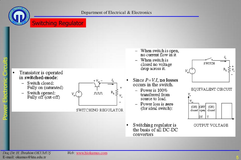
5 Switching Regulator 5
6 Buck (step-down) converter 6
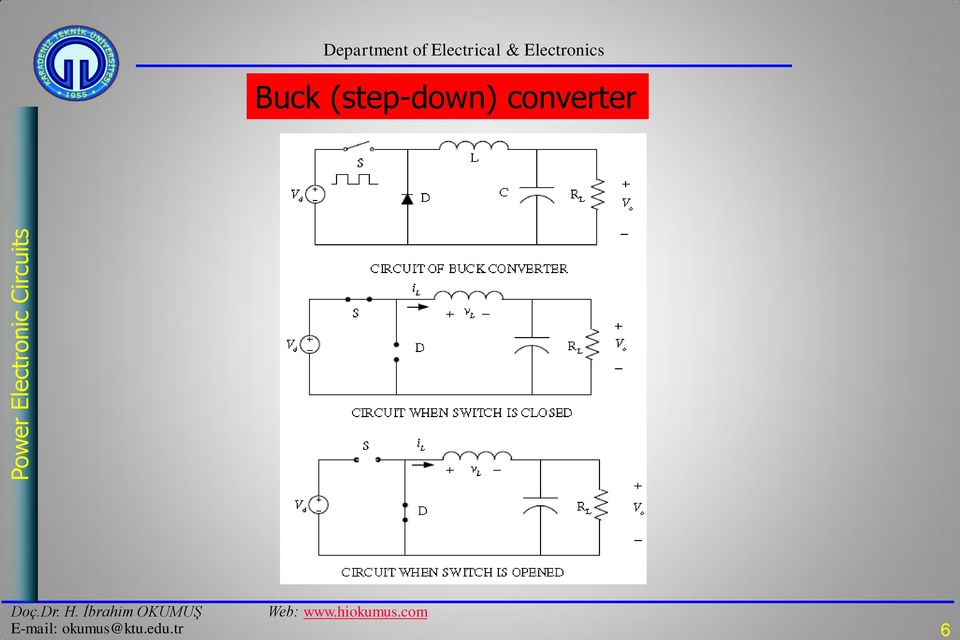
7 Switch is turned on (closed) 7

8 Switch turned off (opened) 8
")
9 Analysis 9

10 Steady-state operation 10

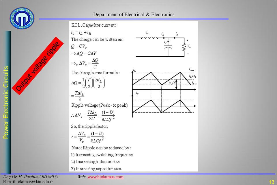
11 Average, Maximum and Minimum Inductor Current 11

12 Continuous Current Mode (CCM) 12

13 13
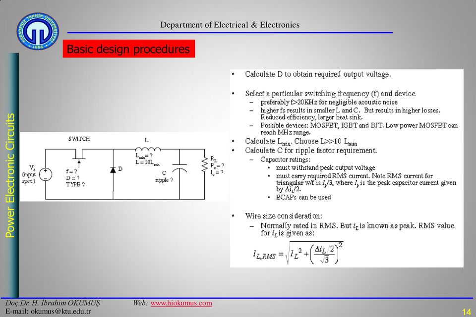
14 Basic design procedures 14
15 Examples A buck converter is supplied from a 50V battery source. Given L=400uH, C=100uF, R=20 Ohm, f=20khz and D=0.4. Calculate: (a) output voltage (b) maximum and minimum inductor current, (c) output voltage ripple. A buck converter has an input voltage of 50V and output of 25V. The switching frequency is 10KHz. The power output is 125W. (a) Determine the duty cycle, (b) value of L to limit the peak inductor current to 6.25A, (c) value of capacitance to limit the output voltage ripple factor to 0.5%. Design a buck converter such that the output voltage is 28V when the input is 48V. The load is 8Ohm. Design the converter such that it will be in continuous current mode. The output voltage ripple must not be more than 0.5%. Specify the frequency and the values of each component. Suggest the power switch also. 15

16 Boost (step-up) converter 16

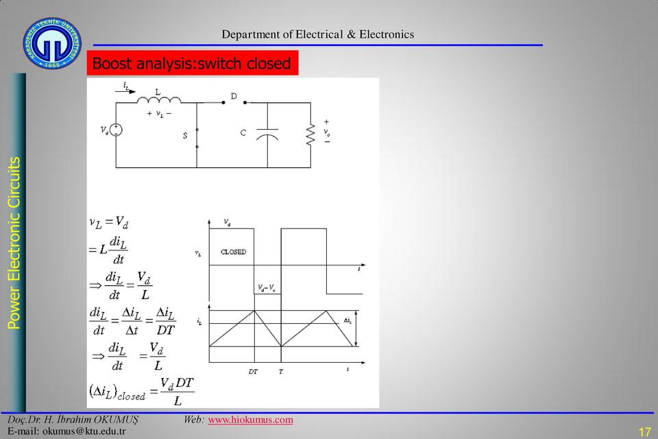
17 Boost analysis:switch closed 17
18 18
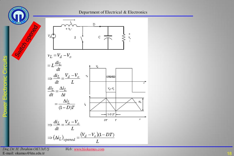
19 Boost converter produces output voltage that is greater or equal to the input voltage. Alternative explanation: when switch is closed, diode is reversed. Thus output is isolated. The input supplies energy to inductor. When switch is opened, the output stage receives energy from the input as well as from the inductor. Hence output is large. Output voltage is maintained constant by virtue of large C. 19

20 Average, Maximum, Minimum Inductor Current 20

21 21
22 Examples The boost converter has the following parameters: Vd=20V, D=0.6, R=12.5ohm, L=65uH, C=200uF, fs=40khz. Determine (a) output voltage, (b) average, maximum and minimum inductor current, (c) output voltage ripple. Design a boost converter to provide an output voltage of 36V from a 24V source. The load is 50W. The voltage ripple factor must be less than 0.5%. Specify the duty cycle ratio, switching frequency, inductor and capacitor size, and power device. 22
23 Buck-Boost converter 23
24 24
25 25
26 Average inductor current 26
27 27
28 Converters in CCM: Summary 28
29 Control of DC-DC converter: pulse width modulation (PWM) 29
30 Isolated DC-DC Converter Isolated DC-DC requires isolation transformer Two types: Linear and Switched-mode Advantages of switched mode over linear power supply -Efficient (70-95%) -Weight and size reduction Disadvantages -Complex design -EMI problems However above certain ratings, SMPS is the only feasible choice Types of SMPS -Flyback -forward -Push-pull -Bridge (half and full) 30
31 Linear and SMPS block diagram 31
32 High frequency transformer 32
33 Flyback Converter 33
34 Operation: switch closed 34
35 Switch opened 35
36 36
37 37
38 38
39 39
40 Full-bridge converter 40
41 Full bridge: basic operation 41
Power supplies. EE328 Power Electronics Assoc. Prof. Dr. Mutlu BOZTEPE Ege University, Dept. of E&E
 Power supplies EE328 Power Electronics Assoc. Prof. Dr. Mutlu BOZTEPE Ege University, Dept. of E&E EE328 POWER ELECTRONICS Outline of lecture Introduction to power supplies Modelling a power transformer
DC-DC Converter Basics
 Page 1 of 16 Free Downloads / Design Tips / Java Calculators / App. Notes / Tutorials / Newsletter / Discussion / Components Database / Library / Power Links / Software / Technical Articles / On-Line Textbook
Introduction to Power Supplies
 Introduction to Power Supplies INTRODUCTION Virtually every piece of electronic equipment e g computers and their peripherals calculators TV and hi-fi equipment and instruments is powered from a DC power
Design of Four Input Buck-Boost DC-DC Converter for Renewable Energy Application
 Design of Four Input Buck-Boost DC-DC Converter for Renewable Energy Application A.Thiyagarajan Assistant Professor, Department of Electrical and Electronics Engineering Karpagam Institute of Technology
The Flyback Converter
 The Flyback Converter Lecture notes ECEN4517! Derivation of the flyback converter: a transformer-isolated version of the buck-boost converter! Typical waveforms, and derivation of M(D) = V/! Flyback transformer
Chapter 6: Converter circuits
 Chapter 6. Converter Circuits 6.. Circuit manipulations 6.2. A short list of converters 6.3. Transformer isolation 6.4. Converter evaluation and design 6.5. Summary of key points Where do the boost, buck-boost,
TOPOLOGIES FOR SWITCHED MODE POWER SUPPLIES
 TOPOLOGIES FOR SWITCHED MODE POWER SUPPLIES by L. Wuidart I INTRODUCTION This paper presents an overview of the most important DC-DC converter topologies. The main object is to guide the designer in selecting
AC/DC Power Supply Reference Design. Advanced SMPS Applications using the dspic DSC SMPS Family
 AC/DC Power Supply Reference Design Advanced SMPS Applications using the dspic DSC SMPS Family dspic30f SMPS Family Excellent for Digital Power Conversion Internal hi-res PWM Internal high speed ADC Internal
DC/DC Converter Fundamentals
 Leistungselektronik Grundlagen und Standardanwendungen SS 2012 DC/DC Converter Fundamentals Prof. Hans-Georg Herzog Elektrische Energiewandlungstechnik Outline 1. Overview on DC/DC Converter 2. One-Quadrant
Fundamentals of Power Electronics. Robert W. Erickson University of Colorado, Boulder
 Robert W. Erickson University of Colorado, Boulder 1 1.1. Introduction to power processing 1.2. Some applications of power electronics 1.3. Elements of power electronics Summary of the course 2 1.1 Introduction
Parametric variation analysis of CUK converter for constant voltage applications
 ISSN (Print) : 232 3765 (An ISO 3297: 27 Certified Organization) Vol. 3, Issue 2, February 214 Parametric variation analysis of CUK converter for constant voltage applications Rheesabh Dwivedi 1, Vinay
Design and Construction of Variable DC Source for Laboratory Using Solar Energy
 International Journal of Electronics and Computer Science Engineering 228 Available Online at www.ijecse.org ISSN- 2277-1956 Design and Construction of Variable DC Source for Laboratory Using Solar Energy
Solar Energy Conversion using MIAC. by Tharowat Mohamed Ali, May 2011
 Solar Energy Conversion using MIAC by Tharowat Mohamed Ali, May 2011 Abstract This work introduces an approach to the design of a boost converter for a photovoltaic (PV) system using the MIAC. The converter
Development of High Frequency Link Direct DC to AC Converters for Solid Oxide Fuel Cells (SOFC)
") Development of High Frequency Link Direct DC to AC Converters for Solid Oxide Fuel Cells (SOFC) Dr. Prasad Enjeti Power Electronics Laboratory Department of Electrical Engineering College Station, TX -
Development of High Frequency Link Direct DC to AC Converters for Solid Oxide Fuel Cells (SOFC) Dr. Prasad Enjeti Power Electronics Laboratory Department of Electrical Engineering College Station, TX -
Transformerless UPS systems and the 9900 By: John Steele, EIT Engineering Manager
 Transformerless UPS systems and the 9900 By: John Steele, EIT Engineering Manager Introduction There is a growing trend in the UPS industry to create a highly efficient, more lightweight and smaller UPS
The full wave rectifier consists of two diodes and a resister as shown in Figure
 The Full-Wave Rectifier The full wave rectifier consists of two diodes and a resister as shown in Figure The transformer has a centre-tapped secondary winding. This secondary winding has a lead attached
Power Supplies. 1.0 Power Supply Basics. www.learnabout-electronics.org. Module
 Module 1 www.learnabout-electronics.org Power Supplies 1.0 Power Supply Basics What you ll learn in Module 1 Section 1.0 Power Supply Basics. Basic functions of a power supply. Safety aspects of working
Design and implementation of a modified DC- DC converter suitable for renewable energy application
 Le 3 ème Séminaire International sur les Nouvelles et Design and implementation of a modified DC- DC converter suitable for renewable energy application Tareq ALNEJAILI and Said DRID senior member IEEE
Power supply output voltages are dropping with each
 DESIGNER S SERIES Second-Stage LC Filter Design First Inductor by Dr. Ray Ridley First Capacitor Power supply output voltages are dropping with each new generation of Integrated Circuits (ICs). Anticipated
Design of an Auxiliary Power Distribution Network for an Electric Vehicle
 Design of an Auxiliary Power Distribution Network for an Electric Vehicle William Chen, Simon Round and Richard Duke Department of Electrical & Computer Engineering University of Canterbury, Christchurch,
Welcome to this presentation on Switch Mode Drivers, part of OSRAM Opto Semiconductors LED Fundamentals series. In this presentation we will look at:
 Welcome to this presentation on Switch Mode Drivers, part of OSRAM Opto Semiconductors LED Fundamentals series. In this presentation we will look at: How switch mode drivers work, switch mode driver topologies,
98% Efficient Single-Stage AC/DC Converter Topologies
 16 POWER CONVERTERS www.teslaco.com 98% Efficient Single-Stage AC/DC Converter Topologies A new Hybrid Switching Method is introduced in this article which for the first time makes possible AC/DC power
DC/DC BUCK Converter for Renewable Energy Applications Mr.C..Rajeshkumar M.E Power Electronic and Drives,
 DC/DC BUCK Converter for Renewable Energy Applications Mr.C..Rajeshkumar M.E Power Electronic and Drives, Mr.C.Anandaraj Assistant Professor -EEE Thiruvalluvar college of Engineering And technology, Ponnur
ULRASONIC GENERATOR POWER CIRCUITRY. Will it fit on PC board
 ULRASONIC GENERATOR POWER CIRCUITRY Will it fit on PC board MAJOR COMPONENTS HIGH POWER FACTOR RECTIFIER RECTIFIES POWER LINE RAIL SUPPLY SETS VOLTAGE AMPLITUDE INVERTER INVERTS RAIL VOLTAGE FILTER FILTERS
Application Report SLVA057
 Application Report March 1999 Mixed Signal Products SLVA057 IMPORTANT NOTICE Texas Instruments and its subsidiaries (TI) reserve the right to make changes to their products or to discontinue any product
7-41 POWER FACTOR CORRECTION
 POWER FTOR CORRECTION INTRODUCTION Modern electronic equipment can create noise that will cause problems with other equipment on the same supply system. To reduce system disturbances it is therefore essential
Relationship between large subject matter areas
 H02M APPARATUS FOR CONVERSION BETWEEN AC AND AC, BETWEEN AC AND DC, OR BETWEEN DC AND DC, AND FOR USE WITH MAINS OR SIMILAR POWER SUPPLY SYSTEMS; CONVERSION OF DC OR AC INPUT POWER INTO SURGE OUTPUT POWER;
Single-Stage High Power Factor Flyback for LED Lighting
 Application Note Stockton Wu AN012 May 2014 Single-Stage High Power Factor Flyback for LED Lighting Abstract The application note illustrates how the single-stage high power factor flyback converter uses
Understanding SMD Power Inductors. Application Note. July 2011
 Understanding SMD Power Inductors July 2011 Application Note Power inductors play an important role in voltage conversion applications by yielding lower core losses. They are also used to store energy,
International Journal of Science and Research (IJSR) ISSN (Online): 2319-7064 Index Copernicus Value (2013): 6.14 Impact Factor (2014): 5.
 ISSN (Online): 2319-7064 Index Copernicus Value (2013): 6.14 Impact Factor (2014): 5.") The Derivative of a Switched Coupled Inductor DC DC Step-Up Converter by Using a Voltage Lift Network with Closed Loop Control for Micro Source Applications Sangeetha K 1, Akhil A. Balakrishnan 2 1 PG
The Derivative of a Switched Coupled Inductor DC DC Step-Up Converter by Using a Voltage Lift Network with Closed Loop Control for Micro Source Applications Sangeetha K 1, Akhil A. Balakrishnan 2 1 PG
Bi-directional power converters for smart grids
 Bi-directional power converters for smart grids Isolated bidirectional DC-DC converter Welday Gebremedihn Gerekial Master of Science in Electric Power Engineering Submission date: June 214 Supervisor:
Boundary between CCM and DCM in DC/DC PWM Converters
 Boundary between CCM and DCM in DC/DC PWM Converters ELENA NICULESCU and E. P. IANCU Dept. of Electronics and Instrumentation, and Automation University of Craiova ROMANIA Abstract: - It is presented a
National Semiconductor Power Products - Seminar 3 (LED Lighting)
") National Semiconductor Power Products - Seminar 3 (LED Lighting) Dr. Iain Mosely Converter Technology Ltd. Slide 1 Overview Background on LEDs Power Electronics for Driving LEDs LED Driver Specific Solutions
National Semiconductor Power Products - Seminar 3 (LED Lighting) Dr. Iain Mosely Converter Technology Ltd. Slide 1 Overview Background on LEDs Power Electronics for Driving LEDs LED Driver Specific Solutions
Switched Mode Power Supplies
 CHAPTER 2 Switched Mode Power Supplies 2.1 Using Power Semiconductors in Switched Mode Topologies (including transistor selection guides) 2.2 Output Rectification 2.3 Design Examples 2.4 Magnetics Design
Powering Integrated Circuits (ICs), and managing ripple voltage as it relates
, and managing ripple voltage as it relates") Ripple Voltage & ESR Powering Integrated Circuits (ICs), and managing ripple voltage as it relates to ESR of capacitors Low voltage ICs require supply voltage (Vcc) to have reduced levels of ripple voltage
Ripple Voltage & ESR Powering Integrated Circuits (ICs), and managing ripple voltage as it relates to ESR of capacitors Low voltage ICs require supply voltage (Vcc) to have reduced levels of ripple voltage
DC Voltage Regulation by Buck Converter Applicable for Stand Alone Micro Hydro Power Generation
 International Journal of Electronic and Electrical Engineering. ISSN 0974-2174, Volume 7, Number 1 (2014), pp. 37-42 International Research Publication House http://www.irphouse.com DC Voltage Regulation
AN2389 Application note
 Application note An MCU-based low cost non-inverting buck-boost converter for battery chargers Introduction As the demand for rechargeable batteries increases, so does the demand for battery chargers.
Hybrid Power System with A Two-Input Power Converter
 Hybrid Power System with A Two-Input Power Converter Y. L. Juan and H. Y. Yang Department of Electrical Engineering National Changhua University of Education Jin-De Campus, Address: No.1, Jin-De Road,
Design and Simulation of Soft Switched Converter Fed DC Servo Drive
 International Journal of Soft Computing and Engineering (IJSCE) ISSN: 2231-237, Volume-1, Issue-5, November 211 Design and Simulation of Soft Switched Converter Fed DC Servo Drive Bal Mukund Sharma, A.
Chapter 1 dc-dc and regulation theory. Chapter 2 Small-signal theory
 Switch-Mode Power Supplies SPICE Simulations and Practical Designs OrCAD/PSpice Simulation Libraries and Design Templates Christophe Basso 2007 Revision 0.3 May 2007 The present Word file describes the
Diode Applications. As we have already seen the diode can act as a switch Forward biased or reverse biased - On or Off.
 Diode Applications Diode Switching As we have already seen the diode can act as a switch Forward biased or reverse biased - On or Off. Voltage Rectifier A voltage rectifier is a circuit that converts an
The leakage inductance of the power transformer
 Nondissipative lamping Benefits - onverters Even if small, a transformer s leakage inductance reduces the efficiency of some isolated dc-dc converter topologies However, the technique of lossless voltage
EMI and t Layout Fundamentals for Switched-Mode Circuits
 v sg (t) (t) DT s V pp = n - 1 2 V pp V g n V T s t EE core insulation primary return secondary return Supplementary notes on EMI and t Layout Fundamentals for Switched-Mode Circuits secondary primary
2.996/6.971 Biomedical Devices Design Laboratory Lecture 4: Power Supplies
 2.996/6.971 Biomedical Devices Design Laboratory Lecture 4: Power Supplies Instructor: Dr. Hong Ma Sept. 19, 2007 Key Problem Ideal voltage sources do not exist! Voltage regulators use feedback to reduce
Design A High Performance Buck or Boost Converter With Si9165
 Design A High Performance Buck or Boost Converter With Si9165 AN723 AN723 by Kin Shum INTRODUCTION The Si9165 is a controller IC designed for dc-to-dc conversion applications with 2.7- to 6- input voltage.
HIGH FREQUENCY TRANSFORMER WITH TRANSFORMER SWITCHOVER
 OPTIMUM EFFICIENCY AND FLEXIBLE USE HIGH FREQUENCY TRANSFORMER WITH TRANSFORMER SWITCHOVER One of the many requirements of the modern inverter is a broad, coordinated input and MPP voltage range with a
Properties of electrical signals
 DC Voltage Component (Average voltage) Properties of electrical signals v(t) = V DC + v ac (t) V DC is the voltage value displayed on a DC voltmeter Triangular waveform DC component Half-wave rectifier
Chapter 20 Quasi-Resonant Converters
 Chapter 0 Quasi-Resonant Converters Introduction 0.1 The zero-current-switching quasi-resonant switch cell 0.1.1 Waveforms of the half-wave ZCS quasi-resonant switch cell 0.1. The average terminal waveforms
47000 SERIES - ELECTRONIC TRANSFORMERS
 7000 SERIES - ELECTRONIC TRANSFORMERS MYRRA encapsulated electronic transformers are Switched Mode Power Supplies based on Flyback topology. They constitute an interesting alternative to the traditional
STUDY OF CELLPHONE CHARGERS
 STUDY OF CELLPHONE CHARGERS Author : Suraj Hebbar Systems Lab, CeNSE,IISc Banglore ABSTRACT This report shows charging nature of different cellphone chargers with different cellphones. Here we took into
Three-port DC-DC Converters to Interface Renewable Energy Sources with Bi-directional Load and Energy Storage Ports
 Three-port DC-DC Converters to Interface Renewable Energy Sources with Bi-directional Load and Energy Storage Ports A DISSERTATION SUBMITTED TO THE FACULTY OF THE GRADUATE SCHOOL OF THE UNIVERSITY OF MINNESOTA
Which is the best PFC stage for a 1kW application?
 Which is the best PFC stage for a 1kW application? Comparison of different PFC stage topologies under an identical design philosophy Ulf Schwalbe/ Marko Scherf ISLE Steuerungstechnik und Leistungselektronik
ANADOLU UNIVERSITY DEPARTMENT OF ELECTRICAL AND ELECTRONICS ENGINEERING
 ANADOLU UNIVERSITY DEPARTMENT OF ELECTRICAL AND ELECTRONICS ENGINEERING EEM 102 INTRODUCTION TO ELECTRICAL ENGINEERING EXPERIMENT 9: DIODES AND DC POWER SUPPLY OBJECTIVE: To observe how a diode functions
Evaluating AC Current Sensor Options for Power Delivery Systems
 Evaluating AC Current Sensor Options for Power Delivery Systems State-of-the-art isolated ac current sensors based on CMOS technology can increase efficiency, performance and reliability compared to legacy
Noise Free 90+ for LCD TV AC Adapter Desk Top. 96% x 96% = 92.16% Champion Microelectronic. 96+ Interleaved CRM PFC CM6565 PFC & PFC PWM PWM
 Soft Soft Switching Switching PFC PFC & & Soft Soft Switching Switching PWM PWM 96% x 96% = 92.16% Noise Free 90+ for LCD TV AC Adapter Desk Top 1 96% x 96% = 92.16% 96+ LLC/SRC + SR CM6900/1 92% x 96%
Chapter 11 Current Programmed Control
 Chapter 11 Current Programmed Control Buck converter v g i s Q 1 D 1 L i L C v R The peak transistor current replaces the duty cycle as the converter control input. Measure switch current R f i s Clock
Bridgeless PFC Implementation Using One Cycle Control Technique
 Bridgeless PFC Implementation Using One Cycle Control Technique Bing Lu Center for Power Electronics Systems Virginia Polytechnic Institute and State University 674 Whittemore Hall Blacksburg, VA 24061
Planar versus conventional transformer
 Planar versus conventional transformer Majid Dadafshar, Principal Engineer Gerard Healy, Field Application Engineer Pulse, a Technitrol Company Power Division Usually the first step on any power supply
Chapter 17 The Ideal Rectifier
 Chapter 17 The Ideal Rectifier 17.1 Properties of the ideal rectifier 17.2 Realization of a near-ideal rectifier 17.3 Single-phase converter systems employing ideal rectifiers 17.4 RMS values of rectifier
Current Ripple Factor of a Buck Converter
 Application Note Edwin Wang AN1 April 14 Current Ripple Factor of a Buck Converter Abstract Inductor and capacitor forms a low-pass filter in a buck converter. The corner frequency the C filter is always
Switch Mode Power Supply Topologies
 Switch Mode Power Supply Topologies The Buck Converter 2008 Microchip Technology Incorporated. All Rights Reserved. WebSeminar Title Slide 1 Welcome to this Web seminar on Switch Mode Power Supply Topologies.
Bi-directional Power System for Laptop Computers
 Bi-directional Power System for Laptop Computers Terry L. Cleveland Staff Applications Engineer Microchip Technology Inc. [email protected] Abstract- Today the typical laptop computer uses
0.9V Boost Driver PR4403 for White LEDs in Solar Lamps
 0.9 Boost Driver for White LEDs in Solar Lamps The is a single cell step-up converter for white LEDs operating from a single rechargeable cell of 1.2 supply voltage down to less than 0.9. An adjustable
A NEW TWO SWITCH TOPOLOGY BUCK BOOST CONVERTOR IN UNIVERSAL INPUT PFC APPLICATION
 A NEW TWO SWITCH TOPOLOGY BUCK BOOST CONVERTOR IN UNIVERSAL INPUT PFC APPLICATION Ranjana Khandare 1, Deepak Rathod 1 and *Asutosh K Pandey 2 1 Department of Electrical Engineering 2 Department of Engineering
Modeling and Simulation of a Novel Switched Reluctance Motor Drive System with Power Factor Improvement
 American Journal of Applied Sciences 3 (1): 1649-1654, 2006 ISSN 1546-9239 2006 Science Publications Modeling and Simulation of a Novel Switched Reluctance Motor Drive System with Power Factor Improvement
Common Power Supply Topologies
 Technical Article Common Power Supply Topologies CONTENTS Introduction Buck Boost Flyback The three basic topologies used in switching power supplies are buck, also known as forward, boost and buck-boost,
T.FRANCIS, D.NARASIMHARAO
 Applications (IJERA) ISSN: 48-96 wwwijeracom ol, Issue 3, May-Jun 0, pp40-46 A Soft-Switching DC/DC Converter With High oltage Gain for Renewable Energy Application TFRANCIS M-Tech Scholar, Power electronics
Chapter 4. LLC Resonant Converter
 Chapter 4 LLC Resonant Converter 4.1 Introduction In previous chapters, the trends and technical challenges for front end DC/DC converter were discussed. High power density, high efficiency and high power
Designers Series XII. Switching Power Magazine. Copyright 2005
 Designers Series XII n this issue, and previous issues of SPM, we cover the latest technologies in exotic high-density power. Most power supplies in the commercial world, however, are built with the bread-and-butter
AND8147/D. An Innovative Approach to Achieving Single Stage PFC and Step-Down Conversion for Distributive Systems APPLICATION NOTE
 An Innovative Approach to Achieving Single Stage PFC and Step-Down Conversion for Distributive Systems APPLICATION NOTE INTRODUCTION In most modern PFC circuits, to lower the input current harmonics and
DC To DC Converter in Maximum Power Point Tracker
 DC To DC Converter in Maximum Power Point Tracker V.C. Kotak 1, Preti Tyagi 2 Associate Professor, Dept of Electronics Engineering, Shah &Anchor Kutchhi Engineering College, Mumbai, India 1 Research Scholar
Power Electronics. Alberto Tibaldi. July 13, 2010
 Power Electronics Alberto Tibaldi July 13, 2010 Contents 1 Switch-mode power supplies 9 1.1 Introduction............................ 9 1.1.1 Introduction to basic topologies of switching-mode converters...........................
Solar Mobile charging Solutions
 Solar Mobile charging Solutions Solar power is one of the widely available energy sources. It has been in focus worldwide and solar installations of capacities in megawatts order are reality today. The
Preliminary Datasheet
 Features Macroblock Preliminary Datasheet 1.2A Constant Output Current 93% Efficiency @ input voltage 13V, 350mA, 9~36V Input Voltage Range Hysteretic PFM Improves Efficiency at Light Loads Settable Output
When the Power Fails: Designing for a Smart Meter s Last Gasp
 When the Power Fails: Designing for a Smart Meter s Last Gasp Daniel Pruessner 1/10/2012 5:25 PM EST Overview Smart meter designers have an unusual predicament: The meter is powered from the same bus that
Design of Solar Power Optimizer And Eliminating Leakage Current In Multi-Level Inverter For PV Systems
 Design of Solar Power Optimizer And Eliminating Leakage Current In Multi-Level Inverter For PV Systems A. Asaph 1, Dr. P. Selvan 2 1 PG Scholar, 2 Head of the Department, Erode Sengunthar Engineering College,
High Frequency True PWM Dimming White LED Driver MP3304 and MP3305
 The Future of Analog IC Technology AN021 High Frequency True PWM Dimming White LED Driver MP3304 and MP3305 High Frequency True PWM Dimming White LED Driver MP3304 and MP3305 Prepared by Zhijun Ye and
AN ULTRA-CHEAP GRID CONNECTED INVERTER FOR SMALL SCALE GRID CONNECTION
 AN ULTRA-CHEAP GRID CONNECTED INVERTER FOR SMALL SCALE GRID CONNECTION Pramod Ghimire 1, Dr. Alan R. Wood 2 1 ME Candidate Email: [email protected] 2 Senior Lecturer: Canterbury University
LM2576R. 3.0A, 52kHz, Step-Down Switching Regulator FEATURES. Applications DESCRIPTION TO-220 PKG TO-220V PKG TO-263 PKG ORDERING INFORMATION
 LM2576 FEATURES 3.3, 5.0, 12, 15, and Adjustable Output ersions Adjustable ersion Output oltage Range, 1.23 to 37 +/- 4% AG10Maximum Over Line and Load Conditions Guaranteed 3.0A Output Current Wide Input
UNDERSTANDING POWER FACTOR AND INPUT CURRENT HARMONICS IN SWITCHED MODE POWER SUPPLIES
 UNDERSTANDING POWER FACTOR AND INPUT CURRENT HARMONICS IN SWITCHED MODE POWER SUPPLIES WHITE PAPER: TW0062 36 Newburgh Road Hackettstown, NJ 07840 Feb 2009 Alan Gobbi About the Author Alan Gobbi Alan Gobbi
Design a Phase Interleaving PFC Buck Boost Converter to Improve the Power Factor
 International Journal of Innovation and Scientific Research ISSN 2351-8014 Vol. 11 No. 2 Nov. 2014, pp. 445-449 2014 Innovative Space of Scientific Research Journals http://www.ijisr.issr-journals.org/
Series AMLDL-Z Up to 1000mA LED Driver
 FEATURES: Click on Series name for product info on aimtec.com Series Up to ma LED Driver Models Single output Model Input Voltage (V) Step Down DC/DC LED driver Operating Temperature range 4ºC to 85ºC
Chapter 2 Application Requirements
 Chapter 2 Application Requirements The material presented in this script covers low voltage applications extending from battery operated portable electronics, through POL-converters (Point of Load), internet
Application Notes. Magnetics. Determining L min for Buck/Boost Converters
 Application Notes Magnetics etermining min for Buck/Boost onverters Fundamental oncepts 172 alculating Minimum nductance Buck Type onverters 174 Boost Type onverters 177 Buck-Boost onverters 180-171 APPATON
High Performance ZVS Buck Regulator Removes Barriers To Increased Power Throughput In Wide Input Range Point-Of-Load Applications
 White paper High Performance ZVS Buck Regulator Removes Barriers To Increased Power Throughput In Wide Input Range Point-Of-Load Applications Written by: C. R. Swartz Principal Engineer, Picor Semiconductor
Novel Loaded-Resonant Converter & Application of DC-to-DC Energy Conversions systems
 International Refereed Journal of Engineering and Science (IRJES) ISSN (Online) 2319-183X, (Print) 2319-1821 Volume 2, Issue 11 (November 2013), PP.50-57 Novel Loaded-Resonant Converter & Application of
SWITCHING REGULATORS
 SWITCHING REGULATORS Introduction The switching regulator is increasing in popularity because it offers the advantages of higher power conversion efficiency and increased design flexibility (multiple output
O WA-120U series IP67. 120W Single Output Switching Power Supply. Features. Aplications
 Features UniversalACinput/Fulrange Built-inactivePFCfunction Higheficiencyupto91% Protections:Shortcircuit/Overcurent/ Overvoltage/Overtemperature Fanlesdesign,colingbyfreairconvection Colingbyfreairconvection
HIGH FREQUENCY POWER CONVERTERS. Authors: Rudy Severns, Springtime Enterprises Hal Wittlinger, Intersil Semiconductor
 No. AN9208 April 994 Application Note HIGH FREQUENCY POWER CONVERTERS Authors: Rudy Severns, Springtime Enterprises Hal Wittlinger, Intersil Semiconductor Introduction Computers and telecom equipment are
1ED Compact A new high performance, cost efficient, high voltage gate driver IC family
 1ED Compact A new high performance, cost efficient, high voltage gate driver IC family Heiko Rettinger, Infineon Technologies AG, Am Campeon 1-12, 85579 Neubiberg, Germany, [email protected]
A HIGH GAIN HYBRID DC-DC BOOST-FORWARD CONVERTER FOR SOLAR PANEL APPLICATIONS. Nicklas Jack Havens
 A HIGH GAIN HYBRID DC-DC BOOST-FORWARD CONVERTER FOR SOLAR PANEL APPLICATIONS by Nicklas Jack Havens A thesis submitted in partial fulfillment of the requirements for the degree of Master of Science in
Hello and welcome to this training module for the STM32L4 Liquid Crystal Display (LCD) controller. This controller can be used in a wide range of
 controller. This controller can be used in a wide range of") Hello and welcome to this training module for the STM32L4 Liquid Crystal Display (LCD) controller. This controller can be used in a wide range of applications such as home appliances, medical, automotive,
Hello and welcome to this training module for the STM32L4 Liquid Crystal Display (LCD) controller. This controller can be used in a wide range of applications such as home appliances, medical, automotive,
Interleaved Boost DC-DC Converter Using Delta-Sigma Modulation Suitable for Renewable Energy Applications
 Interleaved Boost DC-DC Converter Using Delta-Sigma Modulation Suitable for Renewable Energy Applications Farag S. Alargt, Ahmed S. Ashur, Mohamed A. Shrud, and Ahmad H. Kharaz significantly [3]. The conversion
Chapter 19 Resonant Conversion
 Chapter 9 Resonant Conversion Introduction 9. Sinusoidal analysis of resonant converters 9. Examples Series resonant converter Parallel resonant converter 9.3 Exact characteristics of the series and parallel
Application Note, Rev.1.0, September 2008 TLE8366. Application Information. Automotive Power
 Application Note, Rev.1.0, September 2008 TLE8366 Automotive Power Table of Contents 1 Abstract...3 2 Introduction...3 3 Dimensioning the Output and Input Filter...4 3.1 Theory...4 3.2 Output Filter Capacitor(s)
UNDERSTANDING AND CONTROLLING COMMON-MODE EMISSIONS IN HIGH-POWER ELECTRONICS
 Page 1 UNDERSTANDING AND CONTROLLING COMMON-MODE EMISSIONS IN HIGH-POWER ELECTRONICS By Henry Ott Consultants Livingston, NJ 07039 (973) 992-1793 www.hottconsultants.com [email protected] Page 2 THE BASIC
Comparison of an Efficient Buck Converter Configuration for the DC Power Distribution Of Future Green Data Centers
 Comparison of an Efficient Buck Converter Configuration for the DC Power Distribution Of Future Green Data Centers Sindhu Shetty 1, I. V. Prasanna 2, S. K. Panda 3 UG student, Dept. of EEE, National Institute
5W LED Lump Module Design with FT831B
 5W LED Lump Module Design with FT831B 2009 Fremont Micro Devices ERP831BA1 - Page1 Index 1 INTRODUCTION... 3 2 MODULE SPECIFICATION... 3 2.1 Input Characteristics... 3 2.2 Output Characteristics... 3 2.3
High Intensify Interleaved Converter for Renewable Energy Resources
 High Intensify Interleaved Converter for Renewable Energy Resources K. Muthiah 1, S.Manivel 2, Gowthaman.N 3 1 PG Scholar, Jay Shriram Group of Institutions,Tirupur 2 Assistant Professor, Jay Shriram Group
Power Electronics Lab
 Power Electronics Lab By: Alex M. Bermel : April 20, 2011 Table of Contents Title page 1 Table of Contents 2 Project Scope 4 Problem Statement 4 Health and Safety 5 Customer Needs 6 Economic Analysis 6