Transmission Protection Overview
|
|
|
- Gillian Brown
- 9 years ago
- Views:
Transcription
1 Transmission Protection Overview 2012 Hands-On Relay School Brian Smyth Schweitzer Engineering Laboratories Pullman, WA

2 Transmission Line Protection Objective General knowledge and familiarity with transmission protection schemes

3 Transmission Line Protection Topics Primary/backup protection Coordination Communication-based schemes Breaker failure protection Out-of-step relaying Synchronism checking

4 Primary Protection Function Trip for abnormal system conditions that may Endanger human life Damage system equipment Cause system instability

5 Protection Zones Primary protection first line of defense Backup protection operates when primary fails

6 How Can A Protection System Fail? Current or voltage signal supply Tripping voltage supply Power supply to the relay Protective relay Tripping circuit Circuit breaker

7 Two Types of Backup Remote backup Located at different station No common elements Local backup Located at same station Few common elements Separate relays Independent tripping supply and circuit Different current and voltage inputs

8 Remote vs Local Backup Speed Remote is slower Selectivity Remote disconnects larger part of the system Price Local requires additional equipment

9 Primary and Backup Coordination Best selectivity with minimum operating time Achieved through settings Pick up values Time delays

10 Coordination Types Considered Time-Overcurrent Time-Stepped Distance Communication-Aided Schemes

11 Time-Overcurrent Relays Definite-Time Overcurrent Operate in a settable time delay when the current exceeds the pickup value Instantaneous operation no intentional time delay Inverse-Time Overcurrent Operating curve defined by limiting the total fault energy (K d = I 2 t)

12 Time-Overcurrent Coordination Inverse-Time Overcurrent Pickup of relay A set low enough to see the fault shown and backup relay C Pickup should be above emergency load conditions (phase relays) Time delay of relay A should allow relay C to clear the fault first

13 Time-Overcurrent Coordination S - Selectivity time delay (aka CTI): Breaker operating time Overtravel (impulse) time (E/M relays) Safety margin 0.2s CTI 0.4s
 time (E/M relays) Safety")
14 Time-Overcurrent Coordination Looped Systems Directionality required for most relays a-b-c-d-e Relays at 5 and e can be nondirectional

15 Instantaneous Overcurrent Protection Inverse-Time O/C coordination may result in long time delays Instantaneous O/C relays set to trip for faults for ~80% of the line section Significantly reduced tripping times for many faults

16 Time-Stepped Distance Protection Coordination similar to that of inverse-time O/C Relay at A set to trip instantaneous for faults in its Zone 1 (reaching ~80% of the line section) Relay at A backs up relay at C after Zone 2 timer times out Faults at the end of the line also cleared in Zone 2 time

17 Communication-Based Protection Rationale Distance protection can clear faults instantaneously for 60% to 80% of the line length Protection speed may be critical to maintain system stability High-speed autoreclosing application

18 Communication-Based Protection Communication Mediums Power Line Carrier Microwave Fiber-Optics Private and Leased Pilot Channels

19 Communication-Based Protection Scheme Types Permissive Overreaching Transfer Trip (POTT) Permissive Underreaching Transfer Trip (PUTT) Directional Comparison Blocking (DCB) Directional Comparison Unblocking (DCUB) Direct Underreaching Transfer Trip (DUTT) Direct Transfer Trip (DTT)
 Direct Underreaching Transfer Trip (DUTT) Direct")
20 Permissive Overreaching TT Protective Zones
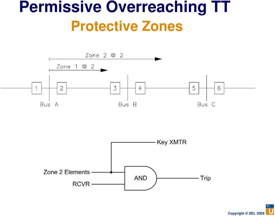
21 Permissive Overreaching TT Permissive signal must be detected from the remote end for the communicationaided trip Absence of communication channel disables the accelerated tripping
22 Permissive Overreaching TT Complications and Concerns Desensitization due to infeed Dependability issue failure to trip high speed Current reversal Occurs in parallel lines with sequential tripping Security issue coupled with long channel reset times may cause trip of the healthy parallel line
23 Current Reversal All Sources In Z2 at Breaker 1 picks up and sends permissive signal to Breaker 2 Z2 at Breakers 3 and 4 send permissive signals to each other Z1 at Breaker 4 trips instantaneously
24 Current Reversal System After Breaker 4 Opens Current reverses through the healthy line Z2 at Breaker 2 picks up If the permissive signal has not reset, Breaker 2 trips on POTT
25 Current Reversal Possible Solution Timer with instantaneous pickup and time delayed dropout, initiated on reverse Z3 Delay trip with POTT until the timer drops out
26 Permissive Underreaching TT Similar to POTT but permissive signal sent by underreaching Z1 elements At the receiving end, Z2 elements qualify the permissive signal No problems with current reversal since Z1 doesn t overreach
27 Directional Comparison Blocking Protective Zones Zone 2 elements cover the entire line Reverse Zone 3 elements must reach further than the opposite Zone 2 overreach
28 Directional Comparison Blocking Basic Logic In-section faults will not key transmitter and both ends trip high-speed Out-of-section fault will key the transmitter at the nearest end to block the trip at the opposite end
29 Directional Comparison Blocking Complications and Concerns Coordinating time at fault inception Z3 faster than Z2, but channel delay time reduces the margin Z2 must be slowed down External fault clearing Z3 and Z2 race to drop out, if Z3 drops out first Z2 overtrips Z3 operates faster and drops slower Channel reset time helps Slower transmitter key dropout time helps
30 Directional Comparison Blocking Complications and Concerns External fault clearing failure Local backup provided by time-delayed Z3 or external BF relay clears the near bus Remote backup provided by Z2 clears the line Stop preference over start
31 Directional Comparison Blocking Complications and Concerns Current reversal Reach Margin Z3 reaches farther back than remote Z2 by at least 50% of Z2 overreach
32 Directional Comparison Unblocking Essentially the same as POTT Requires FSK In-section fault may impede communication In case of channel loss, a 150 ms window is open when permissive signal is bypassed and Z2 allowed to trip high speed
33 Direct Underreaching TT Underreaching Z1 elements send direct transfer trip Noisy channel can cause false trip Very secure channel required
34 Pilotless Accelerated Trip Schemes Communication equipment not justifiable in lower voltage transmission applications In-section faults may be uniquely determined by system conditions Detecting these conditions is all that is needed for high speed tripping
35 Pilotless Accelerated Trip Schemes Faulted System with Breakers Closed After Breaker 2 opens the only current that can flow is the fault current
36 Pilotless Accelerated Trip Schemes Faulted System with Breaker 2 Open Tripping conditions: Three-phase load was present before the fault Three-phase current was lost Current above the threshold detected in at least one phase
37 Breaker Failure Relaying Minimize the damage when a breaker fails to clear a fault Trips all sources locally within the critical clearing time to maintain system stability
38 Breaker Failure Relaying Common Causes of Breaker Failure Main breaker poles failed to clear the fault due to inadequate insulating medium Open trip coil or trip coil circuit Loss of tripping dc Mechanical failure of the breaker trip mechanism
39 Breaker Failure Relaying Operating Philosophy Activated only when a trip signal is issued from protective relay If current is above threshold after a pre-set time period, breaker failure condition is declared
40 Breaker Failure Relaying Considerations Timer settings must take into account the clearing time of the slowest breaker and the reset time of the fault detector The effect of any opening resistors in the circuit breakers on the reset time of fault detector Substation bus configuration must be taken into account to trip minimum number of breakers In multi-breaker schemes, possible transfer trip to the remote end
41 Out-of-Step Detection and Blocking Causes of Out-of-Step Power swings result from faults, switching, or big changes in load or generation Magnitude of the swing depends on the system impedance change during such conditions Swings can be stable or unstable
42 Power Transfer Equation where:, sin δ P power transferred from the sending to the receiving end V V S R P= P = P = sending end voltage receiving end voltage δ angle by which V leads V S S R VV X total reactance between the sending and receiving end R S X R
43 Power Transfer Curves,
44 Electrical Quantities During Swing Apparent Impedance Trajectories
45 Electrical Quantities During Swing Apparent Impedance Trajectories Apparent impedance during power swings can enter into the reach of distance relays If the apparent impedance stays longer than the time delay in a given zone, that distance element will trip as for a fault To prevent such tripping, out-of-step blocking schemes are employed
46 Out-of-Step Blocking Distance Elements If the timer expires between the two zones, out-of-step condition is declared and selected distance elements are blocked
47 Synchronism Checking After clearing a fault, one end of the line will reclose to test the line If the test is good, the other end can be closed but only if voltages are close enough and there is a small phase angle difference If the conditions are not right, the system will undergo a mechanical and electrical shock with a possible unstable swing
48 Synchronism Checking Monitored Quantities Voltage magnitudes Phase angle difference Slip frequency
49 Synchronism Checking Synchronizer Window
50 Synchronism Checking Conditions Both voltage phasors are above 59V setting Phase angle difference is small The above conditions are maintained for a short time, ensuring that the slip frequency is small enough and measurements are valid
51 Synchronism Checking Relay Phasor difference setting 25DV = 59V sinθ Timer setting 2 θ 25T = 360 Δ f The measured phasor difference should be below the setting for the given time Different than a synchronizing relay
52 Questions?
INTRODUCTION TO SYSTEM PROTECTION. Hands-On Relay School 2012
 INTRODUCTION TO SYSTEM PROTECTION Hands-On Relay School 2012 CONGRATULATIONS On choosing the field of system protection. It is an exciting, challenging profession. System protection has changed considerably
Teleprotection Schemes and Equipment. James W. Ebrecht Young Power Equipment Scottsdale, AZ
 * Teleprotection Schemes and Equipment James W. Ebrecht Young Power Equipment Scottsdale, AZ Teleprotection Schemes And Equipment ~ ~ Relay Relay Teleprotection Communications channel Teleprotection Protection
Local Back-up Protection for an Electric Power System
 MULTILIN GER-3178 GE Power Management Local Back-up Protection for an Electric Power System LOCAL BACK UP PROTECTION FOR AN ELECTRIC POWER SYSTEM J. BERDY TABLE OF CONTENTS Transmission Line Back-Up Protection...............................................
TA Kahraman Yumak ELK412 - Distribution of Electrical Energy Lab. Notes v1.0 2013 Spring web.itu.edu.tr/yumakk. Distance Protection
 Distance Protection Announcement: You are not supposed to prepare a pre-report. But there will be an oral examination, so you are strongly advised to study this note regarding to the pre-study questions
Directional Comparison Blocking System Fundamentals
 Directional Comparison Blocking System Fundamentals Russell Patterson Patterson Power Engineers, LLC Elmo Price ABB Inc. Miriam Sanders Quanta Technology Introduction This paper discusses the fundamentals
Pilot-wire differential relay for lines with two or more terminals
 Pilot-wire differential relay for lines with two or more terminals Page 1 Issued: March 2003 Revision: A Data subject to change without notice Pilot-wire differential relay with RXHL 401 Features Phase
ECE 586b Course Project Report. Auto-Reclosing
 ECE 586b Course Project Report Auto-Reclosing Srichand Injeti May 5, 2008 Department Of Electrical and computer Engineering University Of Western Ontario, London Ontario Table of contents 1. Introduction...1
OVERCURRENT & EARTH FAULT RELAYS. To study the protection of equipment and system by relays in conjunction with switchgear.
 OVERCURRENT & EARTH FAULT RELAYS Objective: To study the protection of equipment and system by relays in conjunction with switchgear. Theory: The function of a relay is to detect abnormal conditions in
Application of Overreaching Distance Relays
 Outline 1. Introduction. Background Application of Overreaching Distance elays Why we are writing this document. A. Zone Descriptions B. Purpose of overreaching distance zones; step-distance and pilot
Assessment of power swing blocking functions of line protective relays for a near scenario of the Uruguayan system
 Assessment of power swing blocking functions of line protective relays for a near scenario of the Uruguayan system C. Sena, R. Franco, A. Giusto. Instituto de Ingeniería Eléctrica Facultad de Ingeniería
Transmission Line Protection Principles
 Transmission Line Protection Principles. Introduction Transmission lines are a vital part of the electrical distribution system, as they provide the path to transfer power between generation and load.
Relay-to-Relay Digital Logic Communication for Line Protection, Monitoring, and Control
 Relay-to-Relay Digital Logic Communication for Line Protection, Monitoring, and Control Kenneth C. Behrendt Schweitzer Engineering Laboratories, Inc. Revised edition released November 1998 Previously presented
Advanced Protection of Distribution Networks with Distributed Generators
 Date:- 8 10 March 2011 Venue: University of Manchester EES-UETP Course title Advanced Protection of Distribution Networks with Distributed Generators Peter Crossley Director of the Joule Centre School
Permissible ambient temperature Operation Storage, transport
 The Sitras PRO combined DC protective unit and controller is used in the power supply for DC railways in mass transit and main-line systems up 3,000 V DC. It protects DC switch gear and contact line systems
MiCOM P432 and P439. Distance Protection and Control Units. Protection Relays
 01 MiCOM P432 and P439 Distance Protection and Control Units The MiCOM P432 and P439 are cost effective one-box solutions for integrated numerical distance protection and control. P439 in case 40TE P432
Electric utilities may vary in their application of end-to-end testing
 An Application Case of End-to-End Relay Testing of Communication-Based Protection Schemes Using GPS-Synchronized Secondary Injection Feature by J. Ariza, Megger USA G. Ibarra, CFE, Mexico Electric utilities
EVALUATION OF ALTERNATIVE BACKUP PROTECTION SCHEMES ON A 66KV DISTRIBUTION NETWORK
 EVALUATION OF ALTERNATIVE BACKUP PROTECTION SCHEMES ON A 66KV DISTRIBUTION NETWORK F. Malone*, P.D. Doyle *ESB International, Ireland [email protected] ESB International, Ireland [email protected]
SIPROTEC Protection Technology
 SIPROTEC Protection Technology The Basis for Highest Availability of Supply Siemens AG 2012. Siemens All rights reserved. AG 2012 Infrastructure and Cities Objectives of this Brochure Objective The following
15LINE PROTECTION WITH PILOT RELAYS
 15LINE PROTECTION WITH PILOT RELAYS Pilot relaying is the best type for line protection. It is used whenever high-speed protection is required for all types of short circuits and for any fault location.
Power Quality Paper #3
 The Effect of Voltage Dips On Induction Motors by: M D McCulloch 1. INTRODUCTION Voltage depressions caused by faults on the system affect the performance of induction motors, in terms of the production
Special Considerations in Applying Power Line Carrier for Protective Relaying
 SPECIAL CONSIDERATIONS IN APPLYING POWER LINE CARRIER FOR PROTECTIVE RELAYING IEEE Power Systems Relaying Committee Special paper Relaying Communications Subcommittee, Working Group H9 Membership of the
Loss of ac Voltage Considerations For Line Protection
 Loss of ac Voltage Considerations For Line Protection A report prepared for the Line Protection Subcommittee Of the IEEE Power Engineering Society, Power System Relaying Committee Line Protection Subcommittee
100% Stator Ground Fault Detection Implementation at Hibbard Renewable Energy Center. 598 N. Buth Rd 3215 Arrowhead Rd
 100% Stator Ground Fault Detection Implementation at Hibbard Renewable Energy Center Introduction Roger Hedding Steven Schoenherr, P.E. ABB Inc. Minnesota Power 598 N. Buth Rd 3215 Arrowhead Rd Dousman,
Test & Data Management Software
 Test & Data Management Software TDMS protective relays energy meters transducers power quality CT-VT-PT transformers ground grid circuit breakers batteries surge arresters The Integrated Testing Solution
INTRODUCTION TO SYNCHRONIZING AUTOMATIC SYNCHRONIZING CONSIDERATIONS AND APPLICATIONS
 INTRODUCTION TO SYNCHRONIZING AUTOMATIC SYNCHRONIZING CONSIDERATIONS AND APPLICATIONS INTRODUCTION It is the intention of this presentation to provide an explanation of the automatic synchronizing process,
TDMS Test & Data Management Software
 Test & Data Management Software TDMS protective relays energy meters transducers power quality CT-VT-PT transformers ground grid circuit breakers batteries surge arresters The Integrated Testing Solution
SPECIAL TOPICS ON GROUND FAULT PROTECTION AND PROTECTION COORDINATION IN INDUSTRIAL AND COMMERCIAL POWER SYSTEMS
 SPECIAL TOPICS ON GROUND FAULT PROTECTION AND PROTECTION COORDINATION IN INDUSTRIAL AND COMMERCIAL POWER SYSTEMS Claudio S. Mardegan [email protected] www.engepower.com Phone: 55 3579-8777
2. A conductor of length 2m moves at 4m/s at 30 to a uniform magnetic field of 0.1T. Which one of the following gives the e.m.f. generated?
 Extra Questions - 2 1. A straight length of wire moves through a uniform magnetic field. The e.m.f. produced across the ends of the wire will be maximum if it moves: a) along the lines of magnetic flux
Numerical Differential Protection
 Numerical Differential Protection Principles and Applications Publicis Corporate Publishing 1 Introduction 8 1.1 Protection Principle 8 1.2 Numerical Differential Protection 9 2 Deflnitions 10 3 Mode of
The Application and Benefits of Multi-phase Auto-reclosing
 he Application and Benefits of Multi-phase Auto-reclosing etsuya Miyoshi*, Atsushi Kasai* Abstract - In this paper we explain the disadvantages in using single- and three-phase auto-reclosing on double
Challenges of Protection and Control System Verification on DP3 vessels with Focus on Ride Through Fault and Blackout
 Author s Name Name of the Paper Session DYNAMIC POSITIONING CONFERENCE October 15-16, 2013 POWER SESSION Challenges of Protection and Control System Verification on DP3 vessels with Focus on Ride Through
The following table shows approximate percentage wise the
 SHORT-CIRCUIT CALCULATION INTRODUCTION Designing an electrical system is easy and simple, if only the normal operation of the network is taken into consideration. However, abnormal conditions which are
Impact of Distributed Resources on Distribution Relay Protection
 Impact of Distributed Resources on Distribution Relay Protection A report to the Line Protection Subcommittee of the Power System Relay Committee of The IEEE Power Engineering Society prepared by working
SUBJECT: How to wire a motor starter Number: AN-MC-004 Date Issued: 2/08/2005 Revision: Original
 SUBJECT: How to wire a motor starter Number: AN-MC-004 Date Issued: 2/08/2005 Revision: Original A motor starter is a combination of devices to allow an induction motor to start, run and stop according
Distribution Operations with High-penetration of Beyond the Meter Intermittent Renewables. Bob Yinger Southern California Edison April 15, 2014
 1 Distribution Operations with High-penetration of Beyond the Meter Intermittent Renewables Bob Yinger Southern California Edison April 15, 2014 Southern California Edison SCE provides power to: Nearly
Everything you need for protection scheme testing
 Power System Simulator for Testing Protection Relays and Schemes Everything you need for protection scheme testing The is the only instrument with the high power, flexibility and software to perform full
APPLICATION CASE OF THE END-TO-END RELAY TESTING USING GPS-SYNCHRONIZED SECONDARY INJECTION IN COMMUNICATION BASED PROTECTION SCHEMES
 APPLICATION CASE OF THE END-TO-END RELAY TESTING USING GPS-SYNCHRONIZED SECONDARY INJECTION IN COMMUNICATION BASED PROTECTION SCHEMES J. Ariza G. Ibarra Megger, USA CFE, Mexico Abstract This paper reviews
TRACTION NETWORK MONITORING AND PROTECTION SYSTEM SMTN-3 CITY ELECTRIC TRANSPORT RAILWAYS METRO INDUSTRY
 TRACTION NETWORK MONITORING AND PROTECTION SYSTEM SMTN-3 CITY ELECTRIC TRANSPORT RAILWAYS METRO INDUSTRY 2 TRACTION NETWORK MONITORING AND PROTECTION SYSTEM Traction network monitoring and protection system,
Generator Stator Protection, under/over voltage, under /over frequency and unbalanced loading. Ramandeep Kaur Aujla S.NO 250447392
 1 Generator Stator Protection, under/over voltage, under /over frequency and unbalanced loading By Ramandeep Kaur Aujla S.NO 250447392 ES 586b: Theory and applications of protective relays Department of
DIMENSIONING OF CURRENT TRANSFORMERS FOR PROTECTON APPLICATION
 ÿþ üûúùø öõöôùóùõò CT Dimensioning DIMENSIONING OF CURRENT TRANSFORMERS FOR PROTECTON APPLICATION Application note GER3973 1 CT Dimensioning ÿþ üûúùø öõöôùóùõò GER-3973 Application note ÿþ üûúùø öõöôùóùõò
Evaluation of L-PRO 4000 for End-to-End Communication Using IEC 61850 Protocol With RFL IMUX 2000 Multiplexer
 Evaluation of L-PRO 4000 for End-to-End Communication Using IEC 61850 Protocol With RFL IMUX 2000 Multiplexer Introduction The ERLPhase L-PRO 4000 Transmission Line Protection Relay provides standard communication-aided
Study on Differential Protection of Transmission Line Using Wireless Communication
 Study on Differential Protection of Transmission Line Using Wireless Communication George John.P 1, Agna Prince 2, Akhila.K.K 3, Guy Marcel 4, Harikrishnan.P 5 Professor, Dept. of EEE, MA Engineering College,
Fundamentals of Power
 Fundamentals of Power Fundamentals of Power 2008 American Power Conversion Corporation. All rights reserved. All trademarks provided are the property of their respective owners. Learning Objectives At
Low Cost Automatic Transmission Line Sectionalizing
 Low Cost Automatic Transmission Line Sectionalizing The Ohio State University Distinction Project Autumn 2009 Andrew Dulmage EXECUTIVE SUMMARY This report contains detailed information about the design,
Step Voltage Regulators
 Step Voltage Regulators Don Wareham Field Application Engineer Today s Agenda Introduction Voltage Regulator theory Voltage Regulator application considerations Installation and proper bypassing Wrap-up/questions
Advances in Series-Compensated Line Protection
 Advances in Series-Compensated Line Protection Héctor J. Altuve, Joseph B. Mooney, and George E. Alexander Schweitzer Engineering Laboratories, Inc. Presented at the 63rd Annual Georgia Tech Protective
TURBOtech srl. SED-635 Digital Excitation System. Industrial Electronics Sector FEATURES
 SED-635 Digital Excitation System SED-635 is a complete excitation system capable of adapting to control synchronous generators of any size. The integration of the TOUCH SCREEN operator interface and a
Eaton s E-Series protective relay family
 E-Series protective relays Feeder distribution relays Motor relays Transformer relays Generator relays Eaton s E-Series protective relay family Microprocessor-based design Eaton s E-Series relay family
Multi-Terminal DC System line Protection Requirement and High Speed Protection Solutions
 21, rue d Artois, F-75008 PARIS LUND 2015 http : //www.cigre.org 331 Multi-Terminal DC System line Protection Requirement and High Speed Protection Solutions Jianping Wang, Bertil Berggren, Kerstin Linden,
SYNCHRONOUS MACHINES
 SYNCHRONOUS MACHINES The geometry of a synchronous machine is quite similar to that of the induction machine. The stator core and windings of a three-phase synchronous machine are practically identical
ABB PSPS Erich Steinmann; Generator control-2013
 ABB PSPS Erich Steinmann; Generator control-2013 GENERATOR CONTROL THE MODULAR SOLUTION FOR GENERATORS To make sure that power is efficiently converted into electric energy, it is necessary to supervise
Industrial IT for Substation Automation & Protection
 Industrial IT for Substation Automation & Protection Exploit the potential of ABB substation automation Improve your performance In view of the increasingly competitive arena where power providers are
FIT TIER 2 Application
 FIT TIER 2 Application Application Information The below information Auto-Fills from your registration information: Building Permit Application Date: Project Completion Date: Name: Address: City: State:
System Grounding and Ground-Fault Protection Methods for UPS-Supplied Power Systems
 System Grounding and Ground-Fault Protection Methods for -Supplied Power Systems Bill Brown, P.E., Square D Critical Power Competency Center 1. INTRODUCTION The use of solid grounding for -supplied power
..OR How To Protect your 3-Phase Equipment Investment with 3-Phase Monitors from Time Mark...
 ..OR How To Protect your 3-Phase Equipment Investment with 3-Phase Monitors from Time Mark... TIME MARK CORPORATION 11440 EAST PINE STREET TULSA, OK 74116 USA tel 918 438-1220 fax 918 437-7584 www.time-mark.com
Product Description Primary Resistance Starting Electric Fire Pump Controllers FTA1500
 Product Description Primary Resistance Starting Electric Fire Pump Controllers FTA1500 Description Firetrol FTA1500 Primary Resistance Fire Pump Controllers use resistors in the line to reduce line voltage
Evolution of Control for the Smart Transmission Grid
 Evolution of Control for the Smart Transmission Grid Anjan Bose Washington State University Pullman, WA SCE Smart Grid Research Symposium California Institute Of Technology October, 2011 The Past (before
Type SA-1 Generator Differential Relay
 ABB Automation Inc. Substation Automation and Protection Division Coral Springs, FL 33065 Instruction Leaflet 41-348.11C Effective: November 1999 Supersedes I.L. 41-348.11B, Dated August 1986 ( ) Denotes
Bus Protection Considerations for Various Bus Types
 Bus Protection Considerations for Various Bus Types Caitlin Martin Bonneville Power Administration Steven Chase, Thanh-Xuan Nguyen, Dereje Jada Hawaz, Jeff Pope, and Casper Labuschagne Schweitzer Engineering
Staged-Fault Testing of Distance Protection Relay Settings
 10.2478/v10048-012-0014-9 MEASUREMENT SCIENCE REVIEW, Volume 12, No. 3, 2012 Staged-Fault Testing of Distance Protection Relay Settings J. Havelka 1, R. Malarić 1, K. Frlan 2 1 Faculty of Electrical Engineering
Industrial Ethernet How to Keep Your Network Up and Running A Beginner s Guide to Redundancy Standards
 Redundancy = Protection from Network Failure. Redundancy Standards WP-31-REV0-4708-1/5 Industrial Ethernet How to Keep Your Network Up and Running A Beginner s Guide to Redundancy Standards For a very
Current and voltage measuring relays
 Current and voltage measuring relays RXIK 1, RXEEB 1 and Page 1 Issued June 1999 Changed since July 1998 Data subject to change without notice RXIK 1 RXEEB 1 (SE980082) (SE980081) (SE970869) Features Application
SPECIFICATION COG-2007
 Cleco Power LLC SPECIFICATION COG-2007 FOR PARALLEL OPPERATION OF CUSTOMER-OWNED GENERATION ON CLECO S ELECTRICAL SYSTEM Revised: March 7, 2014 CONTENTS ITEM NO. TITLE PAGE NO. 1.0 Scope 3 2.0 Policy On
Power System review W I L L I A M V. T O R R E A P R I L 1 0, 2 0 1 3
 Power System review W I L L I A M V. T O R R E A P R I L 1 0, 2 0 1 3 Basics of Power systems Network topology Transmission and Distribution Load and Resource Balance Economic Dispatch Steady State System
IAV. Time Delay Voltage. For AC and DC circuit applications. GE Multilin 1. Protection and Control. Features and Benefits.
 IAV Time Delay Voltage For A and D circuit applications. Features and Benefits Frequency compensation (optional) Target seal-in unit (most units) Instantaneous units (optional) Applications A Generators
Generator Differential Relay Electrical Apparatus
 Generator Differential Relay Electrical Apparatus MD3G Rotating Machine Differential Relay 150-3 The MD3G Rotating Machine Differential Relay is a member of Cooper Power Systems Edison line of microprocessor
Arc Terminator Active Arc-Resistant Switchgear
 Arc Terminator Active Arc-Resistant Switchgear Increasing safety and productivity by extinguishing internal arcing faults within the switchgear. The Square D Arc Terminator from Schneider Electric offers
DRTS 33. The new generation of advanced test equipments for Relays, Energy meters, Transducers and Power quality meters
 The new generation of advanced test equipments for Relays, Energy meters, Transducers and Power quality meters Testing all relay technologies: electromechanical, solid state, numerical and IEC61850 Manual
Considering the effects of UPS operation with leading power factor loads
 Considering the effects of UPS operation with leading power factor loads Over the past five years, a new generation of data processing and communications equipment has become prevalent in modern data centers
Numerical transformer protection in medium voltage networks Transformer Protection and Control RET620
 Guideform Specification 1MRS758531 A Numerical transformer protection in medium voltage networks Transformer Protection and Control RET620 The configurable transformer management relay is intended for
13 ELECTRIC MOTORS. 13.1 Basic Relations
 13 ELECTRIC MOTORS Modern underwater vehicles and surface vessels are making increased use of electrical actuators, for all range of tasks including weaponry, control surfaces, and main propulsion. This
Circuit Breaker LTB D with Motor Drive. Motor Drive. ABB PP/H/HV - Page 1. Ed 2006-04
 Circuit Breaker LTB D with Motor Drive Motor Drive ABB PP/H/HV - Page 1 Ed 2006-04 Technology Traditional technology Traditional spring operating mechanism: Closing mechanism ABB PP/H/HV - Page 2 Tripping
Eaton Automatic Transfer Switches
 This is a photographic template your photograph should fit precisely within this rectangle. Eaton Automatic Transfer Switches Jody Grabowski Eaton ATS Product Line Sales Engineer February 1st, 2011 2008
Medium Voltage (MV) & High Voltage (HV) Training Module 6. Date of the presentation
 & High Voltage (HV) Training Module 6. Date of the presentation") Medium Voltage (MV) & High Voltage (HV) Training Module 6 Date of the presentation Electrical System Basics MV vs. HV - Definitions Differences between USA and the rest of the world IEC define a high voltage
Medium Voltage (MV) & High Voltage (HV) Training Module 6 Date of the presentation Electrical System Basics MV vs. HV - Definitions Differences between USA and the rest of the world IEC define a high voltage
TABLE OF CONTENTS 1.0 INTRODUCTION... 2 1.1 PURPOSE... 2 1.2 DEVIATION... 2 4.0 INTERTIE PROTECTION REQUIREMENTS... 4
 Page: 1 of 14 KEY BULLETIN POINTS: THIS GUIDE OUTLINES MINIMUM REQUIREMENTS FOR CONNECTION OF CUSTOMER-OWNED EMERGENCY AND STANDBY (ESG) TO THE GEORGIA POWER COMPANY (GPC) DISTRIBUTION SYSTEM. THESE ARE
PRESENT PROBLEMS OF POWER SYSTEM CONTROL
 Scientific Papers of the Institute of Electrical Power Engineering of the Wrocław University of Technology PRESENT PROBLEMS OF POWER SYSTEM CONTROL 5 Wrocław 2014 Guest Reviewers Ivan DUDURYCH Tahir LAZIMOV
40 Series - Miniature PCB/Plug-in relays 8-10 - 16 A. Features 40.31 40.51 40.52
 Features 40.31 40.51 40.52 1 & 2 Pole relay range 40.31-1 Pole 10 A (3.5 mm pin pitch) 40.51-1 Pole 10 A (5 mm pin pitch) 40.52-2 Pole 8 A (5 mm pin pitch) PCB mount - direct or via PCB socket 35 mm rail
Application-oriented testing of line differential protection end to end in the field using the corresponding RelaySimTest template
 Application Note Application-oriented testing of line differential protection end to end in the field using the corresponding RelaySimTest template Author Jens Baumeister [email protected] Date
Product Description Digital Solid State Starting Electric Fire Pump Controllers FTA1930
 Product Description Digital Solid State Starting Electric Fire Pump Controllers FTA1930 Description Firetrol FTA1930 Digital Solid State Starting Fire Pump Controllers feature soft start, soft stop and
Transmissão em Corrente Contínua
 Transmissão em Corrente Contínua Panorama Atual e Perspectivas Futuras no Brasil Multi-Terminal HVDC Classic Some Considerations Brazilian SC B4 Paulo Fischer de Toledo, ABB Basic considerations Traditional
Inductive Sensors Single or Dual Loop Detectors Type LD with teach-in
 Inductive Sensors Single or Dual Loop Detectors Type LD with teach-in Single or Dual loop detector Automatically adjustment of detection level Manual sensitivity for compensations of variations Easy installation
Electronic Trip Circuit Breaker Basics Circuit Breaker Application Guide Class 0600
 Electronic Trip Circuit Breaker Basics Circuit Breaker Application Guide Class 0600 Data Bulletin 0600DB1104 03/2012 Retain for future use. Electronic Trip Circuit Breaker Basics 0600DB1104 Table of Contents
Short-circuit, Protective Device Coordination & Arc Flash Analysis. By Albert Marroquin Operation Technology, Inc.
 Short-circuit, Protective Device Coordination & Arc Flash Analysis By Albert Marroquin Operation Technology, Inc. Agenda Short-circuit Calculations for Arc Flash Analysis Protection and Coordination Principles
Distribution Automation Handbook. Section 8.13 Backup Protection
 Distribution Automation Handbook Section 8.13 Backup Protection 2 Contents 8.13 Backup Protection... 3 8.13.1 Introduction... 3 8.13.1.1 REQUIREMETS FOR BACKUP PROTECTIO... 3 8.13.1.2 JUSTIFICATIO OF RESERVE
Lesson 12 Sequential Circuits: Flip-Flops
 Lesson 12 Sequential Circuits: Flip-Flops 1. Overview of a Synchronous Sequential Circuit We saw from last lesson that the level sensitive latches could cause instability in a sequential system. This instability
AORC Technical meeting 2014
 AORC Technical meeting 2014 http : //www.cigre.org C4-1012 Alarm System Improvement in the Northern Region Dispatching Center of Thailand Mr. Manu PONGKAEW, Mr. Phathom TIPSUWAN Electricity Generating
Science and Reactor Fundamentals Electrical CNSC Technical Training Group. Table of Contents
 Electrical Science and Reactor Fundamentals Electrical i Table of Contents 1 Objectives... 1 1.1 BASIC ELECTRICAL THEORY... 1 1.2 TRANSFORMERS... 1 1.3 GENERATORS... 2 1.4 PROTECTION... 3 2 BASIC ELECTRICAL
Step Response of RC Circuits
 Step Response of RC Circuits 1. OBJECTIVES...2 2. REFERENCE...2 3. CIRCUITS...2 4. COMPONENTS AND SPECIFICATIONS...3 QUANTITY...3 DESCRIPTION...3 COMMENTS...3 5. DISCUSSION...3 5.1 SOURCE RESISTANCE...3
CT Application Guide for the 489 Generator Management Relay
 g GE Power Management Technical Notes CT Application Guide for the 489 Generator Management Relay GE Publication No. GET-8402 Copyright 2002 GE Power Management Introduction A protection scheme operates
Data Bulletin. Choosing a Trip Unit for PowerPact H-, J-, and L-Frame Circuit Breakers. Introduction. Thermal-Magnetic or Electronic Trip Unit?
 Data Bulletin 011DB110 07/01 Choosing a Trip Unit for PowerPact H-, J-, and L-Frame Circuit Breakers ENGLISH Inoduction Thermal-Magnetic or Eleconic Trip Unit? Thermal-Magnetic Trip Units 01171 t 0119
MAS.836 HOW TO BIAS AN OP-AMP
 MAS.836 HOW TO BIAS AN OP-AMP Op-Amp Circuits: Bias, in an electronic circuit, describes the steady state operating characteristics with no signal being applied. In an op-amp circuit, the operating characteristic
Federal Wage System Job Grading Standards for Electric Power Controlling, 5407. Table of Contents
 Federal Wage System Job Grading Standards for Electric Power Controlling, 5407 Table of Contents WORK COVERED... 2 WORK NOT COVERED...2 TITLES... 2 GRADE LEVELS... 2 SPECIAL ADDITIONAL RESPONSIBILITIES...
Chapter 3 AUTOMATIC VOLTAGE CONTROL
 Chapter 3 AUTOMATIC VOLTAGE CONTROL . INTRODUCTION TO EXCITATION SYSTEM The basic function of an excitation system is to provide necessary direct current to the field winding of the synchronous generator.
ARC FLASH HAZARD MITIGATION. Industrial Tests, Inc. [indtests.com]
![ARC FLASH HAZARD MITIGATION. Industrial Tests, Inc. [indtests.com]](/thumbs/29/13595142.jpg "ARC FLASH HAZARD MITIGATION. Industrial Tests, Inc. [indtests.com]") ARC FLASH HAZARD MITIGATION ARC FLASH HAZARD MITIGATION NWHA TECHNICAL SEMINAR May 17, 2012 Richard D Reese Power Systems Manager Industrial Tests, Inc. Rocklin, California [[email protected]; 916-660-2837]
ARC FLASH HAZARD MITIGATION ARC FLASH HAZARD MITIGATION NWHA TECHNICAL SEMINAR May 17, 2012 Richard D Reese Power Systems Manager Industrial Tests, Inc. Rocklin, California [[email protected]; 916-660-2837]
REAL-TIME MONITORING AND ASSESSMENT OF CIRCUIT BREAKER OPERATIONS FOR DIAGNOSTICS AND CONTROL APPLICATIONS
 REAL-TIME MONITORING AND ASSESSMENT OF CIRCUIT BREAKER OPERATIONS FOR DIAGNOSTICS AND CONTROL APPLICATIONS M. Kezunovic, G. Latisko, N. Ved Texas A&M University, College Station, TX 77843-3128 Abstract
Transfer Equipment Controls
 Control Types Manual Transfer Switches Nonautomatic Transfer Switches Automatic Transfer Switches The type of control system for the transfer switch will vary depending on the type of switching equipment
Prepared By: Sheilani Binti Shaari Department of Electrical Engineering/PKB
 Prepared By: Sheilani Binti Shaari Department of Electrical Engineering/ Course Learning Outcome (CLO) Upon completion of this course, students should be able to: Apply the principles of three phase systems,