Short-circuit, Protective Device Coordination & Arc Flash Analysis. By Albert Marroquin Operation Technology, Inc.
|
|
|
- Eugenia Barton
- 7 years ago
- Views:
Transcription
1 Short-circuit, Protective Device Coordination & Arc Flash Analysis By Albert Marroquin Operation Technology, Inc.

2 Agenda Short-circuit Calculations for Arc Flash Analysis Protection and Coordination Principles Arc Flash Analysis and Mitigation Upcoming Arc Flash Analysis Standards/Guidelines Changes DC Arc Flash Analysis Transient Arc Flash Analysis for Generators

3 Fault Current Short-Circuit Analysis Types of SC Faults Three-Phase Ungrounded Fault Three-Phase Grounded Fault Phase to Phase Ungrounded Fault Phase to Phase Grounded Fault Phase to Ground Fault I L-G can range in utility systems from a few percent to possibly 115 % ( if X o < X 1 ) of I 3-phase (85% of all faults). In industrial systems the situation I L-G > I 3-phase is rare. Typically I L-G.87 * I 3-phase In an industrial system, the three-phase fault condition is frequently the only one considered, since this type of fault generally results in Maximum current.

4 Purpose of Short-Circuit Studies A Short-Circuit Study can be used to determine any or all of the following: Verify protective device close and latch capability Verify protective device Interrupting capability Protect equipment from large mechanical forces (maximum fault ka) I 2 t protection for equipment (thermal stress) Selecting ratings or settings for relay coordination
 Selecting ratings or settings for relay")
5 System Components Involved in SC Calculations Power Company Supply In-Plant Generators Transformers Reactors Feeder Cables / Cable Trays and Bus Duct Systems

6 System Components Involved in SC Calculations Overhead Lines Synchronous Motors Induction Motors Protective Devices Y 0 from Static Load and Line Cable

7 Short-Circuit Phenomenon v(t) v(t) = Vm Sin( ω t + θ ) i(t)
")
8 v(t) i(t) di v(t) = Ri + L = dt Solving equation i(t) Steady State Vm Sin( ωt + θ ) Vm = sin( ωt + θ -φ) + Z (1) 1 yields the following expression Vm t sin( θ -φ) Z Transient (DC Offset) -e R L
 Z 144 44 24444 3 Transient (DC Offset) -e R")
9 AC Current (Symmetrical) with No AC Decay DC Current Operation Technology, Inc. Workshop Notes: Short-Circuit ANSI Slide 9

10 AC Fault Current Including the DC Offset (No AC Decay) Operation Technology, Inc. Workshop Notes: Short-Circuit ANSI Slide 10

11 Machine Reactance ( λ = L I ) AC Decay Current

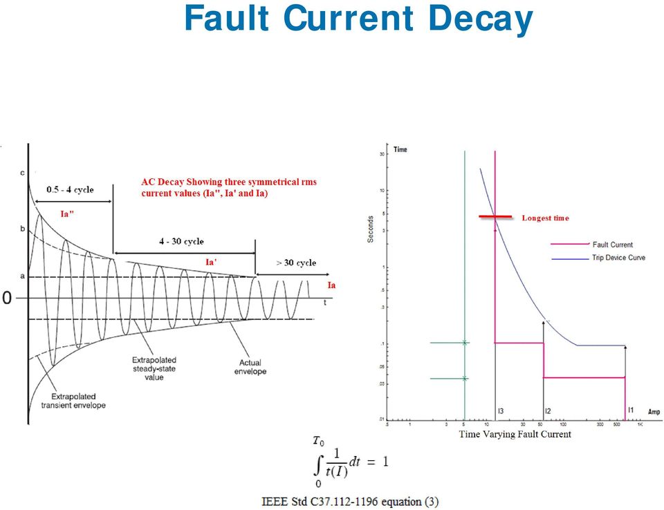
12 Fault Current Including AC & DC Decay

13 Short-Circuit Study for Arc Flash A Short-Circuit Study can be used to determine any or all of the following: Maximum and Minimum Short-circuit current levels Prefault voltage values should be considered Positive and Negative Impedance Tolerance Adjustments Actual fault current values should be used including decaying contributions for medium voltage systems Operating Conditions and System Configurations which may not be otherwise observed for regular SC studies

14 Reactance Representation for Utility and Synchronous Machine for AF ½ Cycle 1 ½ to 4 Cycle 30 Cycle Utility X d X d X d Turbo Generator X d X d Xd Hydro-Gen with Amortisseur winding X d X d Xd Condenser X d X d α Synchronous Motor X d X d α

15 Fault Current Decay
16 Fault Current Recording

17 Overcurrent Protection and Coordination Principles

18 Definition Overcurrent Coordination A systematic study of current responsive devices in an electrical power system.

19 Objective To determine the ratings and settings of fuses, breakers, relay, etc. To isolate the fault or overloads.

20 Coordination Limit the extent and duration of service interruption Selective fault isolation Provide alternate circuits

21 Protection Prevent injury to personnel Minimize damage to components Quickly isolate the affected portion of the system Minimize the magnitude of available short-circuit
22 Spectrum Of Currents Load Current Up to 100% of full-load % (mild overload) Overcurrent Abnormal loading condition (Locked-Rotor) Fault Current Fault condition Ten times the full-load current and higher Arc Fault Currents Between 95 to 38% of bolted fault currents
23 Coordination t C D B A A C D B I
24 Protection vs. Coordination Coordination is not an exact science Compromise between protection and coordination Reliability Speed Performance Economics Simplicity
25 Fixed Points Points or curves which do not change regardless of protective device settings: Cable damage curves Cable ampacities Transformer damage curves & inrush points Motor starting curves Generator damage curve / Decrement curve SC maximum and minimum fault points
26 t Capability / Damage Curves I 2 t I 2 t I 2 t I 22 t Gen Motor Xfmr Cable I
27 Cable Protection The actual temperature rise of a cable when exposed to a short circuit current for a known time is calculated by: A = Ι log T t T Where: A= Conductor area in circular-mils I = Short circuit current in amps t = Time of short circuit in seconds T 1 = Initial operation temperature (75 0 C) T 2 =Maximum short circuit temperature (150 0 C)
28 Cable Short-Circuit Heating Limits Recommended temperature rise: B) CU C
29 Transformer Categories I, II
30 (49) I 2 T t LR O/L MCP t s (51) 200 HP Starting Curve MCP (50) LRA s LRA asym
31 Fuse Protective Devices Overload Heater Thermal Magnetic Low Voltage Solid State Trip Electro-Mechanical Motor Circuit Protector (MCP) Relay (50/51 P, N, G, SG, 51V, 67, 49, 46, 79, 21, )
32 Fuse Types Expulsion Fuse (Non-CLF) Current Limiting Fuse (CLF) Electronic Fuse (S&C Fault Fiter)
33 Minimum Melting Time Curve Total Clearing Time Curve
34 Molded Case CB Thermal-Magnetic Magnetic Only Motor Circuit Protector (MCP) Integrally Fused (Limiters) Current Limiting High Interrupting Capacity Non-Interchangeable Parts Insulated Case (Interchange Parts) Types Frame Size Poles Trip Rating Interrupting Capability Voltage
35 Thermal Maximum Thermal Minimum Magnetic (instantaneous)
36 Overcurrent Relay Time-Delay (51 I>) Short-Time Instantaneous ( I>>) Instantaneous (50 I>>>) Electromagnetic (induction Disc) Solid State (Multi Function / Multi Level) Application
37 Operation Technology, Inc. Workshop Notes: Protective Device Coordination
38 Relay Coordination Time margins should be maintained between T/C curves Adjustment should be made for CB opening time Shorter time intervals may be used for solid state relays Upstream relay should have the same inverse T/C characteristic as the downstream relay (CO-8 to CO-8) or be less inverse (CO-8 upstream to CO-6 downstream) Extremely inverse relays coordinates very well with CLFs
39 Arc Flash Analysis Methods and Mitigation
40 Analysis Methods for Arc Flash Hazards NFPA 70E 2009 Standard for Electrical Safety in the Workplace IEEE a Guide for Performing Arc Flash Hazard Calculations
41 Arc Flash Incident Video
42 Arc Flash Incident Video
43 Arc Flash Incident Video
44 AF Analysis Considerations Possible Arc Fault Locations Line side arc faults Load side arc faults Arc Flash Analysis Worst Case Scenarios Maximum bolted short-circuit fault current Minimum bolted short-circuit fault current Arcing Current Variation Incident Energy at 100% of arcing current Incident Energy at 85% of arcing current
45 Analysis of AF Results Arc Flash Analysis Scope 100s or 1000s of Buses High/Medium/Low Voltage Systems Multiple Operating Configurations Dozens of Multiple Scenarios to be considered
46 Analysis of AF Results Determine Which Protective Device Clears the Arc Fault Is it the first upstream device in all cases? Determine the Locations with Special Analysis Conditions Ibf is less than 700 or higher than 106,000 Amps The bus nominal kv less than kv The feeder source has capacity less than 125 kva (may not have enough energy to generate the arc)
47 Methods to Mitigate the Incident Energy Methods to Reduce the Fault Clearing Time Improving coordination settings of OC PDs. Type 50 protective devices (Instantaneous) Arc Flash light sensors Maintenance mode (switch) Differential protection Zone selective interlocking protection (ZSIP) Methods to Increase the Working Distance Remote racking of breakers/remote switching Use of Hot Sticks
48 Methods to Mitigate the Incident Energy Methods to Reduce the Short-Circuit Current Current limiting fuses and circuit breakers Current limiting reactors, Isolating Transformers High resistance grounding Methods to Reduce the Energy Exposure Arc resistant switchgear Arc shields Infrared scanning, Partial Discharge and or Corona Cameras
49 Improving Over-Current Device Coordination Settings Purpose is to isolate the fault with the nearest upstream over-current protective device Arc flash results are extremely dependent on coordination settings Unnecessarily high time dial settings for type 51 over-current devices Selection of fuses with faster total clearing time characteristic curves can reduce the energy significantly
50 Fault Clearing Time is 37 cycles with current time dial settings Incident Energy released is greater than 27 cal/cm² Category 4 Arcing current through A 50/51 1
51 Fault Clearing Time = 10 cycles with lower time dial settings Incident Energy released is less than 8 cal/cm² Category 2 Arcing current through A 50/51 1
52 Fuse Total Clearing Time based on 3.5 ka Arc Fault
53 Incident Energy Released for Each Fuse
54 Type 50 Protective Device Relays with instantaneous settings Molded case circuit breakers Insulated case breakers Power circuit breakers with instantaneous direct acting trip elements
55 Type 50 PD Advantages Fast acting to reduce the fault clearing time since it can operate within 3 to 6 cycles Commonly available for most MV and LV applications Cost effective and do not require special installations Already installed in electrical system and may only require adjustments to reduce the incident energy
56 Type 50 Protective Devices
57 Type 50 PD Drawbacks To achieve coordination with downstream elements, upstream source Protective Devices have longer time delays (do not have instantaneous protection) The arcing current magnitude passing through the Type 50 protective device must be higher than the device s instantaneous pickup setting
58 Selective Coordination introduces time delays Type 50 PD Drawbacks
59 Maintenance Mode Very fast acting trip device reduces the Fault Clearing Time (FCT) Are designed to pickup under very low arcing current values (instantaneous pickup setting is very low) Does not require complicated installation and will effectively protect locations downstream from the trip unit with maintenance mode
60 Maintenance Mode Normal Operating Mode
61 Normal Operating Mode
62 Normal Operating Mode
63 Maintenance Mode
64 Maintenance Mode ON
65 Maintenance Mode Drawbacks System will not have coordination during the maintenance period because of reduced instantaneous pickup settings Does not increase equipment protection unless the maintenance mode is ON May not protect certain zones where energized equipment tasks may be performed
66 Zone Selective Interlocking Protection (ZSIP) Reduced arc fault clearing times Zone selection is accomplished by means of hard wired communication between trip units Only the trip unit closest to the fault will operate within instantaneous since upstream units are restrained by the unit closest to the fault Equipment and personnel arc fault protection
67 Normal Coordination Settings
68 Arc Faults at different bus levels without ZSIP
69 ZSIP hard-wired communication for restraining upstream trip units
70 Arc Flash at different bus levels using ZSIP (observe the reduced energy)
71 ZSIP Drawbacks May take a bit longer to operate than type 50 devices because of the inherent time delay required for the ZSI logic operation If system is not coordinated, ZSIP does not necessarily force coordination and other upstream devices may operate before the device closest to the fault Arcing current must still be above short time pickup
72 Arc Flash Light Sensors Detect the light emitted by the arc Very fast operation (5 to 10 ms) after the light is detected Provide comprehensive zone or individual cubicle arc flash protection (doors open or closed) when correctly applied Light sensor protection can be worn at time of task being performed for additional safety
73 Light Sensors
74 Kema-Laboratory Tests 50 ka ms Arc Fault Clearing Time
75 Arc Flash without Light Sensors
76 Kema-Laboratory Tests 50 ka ms Arc Fault
77 Kema-Laboratory Tests 50 ka Arc Fault with 50ms Fault Clearing Time
78 Kema-Laboratory Tests 50 ka Arc Fault with 50ms Fault Clearing Time
79 Arc Flash Light Sensor Drawbacks Nuisance trips caused by light emitted from sources other than electrical arcs (can be remedied by using a more robust approach by combining over-current and light sensors) Positioning of the light sensors poses a possible problem if they are obstructed or blocked and cannot see the light emitted by the arc
80 Light Sensor and Over-Current Relay Combination
81 Differential Protection Short Arc Fault Clearing Times Differential protection can operate (relay plus breaker) within 4 to 6 cycles Relay can operate within ½ to 3 cycles Maintain coordination between protective devices upstream and downstream from the Differential Protection Zone Differential protection provides continuous equipment arc flash protection
82 Generator Differential Relay
83 Bus Differential Relay
84 Bus Diff Protection vs. OC Relay Fault I = ka OC Protection FCT = sec Fault I = 51.2 ka Diff Protection FCT = sec
85 Differential Protection Drawbacks Nuisance trips caused by transformer inrush currents which are seen by relay as internal faults - the magnetizing current has particularly high second order harmonic content which can be used to restrain or desensitize the relay during energizing Higher equipment and installation costs - relatively higher costs when compared to traditional over-current protective devices Limited zone of protection for differential ct nodes
86 Current Limiting Methods Current Limiting Fuses Current Limiting Circuit Breakers Current Limiting Reactors Isolating transformers High Resistance Grounding
87 Current Limiting Fuses Current limiting fuses can operate in less than ½ cycle Current limiting action is achieved as long as the magnitude of the arcing current is within the current limiting range Current limitation curves (peak let-through curves) are needed in order to check if the fuse can limit the current Can be very effective at reducing the incident energy if properly used
88 Current Limiting Action I p Current (peak amps) I p t a = t c t m t a = Arcing Time t m = Melting Time t c = Clearing Time t m t a Time (cycles) I p = Peak Current I p = Peak Let-thru Current t c
89 Current Limiting Action
90 Current Limiting Fuse Drawbacks Current limiting action is achieved as long as the magnitude of the arcing current is within the current limiting range Can be thermally damaged and have altered characteristics Needs spares (which may be expensive) and there is not indication of the type of fault. Energization on pre-existing fault = another blown fuse
91 Current Limiting Reactors Isolating Transformers Current limiting reactors can help to reduce the available fault current and thus reduce the available energy Isolating transformers help to reduce high ka short-circuit levels (down to less than 10 ka). Isolating transformers add impedance between the main switchboard and the smaller panels fed from it. The shortcircuit available at the switchboard may be considerably higher
92 Increasing the Working Distance Hot Sticks Remote Racking Remote Switching
93 Remote Racking/Remote Switching Are used to increase the personal space between the potential source of the arc and the electrician Can be combined with high strength plastic shields to reduce the effects of the arc flash/blast
94 Remote Racking/Remote Switching
95 Remote Racking/Remote Switching
96 Remote Racking/Remote Switching
97 Remote Racking/Remote Switching
98 Mitigating/Avoiding the Incident Energy Arc Resistant Switchgear Arc Flash Shields
99 Arc Resistant Switchgear Funneling or re-directing the incident energy away from the personal space Special design and construction allows the front of the equipment to experience low levels of energy Arc flash may still be very severe and equipment will suffer considerable damage
100
101 Arc Resistant Switchgear
102 Upcoming Arc Flash Analysis Standards/Guidelines Changes
103 Arc Flash Analysis Standards/Guidelines Changes How will these standards affect your AF Analysis Calculations? IEEE 1584b IEEE IEEE 1814 NFPA 70E NESC- Utility Models / Testing for utility equipment
104 Arc Flash Analysis Standards/Guidelines Changes Recent Papers on arc flash in Low Voltage Equipment NFPA 70E and IEEE Collaboration to develop / revise current Models DC Arc Flash Calculations
105 NFPA 70E & IEEE1584 Collaboration Efforts Phase I Test Results Refined Equations for Incident Energy Calculations ~ Vertical, Horizontal and Vertical with Barrier Conductor arrangements Effect of Sound ~ ka fault Effect of Light ~ 45,000,000 LUX from Arc Fault Bright day is about 20,000 LUX Arc Blast Pressure Wave Effects ~ 0.9 psi 120 to 200 lbs of force
106 IEEE 1584b - Amendments
107 IEEE 1584b - Amendments Relay Operated Power Circuit Breaker Interrupting times Circuit Breaker Rating and Type Interrupting Time at 60 Hz (cycles) Interrupting Time at 60 Hz (seconds) Low Voltage Molded Case CB 3.0 (used to be 1.5) (used to be 0.025) Low Voltage Insulated Case CB Low Voltage Power CB
108 IEEE 1584b - Amendments
109 IEEE 1584b - Amendments
110 IEEE 1584b - Amendments Main PD AF Results
111 IEEE 1584b - Amendments Results with Main PD Isolation Considered
112 Arc Flash for LV Systems Impact of Arc Flash Events with Outward Convective Flows on Worker Protection Strategies ESW Mike Lang, Member IEEE Ken Jones Member IEEE Thomas Neal, PhD
113 Arc Flash for LV Systems
114 Arc Flash for LV Systems
115 Arc Flash for LV Systems
116 Arc Flash for LV Systems
117 IEEE Analysis Guidelines Define what are the requirements for performing AF analysis Defines the complexity of Systems and the experience required to perform and AF study Educates the Engineering process (how to make conservative assumptions)
118 IEEE 1814 Safety by Design Reduce the Risk by designing safer equipment Samples of better Disconnect Switch Design Including Technology like ZSIP into Unit Substation Design
119 NESC ROP for Amp Meter Base Shorting Wire in Meter Base
120 DC Arc Flash Analysis
121 Methodology for DC Arc Flash DC SC and Arc Flash
122 Methodology for DC Arc Flash DC Arc Flash Basic Concepts
123 DC Arc Power Methodology for DC Arc Flash
124 Methodology for DC Arc Flash Maximum Power Method (2007 IEEE Electrical Safety Workshop) I arc = 0.5 I bf IE m = 0.01 V sys I arc T D arc 2
125 Methodology for DC Arc Flash Detailed Theoretical Calculation Method (2009 IEEE PCIC) (Testing has confirmed the theoretical method) V arc = ( Z g ) I 0.12 arc R arc = ( I 0.88 arc Z g )
126 Methodology for DC Arc Flash V-I Characteristic Curves
127 Methodology for DC AF Arc Energy Equations Power = P E arc arc = V I arc V 2 arc dc I I arc R dc = arc I 2 arc t arc R arc
128 Methodology for DC AF DC Incident Energy Equations for Open Air and Enclosed Configurations E s E = 4 π d arc 2 E 1 = k a E 2 arc + d 2
129 Methodology for DC AF Enclosed DC Arc Fault values a and k Enclosure Width (mm) Height (mm) Depth (mm) a (mm) k Panelboard LV Switchgear MV Switchgear
130 Test System Example using the theoretical method
131 Diff Method Result Comparison Comparison of the Maximum Power Method vs. Theoretical Method DC Arc Flash Method Maximum Power I bf dc (ka) I arc dc (ka) R arc (ohms ) FCT (sec ) I.E. (cal/cm 2 ) N/A Theoretical Method
132 Transient Arc Flash Analysis for Generators
133 Problem Description Arc Flash Incidents near or on Generator Auxiliary Load No Generator Circuit Breaker Long Fault Clearing Time because of continuous generator short-circuit current contribution Trying to determine a practical level of PPE to be used for the task To determine a systematic method to determine the incident energy for systems with high fault current decay
134 System Description
135 System Description
136 Analysis Techniques and Assumptions IEEE 1584 and NFPA 70E do not provide any specific analysis method for such systems The classic IEEE 1584 method utilizes the Bolted fault current to determine the arc fault current The guidelines do not consider any transients or decay in the fault currents
137 Arc Flash Analysis Utility Breaker Operates 6 cycles after Arc Fault is detected
138 Arc Flash Analysis
139 Arc Flash Analysis Scenario ID Arc Flash Method Arcing Current (ka) I.E. (cal/cm 2 ) for 2.0 sec Case 1 Half Cycle (Ia ) Case 2 Four Cycle (Ia ) Case 3 Decay Method (Ia ~ Ia) 21.4 ~
140 Problems with Regular Arc Flash Analysis Method The calculation results show very high incident energy values Results in too much PPE requirements for the task Difficult to estimate the actual energy
141 Benefits from Transient Stability Analysis Determine actual bolted fault current contributions Model actual generator time constants and exciter field discharge strategies Accurate recalculation of the bolted fault current levels for system separation Actual response of the Excitation and Generator Controls
142 Methods of Reducing Generator Fault Current Loss of Excitation Field Discharge Resistor / Crowbar bypass system Negative Field Forcing
143 Exciter Model Used for the Simulations
144 Field Discharge: Short-Circuit Equivalent Circuit Model for Field Discharge Simulation
145 Field Discharge Resistor A Field Discharge Resistor (FDR) is added along with the generator Time Constant (T do )
146 Negative Field Forcing For Negative Field Forcing. The discharge rate is dependent on the value of the negative voltage
147 Transient Stability Scenarios Scenario ID Field Discharge Scheme Simulation Method Bolted Fault 2.0 sec Case 1 None TS 17.7 ka Case 2 Loss of Excitation TS 11.2 ka Case 3 FDR to with RD = RF TS 6.2 ka Case 4 Negative Field Forcing TS with UDM 0.54 ka
148 Fault Current Comparison
149 Incident Energy Determination from TS Results Using Spreadsheet, MathCAD or Matlab to import the bolted fault current values from the Transient Fault Study The IEEE Empirical Equations are used The energy is determined by integrating the incident energy results from each time step up to arbitrary time of exposure (i.e. 2.0 sec)
150 Scenario ID Incident Energy Comparison Field Discharge Scheme I.E. (cal/cm 2 ) for 2.0 sec Case 1 None 40.8 Case 2 Loss of Excitation 33.1 Case 3 FDR to with RD = RF 25.7 Case 4 Negative Field Forcing 19.8
151 Comparison Against Arc Flash I.E. (cal/cm 2 ) for 2.0 sec (Arc Flash with TS) I.E. (cal/cm 2 ) for 2.0 sec (Regular Arc Flash) Highest Results Lowest Results
152 References Generator Field Discharge Methods provided by Wayne Eads of Southern Company Generation IEEE Standard IEEE Recommended Practice for Excitation System Models for Power System Studies IEEE Power System Stability and Control, Prabha Kundur
153 References DC Arc Flash and Shock NFPA 70E ROP Memphis Feb 18, 2010 DC Arc Models and Incident Energy Calculations Paper No. PCIC Award Winning Paper DC Arc Hazard Assessment Phase II Copyright Material Kenectrics Inc., Report No. K RA R00
154 Questions? Questions?
Part 1 System Modeling & Studies for Existing Systems
 Part 1 System Modeling & Studies for Existing Systems Operation Technology, Inc. Copyright 2009 Result of rapid release of energy due to an arcing fault between two conductors. Bus voltages > 208V Temperatures
Arc Flash Hazards. Electrical Hazards. Dan Neeser Field Application Engineer DanRNeeser@Eaton.com. Electrical Hazards 2/18/2015. Shock.
 Arc Flash Hazards Dan Neeser Field Application Engineer DanRNeeser@Eaton.com Electrical Hazards Electrical Hazards Shock Arc Flash Arc Blast 2 1 Arcing Fault Basics 35,000 F Radiant Heat & UV Speed of
ARC FLASH CALCULATIONS & LABELING REQUIREMENTS
 ARC FLASH CALCULATIONS & LABELING REQUIREMENTS Presented by: Edmund Elizalde EYP Mission Critical Facilities, Inc. Slides by: Lonnie Lindell SKM Systems Analysis, Inc. 1 Agenda NEC 110.16 NFPA 70E IEEE
A USERS GUIDE TO ARC RESISTANT LOW VOLTAGE SWITCHGEAR & MOTOR CONTROL ANALYTICAL COMPARISON VS ARC FLASH TEST RESULTS
 A USERS GUIDE TO ARC RESISTANT LOW VOLTAGE SWITCHGEAR & MOTOR CONTROL ANALYTICAL COMPARISON VS ARC FLASH TEST RESULTS By: Gabriel Arce, ABB, San Luis Potosi, Mexico Casey McCollum, ABB, Houston, TX John
Arc Flash Energy Mitigation Techniques
 Arc Flash Energy Mitigation Techniques When short circuits occur on an electrical distribution system, an arc flash event usually forms. These arc flash events can cause dangerous and potentially fatal
Safety By Design. Strategies for Electrical Contractors
 Safety By Design Strategies for Electrical Contractors Introduction Engineering and system design significantly impact worker safety System design provides opportunity to eliminate/minimize workers exposure
Arc Flash Mitigation. Remote Racking and Switching for Arc Flash danger mitigation in distribution class switchgear.
 Arc Flash Mitigation Remote Racking and Switching for Arc Flash danger mitigation in distribution class switchgear. Distance is Safety We will discuss through examples of actual occurrences and possible
Management Systems 10 Electrical Safety Audit 14 PPE 20 Arc Mitigation 22 Hazard Assessment 26
 Management Systems 10 Electrical Safety Audit 14 PPE 20 Arc Mitigation 22 Hazard Assessment 26 Assessing The Hazards Of High and Low Voltage Single-Phase Arc-Flash By Albert Marroquin One common question
PRESENTED AT THE 2011 IEEE IAS PULP & PAPER INDUSTRY TECHNICAL CONFERENCE, NASHVILLE, TN: IEEE 2011 - PERSONAL USE OF THIS MATERIAL IS PERMITTED.
 Arc Flash Energy Reduction Techniques Zone Selective Interlocking & Energy-Reducing Maintenance Switching Christopher G. Walker Senior Member, IEEE Eaton Corporation Moon Township, PA 15108 chrisgwalker@eaton.com
Understanding Arc Flash
 Understanding Arc Flash Presented by Eddie F. Jones, PE 1 2 3 4 5 Five to 10 arc flash explosions occur in electric equipment every day in the United States. This number does not include cases in which
ELECTRICAL SAFETY RISK ASSESSMENT
 ELECTRICAL SAFETY RISK ASSESSMENT The intent of this procedure is to perform a risk assessment, which includes a review of the electrical hazards, the associated foreseeable tasks, and the protective measures
RISK MITIGATION for ELECTRICAL WORK. Feb 2013 San Diego CA
 RISK MITIGATION for ELECTRICAL WORK Feb 2013 San Diego CA Agenda I. RISK Define the Risks Arc Flash Review II. MITIGATION 3 Easy Steps New Designs Vs. Existing Systems III. DUKE UNIVERSITY EXAMPLE I. Risk
BRANDON AND CLARK INC. // SCOTT W. CLARK, P.E. ELECTRICAL CONTINUING EDUCATION ARC FLASH - NFPA 70E
 BRANDON AND CLARK INC. // SCOTT W. CLARK, P.E. ELECTRICAL CONTINUING EDUCATION ARC FLASH - NFPA 70E Training is not a substitute for following corporate safety guidelines. Always refer to the latest safety
Arc Flash Mitigation & Selective Co-ordination
 Arc Flash Mitigation & Selective Co-ordination Michael Hodder March 2015 Overview This seminar will provide information on: Mitigating arc flash hazards Selective Coordination What can we do to make these
DIMENSIONING OF CURRENT TRANSFORMERS FOR PROTECTON APPLICATION
 ÿþ üûúùø öõöôùóùõò CT Dimensioning DIMENSIONING OF CURRENT TRANSFORMERS FOR PROTECTON APPLICATION Application note GER3973 1 CT Dimensioning ÿþ üûúùø öõöôùóùõò GER-3973 Application note ÿþ üûúùø öõöôùóùõò
Electronic Trip Circuit Breaker Basics Circuit Breaker Application Guide Class 0600
 Electronic Trip Circuit Breaker Basics Circuit Breaker Application Guide Class 0600 Data Bulletin 0600DB1104 03/2012 Retain for future use. Electronic Trip Circuit Breaker Basics 0600DB1104 Table of Contents
ZONE SELECTIVE INTERLOCKING (ZSI) APPLICATION AND TESTING GUIDE SIEMENS WL UL489 AND UL1066 AIR CIRCUIT BREAKERS
 APPLICATION AND TESTING GUIDE SIEMENS WL UL489 AND UL1066 AIR CIRCUIT BREAKERS") Definition: Zone Selective Interlocking (ZSI) - A method which allows two or more ground fault breakers to communicate with each other so that a short circuit or ground fault will be cleared by the breaker
Definition: Zone Selective Interlocking (ZSI) - A method which allows two or more ground fault breakers to communicate with each other so that a short circuit or ground fault will be cleared by the breaker
Proper Application of 415V Systems in North American Data Centers. A White Paper from the Experts in Business-Critical Continuity
 Proper Application of 415V Systems in North American Data Centers A White Paper from the Experts in Business-Critical Continuity Introduction Increasing pressure to reduce operating expenses and be more
Sentron Series Circuit Breakers
 Sentron Series Circuit Breakers Siemens Sentron Series circuit breakers are available in nine frame sizes: ED, FD, JD, LD, LMD, MD, ND, PD, and RD. Sentron Series circuit breakers have a wide range of
misconceptions about arc-flash hazard assessments
 misconceptions about arc-flash hazard assessments There are some common misconceptions about Arc-Flash Hazard Assessments which reduce the effectiveness of the Assessments and can increase electrical hazards.
Circuit Breakers and Switchgear. Thomas Greer Director of Engineering TLG Services
 Circuit Breakers and Switchgear Thomas Greer Director of Engineering TLG Services Presentation Outline Switchgear Definition Overcurrent Protection Devices Circuit Breaker Trip Curves and Coordination
Short Circuit Current Calculations
 Introduction Several sections of the National Electrical Code relate to proper overcurrent protection. Safe and reliable application of overcurrent protective devices based on these sections mandate that
CIRCUIT BREAKER INTERRUPTING CAPACITY AND SHORT-TIME CURRENT RATINGS
 CIRCUIT BREAKER INTERRUPTING CAPACITY AND SHORT-TIME CURRENT RATINGS David D. Roybal, P.E. Senior Member, IEEE Eaton Electrical 3697 Mount Diablo Boulevard Lafayette, CA 94549 Abstract Low-voltage circuit
ARC FLASH HAZARD MITIGATION. Industrial Tests, Inc. [indtests.com]
![ARC FLASH HAZARD MITIGATION. Industrial Tests, Inc. [indtests.com]](/thumbs/29/13595142.jpg "ARC FLASH HAZARD MITIGATION. Industrial Tests, Inc. [indtests.com]") ARC FLASH HAZARD MITIGATION ARC FLASH HAZARD MITIGATION NWHA TECHNICAL SEMINAR May 17, 2012 Richard D Reese Power Systems Manager Industrial Tests, Inc. Rocklin, California [Dick@indtests.com; 916-660-2837]
ARC FLASH HAZARD MITIGATION ARC FLASH HAZARD MITIGATION NWHA TECHNICAL SEMINAR May 17, 2012 Richard D Reese Power Systems Manager Industrial Tests, Inc. Rocklin, California [Dick@indtests.com; 916-660-2837]
How to reduce exposure to arc flash hazards
 GE Energy Industrial Solutions How to reduce exposure to arc flash hazards Multiple solutions for new and existing facilities imagination at work Multiple Issues Today s power system engineer must not
Electrical Predictive and Preventative Maintenance
 Electrical Predictive and Preventative Maintenance Electrical and mechanical equipment is subject to failure at the worst possible time for no apparent reason. - Mose Ramieh III There are two types
2004 TRANSMISSION SYSTEMS SEMINAR MEDIUM VOLTAGE, METAL-CLAD ARC RESISTANT SWITCHGEAR: ENHANCING WORKPLACE SAFETY
 2004 TRANSMISSION SYSTEMS SEMINAR MEDIUM VOLTAGE, METAL-CLAD ARC RESISTANT SWITCHGEAR: ENHANCING WORKPLACE SAFETY Thomas P. McNamara, P.E. Manager, Development Engineering ABB Inc. Power Technologies Medium
The Importance of the X/R Ratio in Low-Voltage Short Circuit Studies
 The Importance of the X/R Ratio in Low-Voltage Short Circuit Studies DATE: November 17, 1999 REVISION: AUTHOR: John Merrell Introduction In some short circuit studies, the X/R ratio is ignored when comparing
Low Voltage Switchgear
 Arc Resistant Switchgear n Insulated and isolated bus n Separation barriers and top venting n Breaker shutters 12 SWITCHGEAR Arc resistant metal-enclosed low voltage switchgear is an optional product offering
SPECIAL TOPICS ON GROUND FAULT PROTECTION AND PROTECTION COORDINATION IN INDUSTRIAL AND COMMERCIAL POWER SYSTEMS
 SPECIAL TOPICS ON GROUND FAULT PROTECTION AND PROTECTION COORDINATION IN INDUSTRIAL AND COMMERCIAL POWER SYSTEMS Claudio S. Mardegan claudio.mardegan@engepower.com www.engepower.com Phone: 55 3579-8777
The Three A s of Arc Flash
 The Three A s of Arc Flash Gary H. Fox, PE Senior Specification Engineer In 2007 GE conducted a survey of industry professionals working in facilities related to the oil and gas industry, pulp and paper
A Guide to Performing An Arc Flash Hazard Assessment Using Power Analysis Software
 A Guide to Performing An Arc Flash Hazard Assessment Using Power Analysis Software Abstract: The nature of explosive equipment failures, and the rate of serious burn injuries in the electrical industry
OVERCURRENT & EARTH FAULT RELAYS. To study the protection of equipment and system by relays in conjunction with switchgear.
 OVERCURRENT & EARTH FAULT RELAYS Objective: To study the protection of equipment and system by relays in conjunction with switchgear. Theory: The function of a relay is to detect abnormal conditions in
ARC FLASH HAZARD OVERVIEW. Presented August 13, 2015 WWOA Lake Michigan District by Mead & Hunt, Inc.
 ARC FLASH HAZARD OVERVIEW Presented August 13, 2015 WWOA Lake Michigan District by Mead & Hunt, Inc. ARC FLASH EXPERIENCE Christopher J. DeWaal, MS, MEM, PE, LEED AP, HACCP How did I get involved? A client
STANDARDS AND RATINGS FOR THE APPLICATION OF MOLDED CASE, INSULATED CASE, AND POWER CIRCUIT BREAKERS
 STANDARDS AND RATINGS FOR THE APPLICATION OF MOLDED CASE, INSULATED CASE, AND POWER CIRCUIT BREAKERS David D. Roybal, P.E. Senior Member, IEEE Cutler-Hammer, Inc. 3697 Mount Diablo Boulevard Lafayette,
NFPA 70E 2012 Rolls Out New Electrical Safety Requirements Affecting Data Centers
 NFPA 70E 2012 Rolls Out New Electrical Safety Requirements Affecting Data Centers A market position paper from the experts in Business-Critical Continuity TM Executive Summary Electrocutions are the fourth
Mitigation of Arc-Flash Hazards and Reduction of Costs by Selective Arc-Flash Protection
 Mitigation of Arc-Flash Hazards and Reduction of Costs by Selective Arc-Flash Protection L. Kumpulainen, S. Dahl J. Ma Vamp Ltd, Finland Vamp Ltd, China 1 ABSTRACT This paper describes causes and characteristics
7. Reactive energy compensation
 593 7. Reactive energy compensation 594 7. REACTIVE ENERGY COMPENSATION Reactive energy compensation is an important element for reducing the electricity bill and improving the quality of the electrical
Choosing the Best Solution for Reducing Arc Energy
 CONVENTION SESSION HANDOUT Choosing the Best Solution for Reducing Arc Energy Terry L. Schiazza, Business Development Manager Square D / Schneider Electric SESSION #11 Independent Electrical Contractors
Secondary Unit Substations
 14 SWITCHGEAR Secondary Unit Substations Overview Siemens offers a wide variety of unit substation designs to meet customer requirements. A unit substation consists of one or more transformers mechanically
Arc Terminator Active Arc-Resistant Switchgear
 Arc Terminator Active Arc-Resistant Switchgear Increasing safety and productivity by extinguishing internal arcing faults within the switchgear. The Square D Arc Terminator from Schneider Electric offers
The following table shows approximate percentage wise the
 SHORT-CIRCUIT CALCULATION INTRODUCTION Designing an electrical system is easy and simple, if only the normal operation of the network is taken into consideration. However, abnormal conditions which are
FFI. Advances in Medium and Low Voltage Power Distribution ESS Metron Expo and Technical Seminars. Presented By: Greg Pelster & Robert Schmid
 Advances in Medium and Low Voltage Power Distribution ESS Metron Expo and Technical Seminars Presented By: Greg Pelster & Robert Schmid FFI Ferrie, Franzmann Industries LOW VOLTAGE SWITCHGEAR & LOW VOLTAGE
Typical Data Requirements Data Required for Power System Evaluation
 Summary 66 Carey Road Queensbury, NY 12804 Ph: (518) 792-4776 Fax: (518) 792-5767 www.nepsi.com sales@nepsi.com Harmonic Filter & Power Capacitor Bank Application Studies This document describes NEPSI
Transmission Protection Overview
 Transmission Protection Overview 2012 Hands-On Relay School Brian Smyth Schweitzer Engineering Laboratories Pullman, WA Transmission Line Protection Objective General knowledge and familiarity with transmission
Digital Energy ITI. Instrument Transformer Basic Technical Information and Application
 g Digital Energy ITI Instrument Transformer Basic Technical Information and Application Table of Contents DEFINITIONS AND FUNCTIONS CONSTRUCTION FEATURES MAGNETIC CIRCUITS RATING AND RATIO CURRENT TRANSFORMER
Line Reactors and AC Drives
 Line Reactors and AC Drives Rockwell Automation Mequon Wisconsin Quite often, line and load reactors are installed on AC drives without a solid understanding of why or what the positive and negative consequences
Current Limiting Protector For Systems rated 2.8-38kV and continuous currents through 5000A.
 Current Limiting Protector For Systems rated 2.8-38kV and continuous currents through 5000A. Arc Flash and Arc Blast reduction Network protection SCADA adaptable Indoor/outdoor application Professional
Fault Characteristics in Electrical Equipment
 1. Introduction Proper design and installation of electrical equipment minimizes the chance of electrical faults. Faults occur when the insulation system is compromised and current is allowed to flow through
21 st Century Facilities
 Electrical Testing 21 st Century Facilities Facility Owners face tough challenges 24 X 7 reliability needed Non linear loads cause harmonics VFD Computers Switching transients disrupt operations Less customer
Low Voltage Transformer Through-Fault Protection: A System Approach
 Data Bulletin 7400DB1001 Nashville, TN USA Low Voltage Transformer Through-Fault Protection: A System Approach Introduction Low Voltage Transformer Protection Criteria NEC Article 450 Transformers and
Arc Flash Mitigation. Executive summary. by Antony Parsons, Ph.D., P.E.
 by Antony Parsons, Ph.D., P.E. Executive summary Arc flash events can result in significant injury to workers, including severe burn injuries. The most effective arc flash safety programs are not those
How To Choose A Transformer
 Consider open loop MV network as an example source 1 source 2 NC NC NC or NO main MV switchboard A B Detail design of substation NC NC NC NO NC NC switchboard 1 switchboard 2 switchboard 3 MV MV MV LV
Fortune Oregon Data Center Increases Reliability with a High Resistance Grounding System
 Fortune Oregon Data Center Increases Reliability with a High Resistance Grounding System Cory David Smith, Project Manager, ECOM Engineering Inc., and David Lawrence Smith, Principal, ECOM Engineering
Introduction to Arc Flash
 Introduction to Arc Flash Worker Training of Electrical Hazards Including Arc Flash SH-16614-7 This material was produced under grant number SH-16614-7 from the Occupational Safety and Health Administration,
Mission Critical Data Center Systems
 Mission Critical Systems Mission Critical/ Electrical Distribution Systems Data center electrical distribution designs are rapidly evolving, driven by needs such as increasing power densities, energy efficiency,
LIMITING SHORT-CIRCUIT CURRENTS IN MEDIUM-VOLTAGE APPLICATIONS
 LIMITING SHORT-CIRCUIT CURRENTS IN MEDIUM-VOLTAGE APPLICATIONS Terence Hazel Senior Member IEEE Schneider Electric 38050 Grenoble France Abstract The power requirements for large industrial sites is increasing.
Guidelines on the Short Circuit Current Rating for Industrial Control Panels
 usa.siemens.com/sccr Guidelines on the Short Circuit Current Rating for Industrial Control Panels Technical Paper for Practical Applications White Paper I October 2014 As per NEC Edition 2014, and UL508A
UL 508A Industrial Control Panels Power Distribution and Control. Lunch & Learn Training. 2002 Eaton Corporation. All rights reserved.
 UL 508A Industrial Control Panels Power Distribution and Control Lunch & Learn Training 2002 Eaton Corporation. All rights reserved. Agenda Who is UL and what role do they play? What is the UL 508A Standard?
Fusible Disconnect Switch
 Circuit Breakers Circuit breakers are used in panelboards and switchboards to provide circuit protection and provide a means of energizing and de-energizing a circuit. Siemens Sentron molded case circuit
HAZARDS, INCLUDING SHOCK, ARC FLASH AND FIRE
 Appendix B-2 - Electrical Safety In Design Final Report TECHNOLOGIES THAT REDUCE LIKELIHOOD OF INJURY FROM ELECTRICAL HAZARDS, INCLUDING SHOCK, ARC FLASH AND FIRE The following are technologies that reduce
Rule 5.500 Fast Track Analysis for National Life Insurance Co.
 Rule 5.500 Fast Track Analysis for National Life Insurance Co. For a 500 kw Solar array to be located at 155 Northfield Street in Montpelier, Vermont Green Mountain Power Pam Allen Date: 5/31/13 SECTION
CAPACITOR BANK TESTING SWP
 1. PURPOSE AND SCOPE The purpose of this Standard Work Practice (SWP) is to standardise and prescribe the method for testing Capacitor Banks including capacitors, tuning reactors and inrush limiting reactors.
System Grounding and Ground-Fault Protection Methods for UPS-Supplied Power Systems
 System Grounding and Ground-Fault Protection Methods for -Supplied Power Systems Bill Brown, P.E., Square D Critical Power Competency Center 1. INTRODUCTION The use of solid grounding for -supplied power
Application of Four-Pole Circuit Breakers within Data Centers
 Application of Four-Pole Circuit Breakers within Data Centers December 2013/AT324 by Frank Waterer, Fellow Engineer, Schneider Electric Engineering Services Make the most of your energy SM Revision #1
CT Application Guide for the 489 Generator Management Relay
 g GE Power Management Technical Notes CT Application Guide for the 489 Generator Management Relay GE Publication No. GET-8402 Copyright 2002 GE Power Management Introduction A protection scheme operates
Unified requirements for systems with voltages above 1 kv up to 15 kv
 (1991) (Rev.1 May 2001) (Rev.2 July 2003) (Rev.3 Feb 2015) Unified requirements for systems with voltages above 1 kv up to 15 kv 1. General 1.1 Field of application The following requirements apply to
NFPA 70E Updates Affect Your Most Valuable Assets
 NFPA 70E Updates Affect Your Most Valuable Assets EXECUTIVE SUMMARY Electrocution is a well-known hazard associated with direct contact with electrical energy. According to the U.S. Department of Labor,
INTRODUCTION TO SYSTEM PROTECTION. Hands-On Relay School 2012
 INTRODUCTION TO SYSTEM PROTECTION Hands-On Relay School 2012 CONGRATULATIONS On choosing the field of system protection. It is an exciting, challenging profession. System protection has changed considerably
New standardized approach to arc flash protection
 New standardized approach to arc flash protection Samuel Dahl Juha Arvola Tero Virtala Arcteq Relays Ltd Arcteq Relays Ltd Arcteq Relays Ltd Wolffintie 36 F 11 Wolffintie 36 F 11 Wolffintie 36 F11 65200
Alternate Methods to Short Circuit Breaker Coordination
 Alternate Methods to Short Circuit Breaker Coordination Nguyen Perez, PE Senior Electrical Engineer 2600 Douglas Road, Suite 301 Coral Gables, Florida 305.529.1515 (p) www.brplusa.com Importance in Healthcare
DC TRANSMISSION BASED ON VOLTAGE SOURCE CONVERTERS
 DC TRANSMISSION BASED ON VOLTAGE SOURCE CONVERTERS by Gunnar Asplund, Kjell Eriksson, Hongbo Jiang, Johan Lindberg, Rolf Pålsson, Kjell Svensson ABB Power Systems AB Sweden SUMMARY Voltage Source Converters
2012 NFPA 70E. Ten Most Important Changes. John A. DeDad
 2012 NFPA 70E Ten Most Important Changes John A. DeDad GE Energy Management 41 Woodford Avenue Plainville, CT 06062 USA 860-747-7344 John.dedad@ge.com Abstract The 2012 Edition of NFPA 70E, Standard for
2a. IEM Indoor Metal Clad Medium Voltage Switchgear 15KV 16346-1. 2a. Section 16346 INDOOR METAL CLAD MEDIUM VOLTAGE SWTICHGEAR (Std.
 2a. IEM Indoor Metal Clad Medium Voltage Switchgear 15KV 16346-1 2a. Section 16346 INDOOR METAL CLAD MEDIUM VOLTAGE SWTICHGEAR (Std. Relays) Part 1 General 1.1 CONDITIONS AND REQUIREMENTS: A. Refer to
Submit shop drawings for equipment provided under this section Shop drawings shall indicate:
 Section 16435 - SWITCHBOARDS Introduction Part 1 - General Reference The work under this section is subject to requirements of the Contract Documents including the General Conditions, Supplementary Conditions,
Bypass transfer switch mechanisms
 Power topic #6013 Technical information from Cummins Power Generation transfer switch mechanisms > White paper By Gary Olson, Director, Power Systems Development This paper describes the configuration
SUBJECT: How to wire a motor starter Number: AN-MC-004 Date Issued: 2/08/2005 Revision: Original
 SUBJECT: How to wire a motor starter Number: AN-MC-004 Date Issued: 2/08/2005 Revision: Original A motor starter is a combination of devices to allow an induction motor to start, run and stop according
Technical Guide. SKM Arc Flash Line Side vs. Load Side
 SKM Arc Flash Line vs. Load The option of choosing the line-side or the load-side arc flash incident energy for arc flash labels is an important decision when performing an arc flash hazard analysis. When
Power System Selectivity: The Basics of Protective Coordination
 Feature Power System Selectivity: The Basics of Protective Coordination by Gary H. Fox, PE GE Specification Engineer The intent of this article is to provide a brief primer about the essence of coordinating
Tmax MCCBs. Molded case circuit breakers. Tmax
 Molded case circuit breakers Introduction ABB is once again demonstrating its commitment to new product development and its superiority in product performance. Never before has the industry seen such high
Bulletin 150 Smart Motor Controllers SMC-3 Smart Motor Controller
 Overview/Modes of Operation Bulletin 150 Smart Motor Controller The SMC-3 is a compact, simple to use, solid-state motor controller designed to operate 3-phase motors. It features a built-in overload relay
A Comparison of Contemporary Electrical Distribution Equipment Standards. San Francisco IEEE Industry Applications Society May 26, 2009
 A Comparison of Contemporary Electrical Distribution Equipment Standards San Francisco IEEE Industry Applications Society May 26, 2009 What are Standards? Clearly defined performance characteristics Based
Data Bulletin. Circuit Breaker Characteristic Trip Curves and Coordination Class 0600 TRIP CURVES AND COORDINATION CIRCUIT BREAKER TRIP CURVES
 Data Bulletin Bulletin No. 000DB0 August 0 Cedar Rapids, IA, USA Class 000 TRIP CURVES AND COORDINATION CIRCUIT BREAKER TRIP CURVES Thermal Tripping Characteristics agnetic Tripping Characteristics A coordination
100% Stator Ground Fault Detection Implementation at Hibbard Renewable Energy Center. 598 N. Buth Rd 3215 Arrowhead Rd
 100% Stator Ground Fault Detection Implementation at Hibbard Renewable Energy Center Introduction Roger Hedding Steven Schoenherr, P.E. ABB Inc. Minnesota Power 598 N. Buth Rd 3215 Arrowhead Rd Dousman,
Low Voltage Circuit Breakers. Arc flash hazards
 Low Voltage Circuit Breakers Arc flash hazards Index Low voltage selectivity with ABB circuit breakers Introduction... 2 Definitions, acronyms and terms used... 3 Electrical arcs and their dangerous effects
What are the basic electrical safety issues and remedies in solar photovoltaic installations?
 What are the basic electrical safety issues and remedies in solar photovoltaic installations? Presented by: Behzad Eghtesady City of Los Angeles Department of Building and Safety Topics Covered Photovoltaic
Arc Flash Avoidance and its Application to Overhead Traveling Cranes
 Arc Flash Avoidance and its Application to Overhead Traveling Cranes Whitepaper August 2012 Jason Wellnitz, Controls Product Manager Material Handling Numerous technical papers, bulletins, magazine articles
UNIVERSITY OF WASHINGTON Facilities Services Design Guide. Electrical. Switchboards. Basis of Design. Design Evaluation
 Basis of Design This section applies to the design relating to low voltage switchboards. Design Criteria UW Class N1 facilities main switchboards shall be rear accessible. The main, tie and feeder breakers
Grounding of Electrical Systems NEW CODE: Grounding and Bonding
 Grounding of Electrical Systems NEW CODE: Grounding and Bonding Presented By Scott Peele PE Grounding of Electrical Systems Outline Defining the Terms Why should I Ground? Types of Grounding Systems Separately
Eaton s E-Series protective relay family
 E-Series protective relays Feeder distribution relays Motor relays Transformer relays Generator relays Eaton s E-Series protective relay family Microprocessor-based design Eaton s E-Series relay family
! WARNING Arc Flash and Shock Hazard Appropriate PPE Required
 Arc Flash Hazard Labeling Do s and Don ts! WARNING Arc Flash and Shock Hazard Appropriate PPE Required 11' - 3" Flash Hazard Boundary 9 cal/cm2 Flash Hazard at 18 inches #3 PPE Level Cotton underwear plus
High Efficiency Motor Protection. Industry White Paper
 High Efficiency Motor Protection Industry White Paper 2 High Efficiency Motor Protection High Efficiency Motor Protection - An Overview Electric motor protection depends on the accurate selection of overloads,
Permissible ambient temperature Operation Storage, transport
 The Sitras PRO combined DC protective unit and controller is used in the power supply for DC railways in mass transit and main-line systems up 3,000 V DC. It protects DC switch gear and contact line systems
RM4TG20 three-phase network control relay RM4-T - range 200..500 V
 Characteristics three-phase network control relay RM4-T - range 200..500 V Complementary [Us] rated supply voltage Output contacts Setting accuracy of time delay Delay at power up Measuring cycle Marking
What s up with Arc Flash?
 What s up with Arc Flash? Presented by Mark Haskins, CSP Practical Safety Solutions, LLC CONN OSHA Breakfast Roundtable February 18, 2014 2014 Practical Safety Solutions, LLC What is Arc Flash? Definition
Analyzing Electrical Hazards in the Workplace
 Analyzing Electrical Hazards in the Workplace By Dennis K. Neitzel, CPE AVO Training Institute, Inc. The need for analyzing electrical hazards in the workplace has been recognized by a small segment of
Molded Case Circuit Breakers, Motor Protection Circuit Breakers, and Motor Circuit Protectors. Technical Data
 Molded Case Circuit Breakers, Motor Protection Circuit Breakers, and Motor Circuit Protectors Technical Data Table of Contents Introduction... 4 Definitions... 5 Product Range... 8 Product Line Overview...11
Mini Circuit Breakers, Fuse Blocks, and Electronic Circuit Protection
 Technical Data Mini Circuit Breakers, Fuse Blocks, and Electronic Circuit Protection Topic Page 1489-M Miniature Circuit Breakers 2 1492-SP Supplementary Protectors 15 1492-D Circuit Breakers 27 188 Regional
PROPER SELECTION OF CONTROL CIRCUIT TRANSFORMERS WHITE PAPER BULLETIN 1497, 1497A, AND 1497B
 WHITE PAPER PROPER SELECTION OF CONTROL CIRCUIT TRANSFORMERS BULLETIN 1497, 1497A, AND 1497B CONTROL CIRCUIT TRANSFORMERS The proper selection of the control circuit transformers is important for suitable
Instruction Bulletin. MCS025 Sync-Check Module Installation Sheet
 Instruction Bulletin 63230-216-244B1 LaVergne, TN, USA MCS025 Sync-Check Module Installation Sheet Retain for future use. DANGER HAZARD OF ELECTRIC SHOCK, EXPLOSION, OR ARC FLASH Only qualified electrical