20 ACRE UBATC SITE ( 650' x 1,350') UINTAH BASIN MASTER PLAN VERNAL CAMPUS. Architects Engineers Program and Construction Managers
|
|
|
- Shana Powers
- 9 years ago
- Views:
Transcription
1 20 ACRE UBATC SITE ( 650' x 1,350') UINTAH BASIN MASTER PLAN VERNAL CAMPUS Architects Engineers Program and Construction Managers

2 BUILDING MAINTENANCE BUILDING TRADES CLASSROOMS COMMONS/CIRCULATION COMPUTER LAB CULINARY ARTS DRAFTING ELEVATOR FACULTY HEALTH HEAVY EQUIPMENT INDUSTRIAL SAFTY IT MEDIA PETROLIUM TECHNOLOGY RESTROOMS SCIENCES STAIRS TIERED CLASSROOM WELDING +

3 14.8 ACRES FUTURE EXPANSION SHOP EXPANSION TRUCK DRIVING RANGE PEDESTRIAN UNDERPASS FUTURE PARKING PRELIMINARY SITE PLAN NEW CLASSROOM BUILDING AND INDUSTRIAL TECHNOLOGY FACILITY DFCM NO DECEMBER 20th, 2006 Not to Scale

4 SECOND FLOOR SCALE = 1/16 = 1 DIESEL SHOP SCALE = 1/16 = 1 FIRST FLOOR SCALE = 1/16 = 1 CLASSROOM COMPONET ~ SCHEMATIC DESIGN NEW CLASSROOM BUILDING AND INDUSTRIAL TECHNOLOGY FACILITY DFCM NO

5 Geotechnical Engineering Study Uintah Basin Applied Technology School Proposed Classroom, Shop, and Library Buildings Vernal, Utah Prepared for: Division of Facilities and Construction Management Salt Lake City, UT

6 December 20, 2006 DFCM Attn: Lyle Knudsen 4110 State Office Building Salt Lake City, UT RE: Geotechnical Engineering Study Uintah Basin Applied Technology Center Classroom, Shop, and Administration Buildings Vernal, Utah Dear Mr. Knudsen: This report presents our geotechnical findings for the proposed buildings at approximately 1855 West 500 North in Vernal, Utah. The location of the site and proposed building location is shown on Figures 1 and 2, respectively. The objectives of this study were to define subsurface soil and groundwater conditions and then prepare recommendations regarding site grading and foundations. A summary of our findings include: The site soils will not adequately support conventional spread footings. Highly compressible soft clay soils were encountered from 3.5 to 10 feet below the surface. Options include using soil improvement technology, deep foundations, or overexcavating compressible soils (10 to 13-feet) and replacing with structural fill. We recommend conventional spread footings placed over a rammed aggregate rock pier system (Geopier). At the Uintah High School, north of site, all soft soils were over-excavated and replaced with granular fill. Native soil consisted of the following typical sequence: 8 to 12-inches of organic silty clay (topsoil), then a medium stiff clay to 4-feet, below which is a highly compressible sandy clay to 8.5-feet below the surface. Beneath the sandy clay is a two feet layer of medium stiff clay then a gravelly cobble layer to full depth explored (14.5-feet). Additional investigations are needed for future buildings and to address ground and surface water concerns. If you have questions regarding this report or desire additional information, please contact me at (801) Sincerely, Todd Touchard, P.E. HARRIS & ASSOCIATES 265 East 100 South, Suite 350 Salt Lake City, Utah (801) FAX: (801) www. harris-assoc.com

7 1.0 INTRODUCTION PROPOSED CONSTRUCTION FIELD AND LABORATORY INVESTIGATION Field Investigation Laboratory Investigation SITE CONDITIONS Surficial Soils Subsoils Groundwater DESIGN RECOMMENDATIONS Foundations Estimated Settlement Lateral Resistance and Earth Pressure Site Soil Classification & Coefficient Liquefaction & Faults Pavement Design Concrete Slabs on Grade Subgrade Stabilization Soil Chemistry GENERAL CONSTRUCTION PROCEDURES AND RECOMMENDATIONS Foundation Excavations Soil Special Inspection, Fill Compaction & Installation Granular Fill Road base LIMITATIONS East 100 South, Suite 350 Salt Lake City, Utah (801) FAX: (801) www. harris-assoc.com

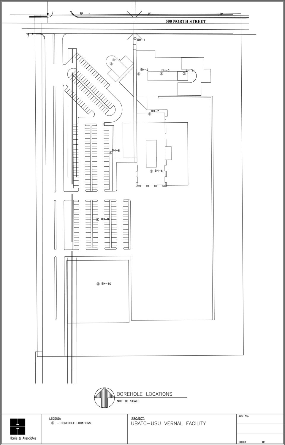
8 Geotechnical Investigation Uintah Basin Applied Technology College December 20, 2006 Page INTRODUCTION This report presents our findings for the proposed campus building located at approximately 1855 West 500 North in Vernal, Utah. The location of the site and proposed building locations are shown on Figure 1 and 2, respectively. The objectives of this study were to define subsurface soil and groundwater conditions then give recommendations regarding site grading, foundation, and pavements. To accomplish the objectives, a field investigation program and laboratory analysis of soil was conducted. The field investigation included ten boreholes using a hollow stem auger drill rig. Borehole locations are presented in Figure 2. The borehole logs are shown in Figure 3A-3J. A legend to log symbols and additional soil information is provided in Figure 4. Individual laboratory tests (Figure 5A to 5D) and lab summary (Figure 6A to 6B) are attached. If the proposed structure, location of structures, or proposed use of pavements changes, our office shall be notified to review and potentially change recommendations contained in this report. 2.0 PROPOSED CONSTRUCTION Three buildings consisting of standard masonry, concrete, and steel construction. Buildings will be two story with anticipated loads of 2.0 to 5.0 kips/lf and moderate column loads on the order of 150 to 200 kips. 3.0 FIELD AND LABORATORY INVESTIGATION 3.1 Field Investigation To define the subsurface soil and groundwater conditions, we conducted ten boreholes (BH-1 through BH-10) shown on Figure 2, in the Appendix. Boreholes were completed to required depth or auger refusal. Groundwater was encountered in all excavations. The boreholes were located within the areas of the proposed building lots to best illustrate the general subsurface conditions. Soil samples were obtained from the boreholes at a minimum depth of two feet below grade and then at the five foot intervals or at significant change in soil strata. Soils were classified in the field and later verified with laboratory testing. The sampling was done in general accordance with ASTM D-420. The subsurface conditions disclosed by the field investigation are discussed in Section East 100 South, Suite 350 Salt Lake City, Utah (801) FAX: (801) www. harris-assoc.com

9 Geotechnical Investigation Uintah Basin Applied Technology College December 20, 2006 Page 2 The descriptions of soil encountered in the excavations are presented in Figures 3A to 3J in the Appendix. Sampling information and other pertinent field data and observations are also included on the Borehole Logs. A Soil Classification Chart defining the terms and symbols used on the logs, is provided as Figure 4 in the Appendix. 3.2 Laboratory Investigation For soil classification and engineering properties, the samples obtained from exploratory borings were laboratory tested. The tests include: Moisture Content Soil Density Partial Sieve Analysis Torvane Shear Test Atterberg Limits Consolidation Tests Laboratory test data is shown on the individual Logs and is attached. 4.0 SITE CONDITIONS The site slopes moderately downward to the south and east. The site is being used for agricultural purposes and is planted in alfalfa. 4.1 Surficial Soils The surficial soil consists of a dark brown silty clay with organics (Topsoil). These clays will exhibit very poor engineering properties. The depth of topsoil ranges from 8 to 12-inches thick. 4.2 Subsoils The subsoils soils at the site were found to be relatively consistent across the site. Beneath the surface topsoil, a medium stiff silty clay layer extends from 3 to 5 feet. Beneath which is a highly compressible sandy clay layer that ranges to depths of 8 to 10 feet below the surface. Below the sandy clay, a medium stiff clay layer (1 to 2 feet thick) typically occurs then a gravel cobble layer was observed to full depth explored (14.5-feet). Water well logs in the area show that the cobble layer extends to at least 25 feet below the surface. 265 East 100 South, Suite 350 Salt Lake City, Utah (801) FAX: (801) www. harris-assoc.com

10 Geotechnical Investigation Uintah Basin Applied Technology College December 20, 2006 Page Groundwater Groundwater was encountered in all of the boreholes. Groundwater elevations at the time of the field exploration are shown on borehole logs and Table 1 below. The groundwater elevation is controlled by field drains installed by the Bureau of Reclamation. Subsurface drains were constructed with open ended concrete pipes or perforated plastic tubing two to three feet below the surface. Drains were installed to lower groundwater to allow farming and daylights in the Steinaker Canal at the southeast corner of the property. The determination of the suitability and existing condition of these drains are beyond the scope of this investigation. At a minimum, these drains need to be inspected and maintained in order to prevent high groundwater related problems form occurring. We recommend a groundwater drainage system evaluation study. Approximately midway along the west boundary of the entire property, surface water flows across the property to the southeast. A shallow groundwater gravel aquifer daylights in this area. The surface water typically only flows during the spring. A drainage system will need to be designed to remediate this problem. Seasonal fluctuation of groundwater levels is anticipated to occur in this area. Depending on site grading and time of construction, groundwater and soft soils may be encountered at footing and pavement subgrades. It is beyond the scope of this report to monitor and determine depth of potential highest groundwater levels. Subgrade Stabilization is discussed in Section 5.8. Table 1. Groundwater Elevation (depth below surface) Borehole BH-1 BH-2 BH-3 BH-4 BH-5 BH-6 Groundwater Elevation DESIGN RECOMMENDATIONS The following recommendations have been developed on the basis of the previously described project characteristics and subsurface conditions. A technical design review should be made by this office if actual loads are greater than anticipated or if there is any change in project criteria, including building location on the site. 5.1 Foundations A conventional shallow spread foundation system can not be used without soil improvement. The in-situ compressible sandy clay layer is estimated to settle on the order of 4-inches under typical foundation loads. This sandy clay layer exists 3 to 5 feet beneath the surface and extends to depths of 8.5 to 13.5 feet below the surface. Options include removing the clay layer to underlying gravelly cobble and replacing with structural fill, conducting a soil improvement technology, or installing a deep foundation system. 265 East 100 South, Suite 350 Salt Lake City, Utah (801) FAX: (801) www. harris-assoc.com

11 Geotechnical Investigation Uintah Basin Applied Technology College December 20, 2006 Page 4 We researched different systems and recommend placing rammed aggregate piers beneath conventional spread footings. Intermediate Foundation Recommendations Rammed aggregate piers, or Geopier elements, may be used as an alternative to massive overexcavation and recompaction or deep foundations. Geopier-reinforced soils improve the subgrade below conventional spread footings and reduce the compressibility of the underlying soil. Geopier soil reinforcement elements are constructed by drilling a 24 or 30-inch diameter hole, removing a volume of soil, and then building a bottom bulb of clean, open-graded stone using a beveled, high-energy tamper. The Geopier shaft is constructed on top of the bottom bulb using well-graded highway base course stone placed in thin lifts (12 inches compacted thickness). Geopier shaft lengths typically range between 8 and 20 feet as measured from footing subgrade. The result of construction is a reinforced zone of soil directly under footings that allows for the construction of shallow spread footings proportioned for a relatively high bearing pressure. Geopier elements are spaced singly or in close groups beneath interior footings to support concentrated column loads. Beneath continuous footings, Geopier elements typically are spaced at 6 to 12 feet on center depending on loads, soil conditions, and other design requirements. Geopier Foundation Company was contacted to provide preliminary recommendations for the design of foundations at this site. Their preliminary recommendations include a maximum allowable bearing pressure of 5,000 pounds per square foot for spread footings bearing on a Geopier-reinforced subgrade. This pressure is a composite pressure, applicable across the entire area of the footing. The allowable pressure may be increased by 1/3 for consideration of short-term seismic loading. Geopier elements would be 30 inches in diameter and would extend through the upper clay to the underlying gravel to limit total and differential settlement to 1 inch and ½ inch, respectively. Geopier soil reinforcement should be designed and constructed by an installer licensed by the Geopier Foundation Company, Inc. The installer should provide a Geopier layout and detailed design calculations sealed by a professional engineer licensed in the State of Utah. The design calculations should demonstrate that Geopier soil reinforcement is designed to control long-term settlement to magnitudes within the criteria for this project. The licensed Geopier installer for the State of Utah is Geopier Northwest. They can be contacted at The design parameters should be verified by a full-scale Geopier modulus test (similar to a pile load test) performed in the field. The Geotechnical Consultant should be retained to monitor the modulus test and subsequent installation of production Geopier elements. 265 East 100 South, Suite 350 Salt Lake City, Utah (801) FAX: (801) www. harris-assoc.com

12 Geotechnical Investigation Uintah Basin Applied Technology College December 20, 2006 Page Estimated Settlement Settlement is based on the contractor following the recommendations provided in this report and by Geopier Foundation Company. The anticipated total settlement of the foundation will be on the order of 1-inch, assuming light to moderate loads. Differential settlement is not expected to exceed 1/2-inch. This is assuming the design recommendations are followed. 5.3 Lateral Resistance and Earth Pressure For the determination of lateral resistance for footings placed on a rammed aggregate piers, a friction value of 0.35 may be used for ultimate lateral resistance. The follow equivalent fluid pressures are based on using granular soil backfill (135 pcf). Backfill depth is not expected to exceed 3-feet in depth next to classroom. Compact backfill to 90% of relative maximum density (ASTM D1557) within 3-feet of basement walls. Equivalent Fluid Density (pcf) Active At-Rest Passive Static Seismic Site Soil Classification & Coefficient The site is classified as E, according to the International Building Code (IBC) 2006 edition. Site coefficients provided by the USGS web page for 2006 IBC are provided in Table 2 below. Table 2. Design Acceleration Coefficients Design acceleration of short periods (0.2 sec) Design acceleration for 1 second period S s F a S MS S DS S 1 F v S M1 S D Liquefaction & Faults Liquefaction of a soil is defined as the condition when, a saturated, loose, cohesion-less, (fine sand-type) soils have a sudden, large decrease, in their ability to support. This is because of excessive pore water pressure, which develops during a seismic event. Cohesive (clay type) soils and dry soils typically do not liquefy during a seismic event. If the buildings were to be placed on conventional spread footings, the saturated soft sandy clay is expected to have a moderate to low potential for settlement. The rammed aggregate piers will lessen the liquefaction settlement potential. The site is located approximately 16 to 18 miles southwest of a suspected section of the Diamond Gulch faults, as depicted on the Utah Quaternary Fault and Fold Map (Utah 265 East 100 South, Suite 350 Salt Lake City, Utah (801) FAX: (801) www. harris-assoc.com

13 Geotechnical Investigation Uintah Basin Applied Technology College December 20, 2006 Page 6 Geological Survey, 2003). This 20 km fault has a dip direction of NE and SW. The faulted deposits are from the Tertiary age and the slip rate is <0.2 mm/yr. 5.6 Pavement Design The following pavement designs are recommended: Roadway Areas (medium to light truck traffic): Asphalt: 4-inches Base: 6-inches roadbase Subbase 12-inches granular fill Geogrid BX1100 Over: Native undisturbed granular soil or properly prepared granular fill Parking Areas: Asphalt: 3-inches Base: 6-inches roadbase Subbase 12-inches of granular fill Over: Native undisturbed granular soil or properly prepared granular fill A geogrid, such as Tensar BX1100 (or equivalent), shall be placed between granular fill and native undisturbed soil in roadway traffic areas. Geogrid is to be placed as per manufacturer s recommendations. Compaction should be done in 8-inch loose lifts and tested to 95% relative to laboratory maximum density (ASTM D1557). If the native soils are soft or if groundwater is encountered follow recommendation in Section 5.8. Native soils below the pavement section shall be proof rolled with heavy equipment to tighten any loose soil at the surface and identify soft spots before placing any portion of the pavement section. If soft spots are encountered they shall be addressed as per Section 6.0 below. 5.7 Concrete Slabs on Grade It is anticipated that fill will be used to create level building floor elevations. Due to high groundwater and soft soils, is not recommended to place floor slabs lower than existing elevations. The additional loads of bookshelves, maintenance equipment, trucks, and up to six feet of fill will cause the floor slab to settle as much as 1-inch. We recommend placing all floor slabs over a geopier grid system that will limit settlement below ½-inch. A Geogrid will be required such as Tensar BX1100 to be placed between geopiers and floor slabs. The spacing and depths of rammed aggregate piers can be provided by Geopier Northwest ( ). Interior and exterior concrete slabs on grade should be placed over 4 minimum, of ½ to 1 diameter, poorly graded, clean, free-draining gravel. Below the 4 gravel layer shall be properly 265 East 100 South, Suite 350 Salt Lake City, Utah (801) FAX: (801) www. harris-assoc.com

14 Geotechnical Investigation Uintah Basin Applied Technology College December 20, 2006 Page 7 compacted granular fill or natural undisturbed native soil. For moisture sensitive floor coverings, a plastic vapor barrier should be installed beneath the concrete slab. 5.8 Subgrade Stabilization If construction practices or weather conditions during the placement of the fill caused the native fine grain soils to become soft in floor slab or footings areas one of the following should be done: Remove areas where soils are disturbed and place an additional 18-inches of granular fill (crushed or pit-run gravel), gradation requirements are shown in Section 6.4, then place footings or begin placing subbase for pavements. Or place Geotextile grid between the undisturbed native soil and fill material to achieve proper compaction of the fill layers. Follow manufacture s recommendations for lap length and installation. Manufacturer, type, and properties of geotextile grid used shall submitted to geotechnical engineer for approval prior to construction. If soft spots or disturbed soils are encountered, contact our office to verify the appropriate corrective action to be used. 5.9 Soil Chemistry Soil was tested for ph and sulfates levels to determine corrosion potential of concrete and buried utilities. The Sulfate and ph levels tested are considered to not be injurious to concrete. Lab tests are shown in Table 3 below. Table 3. Soil Chemical Testing Sample Location Sulfates (mg/l) ph B-2 at 2.5 below surface GENERAL CONSTRUCTION PROCEDURES AND RECOMMENDATIONS The guidelines outlined below address the geotechnically-related construction concerns for this project. 6.1 Foundation Excavations Prior to placement of the foundations and floor sections, all areas that will support foundation loads or pavements should be inspected to insure that all loose, soft or otherwise undesirable material is removed and that the structures will bear on satisfactory material. All topsoil, fill and other deleterious materials underneath the proposed structure and pavement should be removed. Harris & Associates or an approved geotechnical engineer must be contacted to inspect each excavation before the placement piers, footings, or foundations. 265 East 100 South, Suite 350 Salt Lake City, Utah (801) FAX: (801) www. harris-assoc.com
, gradation requirements are shown in Section 6.")
15 Geotechnical Investigation Uintah Basin Applied Technology College December 20, 2006 Page 8 If unsatisfactory material pockets are encountered in the excavation, the undesirable material should be removed and the elevation re-established by backfilling, which can be done with lean concrete or a properly compacted granular fill. All foundation excavations should be protected against any detrimental change in condition such as disturbance, rain and freezing. Surface runoff should be directed away from the excavation and not allowed to pond. If possible, all footing concrete should be poured the same day as the excavation is made. If this is not practical, the foundation excavation should be adequately protected and foundation placement should take place as soon as possible. 6.2 Soil Special Inspection, Fill Compaction & Installation Soil Special Inspections are required for all fill placed greater than 12-inches. A Special Inspector shall provide the following inspections as outlined in the 2006 IBC: 1. Verify materials below footings are adequate to achieve design bearing capacity (periodic). 2. Verify excavations are extended to proper depth and have reached proper material (periodic). 3. Perform classification and testing of controlled fill materials (periodic). 4. Verify use of proper materials, densities, and lift thickness during placement and compaction of controlled fill (continuous). 5. Prior to placement of controlled fill, observe subgrade and verify site has been prepared properly (periodic). 6. Additional Special Inspections will be required to verify rammed aggregate piers are properly installed to correct depth, spacing, and compaction (continuous). All fill beneath load bearing areas should be compacted to at least 95 percent of the Modified Proctor maximum density (ASTM D 1557). Fill placed in rammed aggregate piers will be verified using a cone penetration test (ASTM D 6951). Compaction tests by a qualified testing agency should be taken on each lift to insure the required compaction is being achieved. The compaction should be accomplished by placing the fill in 8- inch loose lifts and mechanically compacting each lift to the specified minimum density. Field density tests should be performed on each lift as necessary to insure that compaction is being achieved. 265 East 100 South, Suite 350 Salt Lake City, Utah (801) FAX: (801) www. harris-assoc.com

16 Geotechnical Investigation Uintah Basin Applied Technology College December 20, 2006 Page 9 Table 3. Recommend Minimum Frequency of Soil Testing During Construction. Test Method Frequency ASTM D 1557 Modified Moisture Start of project for each type of soil being compacted Density Relationship (proctor) and when material appears to change in color or particle size distribution. ASTM D 422 Particle Size Analysis ASTM D 2922 Nuclear Density Compaction Testing ASTM D 2922 Nuclear Density Compaction Testing Roadways. ASTM D 6951 Dynamic Cone Penetration Test Before import fill is delivered to project. Every 100 linear feet of backfill, each lift, or a minimum of 8 tests for project. One test per 800 s.f. of roadway subbase and roadbase placed. Each rammed aggregate pier to verify compaction of aggregates and depth of piers. 6.3 Granular Fill Granular soils free of organics, debris, or other deleterious materials are recommended for use as granular fill at this site. Granular fill is defined as a well graded sand and gravel material (pitrun or crushed gravel), with less than 15 percent passing the #200 sieve and no particles greater than 4 inches in maximum dimension. Granular fill should not exhibit plasticity characteristics. Approved soil types as defined using the Unified Soil Classification are considered to be GW, GP, or GM or combinations thereof. See Figure 4 for soil type definitions. Granular fill to have a minimum CBR value of 60%. Contractor is to provide soil classification and sieve analysis submittal for final approval to Geotechnical Engineer. 6.4 Road base For the base material directly below pavement, we recommend a granular soil free of organic or other deleterious material. We recommend a sand and fractured gravel material with between 5 and 12 percent passing the #200 sieve and no particles greater than approximately ¾ -inches in maximum dimension. Roadbase should have a minimum CBR value of 80%. Contractor is to provide soil classification and sieve analysis submittal for final approval to Geotechnical Engineer. 265 East 100 South, Suite 350 Salt Lake City, Utah (801) FAX: (801) www. harris-assoc.com

17 Geotechnical Investigation Uintah Basin Applied Technology College December 20, 2006 Page LIMITATIONS The recommendations provided herein were developed by evaluating the information obtained from the boreholes. The borehole data reflects the subsurface conditions only at the specific location at the particular time designated on the borehole log. Soil and ground water conditions may differ from conditions encountered at the actual borehole locations. The nature and extent of any variation in the borehole may not become evident until during the course of construction. If variations do appear, it may become necessary to re-evaluate the recommendations of this report after we have observed the variation. Our professional services have been performed, our findings obtained, and our recommendations prepared in accordance with generally accepted geotechnical engineering principles and practices. This warranty is in lieu of all other warranties, either expressed or implied. Enclosures: Appendix : Figure 1 - Project Location Map Figure 2 - Location Boreholes Site Map Figure 3A-3B - Logs of Boreholes Figure 4 - Soil Classification Chart Laboratory Analysis Data 265 East 100 South, Suite 350 Salt Lake City, Utah (801) FAX: (801) www. harris-assoc.com

18 TN MN (11.7 E) Scale 1 : 25, ft m " = 2,083.3 ft Data Zoom 12-0

19
20 265 East 100 South Salt Lake City, UT Project Name: Vernal UBATC Location: 1900 West 500 North, Vernal, Utah Drilling Method: Hollow Stem Auger Drill Rig Elevation: Existing Remarks: Slotted PVC installed Project No.: Client: DFCM Date Drilled: 10/24/2006 Water Level: 6'-2" BOREHOLE -1 Page: 1 of 1 Graphical Log Water Level DESCRIPTION DEPTH FT. SAMPLE TYPE BLOWS/6-inch MOISTURE (%) % PASSING #200 DRY DENSITY (PCF) Liquid Limit (%) Plastic Limit (%) REMARKS Topsoil 0' to 1' soft, moist, dark-brown/black Ground Surface 0 Silty Clay (CL): 1' to 4.5' medium stiff, moist, brown w/rust color mottling SPT 3,2,2 Silty Clay (CL): 8.5' to 10' very soft, fine to medium sand, saturated, light brown 5 SPT 1,1, Grades to: Sandy Clay (CL) 1,1, Silty Clay (CL): 8.5' to 10' medium stiff, saturated, brown Cobbles and Gravel w/trace Silt and Sand (GP): 10' to 14' very dense, fine to coarse sand, fine to coarse gravel, cobbles to 6", saturated, brown SPT 68,50-2" Auger Refusal at 14' SPT=Stanard Split Spoon CAL=2"ID =Modified 20 FIGURE 3A
: 8.")
21 265 East 100 South Salt Lake City, UT Project Name: Vernal UBATC Location: 1900 West 500 North, Vernal, Utah Drilling Method: Hollow Stem Auger Drill Rig Elevation: Existing Remarks: Slotted PVC installed Project No.: Client: DFCM Date Drilled: 10/24/2006 Water Level: 6'-3" BOREHOLE -2 Page: 1 of 1 Graphical Log Water Level DESCRIPTION DEPTH FT. SAMPLE TYPE BLOWS/6-inch MOISTURE (%) % PASSING #200 DRY DENSITY (PCF) Liquid Limit (%) Plastic Limit (%) REMARKS Topsoil 0' to 1' soft, moist, dark-brown/black Ground Surface 0 Silty Clay (CL): 1' to 4' medium stiff, moist, brown w/rust color mottling 4,4, Silty Clay w/trace Sand (CL): 4' to 8' very soft, fine to medium sand, saturated, light brown 5 Grades to: 1,1, Sandy Clay (CL) Silty Clay w/trace Gravel (CL): 8' to 12' medium stiff,fine gravel, saturated, reddish brown 5,7,7 10 Cobbles and Gravel w/trace Silt Sand (GP): 12' to 15' very dense, fine to coarse sand, fine to coarse gravel, cobbles to 6", saturated, brown CAL 18,75 15 Auger Refusal at 15' SPT=Standard Split Spoon CAL=2"ID =Modified 20 FIGURE 3B
22 265 East 100 South Salt Lake City, UT Project Name: Vernal UBATC Location: 1900 West 500 North, Vernal, Utah Drilling Method: Hollow Stem Auger Drill Rig Elevation: Existing Remarks: Slotted PVC installed Project No.: Client: DFCM Date Drilled: 10/24/2006 Water Level: 4'-11" BOREHOLE -3 Page: 1 of 1 Graphical Log Water Level DESCRIPTION DEPTH FT. SAMPLE TYPE BLOWS/6-inch MOISTURE (%) % PASSING #200 DRY DENSITY (PCF) Liquid Limit (%) Plastic Limit (%) REMARKS Topsoil 0' to 1' soft, moist, dark-brown/black Ground Surface 0 Silty Clay (CL): 1' to 5' medium stiff, moist, brown w/rust color mottling 2,2, Silty Clay w/trace Sand (CL): 5' to 10' very soft, fine to medium sand, saturated, light brown 5 1,1, Grades to: Sandy Clay (CL) 1,1,1 Sandy Clay w/some Gravel (SC): 10' to 13' fine to coarse sand, fine to coarse gravel, soft, saturated, light brown 10 CAL 2,3, Cobbles and Gravel w/trace Silt Sand (GP): 13' to 13.5' very dense, fine to coarse sand, fine to coarse gravel, cobbles to 6", saturated, brown CAL 2" Auger Refusal at 13.5' SPT=Standard Split Spoon CAL=2"ID =Modified 20 FIGURE 3C
23 265 East 100 South Salt Lake City, UT Project Name: Vernal UBATC Location: 1900 West 500 North, Vernal, Utah Drilling Method: Hollow Stem Auger Drill Rig Elevation: Existing Remarks: Slotted PVC installed Project No.: Client: DFCM Date Drilled: 10/24/2006 Water Level: 4'7" BOREHOLE -4 Page: 1 of 1 Graphical Log Water Level DESCRIPTION DEPTH FT. SAMPLE TYPE BLOWS/6-inch MOISTURE (%) % PASSING #200 DRY DENSITY (PCF) Liquid Limit (%) Plastic Limit (%) REMARKS Topsoil 0' to 1' soft, moist, dark-brown Ground Surface 0 Silty Clay (CL): 1' to 3.5' medium stiff, moist, brown w/rust color mottling 3,3, Silty Clay w/trace Sand (CL): 3.5' to 8.5' very soft, fine to medium sand, saturated, light brown Grades to: 5 1,2, Sandy Clay (CL) Silty Clay w/trace Gravel (CL): 8.5' to 9.5' medium stiff,fine gravel, saturated, reddish brown Cobbles and Gravel w/trace Silt Sand (GP): 9.5' to 10' very dense, fine to coarse sand, fine to coarse gravel, cobbles to 6", saturated, brown 10 7,10, 50-4" Auger Refusal at 10' 15 SPT=Standard Split Spoon CAL=2"ID =Modified 20 FIGURE 3D
24 265 East 100 South Salt Lake City, UT Project Name: Vernal UBATC Location: 1900 West 500 North, Vernal, Utah Drilling Method: Hollow Stem Auger Drill Rig Elevation: Existing Remarks: Slotted PVC installed Project No.: Client: DFCM Date Drilled: 10/24/2006 Water Level: 7' BOREHOLE -5 Page: 1 of 1 Graphical Log Water Level DESCRIPTION DEPTH FT. SAMPLE TYPE BLOWS/6-inch MOISTURE (%) % PASSING #200 DRY DENSITY (PCF) Liquid Limit (%) Plastic Limit (%) REMARKS Topsoil 0' to 1' soft, moist, dark-brown Ground Surface 0 Silty Clay (CL): 1' to 4.5' medium stiff, moist, brown w/rust color mottling 3,3, Silty Clay w/some Sand (CL): 4.5' to 8.5' very soft, fine to medium sand, saturated, light brown 5 1,1,1 Silty Clay(CL): 8.5' to 12' medium stiff, saturated, reddish brown 10 4,9, Cobbles and Gravel w/trace Silt Sand (GP): 12' to 13' very dense, fine to coarse sand, fine to coarse gravel, cobbles to 6", saturated, brown Auger Refusal at 13' 15 SPT=Standard Split Spoon CAL=2"ID =Modified 20 FIGURE 3E
25 265 East 100 South Salt Lake City, UT Project Name: Vernal UBATC Location: 1900 West 500 North, Vernal, Utah Drilling Method: Hollow Stem Auger Drill Rig Elevation: Existing Remarks: Slotted PVC installed Project No.: Client: DFCM Date Drilled: 10/25/2006 Water Level: 4' BOREHOLE -6 Page: 1 of 1 Graphical Log Water Level DESCRIPTION DEPTH FT. SAMPLE TYPE BLOWS/6-inch MOISTURE (%) % PASSING #200 DRY DENSITY (PCF) Liquid Limit (%) Plastic Limit (%) REMARKS Topsoil 0' to 1' soft, moist, dark-brown Ground Surface 0 Silty Clay (CL): 1' to 3' medium stiff, moist, brown w/rust color mottling Silty Clay w/trace Sand (CL): 3' to 13.5' very soft, fine to medium sand, saturated, light brown 1,2, ,1, Grades to: Sandy Clay with depth 10 0,1, Cobbles and Gravel w/trace Silt Sand (GP): 13.5' to 14.5' very dense, fine to coarse sand, fine to coarse gravel, cobbles to 6", saturated, brown CAL " Auger Refusal at 14.5' SPT=Standard Split Spoon CAL=2"ID =Modified 20 FIGURE 3F
26 265 East 100 South Salt Lake City, UT Project Name: Vernal UBATC Location: 1900 West 500 North, Vernal, Utah Drilling Method: Hollow Stem Auger Drill Rig Elevation: Existing Remarks: Project No.: Client: DFCM Date Drilled: 10/25/2006 Water Level: Initial Water Level at 6' BOREHOLE -7 Page: 1 of 1 Graphical Log Water Level DESCRIPTION DEPTH FT. SAMPLE TYPE BLOWS/6-inch MOISTURE (%) % PASSING #200 DRY DENSITY (PCF) Liquid Limit (%) Plastic Limit (%) REMARKS Topsoil 0' to 1' soft, moist, dark-brown Silty Clay (CL): 1' to 8' medium stiff, saturated, brown Ground Surface 0 3,3,3 5 color changes to brown with dark grey mottling 5,9,9 Silty Clay w/some Sand (CL): 8' to 10' very soft, fine to medium sand, saturated, light brown 10 1,2,4 Cobbles and Gravel w/trace Silt Sand (GP): 10.5' to 11' very dense, fine to coarse sand, fine to coarse gravel, cobbles to 6", saturated, brown Auger Refusal at 11' 15 SPT=Standard Split Spoon CAL=2"ID =Modified 20 FIGURE 3G
27 265 East 100 South Salt Lake City, UT Project Name: Vernal UBATC Location: 1900 West 500 North, Vernal, Utah Drilling Method: Hollow Stem Auger Drill Rig Elevation: Existing Remarks: Project No.: Client: DFCM Date Drilled: 10/25/2006 Water Level: Initial Water Level at 4' BOREHOLE -8 Page: 1 of 1 Graphical Log Water Level DESCRIPTION DEPTH FT. SAMPLE TYPE BLOWS/6-inch MOISTURE (%) % PASSING #200 DRY DENSITY (PCF) Liquid Limit (%) Plastic Limit (%) REMARKS Topsoil 0' to 1' soft, moist, dark-brown Silty Clay (CL): 1' to 4.5' medium stiff, saturated, brown Ground Surface 0 3,4, Silty Clay w/trace Sand (CL): 4.5' to 8.5' very soft, organics and roots, fine to medium sand, saturated, light brown 5 1,1, Silty Clay (CL): 8.5' to 11.5' medium stiff, saturated, brown 10 2,5,3 End of Sampling and Drilling at 11.5' 15 SPT=Standard Split Spoon CAL=2"ID =Modified 20 FIGURE 3H
28 265 East 100 South Salt Lake City, UT Project Name: Vernal UBATC Location: 1900 West 500 North, Vernal, Utah Drilling Method: Hollow Stem Auger Drill Rig Elevation: Existing Remarks: Parking lot Project No.: Client: DFCM Date Drilled: 10/25/2006 Water Level: BOREHOLE -9 Page: 1 of 1 Graphical Log Water Level DESCRIPTION DEPTH FT. SAMPLE TYPE BLOWS/6-inch MOISTURE (%) % PASSING #200 DRY DENSITY (PCF) Liquid Limit (%) Plastic Limit (%) REMARKS Topsoil 0' to 1' soft, moist, dark-brown Ground Surface 0 Silty Clay (CL): 1' to 4.5' medium stiff, moist, brown SPT 4,4,5,7 22 SPT 2,3, End Sampling and Drilling at 4.5' SPT=Standard Split Spoon CAL=2"ID =Modified 20 FIGURE 3I
29 265 East 100 South Salt Lake City, UT Project Name: Vernal UBATC Location: 1900 West 500 North, Vernal, Utah Drilling Method: Hollow Stem Auger Drill Rig Elevation: Existing Remarks: Parking Lot Project No.: Client: DFCM Date Drilled: 10/25/2006 Water Level: BOREHOLE -10 Page: 1 of 1 Graphical Log Water Level DESCRIPTION DEPTH FT. SAMPLE TYPE BLOWS/6-inch MOISTURE (%) % PASSING #200 DRY DENSITY (PCF) Liquid Limit (%) Plastic Limit (%) REMARKS Topsoil 0' to 1' soft, moist, dark-brown Ground Surface 0 Silty Clay (CL): 1' to 4.5' medium stiff, saturated, brown SPT 2,1,2,3 SPT 3,2,2,1 30 Silty Clay w/some Sand (CL): 4.5' to 5' very soft, fine to medium sand, saturated, light brown 5 End Sampling and Drilling at 5' SPT=Standard Split Spoon CAL=2"ID =Modified 20 FIGURE 3J
30 Graphical Log Legend Sample Symbol Legend Gravel Sandy Gravel Gravel w/silt & Sand Silty Gravel Gravel w/silty Clay Split Spoon Sample Thin- Wall Sample Dames & Moore Sample Disturbed Bag Sample Auger Sample Sand Silt Topsoil Silty Sand Silty Clay Peat Sandy Silt Clay Clayey Sand Clayey Silt Sandy Silt & Clay Moisture Content Description Field Test Dry Absence of moisture, dusty Moisture Damp but no visible water Wet Saturated, free water, typically below water table Coarse Grain Soil Modifiers Fine Grain Soil Modifiers Description % Description % Trace < 15 Trace < 5 Some 15 to 30 Some 5 to 12 Modifier (y) 30 to 40 Modifier (y) 12 to 40 Stratification Description Thickness Description Thickness Seam 1/16 - ½ Occasional One or less per foot of thickness Layer ½ to 12 Frequent More than one per foot of thickness Apparent Density- Coarse Grain, Cohesionless Apparent Density SPT blows/ft D&M blows/ft Very Loose < 4 < 10 Loose Medium Density Dense Very Dense > 50 > 104 Field Test Easily penetrate w/1/2 reinforcing rod pushed by hand. Difficult to penetrate rod pushed by hand. Easily penetrate rod 1ft, driven w/5-lb hammer. Consistency-Fine Grain, Cohesive Consistency SPT blows/ft D&M blows/ft Very Soft < 2 < 2 Soft Medium Stiff Difficult to penetrate rod 1ft, driven w/5-lb hammer. Stiff Very Only able to penetrate Stiff rod couple inches, driven w/5-lb hammer. Hard > 30 > 60 Field Test Easily penetrated several inches by Thumb. Squeezes through fingers. Easily penetrated 1 " by thumb. Molded by light finger pressure. Penetrated over 1/2 " by thumb with moderate effort. Molded by strong finger pressure. Indented about 1/2 " by thumb but penetrated only with great effort. Readily indented by thumbnail Indented with difficulty by thumbnail 1. In general, Unified Soil Classification Designations presented on the logs were evaluated by visual methods only. Therefore, actual designations (based on laboratory testing) may differ. 2. Lines separating strata on the logs represent approximate boundaries only Actual transitions may be gradual. 3. Logs represent general soil conditions observed at the point of exploration on the date indicated. 4. No warranty is provided as to the continuity of soil conditions between individual sample locations. Soil Log Legend Figure 4
31 CONSOLIDATION TEST RESULTS BH-4 1.5' Sample Type: D&M Ring Sample Diameter, Inches: Initial Dry Density: 96 pcf Initial Moisture Content: 24 % Condition of Test: 200 psf Initial Void Ratio(e): Strain (inch/inch) Load (psf) Figure 5A
32 CONSOLIDATION TEST RESULTS BH-5 3.5' Sample Type: D&M Ring Sample Diameter, Inches: Initial Dry Density: 96 pcf Initial Moisture Content: 24 % Condition of Test: 200 psf Initial Void Ratio(e): Strain (inch/inch) Load (psf) Figure 5B
33 CONSOLIDATION TEST RESULTS BH-6 4' Sample Type: D&M Ring Sample Diameter, Inches: Initial Dry Density: 89 pcf Initial Moisture Content: 30 % Condition of Test: 100 psf Initial Void Ratio(e): Strain (inch/inch) Load (psf) Figure 5C
34 CONSOLIDATION TEST RESULTS BH-8 2' Sample Type: D&M Ring Sample Diameter, Inches: Initial Dry Density: 94 pcf Initial Moisture Content: 27 % Condition of Test: 100 psf Initial Void Ratio(e): Strain (inch/inch) Load (psf) Figure 5D
35 SUMMARY OF LAB TEST DATA HOLE DEPTH STANDARD GRADATION TORVANE NO./ BELOW PENETRATION DRY % PASSING SHEAR ATTERBERG SOIL SAMPLE GROUND BLOWS UNIT WEIGHT MOISTURE % % NO. 200 TONS/FT.2 LIMITS CLASSIFICATION NO. SURFACE PER FOOT LB./FT.3 PERCENT SAND GRAVEL SIEVE L.L. P.L. P.I. UNIFIED SYSTEM BH CL BH SC BH CL BH CL BH CL BH CL BH SM BH CL BH CL BH CL BH CL Figure 6A
36 SUMMARY OF LAB TEST DATA HOLE DEPTH STANDARD GRADATION TORVANE NO./ BELOW PENETRATION DRY % PASSING SHEAR ATTERBERG SOIL SAMPLE GROUND BLOWS UNIT WEIGHT MOISTURE % % NO. 200 TONS/FT.2 LIMITS CLASSIFICATION NO. SURFACE PER FOOT LB./FT.3 PERCENT SAND GRAVEL SIEVE L.L. P.L. P.I. UNIFIED SYSTEM BH CL BH CL BH SC BH CL BH CL BH CL BH CL BH CL Figure 6B
SPECIFICATIONS FOR PRECAST MODULAR BLOCK RETAINING WALL SYSTEM (revised 11/5/13)
") Page 1 of 7 STONE STRONG SYSTEMS SPECIFICATIONS FOR PRECAST MODULAR BLOCK RETAINING WALL SYSTEM (revised ) PART 1: GENERAL 1.01 Description A. Work includes furnishing and installing precast modular blocks
Page 1 of 7 STONE STRONG SYSTEMS SPECIFICATIONS FOR PRECAST MODULAR BLOCK RETAINING WALL SYSTEM (revised ) PART 1: GENERAL 1.01 Description A. Work includes furnishing and installing precast modular blocks
Specification Guidelines: Allan Block Modular Retaining Wall Systems
 Specification Guidelines: Allan Block Modular Retaining Wall Systems The following specifications provide Allan Block Corporation's typical requirements and recommendations. At the engineer of record's
GEOTECHNICAL ENGINEERING FORMULAS. A handy reference for use in geotechnical analysis and design
 GEOTECHNICAL ENGINEERING FORMULAS A handy reference for use in geotechnical analysis and design TABLE OF CONTENTS Page 1. SOIL CLASSIFICATION...3 1.1 USCS: Unified Soil Classification System...3 1.1.1
Ohio Department of Transportation Division of Production Management Office of Geotechnical Engineering. Geotechnical Bulletin PLAN SUBGRADES
 Ohio Department of Transportation Division of Production Management Office of Geotechnical Engineering Geotechnical Bulletin GB 1 PLAN SUBGRADES Geotechnical Bulletin GB1 was jointly developed by the Offices
SECTION 31 20 00 EARTH MOVING
 SECTION 31 20 00 PART 1 - GENERAL 1.01 DESCRIPTION A. This Section describes the requirements for excavating, filling, and grading for earthwork at Parking Structure, new exit stair and as required to
LABORATORY CLASSIFICATION OF SOILS FOR ENGINEERING PURPOSES
 Test Procedure for LABORATORY CLASSIFICATION OF SOILS FOR ENGINEERING PURPOSES TxDOT Designation: Tex-142-E Effective Date: August 1999 1. SCOPE 1.1 This method is a system for classifying disturbed and
PROCUREMENT SUBSTITUTION PROCEDURES
 RPS 205 - Additions - Renovations Guilford High School Issued for Bid & Permit - 11-08-2013 DOCUMENT 002600 - PROCUREMENT SUBSTITUTION PROCEDURES 1.1 DEFINITIONS A. Procurement Substitution Requests: Requests
CONCRETE SEGMENTAL RETAINING WALL SYSTEM
 CONCRETE SEGMENTAL RETAINING WALL SYSTEM PART 1: GENERAL SPECIFICATIONS 1.01 Work Included A. Work shall consist of furnishing and constructing a Rockwood Vintage TM unit segmental retaining wall (SRW)
APPENDIX F GEOTECHNICAL REPORT
 The City of Winnipeg Bid Opportunity No. 101-2016 Template Version: C420150806 - RW APPENDIX F GEOTECHNICAL REPORT AECOM 99 Commerce Drive 204 477 5381 tel Winnipeg, MB, Canada R3P 0Y7 204 284 2040 fax
How To Prepare A Geotechnical Study For A Trunk Sewer Project In Lincoln, Nebraska
 APPENDIX B Geotechnical Engineering Report GEOTECHNICAL ENGINEERING REPORT Preliminary Geotechnical Study Upper Southeast Salt Creek Sanitary Trunk Sewer Lincoln Wastewater System Lincoln, Nebraska PREPARED
COMPENDIUM OF INDIAN STANDARDS ON SOIL ENGINEERING PART 2
 (PREVIEW) SP 36 (Part 2) : 1988 COMPENDIUM OF INDIAN STANDARDS ON SOIL ENGINEERING PART 2 IS 1893 : 1979 (Reaffirmed 1987) CODE OF PRACTICE FOR SUBSURFACE INVESTIGATION FOR FOUNDATIONS 1.1 This code deals
Geotechnical Investigation Test Report
 Geotechnical Investigation Test Report Report No. htsc/rcd/ 3457 Dated: - 20/03/2010 Asphalt Standard Penetration Test as per IS 2131 ------------- IS 6403 Soil Job Card No - 1649 Cement Client/Department
SECTION 3.3 - PAVEMENT DESIGN
 SECTION 3.3-3.3.1 GENERAL 3.3.2 SUBSURFACE DRAINAGE 3.3.3 DETERMINATION OF DESIGN TRAFFIC 3.3.4 SUBGRADE EVALUATION 3.3.5 PAVEMENT THICKNESS 3.3.5.1 GRANULAR PAVEMENTS WITH THIN BITUMINOUS SURFACING 3.3.5.2
INSITU TESTS! Shear Vanes! Shear Vanes! Shear Vane Test! Sensitive Soils! Insitu testing is used for two reasons:!
 In-situ Testing! Insitu Testing! Insitu testing is used for two reasons:! To allow the determination of shear strength or penetration resistance or permeability of soils that would be difficult or impossible
CIVL451. Soil Exploration and Characterization
 CIVL451 Soil Exploration and Characterization 1 Definition The process of determining the layers of natural soil deposits that will underlie a proposed structure and their physical properties is generally
CONCRETE SEGMENTAL RETAINING WALL SYSTEM
 CONCRETE SEGMENTAL RETAINING WALL SYSTEM PART 1: GENERAL SPECIFICATIONS 1.01 Work Included A. Work shall consist of furnishing and constructing a Rockwood Classic 8 with PCS unit segmental retaining wall
FINAL REPORT ON SOIL INVESTIGATION
 FINAL REPORT ON SOIL INVESTIGATION FOR PROPOSED CONSTRUCTION AT SS-6B AREA AT HPCL VISAKH REFINERY VISAKHAPATNAM ANDHRA PRADESH J.J. ASSOCIATES(VISAKHAPATNAM) AETP(P) LIMITED #11-6-3, RockDale Layout,
How To Design A Foundation
 The Islamic university - Gaza Faculty of Engineering Civil Engineering Department CHAPTER (2) SITE INVESTIGATION Instructor : Dr. Jehad Hamad Definition The process of determining the layers of natural
CW 3110 SUB-GRADE, SUB-BASE AND BASE COURSE CONSTRUCTION TABLE OF CONTENTS
 December 2014 CW 3110 SUB-GRADE, SUB-BASE AND BASE COURSE CONSTRUCTION TABLE OF CONTENTS 1. DESCRIPTION... 1 1.1 General... 1 1.2 Definitions... 1 1.3 Referenced Standard Construction Specifications...
c. Borehole Shear Test (BST): BST is performed according to the instructions published by Handy Geotechnical Instruments, Inc.
: BST is performed according to the instructions published by Handy Geotechnical Instruments, Inc.") Design Manual Chapter 6 - Geotechnical 6B - Subsurface Exploration Program 6B-2 Testing A. General Information Several testing methods can be used to measure soil engineering properties. The advantages,
Design Manual Chapter 6 - Geotechnical 6B - Subsurface Exploration Program 6B-2 Testing A. General Information Several testing methods can be used to measure soil engineering properties. The advantages,
HIGHWAYS DEPARTMENT GUIDANCE NOTES ON SOIL TEST FOR PAVEMENT DESIGN
 HIGHWAYS DEPARTMENT GUIDANCE NOTES ON SOIL TEST FOR PAVEMENT DESIGN Research & Development Division RD/GN/012 August 1990 HIGHWAYS DEPARTMENT GUIDANCE NOTES (RD/GN/012) SOIL TEST FOR PAVEMENT DESIGN Prepared
Civil. 2. City of Seattle Supplement to the Specification for Road, Bridge and Municipal Construction, most current addition.
 Design Guide Basis of Design This section applies to the design and installation of earthwork and backfill. Design Criteria No stockpiling of excavation materials is allowed unless the Geotechnical Engineer
Chapter 4 SUBSURFACE INVESTIGATION GUIDELINES
 Chapter 4 SUBSURFACE INVESTIGATION GUIDELINES Final SCDOT GEOTECHNICAL DESIGN MANUAL August 2008 Table of Contents Section Page 4.1 Introduction...4-1 4.2 Subsurface Investigation...4-2 4.2.1 Preliminary
1. ASTM C 140 - Sampling and Testing Concrete Masonry Units 2. ASTM C 1372 Standard Specification for Dry-Cast Segmental Retaining Wall Units
 SPECIFICATION FOR SEGMENTAL RETAINING WALL SYSTEMS PART 1: GENERAL 1.01 Description A. Work shall consist of furnishing materials, labor, equipment and supervision to install a segmental retaining wall
INDIRECT METHODS SOUNDING OR PENETRATION TESTS. Dr. K. M. Kouzer, Associate Professor in Civil Engineering, GEC Kozhikode
 INDIRECT METHODS SOUNDING OR PENETRATION TESTS STANDARD PENETRATION TEST (SPT) Reference can be made to IS 2131 1981 for details on SPT. It is a field edtest to estimate e the penetration e resistance
The demand for new roadway
 Designing strong walls on weak soils Civil engineers have options to remedy foundation soil problems and meet project cost and schedule requirements. By Fadi Faraj, P.E.; Michael H. Garrison, P.E.; and
Highway 23 Paynesville Richmond Soils Borings, Soils Tests, and Reporting
 Highway 23 Paynesville Richmond Soils Borings, Soils Tests, and Reporting MnDOT Contract No. 1003249 General Project Overview This work is located along Trunk Highway (TH) 23, for State Project (SP) 7305-124.
SECTION 1 GENERAL REQUIREMENTS
 Page 1 of 6 SECTION 1 GENERAL REQUIREMENTS 1. SCOPE OF WORK: The work to be performed under the provisions of these documents and the contract based thereon includes furnishing all labor, equipment, materials,
Geotechnical Investigation using Standard Penetration Test (SPT) in Rangamati, Bandarban and Khagrachari Towns
 in Rangamati, Bandarban and Khagrachari Towns") 1. Introduction 1.1 Scope of Work The Asian Disaster Preparedness Centre (ADPC) is implementing the project Seismic Hazard and Vulnerability Mapping for Rangamati, Bandarban and Khagrachari Municipality.
1. Introduction 1.1 Scope of Work The Asian Disaster Preparedness Centre (ADPC) is implementing the project Seismic Hazard and Vulnerability Mapping for Rangamati, Bandarban and Khagrachari Municipality.
Site Investigation. Some unsung heroes of Civil Engineering. buried right under your feet. 4. Need good knowledge of the soil conditions
 This is an attempt to create a stand alone self learning module on site investigation. Fasten your seat belts. Sit back, relax and enjoy. 1 2 Site Investigation Some unsung heroes of Civil Engineering
C. Section 014510 TESTING LABORATORY SERVICE.
 SECTION 014500 QUALITY CONTROL PART 1 GENERAL 1.01 RELATED REQUIREMENTS A. Drawings and General Provisions of Contract, including General and Special Conditions and other Division 1 Specification Sections,
Strength Determination of "Tooth-Paste" Like Sand and Gravel Washing Fines Using DMT
 Strength Determination of "Tooth-Paste" Like Sand and Gravel Washing Fines Using DMT David L. Knott, P.E. and James M. Sheahan, P.E. HDR Engineering, Inc. 3 Gateway Center Pittsburgh, PA 15222-1074 Phone:
ENCE 4610 Foundation Analysis and Design
 This image cannot currently be displayed. ENCE 4610 Foundation Analysis and Design Shallow Foundations Total and Differential Settlement Schmertmann s Method This image cannot currently be displayed. Strength
SPECIFICATION FOR DYNAMIC CONSOLIDATION / DYNAMIC REPLACEMENT
 SPECIFICATION FOR DYNAMIC CONSOLIDATION / DYNAMIC REPLACEMENT 1.0 SOIL IMPROVEMENT 1.1 General Soil Investigation Information are provided in Part B1 annex as a guide to the Contractor for his consideration
ANNEX D1 BASIC CONSIDERATIONS FOR REVIEWING STUDIES IN THE DETAILED RISK ASSESSMENT FOR SAFETY
 ANNEX D1 BASIC CONSIDERATIONS FOR REVIEWING STUDIES IN THE DETAILED RISK ASSESSMENT FOR SAFETY ANNEX D1: BASIC CONSIDERATIONS FOR REVIEWING STUDIES IN DRA FOR SAFETY D1-1 ANNEX D1 BASIC CONSIDERATIONS
PILE FOUNDATIONS FM 5-134
 C H A P T E R 6 PILE FOUNDATIONS Section I. GROUP BEHAVIOR 6-1. Group action. Piles are most effective when combined in groups or clusters. Combining piles in a group complicates analysis since the characteristics
INTERNATIONAL JOURNAL OF CIVIL AND STRUCTURAL ENGINEERING Volume 3, No 3, 2013
 INTERNATIONAL JOURNAL OF CIVIL AND STRUCTURAL ENGINEERING Volume 3, No 3, 2013 Copyright by the authors - Licensee IPA- Under Creative Commons license 3.0 Research article ISSN 0976 4399 Reliability of
Appendix D.1. Testing Requirements for Infiltration, Bioretention and Sand Filter Subsoils
 Appendix D.1 Testing Requirements for Infiltration, Bioretention and Sand Filter Subsoils General Notes Pertinent to All Testing 1. For infiltration trench (I-1) and basin (I-2) practices, a minimum field
KWANG SING ENGINEERING PTE LTD
 KWANG SING ENGINEERING PTE LTD 1. INTRODUCTION This report represents the soil investigation works at Aljunied Road / Geylang East Central. The objective of the soil investigation is to obtain soil parameters
SECTION 32 14 13.19 PERMEABLE INTERLOCKING CONCRETE PAVEMENT (1995 MasterFormat Section 02795)
") SECTION 32 14 13.19 PERMEABLE INTERLOCKING CONCRETE PAVEMENT (1995 MasterFormat Section 02795) Note: This guide specification for U.S. applications describes construction of permeable interlocking concrete
SECTION 32 14 13.19 PERMEABLE INTERLOCKING CONCRETE PAVEMENT (1995 MasterFormat Section 02795) Note: This guide specification for U.S. applications describes construction of permeable interlocking concrete
Comprehensive Design Example 2: Foundations for Bulk Storage Facility
 Comprehensive Design Example 2: Foundations for Bulk Storage Facility Problem The project consists of building several dry product storage silos near an existing rail siding in an open field presently
Soils, Foundations & Moisture Control
 Soils, Foundations & Moisture Control Soil The top loose layer mineral and/or organic material on the surface of the Earth that serves as a natural medium for the growth of plants and support for the foundations
SECTION 55 PIPE FOR STORM DRAINS AND CULVERTS (FAA D-701)
") SECTION 55 PIPE FOR STORM DRAINS AND CULVERTS (FAA D-701) 55-1 GENERAL The Contractor shall perform all work required by the plans for construction of pipe for storm drains, precast polymer trench drains
SECTION 55 PIPE FOR STORM DRAINS AND CULVERTS (FAA D-701) 55-1 GENERAL The Contractor shall perform all work required by the plans for construction of pipe for storm drains, precast polymer trench drains
SECTION 32 14 13.19 PERMEABLE INTERLOCKING CONCRETE PAVEMENT
 PART 1 GENERAL 1.1 SECTION INCLUDES SECTION 32 14 13.19 PERMEABLE INTERLOCKING CONCRETE PAVEMENT A. The requirements for construction of permeable interlocking concrete pavement: 1. Install the interlocking
SIENA STONE GRAVITY RETAINING WALL INSTALLATION SPECIFICATIONS. Prepared by Risi Stone Systems Used by permission.
 SIENA STONE GRAVITY RETAINING WALL INSTALLATION SPECIFICATIONS Prepared by Risi Stone Systems Used by permission. 1-800-UNILOCK www.unilock.com FOREWORD This outline specification has been prepared for
NOTES on the CONE PENETROMETER TEST
 GE 441 Advanced Engineering Geology & Geotechnics Spring 2004 Introduction NOTES on the CONE PENETROMETER TEST The standardized cone-penetrometer test (CPT) involves pushing a 1.41-inch diameter 55 o to
SECTION 32 32 23 CONCRETE SEGMENTAL RETAINING WALL SYSTEM
 Anchor [coarse-split products] SECTION 32 32 23 CONCRETE SEGMENTAL RETAINING WALL SYSTEM PART 1 GENERAL 1.01 SUMMARY A. Section Includes 1. Concrete segmental retaining wall units 2. Geosynthetic reinforcement
Pavements should be well drained both during and upon completion of construction. Water should not be allowed to pond on or near pavement surfaces.
 Project No. 208-8719 January, 2009 Ref: 2-8719BR Anthony Hudson - Broadscale Geotechnical Investigation - Proposed Commercial Development - 52 Old Pacific Highway, Pimpama Page 32 iii) Pavements should
Design, Testing and Automated Monitoring of ACIP Piles in Residual Soils
 Design, Testing and Automated Monitoring of ACIP Piles in Residual Soils Stephen W. Lacz 1, M. ASCE, P.E. and Richard C. Wells 2, F. ASCE, P.E. 1 Senior Professional, Trigon Kleinfelder, Inc., 313 Gallimore
Trench Rescue by Buddy Martinette
 Trench Rescue by Buddy Martinette SOIL TYPE AND TESTING It is imperative that rescue personnel understand soil types and testing procedures if the want to be competent at trench rescue operations. Determining
DIVISION 300 BASES SECTION 304 AGGREGATE BASE COURSE DESCRIPTION MATERIALS CONSTRUCTION REQUIREMENTS
 304.06 DIVISION 300 BASES SECTION 304 AGGREGATE BASE COURSE DESCRIPTION 304.01 This work consists of furnishing and placing one or more courses of aggregate and additives, if required, on a prepared subgrade.
Engineered, Time-Tested Foundation Repairs for Settlement in Residential and Light Commercial Structures. The Leading Edge.
 TM TM Engineered, Time-Tested Foundation Repairs for Settlement in Residential and Light Commercial Structures. SM The Leading Edge. 10 One Major Causes of foundation settlement or more conditions may
Division 2 Section 32 14 13.19 Section 02795
 Note: The text must be edited to suit specific project requirements. It should be reviewed by a qualified civil or geotechnical engineer, or landscape architect familiar with the site conditions. Edit
Settlement of Foundations on Expansive Clays Due to Moisture Demand of Trees CIGMAT 2008
 Settlement of Foundations on Expansive Clays Due to Moisture Demand of Trees CIGMAT 2008 Kenneth E. Tand, P.E. Practicing Geotechnical Engineer FRIEND OR FOE Trees are our friends. They extract carbon
Fundamentals of CONE PENETROMETER TEST (CPT) SOUNDINGS. J. David Rogers, Ph.D., P.E., R.G.
 SOUNDINGS. J. David Rogers, Ph.D., P.E., R.G.") Fundamentals of CONE PENETROMETER TEST (CPT) SOUNDINGS J. David Rogers, Ph.D., P.E., R.G. Cone Penetration Test CPT soundings can be very effective in site characterization, especially sites with discrete
Fundamentals of CONE PENETROMETER TEST (CPT) SOUNDINGS J. David Rogers, Ph.D., P.E., R.G. Cone Penetration Test CPT soundings can be very effective in site characterization, especially sites with discrete
JOHNSON STREET BRIDGE REPLACEMENT PROJECT
 JOHNSON STREET BRIDGE REPLACEMENT Victoria, BC GEOTECHNICAL INVESTIGATION REPORT Prepared for: City Hall No. 1 Centennial Square Victoria, BC VW 1P Prepared by: Stantec 7 Dominion Street, Suite 5 Burnaby,
COSMOS 2012: Earthquakes in Action COSMOS 2012
 COSMOS 2012 What is SFSI and why is it important? Soil issues in Earthquakes Structures where SFSI important Retaining structures (lateral earth pressure) Foundations (spread and pile footings, bearing
Washington 98102-3699, [email protected]
 LESSONS LEARNED FROM A STONE COLUMN TEST PROGRAM IN GLACIAL DEPOSITS Barry S. Chen 1, P.E., Member, Geo-Institute and Michael J. Bailey 2, P.E., Member, Geo-Institute ABSTRACT A stone column test program
CONSTANT HEAD AND FALLING HEAD PERMEABILITY TEST
 CONSTANT HEAD AND FALLING HEAD PERMEABILITY TEST 1 Permeability is a measure of the ease in which water can flow through a soil volume. It is one of the most important geotechnical parameters. However,
FOUNDATION DESIGN. Instructional Materials Complementing FEMA 451, Design Examples
 FOUNDATION DESIGN Proportioning elements for: Transfer of seismic forces Strength and stiffness Shallow and deep foundations Elastic and plastic analysis Foundation Design 14-1 Load Path and Transfer to
ALLOWABLE LOADS ON A SINGLE PILE
 C H A P T E R 5 ALLOWABLE LOADS ON A SINGLE PILE Section I. BASICS 5-1. Considerations. For safe, economical pile foundations in military construction, it is necessary to determine the allowable load capacity
product manual HS-4210 HS-4210_MAN_09.08 Digital Static Cone Penetrometer
 HS-4210_MAN_09.08 product manual HS-4210 Digital Static Cone Penetrometer Introduction This Manual covers the measurement of bearing capacity using the Humboldt Digital Static Cone Penetrometer (DSCP).
Caltrans Geotechnical Manual
 Cone Penetration Test The cone penetration test (CPT) is an in-situ sounding that pushes an electronic penetrometer into soil and records multiple measurements continuously with depth. Compared with rotary
Chittagong Hill Tract Development Facilities (CHTDF) United Nations Development Programme
 United Nations Development Programme") Chittagong Hill Tract Development Facilities (CHTDF) United Nations Development Programme Main Report Deliverable 02 Sub-Surface Properties of Soil Development in Rangamati, Bandarban and Khagrachari Municipality
Chittagong Hill Tract Development Facilities (CHTDF) United Nations Development Programme Main Report Deliverable 02 Sub-Surface Properties of Soil Development in Rangamati, Bandarban and Khagrachari Municipality
Anirudhan I.V. Geotechnical Solutions, Chennai
 Anirudhan I.V. Geotechnical Solutions, Chennai Often inadequate In some cases, excess In some cases, disoriented Bad investigation Once in a while good ones Depends on one type of investigation, often
ENGINEERED FOUNDATIONS. Department of Public Works Jeff Hill, PE
 ENGINEERED FOUNDATIONS Department of Public Works Jeff Hill, PE What is an engineered foundation. A Foundation Design Developed by a Trained Professional (Engineer) Types of Foundations (All of which can
SECTION 32 14 13.19 PERMEABLE INTERLOCKING CONCRETE PAVEMENT (1995 MasterFormat Section 02795)
") SECTION 32 14 13.19 PERMEABLE INTERLOCKING CONCRETE PAVEMENT (1995 MasterFormat Section 02795) Note: This guide specification for U.S. applications describes construction of permeable interlocking concrete
SECTION 32 14 13.19 PERMEABLE INTERLOCKING CONCRETE PAVEMENT (1995 MasterFormat Section 02795) Note: This guide specification for U.S. applications describes construction of permeable interlocking concrete
STRUCTURES. 1.1. Excavation and backfill for structures should conform to the topic EXCAVATION AND BACKFILL.
 STRUCTURES 1. General. Critical structures may impact the integrity of a flood control project in several manners such as the excavation for construction of the structure, the type of foundation, backfill
RESIDENTIAL FOUNDATION GUIDELINE Johnson County, KS
 RESIDENTIAL FOUNDATION GUIDELINE Johnson County, KS Johnson County Building Officials Association January 2008 Residential Foundation Guideline Foundation designs for one-and two-family dwellings may use
load on the soil. For this article s examples, load bearing values given by the following table will be assumed.
 How Many Piers? By Gary Collins, P.E. A clear-cut guide to helical pier spacing Introduction Helical pier spacing is not an exact science. How many does it take to support a structure adequately or repair
The Verdura Wall check with your local building department
 The Verdura Wall The Verdura Wall by Soil Retention Products, Inc of Carlsbad, California can be constructed as a gravity retaining structure or a geosynthetic reinforced segmental retaining wall, depending
State of Illinois Department Of Transportation CONSTRUCTION INSPECTOR S CHECKLIST FOR STORM SEWERS
 State of Illinois Department Of Transportation CONSTRUCTION INSPECTOR S CHECKLIST FOR STORM SEWERS While its use is not required, this checklist has been prepared to provide the field inspector a summary
Module 7 (Lecture 24 to 28) RETAINING WALLS
 RETAINING WALLS") Module 7 (Lecture 24 to 28) RETAINING WALLS Topics 24.1 INTRODUCTION 24.2 GRAVITY AND CANTILEVER WALLS 24.3 PROPORTIONING RETAINING WALLS 24.4 APPLICATION OF LATERAL EARTH PRESSURE THEORIES TO DESIGN 24.5
Module 7 (Lecture 24 to 28) RETAINING WALLS Topics 24.1 INTRODUCTION 24.2 GRAVITY AND CANTILEVER WALLS 24.3 PROPORTIONING RETAINING WALLS 24.4 APPLICATION OF LATERAL EARTH PRESSURE THEORIES TO DESIGN 24.5
E4055. Quiz. Soil Classification. Name: SOIL CLASSIFICATION QUESTIONS
 E4055 Soil Classification Quiz SOIL CLASSIFICATION Name: Date: QUESTIONS 1 TRUE/FALSE 1. An average cave-in can drop five yards or 13,500 pounds of dirt. 2. A competent person should be knowledgeable of
Designed and Engineered to Perform
 History EARTH CONTACT PRODUCTS, L.L.C., is a family owned company, based in Olathe, Kansas. This company was built upon Don May s U.S. Patented fourth-generation Steel Piering System that has led to the
EVALUATING THE IMPROVEMENT FROM IMPACT ROLLING ON SAND
 EVALUATING THE IMPROVEMENT FROM IMPACT ROLLING ON SAND D.L. Avalle, Broons Hire (SA) Pty Ltd, Australia J.P. Carter, The University of Sydney, Australia Abstract Impact rolling, utilising a non-circular
G-126 (Continued) MTA Westside Subway Extension Los Angeles, California. Figure: A-2.22c
 MTA Westside Subway Extension Los Angeles, California. Figure: A-2.22c") LA METRO PBTUNNEL ZONE S:\131 GEOTECH\GINTW\LIBRARY MACTEC JUNE11.GLB G:\PROJECT_DIRECTORIES\43\\61_METRO_WESTSIDE_EXTENSION\6.2.3.1 GEOTECHNICAL DESIGN\3.2 ALL FIELD NOTES\GINT LOG\NEW TEMPLATE MARCH
LA METRO PBTUNNEL ZONE S:\131 GEOTECH\GINTW\LIBRARY MACTEC JUNE11.GLB G:\PROJECT_DIRECTORIES\43\\61_METRO_WESTSIDE_EXTENSION\6.2.3.1 GEOTECHNICAL DESIGN\3.2 ALL FIELD NOTES\GINT LOG\NEW TEMPLATE MARCH
SECTION 32 32 23 CONCRETE SEGMENTAL RETAINING WALL SYSTEM
 Section 32 32 23 Concrete Segmental Retaining Wall Page 1 of 12 PART 1 GENERAL 1.01 SECTION INCLUDES SECTION 32 32 23 CONCRETE SEGMENTAL RETAINING WALL SYSTEM A. Concrete segmental retaining wall units.
Geotechnical Measurements and Explorations Prof. Nihar Ranjan Patra Department of Civil Engineering Indian Institute of Technology, Kanpur
 Geotechnical Measurements and Explorations Prof. Nihar Ranjan Patra Department of Civil Engineering Indian Institute of Technology, Kanpur Lecture No. # 13 (Refer Slide Time: 00:18) So last class, it was
TECHNICAL SPECIFICATIONS CEMENT-BENTONITE SLURRY TRENCH CUTOFF WALL
 TECHNICAL SPECIFICATIONS CEMENT-BENTONITE SLURRY TRENCH CUTOFF WALL SCOPE This section of the specifications includes requirements for the Slurry Trench Cutoff Wall and related work as indicated on the
1 Mobilisation and demobilisation 1 Deep boring sum 2 Cone penetration tests sum 3 Miscellenous tests sum
 Malaysian Civil Engineering Standard Method of Measurement (MyCESMM) CLASS D: SITE INVESTIGATION WORK Measurement covered under other classes: Excavation not carried out for the purpose of soil investigation
Work Type Definition and Submittal Requirements
 Work Type: Highway Materials Testing Geotechnical Laboratory Testing, Geotechnical Laboratory Testing, Standard Penetration (SPT) & Rock Coring, Cone Penetration Test, Solid Stem Auger Drilling, and Materials
Geotechnical Investigation Reports and Foundation Recommendations - Scope for Improvement - Examples
 Geotechnical Investigation Reports and Foundation Recommendations - Scope for Improvement - Examples Prof. V.S.Raju (Formerly: Director, IIT Delhi & Professor and Dean, IIT Madras) Email: [email protected]
Soil Mechanics. Soil Mechanics
 Soil is the most misunderstood term in the field. The problem arises in the reasons for which different groups or professions study soils. Soil scientists are interested in soils as a medium for plant
BRIDGE RESTORATION AND LANDSLIDE CORRECTION USING STRUCTURAL PIER AND GRADE BEAM
 BRIDGE RESTORATION AND LANDSLIDE CORRECTION USING STRUCTURAL PIER AND GRADE BEAM Swaminathan Srinivasan, P.E., M.ASCE H.C. Nutting/Terracon David Tomley, P.E., M.ASCE KZF Design Delivering Success for
Proposed Minimum Subterranean Termite Treatment Standards
 Proposed Minimum Subterranean Termite Treatment Standards Introduction This document is intended to serve as a model for states considering the adoption of standards for soil application of termiticides.
Installation PowerPoint for Grasscrete Formers
 Installation PowerPoint for Grasscrete Formers 1 This document describes the two single-use tools utilized to create the Grasscrete product. The original Former is a vacuum formed light gauge plastic mold
Eurocode 7 - Geotechnical design - Part 2 Ground investigation and testing
 Brussels, 18-20 February 2008 Dissemination of information workshop 1 Eurocode 7 - Geotechnical design - Part 2 Ground investigation and testing Dr.-Ing. Bernd Schuppener, Federal Waterways Engineering
RETAINING WALL CONSTRUCTION DETAILS 2006 ESTIMATING AND INSTALLATION MANUAL. Featuring Highland Stone. anchorwall.com
 RETAINING WALL CONSTRUCTION DETAILS 2006 ESTIMATING AND INSTALLATION MANUAL 11 Featuring Highland Stone anchorwall.com TABLE OF CONTENTS 2 TABLE OF CONTENTS BEFORE YOU BEGIN............................
patersongroup Geotechnical Investigation Proposed Residential Development 590 Hazeldean Road - Ottawa Prepared For 2118356 Ontario Inc.
 Geotechnical Engineering patersongroup Environmental Engineering Hydrogeology Geological Engineering Materials Testing Building Science Proposed Residential Development 590 Hazeldean Road - Ottawa Archaeological
Soils and Aggregates Division
 Dan Sajedi, Division Chief 443-572-5162 George Hall, Assistant Division Chief Field Operations 443-572-5271 Eric Frempong, Assistant Division Chief Laboratory 443-572-5055 Aggregate Materials, Controlled
DFI CSCE Workshop April 12, 2013 Solutions for Embankments Over Soft Soils Embankments Over Soft Soils
 DFI CSCE Workshop April 12, 2013 Solutions for Embankments Over Soft Soils Embankments Over Soft Soils Construction over Unstable Soils focuses on methods to support embankment and embankment widening
GUIDELINES FOR GEOTECHNICAL INVESTIGATION OF BRIDGE STRUCTURES. Materials Engineering Report No. 2009-8M (Supersedes Report No.
 GUIDELINES FOR GEOTECHNICAL INVESTIGATION OF BRIDGE STRUCTURES Materials Engineering Report No. 2009-8M (Supersedes Report No. 21) F CHOWDHURY GEOMECHANICS AND STRUCTURAL MATERIALS ENGINEER S REHMAN GEOTECHNICAL
SOUTHWEST FLORIDA WATER MANAGEMENT DISTRICT RESOURCE REGULATION TRAINING MEMORANDUM
 SOUTHWEST FLORIDA WATER MANAGEMENT DISTRICT RESOURCE REGULATION TRAINING MEMORANDUM DATE: December 04, 1996 This document is subject to change. If in doubt, verify current status with Technical Services
Use and Application of Piezocone Penetration Testing in Presumpscot Formation
 Use and Application of Piezocone Penetration Testing in Presumpscot Formation Craig W. Coolidge, P.E. Summit Geoengineering Services, Rockland, Maine ABSTRACT: This paper examines the advantages and limitations
Method Statement FOR. Soil Investigation
 Method Statement FOR Soil Investigation PREPARED BY JUNE 2010 Infratech ASTM CO., LTD. TABLE OF CONTENTS Chapter Title Page Table of Contents..1 List of Appendix... 2 List of Table... 2 List of Figures...
Unit Price Averages Reports
 Unit Price Averages Reports 12/7/2015 UNIT PRICE AVERAGES REPORT Disclaimer The information provided in the following Unit Price Averages Report is only for the use of Alberta Infrastructure & Transportation
NOTE: FOR PROJECTS REQUIRING CONTRACTOR MIX DESIGN, THE DESIGN PROCEDURES ARE SPECIFIED IN THE SPECIAL PROVISIONS OF THE CONTRACT.
 September 1, 2003 CONCRETE MANUAL 5-694.300 MIX DESIGN 5-694.300 NOTE: FOR PROJECTS REQUIRING CONTRACTOR MIX DESIGN, THE DESIGN PROCEDURES ARE SPECIFIED IN THE SPECIAL PROVISIONS OF THE CONTRACT. 5-694.301