Revised G24M SERIES UNITS
|
|
|
- Kerrie Cook
- 8 years ago
- Views:
Transcription
1 Corp L12 Service Literature Revised G24M series units are mid-efficiencygas furnacesmanufactured with tubular steel heat exchangers formed of aluminized steel. G24M units are available in heating capacities of 45,000 to 140,000 Btuh and cooling applications up to 5 tons. Refer to Engineering Handbook for proper sizing. Units are factory equipped for use with natural gas. A kit is available for conversion to LPG operation. Early model G24M units use electronic (direct spark) ignition. Late model G24M model units feature the Lennox SureLightT silicon-nitride ignition system. The G24MX unit meets the California Nitrogen Oxides ( x ) Standards and California Seasonal Efficiency requirements. All units use a redundant gas valve to assure safety shut-off as required by A.G.A. or C.G.A. Units may be installed in upflow, downflow or horizontal position. The heat exchanger is designed for upright or horizontal use only. When the unit is installed in the downflow position, the heat exchanger is field removed and reinstalled so it is upright when the cabinet is inverted. No field conversion is required when the unit is installed in the horizontal position. The heat exchanger, burners and manifold assembly can easily be removed for inspection and service by simply disconnecting gas, unplugging wiring harness and spark wires and removing four screws holding the heat exchanger in place. Then the heat exchanger slides out of the cabinet. G24M SERIES UNITS G24M All specifications in this manual are subject to change. Procedures outlined in this manual are presented as a recommendation only and do not supersede or replace local or state codes. In the absence of local or state codes, the guidelines and procedures outlined in this manual (except where noted) are recommended only and do not constitute code. SPECIFICATIONS Model No. G24M2(X)-45 G24M2-60 G24M3(X)-60 G24M2-75 G24M3(X)-75 Input Btuh (kw) 45,000 (13.2) 60,000 (17.6) 75,000 (22.0) Output Btuh (kw) 36,900 (10.8) 49,200 (14.4) 61,700 (18.1) la.f.u.e. 80.1% 80.5% 80.5% 80.1% 80.0% California Seasonal Efficiency 75.4% 76.4% 75.9% 76.8% 76.8% Flue size connection diameter in. (mm) round 3 (76) 4 (102) Temperature rise range _F (_C) (17-33) (25-42) High static certified by A.G.A./C.G.A. in wg. (Pa).50 (125) Gas Piping Size I.P.S. Natural or LPG/propane 1/2 (13) Blower wheel nominal in. 9 x 7 10 x 7 9 x 7 10 x 7 diameter x width mm 229 x x x x 178 Blower motor output hp (W) 1/4 (187) 1/3 (224) 1/4 (187) 1/3 (224) Nominal cooling Tons 1, 1-1/2 or 2 2, 2-1/2 or 3 1, 1-1/2 or 2 2, 2-1/2 or 3 that can be added kw 3.5, 5.3 or , 8.8 or , 5.3 or , 8.8 or 10.6 Shipping weight lbs. (kg) 1 package 130 (59) 135 (61) Electrical characteristics 120 volts 60 hertz 1 phase (less than 12 amps) All models b Optional Accessories (Must Be Ordered Extra)b LPG/propane kit LB-69845L (38K84) Twinning Kit 96J69 5 lbs. (2 kg) Up-Flow/Horizontal Filter and Filter Rack Kits }No. & size of filters - in. (mm) Catalog No. Down-flow Filter Kit No. & Size of Filters in. (mm) Single (32J02) Ten Pack (66K64) (1) 16 x 20 x 1 (406 x 508 x 25) LB-69843A (32J01) 3 lbs. (1 kg) (2) 16 x 20 x 1 (406 x 508 x 25) Down-flow Combustible Floor Base LB-79239A (67J91) 10 lbs. (4 kg) Sidewall Power Venting Kit 79J15 25 lbs. (11 kg) Hanging Bracket Kit LB (46J66) 15 lbs. (8 kg) lannual Fuel Utilization Efficiency based on U.S. DOE test procedures and according to FTC labeling regulations. Isolated combustion system rating for non-weatherized furnaces. }Polyurethane frame type filter is furnished with kit. Filters are not furnished with kit and must be ordered extra. Page Lennox Industries Inc. Litho U.S.A.

2 SPECIFICATIONS Model No. G24M4(X)-75 G24M3/4(X)-100 G24M4/5(X)-100 Input Btuh (kw) 75,000 (22.0) 100,000 (29.3) Output Btuh (kw) 61,700 (18.1) 82,000 (24.0) RA.F.U.E. 80.0% 80.1% 80.0% California Seasonal Efficiency 76.3% 76.5% 77.0% Flue size connection diameter in. (mm) round 4 (102) Temperature rise range EF (EC) (25-42) (19-36) High static certified by A.G.A./C.G.A. in wg. (Pa).50 (125) Gas Piping Size I.P.S. Natural or LPG/propane 1/2 (13) Blower wheel nominal diameter x width in. 12 x 8 12 x 9 mm 305 x x 229 Blower motor output hp (W) 1/2 (373) 3/4 (560) Nominal cooling that can be added Tons 2, 2-1/2, 3, 3-1/2 or 4 3-1/2, 4, 5 or 6 kw 7.0, 8.8, 10.6, 12.3 or , 14.1, 17.6 or 21.1 Shipping weight lbs. (kg) 1 package 140 (64) 175 (79) 175 (79) Electrical characteristics 120 volts 60 hertz 1 phase (less than 12 amps) All models H Optional Accessories (Must Be Ordered Extra) H LPG/propane kit LB-69845L (38K84) LB-69845K (81J14) Twinning Kit 96J69 5 lbs. (2 kg) Up--Flow/Horizontal Filter and Filter Rack Kits cno. & size of filters -- in. (mm) Single (32J02) Ten Pack (66K64) (1) 16 x 20 x 1 (406 x 508 x 25) Single (46J14) Ten Pack (66K65) (1) 20 x 20 x 1 (508 x 508 x 25) odown-flow Filter Kit Catalog No. LB-69843A (32J01) 3 lbs. (1 kg) No. & Size of Filters in. (mm) (2) 16 x 20 x 1 (406 x 508 x 25) Down-flow Combustible floor Base LB-79239A (67J91) 10 lbs.(4 kg) LB-79239B (67J92) 10 lbs. (4 kg) Sidewall Power Venting Kit Hanging Bracket Kit 79J15 25 lbs. (11 kg) LB (46J66) 15 lbs. (8 kg) RAnnual Fuel Utilization Efficiency based on U.S. DOE test procedures and according to FTC labeling regulations. Isolated combustion system rating for non-weatherized furnaces. cpolyurethane frame type filter is furnished with kit. ofilters are not furnished with kit and must be ordered extra. 3DJH
 1/2 (373) 3/4 (560) Nominal cooling that can be added Tons 2, 2-1/2, 3, 3-1/2 or 4 3-1/2, 4, 5 or 6 kw 7.0, 8.8, 10.6, 12.3 or 14.1 12.")
3 SPECIFICATIONS Model No. G24M3/4-120 G24M4/5(X)-120 G24M4/5-140 Input Btuh (kw) 120,000 (35.2) 140,000 (41.0) Output Btuh (kw) 98,400 (28.8) 114,800 (33.6) RA.F.U.E. 80.0% 80.1% 80.0% California Seasonal Efficiency Not Available 75.5% Not Available oflue size connection diameter in. (mm) round 4 (102) 5 (127) Temperature rise range EF (EC) (25-42) High static certified by A.G.A./C.G.A. in wg. (Pa).50 (125).65 (162) Gas Piping Size I.P.S. Natural or LPG/propane -- in (mm) 1/2 (13) Blower wheel nominal in. 12 x 8 12x9 diameter x width mm 305 x x 229 Blower motor output hp (W) 1/2 (373) 3/4 (560) Nominal cooling Tons 2, 2-1/2, 3, 3-1/2 or 4 3-1/2, 4, 5 or 6 that can be added kw 7.0, 8.8, 10.6, 12.3 or , 14.1, 17.6 or 21.1 Shipping weight lbs. (kg) 1 package 175 (79) 190 (86) Electrical characteristics LPG/propane kit Twinning Kit Up--Flow/Horizontal Filter and Filter Rack Kits cno. and size of filters -- in. (mm) wdown-flow Filter Rack Catalog No. Down-flow Combustible Floor Base Sidewall Power Venting Kit Hanging Bracket Kit H 120 volts 60 hertz 1 phase (less than 12 amps) All models Optional Accessories (Must Be Ordered Extra) H Single (46J14) Ten Pack (66K65) (1) 20 x 20 x 1 (508 x 508 x 25) LB-69845K (81J14) 96J69 5 lbs. (2 kg) LB-69843A (32J01) 3 lbs. (1 kg) No. & Size in. (2)16x20x1 of Filters mm (2) 406 x 508 x 25 LB-79239B (67J92) 10 lbs. (4 kg) 79J15 25 lbs. (11 kg) LB (46J66) 15 lbs. (8 kg) Single (58J93) Ten Pack (66K66) (1) 20 x 20 x 1 (508 x 508 x 25) LB-79239C (67J93) 12 lbs. (5 kg) RAnnual Fuel Utilization Efficiency based on U.S. DOE test procedures and according to FTC labeling regulations. Isolated combustion system rating for non-weatherized furnaces. c Polyurethane frame type filter is furnished with kit. o2 in. x 5 in. (51 mm x127 mm) flue adaptor furnished with -140 input furnaces for connection to furnace induced draft blower. wfilters are not furnished with kit and must be ordered extra. BLOWER DATA G24M2-45, G24M2-60 AND G24M2-75 BLOWER PERFORMANCE External Static Air Volume at Various Blower Speeds Pressure High Medium-High Medium-Low Low in. w.g. Pa cfm L/s cfm L/s cfm L/s cfm L/s TE All air data is measured external to unit with 1 in. (25 mm) cleanable filter (not furnished) in place. Also see Filter Air Resistance table 3DJH
 1/2 (13) Blower wheel nominal in.")
4 BLOWER DATA G24M3-60 AND G24M3-75 BLOWER PERFORMANCE External Static Air Volume at Various Blower Speeds Pressure High Medium-High Medium-Low Low in. w.g. Pa cfm L/s cfm L/s cfm L/s cfm L/s TE All air data is measured external to unit with 1 in. (25 mm) cleanable filter (not furnished) in place. Also see Filter Air Resistance table G24M4-75, G24M3/4-100 AND G24M3/4-120 BLOWER PERFORMANCE Air Volume at Various Blower Speeds External Static Pressure High Medium-High Medium Medium-Low Low in. w.g. Pa cfm L/s cfm L/s cfm L/s cfm L/s cfm L/s TE All air data is measured external to unit with 1 in. (25 mm) cleanable filter (not furnished) in place. Also see Filter Air Resistance table 3DJH
 cleanable filter (not furnished) in place.")
5 BLOWER DATA G24M4/5-100, G24M4/5-120 AND G24M4/5-140 BLOWER PERFORMANCE Air Volume at Various Blower Speeds External Static Pressure High Medium-High Medium Medium-Low Low in. w.g. Pa cfm L/s cfm L/s cfm L/s cfm L/s cfm L/s TE All air data is measured external to unit with 1 in. (25 mm) cleanable filter (not furnished) in place. Also see Filter Air Resistance table FILTER AIR RESISTANCE cfm (L/s) in. w.g. (Pa) 0 (0) 0.00 (0) 200 (95) 0.01 (2) 400 (185) 0.03 (7) 600 (280) 0.04 (10) 800 (375) 0.06 (15) 1000 (470) 0.09 (22) 1200 (560) 0.12 (30) 1400 (655) 0.15 (37) 1600 (750) 0.19 (47) 1800 (845) 0.23 (57) 2000 (935) 0.27 (67) 2200 (1030) 0.33 (82) 2400 (1125) 0.38 (95) 2600 (1220) 0.44 (110) 3DJH

6 G24M PARTS IDENTIFICATION VENT ADAPTER HEAT EXCHANGER ASSEMBLY CABINET TOP FLUE BOX COMBUSTION AIR BLOWER FRONT LOUVERED PANEL BURNER ASSEMBLY TRANSFORMER PRESSURE SWITCH PRIMARY LIMIT LOW PRESSURE SWITCH (Propane Only) x TURBULATOR G24M CABINET SECONDARY LIMITS CABINET BOTTOM CONTROL BOARD DOOR INTERLOCK SWITCH FIGURE 1 BLOWER ASSEMBLY HEATING COMPONENTS (shown in horizontal position) ROLLOUT SWITCH (2) PRIMARY LIMIT COMBUSTION AIR PROVE SWITCH ORIFICES MANIFOLD BURNERS Left Bottom Back Front Top Right GAS VALVE HEAT EXCHANGER COLLECTOR COMBUSTION AIR BLOWER FIGURE 2 Page 6

7 G24M BURNER ASSEMBLY (shown in upflow position with SureLight ignition system) SURELIGHT IGNITOR ROLLOUT SWITCHES BURNER BOX TOP UPPER BURNER MOUNTING RAIL VEST PANEL LOWER BURNER MOUNTING RAIL FLAME SENSOR BURNER HEAT EXCHANGER PRIMARY LIMIT Top ORIFICE GAS VALVE Left Back MANIFOLD BURNER BOX Front Bottom Right FIGURE 3 G24M BLOWER DOOR COMPONENTS -- BLOWER ACCESS To Access Blower: Turn off power to unit and disconnect L1 and L2 line voltage power. J135/ P Disconnect thermostat wiring connections from furnace control board. 3-- Remove screws (2) from blower panel. 4-- Disconnect J135 from P135 from limit control. J1/P1 5-- Disconnect J43 from blower motor. 6-- Remove blower panel and lift from unit. 5 Top 6 Back Right 2 Left Front 3 1 Bottom FIGURE 4 Page 7

8

9 SURELIGHT CONTROL BOARD LATE MODEL G24M UNITS TABLE 1 SURELIGHT CONTROL TERMINAL DESIGNATIONS ACB COOL Blower - Cooling Speed (Line Volt) ACB HEAT Blower - Heating Speed (Line Volt) PARK Alternate Blower Speeds (Dead) ACB LOW Continuous Low Speed Blower ACC Accessory Terminal (Line Volt) TX 120VAC Hot to Transformer HOT 120VAC Hot Input HTG ACC Heat Only Accessory (Line Volt) NEUTRALS 120VAC Neutrals 24VAC HOT 24VAC Hot from Transformer 24VAC RTN 24VAC Return from Transformer FLAME SENSE Flame Sense Terminal RMAL FLAME SIGNAL > 0.7 MICROAMPS LOW FLAME SIGNAL < 0.7 MICROAMPS MINIMUM FLAME SIGNAL < 0.15 MICROAMPS FLAME SENSOR TO BURNER GAP 1/4 in. 7 mm 1/32 in mm BURNER 3/16 in. 4.7 mm 11/16 in. 18 mm 1/32 in mm FLAME SENSOR SIDE VIEW END VIEW FIGURE 6 TABLE 2 DIAGSTIC CODES FIGURE 7 MAKE SURE TO ID LED S CORRECTLY: REFER TO INSTALLATION INSTRUCTIONS FOR CONTROL BOARD LAYOUT. LED #1 LED #2 DESCRIPTION SIMULTANEOUS SLOW FLASH SIMULTANEOUS FAST FLASH SLOW FLASH OFF ALTERNATING SLOW FLASH SIMULTANEOUS SLOW FLASH SIMULTANEOUS FAST FLASH ON SLOW FLASH ALTERNATING SLOW FLASH Power - Normal operation Also signaled during cooling and continues fan. Normal operation - signaled when heating demand initiated at thermostat. Primary or Secondary limit open. Units with board 63K8901 or 24L85: Limit must close within 5 trials for ignition or board goes into one hour limit Watchguard. Units with board 56L83 or 97L48: Limit must close within 3 minutes or board goes into one hour limit Watchguard. Pressure switch open or has opened 5 times during a single call for heat; OR: Blocked inlet/exhaust vent; OR: Condensate line blocked; OR: Pressure switch closed prior to activation of combustion air blower. Watchguard - burners fail to ignite. SLOW FLASH OFF Flame sensed without gas valve energized. ON SLOW FLASH Rollout switch open. OR: 9 pin connector improperly attached. ON ON OFF ON OFF ON Circuit board failure or control wired incorrectly. FAST FLASH SLOW FLASH Main power polarity reversed. Switch line and neutral. SLOW FLASH FAST FLASH Low flame signal. Measures below.7 microamps. Replace flame sense rod. ALTERNATING FAST FLASH ALTERNATING FAST FLASH Improper main ground or line voltage below 75 volts; OR: Broken ignitor; OR: Open ignitor circuit. TE - Slow flash equals 1 Hz (one flash per second). Fast flash equals 3 Hz (three flashes per second). Drop out flame sense current < 0.15 microamps Page 9

10 PIN # TABLE 3 SureLight BOARD J156 (J2) TERMINAL DESIGNATIONS FUNCTION 1 Ignitor 2 Not Used 3 Ignitor Neutral 4 Combustion Air Blower Line Voltage 5 Not Used 6 Combustion Air Blower Neutral PIN # TABLE 4 SureLight BOARD J58 (J1) TERMINAL DESIGNATIONS FUNCTION 1 Primary Limit In 2 Gas Valve Common 3 Roll Out Switch Out 4 Gas Valve 24V 5 Pressure Switch In 6 Pressure Switch and Primary Limit Out 7 Not Used 8 Roll Out Switch In 9 Ground ELECTROSTATIC DISCHARGE (ESD) Precautions and Procedures CAUTION Electrostatic discharge can affect electronic components. Take precautions during furnace installation and service to protect the furnace s electronic controls. Precautions will help to avoid control exposure to electrostatic discharge by putting the furnace, the control and the technician at the same electrostatic potential. Neutralize electrostatic charge by touching hand and all tools on an unpainted unit surface, such as the gas valve or blower deck, before performing any service procedure. not proven within 2-1/2 minutes, the control goes into Watchguard-Pressure Switch mode for a 5-minute re-set period. TE - The G24M furnace contains electronic components that are polarity sensitive. Make sure that the furnace is wired correctly and is properly grounded. After the 15-second pre-purge period, the SureLight ignitor warms up for 20 seconds after which the gas valve opens for a 4-second trial for ignition. The ignitor stays energized for the first second of the 4-second trial. G24M units with 63K89, 24L85 or 56L83: the ignitor stays energized the first second of the 4 second trial. G24M units with board 97L48: ignitor stays energized during the 4-second trial until flame is sensed. If ignition is not proved during the 4-second period, the control will try four more times with an inter purge and warm-up time between trials of 35 seconds. After a total of five trials for ignition (including the initial trial), the control goes into Watchguard-Flame Failure mode. After a 60-minute reset period, the control will begin the ignition sequence again. The SureLight control board has an added feature that prolongs the life of the ignitor. After a successful ignition, the SureLight control utilizes less power to energize the ignitor on successive calls for heat. The control continues to ramp down the voltage to the ignitor until it finds the lowest amount of power that will provide a successful ignition. This amount of power is used for 255 cycles. On the 256th call for heat, the control will again ramp down until the lowest power is determined and the cycle begins again. c-fan Time Control The fan on time of 45 seconds is not adjustable. Fan off time (time that the blower operates after the heat demand has been satisfied) can be adjusted by flipping the dip switches located on the SureLight integrated control. The unit is shipped with a factory fan off setting of 90 seconds. Fan off time will affect comfort and is adjustable to satisfy individual applications. See figure 8. TE If fan off time is set too low, residual heat in heat exchanger may cause primary limit S10 to trip resulting in frequent cycling of blower. If this occurs, adjust blower to longer time setting. b-electronic Ignition On a call for heat the SureLight control monitors the combustion air inducer prove switch. The control will not begin the heating cycle if the prove switch is closed (by-passed). Once the prove switch is determined to be open, the combustion air inducer is energized. When the differential in the prove switch is great enough, the prove switch closes and a 15-second pre-purge begins. If the prove switch is FAN-OFF TIME ADJUSTMENT 60sec. 90sec. 120sec. 180sec. To adjust fan-off timing, flip dip switch to desired setting. FIGURE 8 Page 10

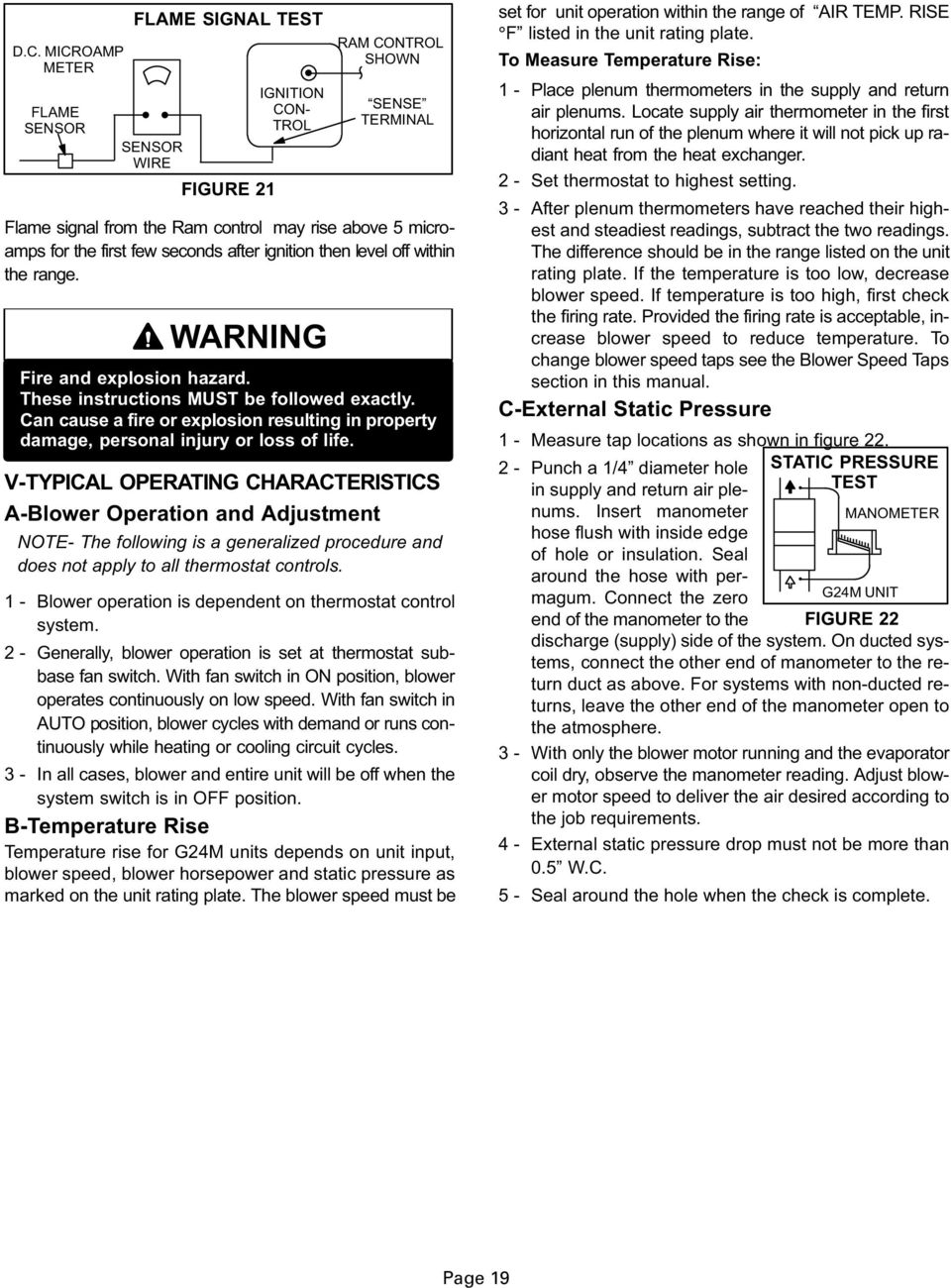
11 4-- Ram Control (A3) Early Model G24M Units The furnace control combines burner ignition functions with blower control functions. Early model G24M units utilize a furnace control manufactured by RAM Electronics Corporation. The RAM board is a printed circuit board which controls the blower, gas valve, combustion air blower and ignition spark. It also monitors the flame, limit and gas valve operation. The control has a non--adjustable, factory preset on fan timing (45 seconds). Fan off timings are adjustable. The board utilizes both 120 and 24VAC. See figure 9. The board is also equipped with a diagnostic LED for use when troubleshooting the unit. When the furnace is idle (blower off and no heating or cooling demand), the diagnostic LED flashes at a slow steady rate. On a call for heat, the diagnostic LED begins flashing at a fast rate and the combustion air blower is energized. The LED flashes different codes to indicate problem conditions. The diagnostic LED lights red (not flashing) to indicate control board failure. Table 7 shows how to interpret the other LED modes. Pre-Purge On a call for heat, the combustion air blower begins operating. If the combustion air prove switch closes, the combustion air blower continues to operate for 45 seconds (pre-purge) before allowing ignition. Prepurge allows the heat exchanger to be cleared of combustion products and to introduce fresh air for combustion. If the combustion air prove switch does not close, the combustion air blower continues to run indefinitely (until the prove switch closes). Post-Purge After a demand, the combustion air blower continues to operate for 5 seconds (post-purge) before stopping. Post-purge allows the heat exchanger to be cleared of combustion products. Ignition Control The ignition control is a direct spark ignition control module integral to the furnace control. See figure 9. When there is a call for heat, the control delays ignition until combustion air blower operation has been proved and pre-purge period has elapsed. It then opens the gas valve and generates a spark to ignite the burners. Trial for ignition lasts for 7 seconds. At the same time, the control begins monitoring the flame sensor. If the flame current is too weak (less than 1 microamp) or if the burners do not ignite (within the 7 second ignition trial), the control will shut off the spark ignitor and the combustion air blower and de-energize the gas valve. Flame current should be between 1 and 5 microamps to keep the gas valve open. See figure 21. The control will attempt to ignite the burners up to two more times. Each time the control restarts the ignition sequence, it begins with a 45 second pre-purge. If flame is not sensed after the third trial, the control locks out. Lockout means that the control shuts off the gas valve, spark and combustion air blower for 60 minutes. At the end of 60 minutes the control completely resets and will attempt ignition up to three times. The control can be manually reset before the end of 60 minutes by momentarily turning off power to the unit. DANGER Shock hazard. Spark related components contain high voltage. Disconnect power before servicing. Control is not field repairable. If control is inoperable, simply replace entire control. Can cause injury or death. Unsafe operation will result if repair is attempted. Page 11
. Fan off timings are adjustable. The board utilizes both 120 and 24VAC. See figure 9.")
12 SPARK OUTPUT EARLY MODEL G24M FURNACE CONTROL (A3) 24VAC VOLT TERMINAL CONNECTIONS LINE VOLTAGE TERMINAL CONNECTIONS See Table 6 for Terminal Functions PLUG P20 FAN-OFF TIMING SWITCHES DIAGSTIC LED THERMOSTAT CONNECTIONS TABLE 5 Furnace Control A3 Limit Response During Operation Condition Loss of Flame Sensed Before End of 45 second Blower On Delay (3 or Fewer Trials for Ignition) Loss of Flame Sensed After 45 second Blower On Delay (3 or Fewer Trials for Ignition) Loss of Flame Sensed (More Than 3 Trials for Ignition) Flame Sensed Without Demand Primary or Secondary Limit Open Rollout Switch Open Combustion Air Prove Switch Open Combustion Air Blower On On Response Gas Valve On (Spark Starts Within 0.8 seconds) Off Then On With Spark After Pre- Purge Supply Air Blower On On Diagnostic LED Fast Flash Fast Flash Off Off Off 2 Flashes On Off On 5 Flashes On Off On 4 Flashes On Off On 4 Flashes On Off On 3 Flashes FIGURE 9 When flame is sensed, the indoor blower starts after a 45 second delay. Gas valve remains open and blower continues to run until demand stops, flame sensor senses loss of flame, a limit opens or the prove switch opens. If any of these events occur during a thermostat demand, the gas valve closes and the diagnostic LED registers the error condition (table 5). Blower Control and Timings DANGER Electrical Shock Hazard. This control contains field adjustable switches and also contains line voltage. Make sure power is disconnected before making any field adjustments or performing any service procedure. TE If fan off time is set too low, residual heat in heat exchanger may cause primary limit S10 to trip resulting in frequent cycling of blower. If this occurs, adjust blower to longer time setting. Fan ON timing (time that the burners operate before the supply air blower starts) is fixed at 45 seconds and cannot be adjusted. Fan OFF timings (time that the blower operates after a heating or cooling demand has been satisfied) are determined by the arrangement of switches on the furnace control board. See figure 9. To adjust fan off timings, gently reposition the switches to a new timing Page 12

13 position. Figure 10 shows the various fan off timings and how switches should be positioned. Unit is shipped with a factory fan off setting of 180 seconds. Fan off time will affect comfort and efficiency and is adjustable to satisfy individual applications. The fan off timing is initiated after a heating or cooling demand but not after a blower demand (that is, when indoor thermostat switch is changed from ON to AUTO and heating/cooling demand is not present, the blower stops immediately). TABLE 6 FURNACE CONTROL A3 TERMINAL DESIGNATIONS Terminal Type Function 24VAC HOT 1/4 Spade 24VAC In From Transformer GND 1/4 Spade To Cabinet Ground Y Screw Strip Cooling Demand G Screw Strip Blower Demand R Screw Strip 24VAC to Thermostat W Screw Strip Heating Demand C Screw Strip 24VAC Common 120VAC HOT 1/4 Spade Line Voltage In 120VAC RTN 1/4 Spade Line Voltage Neutral 120VAC TX 1/4 Spade Line Voltage Out To Transformer CMB J20/P20 Pin 1 Switched 120VAC to Combustion Air Blower CMB RTN J20/P20 Pin 2 120VAC Common Combustion Air Blower ACB HEAT ACB LOW ACB COOL 1/4 Spade 1/4 Spade 1/4 Spade Switched 120VAC to Blower Heating Tap 120VAC Output to Supply Air Blower for Continuous Operation During No Demand Switched 120VAC to Blower Cooling Tap VLV HOT J20/P20 Pin 13 24VAC to Gas Valve VLV RTN J20/P20 Pin 9 24VAC Common From Gas Valve PSW IN HIL IN HIL OUT J20/P20 Pin 10 J20/P20 Pin 11 J20/P20 Pin 14 24VAC In From Pressure Switch Switch Open: Prohibits Ignition Switch Closed: Allows Ignition 24VAC In From Limits Limit Open: Closes Gas Valve Limits Closed: Allows Ignition 24VAC to Limit Train and Pressure Switch RO OUT J20/P20 Pin 7 24VAC Out To Rollout Switches RO IN J20/P20 Pin 15 24VAC In From Rollout Switches SPARK ELECTRODE Male Spark Plug Type High Voltage Out To Spark Electrode FS J20/P20 Pin 12 Flame Microamp Sensing Diagnostic LED FAN-OFF TIME ADJUSTMENT SWITCHES LOCATED ON FURNACE CONTROL (A3) FIGURE 10 Fan-Off Timings Switch 1 2 Off Off Off On On Off On On Timing Seconds The furnace control is equipped with a diagnostic LED used for troubleshooting the unit and the control. LED functions are shown in table 7. TABLE 7 Furnace Control A3 Diagnostic LED LED State Meaning Remedy Steady On Control Failure Replace Control Slow Flash Fast Flash Two Flashes Three Flashes Four Flashes Five Flashes Normal Operation and No Call For Heat Normal Operation with Call For Heat Control Lockout Pressure Switch Open Open Limit Flame Sensed and Gas Valve Not Energized. B--Blower Motors and Capacitors Failed to Sense or Sustain Flame. Check Gas Valve, Burners, Spark Electrode and Wire, Flame Sensor. Replace Control If All OK. Failed to Prove Combustion Blower Operation or Blocked Vent. Repair or Replace as Necessary. Check Primary Limit, Rollout Switches and Secondary Limits. Find source of Overtemperature. If all OK, Reset or Replace Limits as Necessary. Check Gas Valve. If OK, Check Flame Sensor. All G24M units use direct drive blower motors. All motors used are 120V permanent split capacitor motors to ensure maximum efficiency. See table8 for ratings. TABLE 8 G24M BLOWER RATINGS 120V 1PH BLOWER MOTOR HP CAP G24MQ2 G24MQ3 G24MQ3/4 G24MQ4 G24MQ4/5 G24MQ5/6 FIGURE 11 1/4 5MFD 370V 1/3 1/2 5MFD 370V 7.5MFD 370V 1/2 7.5MFD 370V 3/4 40MFD 370V 3/4 40MFD 370V SUPPLY AIR BLOWER AND SECONDARY LIMITS MOTOR CAPACITOR SECONDARY LIMITS (S21) Top Back Left Right Front Bottom BLOWER MOTOR To Remove Blower From Unit: Remove Bolts and Wiring Jackplugs. Then Slide Out Front of Unit. Page 13
.")
14 C--Combustion Air Blower (B6) All G24M units use a combustion air blower to move air through the burners and heat exchanger during heating operation. Some early model G24M units are equipped with a blower that uses a PSC (Permanent Split Capacitor) 120VAC motor. PSC motors use run capacitors. Other early and late model G24M units are equipped with a blower that uses a shaded pole 120V motor. The motor operates during all heating operation and is controlled by furnace control A3. For G24M units equipped with the Ram ignition system, the blower will operate for 45 seconds before burner ignition (pre-purge) and for 5 seconds after the gas valve closes (post-purge). For G24M units equipped with the SureLight ignition system, the blower will operate for 15 seconds before burner ignition (pre purge) and for 5 seconds after the the gas valve closes (post purge). A pressure switch connected to the combustion air blower housing is used to prove combustion air blower operation. The switch monitors air pressure in the blower housing. During normal operation, the pressure in the housing is negative. If pressure becomes less negative (signifying an obstruction) the pressure switch opens. When the pressure switch opens, the furnace control (A3) immediately closes the gas valve to prevent burner operation. D--Flame Rollout Switches (S47) Flame rollout switch is a high temperature limit located on top of the burner box. Each furnace is equipped with two identical switches. One switch is located over the leftmost burner and the other switch is located over the rightmost burner. The limit is a N.C. SPST manual-reset limit connected in series with the ignition control A3. When S47 senses rollout, the ignition control immediately stops ignition and closes the gas valve. If unit is running and flame rollout is detected, the gas valve will close and ignition control will be disabled. Rollout can be caused by a blocked flue or lack of combustion air. The switch is factory set and cannot be adjusted. The setpoint will be printed on the side of the limit. The switch can be manually reset. To manually reset a tripped switch, push the reset button located on the control. ROLLOUT SWITCH (S47) FIGURE 12 MANUAL RESET BUTTON E--Primary Limit Control (S10) LIMIT CONTROL FOR G24M SERIES UNITS THIS TYPE AUTO-RESET LIMIT IS USED FOR THE PRIMARY LIMIT (S10) AND RIGHT SECONDARY LIMIT (S21) (see FIGURE 11) FIGURE 13 The primary limit (S10) on G24M units is located in the middle of the heating vestibule panel. When excess heat is sensed in the heat exchanger, the limit will open. If the limit is tripped, the furnace control energizes the supply air blower and closes the gas valve. The limit automatically resets when unit temperature returns to normal. The switch is factory set and cannot be adjusted. The switch may have different setpoints for each unit model number. However, the setpoint will be printed on the side of the limit. F--Secondary Limit Controls (S21) The secondary limit (S21) on G24M units is located in the blower compartment in the back side of the blower housing. When excess heat is sensed in the blower compartment, the limit will open. If the limit is tripped, the furnace control energizes the supply air blower and closes the gas valve. The limit automatically resets when unit temperature returns to normal. The switch is factory set and cannot be adjusted. Two limits are supplied in each furnace and each limit is a different style (figures 13 and 14). The setpoint will be printed on the side of the limit. If stick limit (figure 14) suffers from nuisance trips anf the furnace is in the horizontal position, replace with limit kit no. 50L98. INSULATING COVER LIMIT SECONDARY LIMIT CONTROL (S21) FOR G24M SERIES UNITS SPADE CONNECTORS THIS TYPE AUTO-RESET LIMIT IS USED FOR THE LEFT SECONDARY LIMIT (S21) (see FIGURE 11) INSULATING COVER (s) FIGURE 14 G--Spark Electrode and Flame Sensor Early Model G24M Units Figure 15 shows the arrangement of flame sensor, spark electrode and burners. The ignition control uses direct spark to ignite the rightmost burner and the burners cross-light to the left. The flame sensor uses flame rectification to sense combustion. A flame retention ring in the end of each burner is used to maintain correct flame length and shape and to keep the flame from lifting off the burner head. Figure 16 shows the gap between tip of the electrodes and the burner surface. LIMIT Page 14
 and for 5 seconds after the gas valve closes (post-purge).")
15 TYPICAL BURNER/ELECTRODE ORIENTATION view looking at flame end of burners 1/8 (+1/64 ) UPPER BURNER BURNER MANIFOLD ORIFICE MOUNTING RAIL Top Right Left Bottom GROUND SPARK ELECTRODE FLAME RETENTION RING FIGURE 15 LOWER BURNER MOUNTING RAIL FLAME SENSOR (SOME UNITS MAY HAVE SENSOR LOCATED IN MIDDLE OF BURNER) SPARK ELECTRODE TO BURNER GAP 1/4 in. 7 mm p 1/32 in mm BURNER 3/16 in. 4.7 mm 11/16 in. 18 mm p 1/32 in mm TYPICAL ACCESS TO REGULATOR FOR ADJUSTMENT AND L.P. CHANGEOVER (Honeywell VR8205 series gas valve shown) 287/(7 35(6685( 7$3,1/(7 35(6685( 7$3 2)) 21 FLAME SENSOR SIDE VIEW FIGURE 16 END VIEW H--Gas Valve The G24M uses a gas valve manufactured by Honeywell (figure 17) or White Rodgers (figure 18). The valve is internally redundant to assure safety shut--off. If the gas valve must be replaced, the same type valve must be used. 24VAC terminals and gas control knob are located on top of the valve. All terminals on the gas valve are connected to wires from the electronic ignition control. 24V applied to the terminals energizes the valve. Inlet and outlet pressure taps are located on the valve. A regulator adjustment screw is located on the valve. Refer to figure 17 or 18 for location of valve features. An LPG changeover kit is available from Lennox. The kit includes burner orifices and a regulator conversion kit. I--Combustion Air Blower Prove (Pressure) Switch (S64) G24M series units are equipped with a combustion air prove switch located on the vestibule panel. The switch is connected to the combustion air blower housing by means of a flexible silicone hose. It monitors air pressure in the combustion air blower housing. *$6 9$/9( 6+2:1,1 2)) 326,7,21 35(6685( 5(*8/$725 $'-867,1* 6&5(: :KLWH GAS VALVE KB SHOWN IN OFF POSITION GAS INLET 35(6685( 7$3 FIGURE 17 WHITE RODGERS 36E GAS VALVE FIGURE 18 &$3 6&5(: %ODFN 635,1* 7DSHUHG (QG 'RZQ 5HG,1/(7 35(6685( 7$3 *$6,1/(7 REGULATOR COVER SCREW 35(6685( 7$3 Page 15

16 The switch is a single-pole single-throw pressure switch electrically connected to the furnace control. The purpose of the switch is to prevent burner operation if the combustion air blower is not operating. PROVE SWITCH PROVE SWITCH COMBUSTION AIR BLOWER PROVE SWITCH Normally Open Closes on Negative Pressure FIGURE 19 Sensing Tube Attaches to Top Side Of Blower Top Back Right Left Front Bottom On start-up, the switch senses that the combustion air blower is operating. It closes a circuit to the furnace control when pressure inside the combustion air blower increases above switch setting (negative) w.c. The pressure sensed by the switch is relative to atmospheric pressure. If the flue becomes obstructed during operation, the switch senses a loss of negative pressure (pressure becomes more equal with atmospheric pressure) and opens the circuit to the furnace control and gas valve. The switch trip pressure is different depending on unit model number. The trip pressure is printed on the side of the limit. The switch is factory set and is not field adjustable. It is a safety shut-down control in the furnace and must not be bypassed for any reason. II--PLACEMENT AND INSTALLATION Make sure unit is installed in accordance with installation instructions and applicable codes. III--START-UP A--Preliminary and Seasonal Checks 1 -- Inspect electrical wiring, both field and factory installed for loose connections. Tighten as required Check voltage at disconnect switch. Voltage must be within range listed on the nameplate. If not, consult the power company and have voltage condition corrected before starting unit. B--Heating Start-Up 1 -- Set thermostat to OFF position. Close manual knob on gas valve Wait 5 minutes Open manual knob on gas valve, replace burner access door and turn on unit electrical supply. WARNING Shock and burn hazard. G24M units are equipped with either a direct spark or hot surface ignition system. Do not attempt to light manually Set fan switch to AUTO or ON and move system selection switch to HEAT. Adjust thermostat to a setting above room temperature If unit does not light the first time, the SureLight control will attempt four more ignitions, the Ram control will attempt two more ignitions before locking out If lockout occurs, repeat steps 1, 2, 3 and 4. C--Safety or Emergency Shutdown Turn off unit power. Close manual and main gas valves. IMPORTANT In case emergency shutdown is required, turn off the main shut-off valve and disconnect the main power to unit. These controls should be properly labeled by the installer. D--Extended Period Shutdown Turn off thermostat or set to UCCUPIED mode. Close all gas valves (both internal and external to unit) to guarantee no gas leak into combustion chamber. Turn off power to unit. All access panels, covers and vent caps must be in place and secured. Page 16

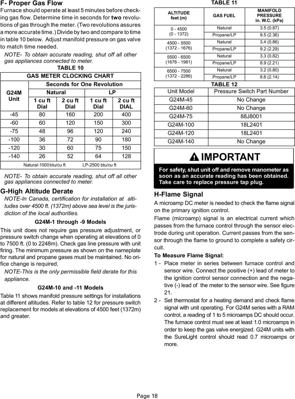
17 IV--HEATING SYSTEM SERVICE CHECKS A--A.G.A./C.G.A. Certification All units are A.G.A. design certified without modifications. Refer to the G24M Operation and Installation Instruction Manual for Information. B--Gas Piping Gas supply piping should not allow more than 0.5 W.C. drop in pressure between gas meter and unit. Supply gas pipe must not be smaller than unit gas connection. Compounds used on gas piping threaded joints should be resistant to action of liquefied petroleum gases. C--Testing Gas Piping When pressure testing gas lines, the gas valve must be disconnected and isolated. Gas valves can be damaged if subjected to more than 0.5psig (14 W.C.). See figure 20. If the pressure is equal to or less than 0.5psig (14 W.C.), use the manual shut--off valve before pressure testing to isolate furnace from gas supply. GAS PIPING TEST PROCEDURE MANUAL MAIN SHUT--OFF VALVE WILL T HOLD TEST PRESSURE IN EXCESS OF 0.5 PSIG (14 W.C.) GAS VALVE CAP FIELD PROVIDED LINE PRESSURE TAP FIGURE 20 When checking piping connections for gas leaks, use preferred means. Kitchen detergents can cause harmful corrosion on various metals used in gas piping. Use of a specialty Gas Leak Detector is strongly recommended. It is available through Lennox under part number 31B2001. See Corp L10, for further details. Do not use matches, candles, flame or any other source of ignition to check for gas leaks. D--Testing Gas Supply Pressure When testing supply gas pressure, connect test gauge to inlet pressure tap (field provided). See figure 20. Check gas line pressure with unit firing at maximum rate. Low pressure may result in erratic operation or underfire. High pressure can result in permanent damage to gas valve or overfire. For natural gas units, operating pressure at unit gas connection must be between 5.0 W.C. and 13.0 W.C. For L.P. gas units, operating pressure at unit gas connection must be between 10.0 W.C. and 13.0 W.C. On multiple unit installations, each unit should be checked separately, with and without other units operating. Supply pressure must fall within range listed in previous paragraph. E--Check Manifold Pressure After line pressure has been checked and adjusted, check manifold pressure. Move pressure gauge to outlet pressure tap located on unit gas valve (GV1). Checks of manifold pressure are made as verification of proper regulator adjustment. Manifold pressure for the G24M can be measured at any time the gas valve is open and is supplying gas to the unit. Normal manifold pressure for natural gas units is 3.5 in. w.c. For LP/propane gas the correct manifold pressure is 9.5 in. w.c. IMPORTANT For safety, connect a shut-off valve between the manometer and the gas tap to permit shut off of gas pressure to the manometer. TABLE 9 GAS VALVE REGULATION Unit (Fuel) Operating Pressure (outlet) in. W.C. Natural L.P The gas valve is factory set and should not require adjustment. All gas valves are factory regulated. See table 9. Manifold Adjustment Procedure: 1 -- Connect a test gauge to outlet pressure tap on gas valve. Start unit and allow 5 minutes for unit to reach steady state While waiting for the unit to stabilize, notice the flame. Flame should be stable and should not lift from burner. Natural gas should burn blue. L.P. gas should burn mostly blue with some orange streaks After allowing unit to stabilize for 5 minutes, record manifold pressure and compare to values given in table 9. TE--Shut unit off and remove manometer as soon as an accurate reading has been obtained. Take care to replace pressure tap plug. Page 17
. See figure 20.")
18
19
20
21 To clean burners: 1 -- Turn off both electrical and gas power supplies to furnace Disconnect gas supply piping and remove gas manifold Disconnect ignitor and flame sensor leads Remove burner tray and burners Clean burner retention ring with wire brush Use test tube brush to clean inside of each burner Replace burners and burner tray, making sure burners are properly seated in slots on tray and orifice in manifold Reinstall burner box and gas supply piping. Reconnect ignitor and flame sense leads Carefully check all piping connections (factory and field) for gas leaks. Use a leak detecting solution or other preferred means Restore electrical power and gas supply. Follow lighting instructions on front of unit. CAUTION Potential for gas leaks, fire or explosion. Some soaps used for leak detection are corrosive to certain metals. Carefully clean piping thoroughly after leak detection has been completed. Can cause damage to piping resulting in gas leaks, fire or explosion. C--Supply Air Blower 1 -- Check and clean blower wheel Motors used on the Lennox G24M series units are permanently lubricated and need no further lubrication. D--Flue and Chimney Flue must conform to all AGA/GAMA venting requirements. Flue pipe deteriorates from the inside out and must be disconnected in order to check thoroughly. Check flue pipe, chimney and all connections for tightness and to make sure there is no blockage or leaks. E--Electrical 1 -- Check all wiring for loose connections Check for correct voltage Check amp--draw on blower motor. HEAT EXCHANGER REMOVAL (unit shown in horizontal position) REMOVE SCREWS (4) Left Bottom Back Top Front Right SLIDE ENTIRE ASSEMBLY OUT OF CABINET FIGURE 24 Page 21
22 VII--WIRING, OPERATION SEQUENCE &TROUBLESHOOTING A--Field Wiring, Thermostat Connections ),(/',167$//(' &/$66,, 9 ),(/',167$//(' /,1( 92/7$*( 7<3,&$/ *0 ),(/' :,5,1* ',$*5$0 35(6685( 6:,7&+ 35,0$5< /,0,7 &20%867,21 $,5 %/2:(5 )851,6+(' %<,167$//(5 / 1 *1' 7+(50267$7 : 5 < * )/$0( 52//287 6:,7&+(6 75$16)250(5 *$6 9$/9( 6(&21'$5< /,0,76 %/$&. :+,7( 72 &2035(6625 &217$&725 < * : 5 & 685(/,*+7 &21752/ '225,17(5/2&. 6:,7&+ ),*85( G24M and CONDENSING UNIT THERMOSTAT DESIGNATIONS (Refer to specific thermostat and outdoor unit.) Thermostat G24M Furnace Condensing Unit Y COOLING Y COMPRESSOR HS UNIT COMPRESSOR G INDOOR BLOWER G W HEAT W R C POWER COMMON R C COMMON HS UNIT COMMON ),*85( 3DJH
23 B--Early Model G24M Series With Ram Ignition Control 1--When disconnect is closed, 120V is routed through door interlock switch (S51) to feed the line voltage side of the furnace control (A3) and transformer T1 primary. Door interlock switch must be closed for A3 and T1 to receive voltage T1 supplies 24VAC to terminal 24VAC on A3. In turn, terminal R of A3 supplies 24VAC to terminal RC of the indoor thermostat (not shown) When there is a call for heat, W1 of the thermostat energizes W of the furnace control with 24VAC CMB BLWR of the blower control energizes the combustion air blower (B6). When the combustion air blower nears full speed, combustion air prove switch (S18) closes When S18 closes, assuming the flame rollout switch (S47), primary limit (S10) and secondary limits (S21) are closed, the furnace control begins a 45 second time-delay (pre-purge) At the end of the pre-purge cycle, the furnace control simultaneously opens the gas valve and sends high voltage to the spark electrode When flame is sensed, the furnace control begins a 45 second delay before energizing the indoor blower When heat demand is satisfied, W1 of the thermostat de-energizes W of the furnace control and the furnace control immediately de-energizes the gas valve. The combustion air blower runs for 5 seconds (post-purge) before being de-energized. Also, the indoor blower runs for a designated period ( seconds) as set by switches on furnace control. 3DJH
24 C--Ram Ignition Control Troubleshooting Guide RAM CONTROL HEATING TROUBLE SHOOTING SEQUENCE RMAL HEATING MODE ABRMAL HEATING MODE LED: SLOW FLASH RATE THERMOSTAT CALLS FOR HEAT LED: FAST FLASH RATE FLAME OFF? CONTROL SELF--CHECK OKAY? LOCKOUT: MAIN VALVE OFF COMB. AIR AND SYSTEM FANS ON RESET THERMOSTAT LED: 5 flash if flame sensed with valve off LED: Steady on if control board failure HI LIMIT SWITCH CLOSED? PRESSURE SWITCH OPEN? COMBUSTION AIR BLOWER ON? CHECK TO SEE IF MAIN VALVE IS OFF. SEQUENCE HOLDS UNTIL HI LIMIT CLOSES. LED: 4 flashes. CHECK TO SEE IF MAIN VALVE IS OFF. SEQUENCE HOLDS UNTIL PRES. SWITCH OPENS. LED: 3 flashes. PRESSURE SWITCH CLOSED? CHECK TO SEE IF MAIN VALVE IS OFF. SEQUENCE HOLDS UNTIL PRES. SWITCH CLOSES. LED: Fast flash rate. PREPURGE (45 seconds) IGNITION TRIAL (7 seconds) ---- START IGNITION SPARK, OPEN MAIN GAS VALVE. INCREMENT TRIAL REGISTER. HAS FLAME BEEN REGISTERED WITHIN 7 SECONDS? MAIN VALVE AND SPARK ARE OFF. INCREMENT TRIAL REGISTER THREE TRIALS COMPLETED? SYSTEM FAN ON. (Fixed 45--second delay) IGNITION RESET PERIOD COMBUSTION & SYSTEM FANS OFF. IS 60 MIN. RESET PERIOD COMPLETE? LED: Fast flash rate. FLAME SENSE OKAY? FLAME CONTINUOUSLY CHECKED? MAIN VALVE AND SPARK OFF. START IGNITION SPARK (IN 0.8 SEC. MAXIMUM). HAS FLAME BEEN DETECTED WITHIN 7 SEC.? ROLLOUT SWITCHES CLOSED HI LIMIT SWITCH CLOSED? LOCKOUT. MAIN VALVE OFF. COMBUSTION AND SYSTEM FANS ON. RESET OR REPLACE ROLLOUT SWITCH. LED: 4 flashes. PRESSURE SWITCH CLOSED? THERMOSTAT OPENS MAIN VALVE OFF. COMBUSTION & SYSTEM FANS ON. SEQUENCE HOLDS UNTIL SWITCH CLOSES. LED: 4 flashes for hi limit. LED: 3 flashes for pressure switch. LED: SLOW FLASH RATE SWITCH CLOSED COMB. AIR BLOWER OFF (5 sec. delay) COMBUSTION FAN ON. SYSTEM FAN OFF. (AFTER DELAY TO OFF INTERVAL COMPLETED.) FAN OFF (After selected 90, 120, 180, or 240 delay)? LED: Fast flash rate. 3DJH
25 RAM CONTROL COOLING TROUBLE SHOOTING SEQUENCE LED: Slow flash rate. REMAINS UNCHANGED THROUGHOUT COOLING CYCLE. THERMOSTAT CALLS FOR COOLING. COMPRESSOR CONTACTOR AND SYSTEM FAN ENERGIZED AT COOLING SPEED AFTER 1 SECOND DELAY. ACC TERMINAL ENERGIZED. THERMOSTAT OPENS. COMPRESSOR OFF. SYSTEM FAN AND ACC TERMINAL OFF AFTER COMPLETING SELECTED DELAY INTERVAL (At dip switches). MANUAL FAN TROUBLESHOOTING SEQUENCE LED: Slow flash rate. REMAINS UNCHANGED THROUGHOUT SEQUENCE. MANUAL FAN SELECTION MADE AT THERMOSTAT. CONTROL ENERGIZES SYSTEM FAN AT CONTINUOUS SPEED. ACC TERMINAL ENERGIZED. THERMOSTAT CALLS FOR HEAT. THERMOSTAT CALLS FOR COOLING. SYSTEM FAN SWITCHES TO HEATING SPEED AFTER SELECTED DELAY. ACC TERM. REMAINS ENERGIZED. SYSTEM FAN SWITCHED TO COOLING SPEED. ACC TERMINAL REMAINS ENERGIZED. THERMOSTAT OPENS. THERMOSTAT OPENS. SYSTEM FAN SWITCHED OFF AFTER DELAY. ACC TERMINAL DE--ENERGIZED. SYSTEM FAN SWITCHES TO CONTINUOUS SPEED AND ENERGIZES ACC TERMINAL. BOTH REMAIN ON UNTIL MANUAL FAN IS SWITCHED OFF AT THERMOSTAT. SLOW FLASH FAST FLASH 2 FLASH 3 FLASH 4 FLASH 5 FLASH STEADY ON. LED CODES RMAL OPERATION. CALL FOR HEAT. RMAL OPERATION. CALL FOR HEAT. SYSTEM LOCKOUT. FAILURE TO DETECT OR SUSTAIN FLAME. PRESSURE SWITCH OPEN OR CLOSED. HIGH LIMIT OR ROLLOUT SWITCH OPEN. FLAME SENSED AND GAS VALVE T ENERGIZED. CONTROL BOARD FAILURE. 3DJH
26 D-Late Model G24M Series With SureLight Ignition Control TYPICAL G24M DIAGRAM (-11 MODEL SHOWN) 1 - When there is a call for heat, W1 of the thermostat energizes W of the furnace control with 24VAC. 2 - S10 primary limit switch and S47 rollout switch are closed. Call for heat can continue. 3 - SureLight control energizes combustion air blower B6. Combustion air blower runs until S18 combustion air prove switch closes (switch must close within 2-1/2 minutes or control goes into 5 minute Watchguard Pressure Switch delay). Once S18 closes, a 15-second pre-purge follows. 4 - SureLight control energizes ignitor. A 20-second warm-up period begins. 5 - Gas valve opens for a 4-second trial for ignition. Ignitor stays energized the first second of trial. (Board 97L48 only: ignitor energized during trial or until flame is sensed. 6 - Flame is sensed, gas valve remains open for the heat call. 7 - After 45-second delay, SureLight control energizes indoor blower B Whenheatdemandis satisfied,w1 ofthe indoorthermostat de-energizes W of the SureLight control which de-energizes the gas valve. Combustion air blower B6 continues a 5-second post-purge period, and indoor blower B3 completes a selected OFF time delay. Page 26
27 SURELIGHT CONTROL HEATING SEQUENCE OF OPERATION RMAL HEATING MODE ABRMAL HEATING MODE POWER ON CONTROL SELF--CHECK OKAY? COMBUSTION AIR BLOWER ON FOR 1 SECOND. TURN INDUCER ON FOR 1 SECOND. IS POLARITY REVERSED? GAS VALVE OFF. COMBUSTION AIR BLOWER ON. INDOOR BLOWER ON. LED #1 ALTERNATING FAST FLASH LED#2 ALTERNATING FAST FLASH CHECK FOR BROKEN IGNITOR OR OPEN IGNITOR CIRCUIT GAS VALVE OFF. COMBUSTION AIR BLOWER OFF. INDOOR BLOWER DELAY OFF. LED #1 ON LED #2 ON (RESET CONTROL BY TURNING MAIN POWER OFF.) SIGNAL IMPROPER GROUND AT LED. SIGNAL HOLDS UNTIL UNIT IS PROPERLY GROUNDED. IS THERE PROPER GROUND? ROLLOUT SWITCH CLOSED? BURNER OFF? (CONTINUOUS FLAME CHECK) IS VOLTAGE ABOVE 75 VOLTS? POLARITY REVERSED. LED # FAST FLASH LED # SLOW FLASH LOW VOLTAGE SIGNAL AT LED HOLDS UNTIL VOLTAGE RISES ABOVE 75 VOLTS. GAS VALVE OFF. COMBUSTION AIR BLOWER OFF. INDOOR BLOWER OFF WITH DELAY. LED # ON. LED # SLOW FLASH. SEQUENCE HOLDS UNTIL ROLLOUT SWITCH CLOSES. RMAL OPERATION: LED # SLOW FLASH LED # SLOW FLASH THERMOSTAT CALLS FOR HEAT: LED # FAST FLASH LED # FAST FLASH IS COMBUSTION AIR PRESSURE SWITCH OPEN? IS COMBUSTION AIR BLOWER ENERGIZED? (HTG ACC TERMINAL IS ENERGIZED WITH C.A.B.) GAS VALVE OFF. COMBUSTION AIR BLOWER ON. INDOOR BLOWER ON HEATING SPEED. LED # SLOW FLASH LED # OFF GAS VALVE OFF. COMBUSTION AIR BLOWER OFF. INDOOR BLOWER OFF WITH DELAY. LED #1 OFF LED #2 SLOW FLASH (Sequence holds until pressure switch closes or thermostat resets control.) HAS COMBUSTION AIR PRESSURE SWITCH CLOSED IN 2.5 MINUTES? 15-SECOND COMBUSTION AIR BLOWER PREPURGE INITIATED BY CLOSED PRESSURE SWITCH. CONTINUED NEXT PAGE PRESSURE SWITCH IS IN WATCHGUARD MODE. GAS VALVE OFF. COMBUSTION AIR BLOWER OFF. INDOOR BLOWER OFF WITH DELAY. LED # OFF. LED # SLOW FLASH. IS 5-MINUTE RESET PERIOD COMPLETE? 3DJH
G26 Corp. 9721-L11 Revised 07-2001 LENNOXOEMPARTS.COM. Service Literature G26 SERIES UNITS
 Service Literature G26 SERIES UNITS G26 series units are high-efficiency upflow gas furnaces manufactured with DuralokPlust aluminized steel clamshell-type heat exchangers. G26 units are available in heating
80UHG. Service Literature
 Service Literature Corp. 9728 L12 Revised 01 2002 80UHG 80UHG series units are mid efficiency gas furnaces used for upflow or horizontal applications only, manufactured with tubular heat exchangers formed
Commercial Gas Furnace Upflow
 Commercial Gas Furnace Upflow Model G24-200 80% A.F.U.E. 200,000 Btuh Input Heating Cap. 7.5 or 10 Tons Nominal Add-On Cooling GUK FEATURES Certified by A.G.A./C.G.A. Laboratories. Heavy gauge painted
Cooling Capacity CFM range @.5 in. w.c. (125 Pa)
") N8MXL Product Specifications 80% ECM Single Stage Heating Furnace EASIER TO SELL 80% AFUE Flame roll out sensors standard Category I venting Blocked vent switch 24 VAC humidifier terminal Electronic air
N8MXL Product Specifications 80% ECM Single Stage Heating Furnace EASIER TO SELL 80% AFUE Flame roll out sensors standard Category I venting Blocked vent switch 24 VAC humidifier terminal Electronic air
G670 Intermittent Pilot Ignition Controls
 Installation Sheets Manual 121 Gas Combustion Combination Controls and Systems Section G Technical Bulletin Issue Date 0300 Intermittent Pilot Ignition Controls Figure 1: Intermittent Pilot Ignition Control
SL280UHV SERIES GAS FURNACE WARNING
 2010 Lennox Industries Inc. Dallas, Texas, USA 506677 01 11/2010 Supersedes 506409 01 SL280UHV SERIES GAS FURNACE Litho U.S.A. FIRE OR EXPLOSION HAZARD. Failure to follow safety warnings exactly could
Cooling Capacity CFM range @.5 in. w.c. (125 Pa)
") 96% AFUE, Single Stage, ECM Gas Furnace EASIER TO SELL 96% AFUE, all models all positions Xtra SEER ECM blower motor Supports two stage cooling units Dehumidification feature in cooling California NOx
96% AFUE, Single Stage, ECM Gas Furnace EASIER TO SELL 96% AFUE, all models all positions Xtra SEER ECM blower motor Supports two stage cooling units Dehumidification feature in cooling California NOx
Cooling Capacity CFM range @.5 in. w.c. (125 Pa)
") 96% AFUE, Two Stage ECM Gas Furnace EASIER TO SELL 96% AFUE, all models, all positions Two stage heating operation Xtra SEER ECM blower motor Supports two stage cooling units Dehumidification feature in
96% AFUE, Two Stage ECM Gas Furnace EASIER TO SELL 96% AFUE, all models, all positions Two stage heating operation Xtra SEER ECM blower motor Supports two stage cooling units Dehumidification feature in
USER S, MAINTENANCE and SERVICE INFORMATION MANUAL
 CONTENTS SAFETY INFORMATION................ 2 FOR YOUR SAFETY....................... 2 SYSTEM OPERATION.................. 2 THERMOSTATS........................... 2 INTERMITTENT IGNITION DEVICE...........
Gas Unit Heaters Duct Furnaces Horizontal - 60 HZ Form No. LF24-100-400 (10/2011) LF24 Standard
 LF24 Standard") LF Standard Features Horizontal unit heaters are compact in design and easy to install. Steady State Efficiencies of up to 80.%. Ideal for economical commercial heating systems. Shipped completely assembled
LF Standard Features Horizontal unit heaters are compact in design and easy to install. Steady State Efficiencies of up to 80.%. Ideal for economical commercial heating systems. Shipped completely assembled
Your safety and the safety of others are very important.
 NATURAL GAS TO PROPANE CONVERSION KIT 090 INSTALLATION INSTRUCTIONS FOR ALTITUDES 0 -,00 FT. ONLY PROPANE CONVERSION KIT SAFETY... INSTALLATION REQUIREMENTS... Tools and Parts... LP Gas Requirements...
prestige Condensing Water Boiler SERVICE TECHNICIAN S TROUBLE SHOOTING GUIDE 2008-36 TSG-PRESTIGE Date revised: 12/6/10
 prestige Condensing Water Boiler SERVICE TECHNICIAN S TROUBLE SHOOTING GUIDE Date revised: 12/6/10 2008-36 TSG-PRESTIGE Table of Contents INTRODUCTION Page 1-2 SERVICING TIPS AND INSTRUCTIONS Page 3-4
F9MXE. Product Specifications
 96% AFUE, Single Stage, ECM Gas Furnace EASIER TO SELL 96% AFUE, all models all positions Select models earn the ENERGY STAR (See below, indicated with check mark.) Xtra SEER ECM blower motor Supports
http://waterheatertimer.org/how-to-troubleshoot-gas-water-heater.html
 http://waterheatertimer.org/how-to-troubleshoot-gas-water-heater.html APPLY POWER TO APPLIANCE FIELD WIRING CORRECT? DPLAY ERROR CODE 1 OR 2 Intelli-Vent TM Sequence of Operation REQUEST FOR HEAT PRESENT?
XV80 UPFLOW/HORIZONTAL 2-STAGE, VARIABLE SPEED GAS-FIRED FURNACE
 UPF/HORIZONTAL 2-, VARIABLE SPEED GAS-FIRED FURNACE XV80 MODELS TUD2B060A9V3VB, TUD2B080A9V3VB TUD2C080A9V4VB, TUD2C080B9V4VB TUD2B00A9V3VB, TUD2C00A9V5VB TUD2C00B9V5VB, TUD2DA9V5VB TUD2DB9V5VB, TUD2DA9V5VB
G9MXE. Product Specifications
 Up to 96% AFUE, Single Stage, ECM Gas Furnace EASIER TO SELL Up to 96% AFUE, all models all positions California NOx approved Select models earn the ENERGY STAR (See below, indicated with check mark.)
36G22, 36G23, 36G24 & 36G52 36J22, 36J23, 36J24 & 36J52 DSI and HSI Single Stage Combination Gas Valve
 Operator: Save these instructions for future use! FAILURE TO READ AND FOLLOW ALL INSTRUCTIONS CAREFULLY BEFORE INSTALLING OR OPERATING THIS CONTROL COULD CAUSE PERSONAL INJURY AND/OR PROPERTY DAMAGE. DESCRIPTION
TECHNICAL SERVICE DEPARTMENT Technical Service Bulletin 1-800-432-8373. 2 Inch PowerVent LED Indicator Explanations & Troubleshooting Table
 New Robertshaw control valve was introduced in May 2008 as a replacement part. See last page for troubleshooting this replacement part. All voltage inputs are 120V. All electrical connectors are Molex
M7RL Series TECHNICAL SPECIFICATIONS. FEATURES and BENEFITS. High Efficiency / Direct Vent Condensing Downflow Gas Furnace
 TECHNICAL SPECIFICATIONS M7RL Series High Efficiency / Direct Vent Condensing Downflow Gas Furnace Induced Draft - 9%+ AFUE Input 4,000 thru 7,000 Btuh The high efficiency downflow gas furnace is especially
http://waterheatertimer.org/how-to-troubleshoot-gas-water-heater.html
 http://waterheatertimer.org/how-to-troubleshoot-gas-water-heater.html TECHNICAL SERVICE DEPARTMENT Effective October 2007, we transitioned to the White Rodgers (Intelli-Vent TM )Thermostat Control for
THC 85 INDUSTRIAL / COMMERCIAL SPACE HEATER
 THC 85 INDUSTRIAL / COMMERCIAL SPACE HEATER Certified to / Certifié à CGA 2.14 M2000 Conforms to / Conforme à ANSI std Z83.7 2000 Suitable for indoor or outdoor installation / Unvented / Unattended Type
Fossil fuel heating equipment
 Fossil fuel heating equipment principles and troubleshooting techniques Application Note This application note was written to provide you with an understanding of the basic principles of fossil fuel heating
with MERCURY FREE 1 HP Relays ! WARNING Before using this product read and understand instructions.
 B Installation & Maintenance Instructions MM-414 Series 150E and 157E Low Water Cut-Off/Pump Controllers For Steam Boilers and Other Level Control Applications A Typical Applications: Primary or secondary
TB-A028-06 - A. O. SMITH - FVIR INTELLI-VENT TROUBLESHOOTING CHART # LED STATUS PROBLEM SOLUTION
 1 2 3 4 5 Inadequate or no earth ground sensed by the Intelli-Vent control. Power supply to Intelli-Vent control has reversed polarity. Pressure switch circuit remaining closed for more than 5 seconds
37E73A-903 & 906 INTELLI-VENT
 37E73A-903 & 906 INTELLI-VENT Water Heater Thermostat Control Installation Instructions For Natural Gas Only Operator: Save these instructions for future use FAILURE TO READ AND FOLLOW ALL INSTRUCTIONS
E2 Series Electric Furnaces
 E2 Series Electric Furnaces Service Manual Table of Contents Electrical Requirements... 10 Codes, Specifications Requirements... 10 Connection Supply Service Wires... 10 Furnace Sequence of Operation...
CARING FOR YOUR WATER HEATER
 http://waterheatertimer.org/troubleshoot-rheem-tankless-water-heater.html Water Heater Inspections CARING FOR YOUR WATER HEATER Venting System (Direct Vent Only) The venting system should be inspected
Evaluate, Clean, and Tune Guidance
 Evaluate, Clean, and Tune Guidance The Evaluate, Clean and Tune (ECT) process serves three essential purposes in the Weatherization Assistance Program (WAP). The first is to evaluate the existing system
SIMPLE ELECTRONIC IGNITION WIRE DIAGRAM THERMOSTAT (3) PV PILOT BURNER/IGNITOR - SENSOR Q345A (9) SPARK (4) GND (BURNER) CHASSIS GND
 PV PILOT BURNER/IGNITOR - SENSOR Q345A (9) SPARK (4) GND (BURNER) CHASSIS GND") Honeywell Electronic Ignition Troubleshooting Tech Tip April 2007 The Honeywell S8610H Intermittent Pilot Module provides the ignition sequencing, pilot spark, pilot flame monitoring, Pilot Valve (PV)
Honeywell Electronic Ignition Troubleshooting Tech Tip April 2007 The Honeywell S8610H Intermittent Pilot Module provides the ignition sequencing, pilot spark, pilot flame monitoring, Pilot Valve (PV)
Installation Instructions
 H5HK Series Installation Instructions 3 Phase Electric Heater Kits 7.5 and 0 TON Package A/C Systems Description Installation of 08/40V and 480V H5HK 3 Phase Heater Kits in 7.5 and 0 TON Packaged Air Conditioners.
Thermo Top - Troubleshooting Tree
 Thermo Top - Troubleshooting Tree 07-15-2002 CAUTION Troubleshooting requires comprehensive knowledge about the structure and theory of operation of the Thermo Top heater. Troubleshooting and repairs may
Portable Air Conditioner. OWNER S MANUAL Read these instructions before use. Model: MM14CCS. Voltage rating: 115V~60Hz Power rating : 1400W
 Portable Air Conditioner OWNER S MANUAL Read these instructions before use Model: MM14CCS Customer Support : 1-800-474-2147 Voltage rating: 115V~60Hz Power rating : 1400W For product inquiries or support
GCS16 GCS20 WARNING CAUTION
 Service Literature Corp. 0110 L6 Revised 12 2004 GCS16/GCS20 SERIES UNITS GCS16 GCS20 2 to 5 Ton GCS16/20 series units in the 2 to 5 ton (7.0 to 17.0 kw) cooling size are packaged combination gas heat
XV 95. Upflow/ Horizontal Left, Downflow/ Horizontal Right Variable Speed Two Stage Condensing Gas-Fired Furnace PUB. NO.
 Upflow/ Horizontal Left, Downflow/ Horizontal Right Speed Two Stage Condensing Gas-Fired Furnace XV 95 TUH2B060A9V3VB TUH2B080A9V3VB TUH2B080A9V4VB TUH2C100A9V4VB TUH2C100A9V5VB TUH2D120A9V5VB Direct Vent
Portable Air Conditioner. OWNER S MANUAL Read these instructions before use. Model: MN12CES / MN10CESWW
 Portable Air Conditioner OWNER S MANUAL Read these instructions before use 8 Model: MN12CES / MN10CESWW Voltage rating: 120V~60Hz Power rating : 1100W (MN12CES) Power rating : 900W (MN10CESWW) Customer
TECHNICAL MANUAL GDS8 & GHS8
 TECHNICAL MANUAL AL GDS8 & GHS8 33-3/8" 80% Gas Furnace Units Refer to Service Manual RS6610004 for installation, operation, and troubleshooting information. All safety information must be followed as
Operator: Save these instructions for future use!
 WHITE-RODGERS 36C01 Combination Gas Valves (24 Volt and 120 Volt Models) INSTALLATI INSTRUCTIS FAILURE TO READ AND FOLLOW ALL INSTRUCTIS CAREFULLY BEFORE INSTALLING OR OPERATING THIS CTROL COULD CAUSE
Portable Air Conditioner. OWNER S MANUAL Read these instructions before use. Model: MF08CESWW. Voltage rating: 115V~60Hz Power rating : 800W
 MODE ALARM Portable Air Conditioner OWNER S MANUAL Read these instructions before use 8 Model: MF08CESWW Voltage rating: 115V~60Hz Power rating : 800W Customer Support : 1-800-474-2147 For product inquiries
Service manual. Website: www.andico.com.au CAUTION - BEFORE SERVICING THE UNIT, READ THE SAFETY - PRECAUTIONS IN THIS MANUAL.
 Website: www.andico.com.au Service manual CAUTION - BEFORE SERVICING THE UNIT, READ THE SAFETY - PRECAUTIONS IN THIS MANUAL. - ONLY FOR AUTHORISED SERVICE PERSONNEL. MODELS: MPK1-09CR-QB8 MPK1-12ER-QB6
! WARNING. McDonnell & Miller Installation & Maintenance Instructions MM-217(I) Series 150S and 157S (Snap Switch, All Models except 157S-RB-P)
 Series 150S and 157S (Snap Switch, All Models except 157S-RB-P)") Series 150S and 157S (Snap Switch, All Models except 157S-RB-P) Low Water Cut-Off/Pump Controllers For Steam Boilers and Other Level Control Applications McDonnell & Miller Installation & Maintenance Instructions
Series 150S and 157S (Snap Switch, All Models except 157S-RB-P) Low Water Cut-Off/Pump Controllers For Steam Boilers and Other Level Control Applications McDonnell & Miller Installation & Maintenance Instructions
SECTION 23 81 03 - PACKAGED ROOFTOP AIR CONDITIONING UNITS NON-CUSTOM
 SECTION 23 81 03 - PACKAGED ROOFTOP AIR CONDITIONING UNITS NON-CUSTOM PART 1 - GENERAL 1.1 SUMMARY A. Section Includes: 1. Packaged rooftop air conditioning unit (5 tons and smaller). 2. Roof curb. 1.2
Installation Instructions for Alarm Module Kit A043F059
 Instruction Sheet 07-2013 Installation Instructions for Alarm Module Kit A043F059 1 Introduction The information contained within is based on information available at the time of going to print. In line
Service Guide 12/27/03 TESTING, SERVICE & REPAIR GUIDE (For SH Space Heating Models & RA Water Heating Models)
") TESTING, SERVICE & REPAIR GUIDE (For SH Space Heating Models & RA Water Heating Models) WARNING - HIGH VOLTAGE AC electrical circuits are connected to this heater. Do not attempt any service work on the
TESTING, SERVICE & REPAIR GUIDE (For SH Space Heating Models & RA Water Heating Models) WARNING - HIGH VOLTAGE AC electrical circuits are connected to this heater. Do not attempt any service work on the
USER MANUAL WARNING! CONTENTS MODEL 1 SPECIFICATIONS READ ALL INSTRUCTIONS BEFORE PROCEEDING. Non-Programmable Single Stage Heat/Cool Thermostat
 Builder MODEL 1010 Series Non-Programmable Single Stage Heat/Cool Thermostat USER MANUAL Compatible with low voltage single stage gas, oil or electric heating or cooling systems, including single stage
SERVICE MANUAL RESIDENTIAL ELECTRIC AND LIGHT DUTY COMMERCIAL ELECTRIC WATER HEATERS. Troubleshooting Guide and Instructions for Service
 RESIDENTIAL ELECTRIC AND LIGHT DUTY COMMERCIAL ELECTRIC WATER HEATERS SERVICE MANUAL Troubleshooting Guide and Instructions for Service (To be performed ONLY by qualified service providers) Models Covered
Propane Conversion Kit PROPANE CONVERSION KIT INSTALLATION MANUAL
 Propane Conversion Kit Supersedes: 145.25-IOM2 (708) Form 145.25-IOM2 (908) PROPANE CONVERSION KIT INSTALLATION MANUAL "LPKIT " - PROPANE CONVERSION KIT Kits are available for field conversion from natural
Digi-Motor Installation Guide
 Digi-Motor Installation Guide Installation Video...located at marsdelivers.com Digi-Motor Installation Guide Digi-Motor For technical assistance with your Azure Digi-Motor, call the MARS technical support
orlando OWNER S MANUAL
 orlando OWNER S MANUAL 2 Assembling & operating manual Orlando 30 mbar - PORTABLE GAS BARBECUE 1. 2. 3. Improper installation, adjustment, alteration, service or maintenance can injury or property damage.
Mobile Data Power Model: MDP-25
 Mobile Data Power Model: MDP-25 Topic Section Features... 2 Operational Features Summary... 2 Back-up Battery Power Internal Charger Voltage Spike Protection RF Noise Filtering Warning of Imminent Loss
Oil and Coolant Circulating Heating System. Model - OCSM
 Oil and Coolant Circulating Heating System Model - OCSM Installation & Operation Manual 216280-000 REV 2 Identifying Your System The HOTSTART heating system is designed to heat fluids for use in marine
EVANS ELECTRONIC TEMPERATURE CONTROL TROUBLESHOOTING GUIDE for systems equipped with electric coolant valve and external PC board.
 EVANS ELECTRONIC TEMPERATURE CONTROL TROUBLESHOOTING GUIDE for systems equipped with electric coolant valve and external PC board. This Troubleshooting Guide covers the electric coolant valve and control
Air Conditioning Sign-Off Sheet
 Air Conditioning Sign-Off Sheet Printed Technician Name Address Social Security Number Telephone Number City State Zip Code Install Or Verify The Accuracy Of An Air Conditioner s Installation The candidate
UHIR Series. Horizontal or Vertical Mounting Industrial / Commercial Electric Unit Heater. Owner s Manual
 UHIR Series Horizontal or Vertical Mounting Industrial / Commercial Electric Unit Heater Owner s Manual This manual covers installation, maintenance and repair parts. Read carefully before attempting to
COMMERCIAL GAS DRYER
 COMMERCIAL GAS DRYER MODELS CGD8990XW0 4 12 Litho In U.S.A. (CMS) (psw) c 2012 WHIRLPOOL CORPORATION Part No. Rev. B TOP AND CONSOLE PARTS 2 TOP AND CONSOLE PARTS 1 Literature Parts W10184516 Installation
OPERATIONAL CHECKS & SAFETY CIRCUIT DESCRIPTION
 OPERATIONAL CHECKS & SAFETY CIRCUIT DESCRIPTION Integrated control module performs internal checks. Integrated control module displays 8 8 on dual 7-segment display LED s. Integrated control module monitors
USER S INFORMATION MANUAL
 USER S INFORMATION MANUAL UPFLOW, DOWNFLOW, UPFLOW/HORIZONTAL & HORIZONTAL ONLY INDUCED DRAFT GAS FURNACES Recognize this symbol as an indication of Important Safety Information If the information in this
Portable Air Conditioner
 Portable Air Conditioner Owner's Manual Model:3 in 1 12,000 Btu/h Series 3 Please read this owner s manual carefully before operation and retain it for future reference. CONTENTS 1. SUMMARY...1 2. PORTABLE
Applies to: Models F, B, FE, and BE FOR YOUR SAFETY
 Form CP-F/B-GC (Version A.2) Obsoletes Form CP-F/B-GC (Version A) Gas Conversion Kits and Instructions Applies to: Models F, B, FE, and BE Model B Model F All gas conversion must be done by a qualified
Heating, Ventilation, Air Conditioning and Refrigeration (HVACR)
") Heating, Ventilation, Air Conditioning and Refrigeration (HVACR) I. Demonstrate safety skills in typical HVACR work situations to NATE Core Installer Knowledge Areas for Technician Excellence for Safety
Heating, Ventilation, Air Conditioning and Refrigeration (HVACR) I. Demonstrate safety skills in typical HVACR work situations to NATE Core Installer Knowledge Areas for Technician Excellence for Safety
Owner s Manual 58HDX UPFLOW / HORIZONTAL / DOWNFLOW HIGH EFFICIENCY GAS FURNACE. ama ! WARNING SAFETY CONSIDERATIONS
 UPFLOW / HORIZONTAL / DOWNFLOW HIGH EFFICIENCY GAS FURNACE Owner s Manual NOTE TO INSTALLER: THIS MANUAL MUST BE LEFT WITH THE EQUIPMENT USER. USER: Please read all instructions in the manual and retain
SERVICE MANUAL FOR 6535 SERIES TWO TON HIGH EFFICIENCY PACKAGED HEAT PUMPS
 SERVICE MANUAL FOR 6535 SERIES TWO TON HIGH EFFICIENCY PACKAGED HEAT PUMPS TABLE OF CONTENTS 1. Warnings...2 2. Accessibility Of Appliance...3 3. Unit Dimensions And Specifications...3 4. Unit Specifications
LOBOY 16 AIR CONDITIONERS
 INSTRUCTION MANUAL FOR: LOBOY 16 AIR CONDITIONERS McLean Midwest Corp. dba: McLean Cooling Technology 11611 Business Park Blvd. N Champlin, MN 55316 Tel: 763-323-8200 Fax: 763-576-3200 www.mcleancoolingtech.com
INSTALLATION INSTRUCTIONS Fan Coil Replacement Coil Kit EBX & EBXX
 Fan Coil Replacement Coil Kit EBX & EBXX These instructions must be read and understood completely before attempting installation. These instructions covers the installation of replacement coil kit into
TECHNICAL DATA & SERVICE MANUAL SPLIT SYSTEM AIR CONDITIONER INDOOR UNIT: AW52AL AW64AL AW52AL 387030095 AW64AL 0.8180.463.0 07/05
 TECHNICAL DATA & SERVICE MANUAL INDOOR UNIT: AW52AL AW64AL SPLIT SYSTEM AIR CONDITIONER Model No. Product Code No. AW52AL 387030095 AW64AL 387030096 0.8180.463.0 07/05 IMPORTANT! Please read before installation
SERVICE MANUAL 12VDC WALL THERMOSTAT AIR CONDITIONING SYSTEMS ROOFTOP UNITS ONLY
 SERVICE MANUAL 12VDC WALL THERMOSTAT AIR CONDITIONING SYSTEMS ROOFTOP UNITS ONLY! WARNING - SHOCK HAZARD! TO PREVENT THE POSSIBILITY OF SEVERE PERSONAL INJURY, DEATH, OR EQUIPMENT DAMAGE DUE TO ELECTRICAL
COMMERCIAL GAS DRYER
 COMMERCIAL GAS DRYER MODELS CGM2751TQ0 (WHITE) CGM2751TQ1 (WHITE) 5 12 Litho in U.S.A. (CMS) (psw) c 2012 WHIRLPOOL CORPORATION Part No. W10119631 Rev. C TOP AND CONSOLE PARTS W10119631 2 TOP AND CONSOLE
Model 7586. Description / Applications. Intermittent Pilot Gas Ignition Control
 PARTS & ACCESSORIES Model 7586 Intermittent Pilot Gas Ignition Control Description / Applications The Beckett GeniSys Intermittent Pilot Gas Ignition Control is a 24 Vac gas ignition and safety control.
543-0032-00, 943-0032-00. User s Manual
 543-0032-00, 943-0032-00 User s Manual 1 Comfort Alert Diagnostics Faster Service And Improved Accuracy The Comfort Alert diagnostics module is a breakthrough innovation for troubleshooting heat pump and
ATS Overhead Table Shelf System INSTRUCTION MANUAL
 ATS Overhead Table Shelf System INSTRUCTION MANUAL ATS Overhead Table Shelf System Instruction Manual Warranty Newport Corporation warrants this product to be free of defects in material and workmanship
OPL BASIC. Dosing System for Professional Laundry machines. Contents
 OPL BASIC Dosing System for Professional Laundry machines Contents 1 Getting Started. Page 2 2 Installation. Page 4 3 Set Up & Operation. Page 8 4 Maintenance & Accessories. Page 10 5 Troubleshooting Page
BC & BCH SERIES INDOOR / OUTDOOR INSTALLATION
 Air Conditioning Central Heating & Cooling BC & BCH SERIES INDOOR / OUTDOOR INSTALLATION INSTALLATION AND SERVICE MANUAL 2 PROJECT: ADDRESS: MODEL: SERIAL NUMBER: INSTALLER: ADDRESS: PHONE NUMBER: INSTALLATION
Roof Top Air Conditioner INSTALLATION AND OPERATING INSTRUCTIONS
 Roof Top Air Conditioner INSTALLATION AND OPERATING INSTRUCTIONS Ducted System RECORD THIS UNIT INFORMATION FOR FUTURE REFERENCE: Model Number: Serial Number: Date Purchased: This manual must be read and
Replacement parts. WM97+ gas-fired water boiler Boiler Manual. OBTAIN PARTS ONLY THROUGH WEIL-McLAIN THE BOILER CONTAINS CERAMIC FIBER MATERIALS
 Replacement parts DO NOT SERVICE THE BOILER WITHOUT A WM97+ MAINTENANCE KIT AVAILABLE Failure to adhere to these guidelines can result in severe personal injury, death or substantial property damage. The
OASIS-PLUS 120V READ ALL INSTRUCTIONS BEFORE OPERATING READ ALL INSTRUCTIONS BEFORE OPERATING OZONE IS A POWERFUL OXIDIZER AND MUST BE USED WITH CARE
 OASIS-PLUS 120V INFORMATION & OPERATING INSTRUCTIONS READ ALL INSTRUCTIONS BEFORE OPERATING READ ALL INSTRUCTIONS BEFORE OPERATING OZONE IS A POWERFUL OXIDIZER AND MUST BE USED WITH CARE 56041852 WARNING:
TECHNICAL GUIDE 95.5% SINGLE STAGE GAS-FIRED RESIDENTIAL MULTI-POSITION GAS FURNACES MODELS: TG9S DESCRIPTION FEATURES
 TECHNICAL GUIDE 95.5% SINGLE STAGE GAS-FIRED RESIDENTIAL MULTI-POSITION GAS FURNACES MODELS: TG9S NATURAL GAS 40-130 MBH INPUT Due to continuous product improvement, specifications are subject to change
Ceiling Mount Air Handler Manual
 www.surna.com 303.993.5271 Ceiling Mount Air Handler Manual Models: CMAH12, CMAH18, CMAH24, CMAH30, CMAH36, CMAH48, CMAH60 Revised: September 2014 Table of Contents Warranty Information 4 Limited Warranty
Manual for Fire Suppression & Methane Detection System
 Manual for Fire Suppression & Methane Detection System Fogmaker North America Post address: 150 Gordon Dr Exton, PA 19341 Delivery address: 150 Gordon Dr Exton, PA 19341 Tel: 610-265-3610 Fax: 610-265-8327
Energy Saver SERVICE MANUAL COMMERCIAL 24 VOLT FLUE DAMPER SERIES WATER HEATER ATMOSPHERIC GAS WATER HEATERS
 Energy Saver COMMERCIAL 24 VOLT FLUE DAMPER SERIES WATER HEATER ATMOSPHERIC GAS WATER HEATERS SERVICE MAUAL Troubleshooting Guide and Instructions for Service (To be performed OL by qualified service providers)
INTELLI-VENT CONTROL INFORMATION When Used On Gas, Residential, Power Vented Water Heaters
 INTELLI-VENT CONTROL INFORMATION When Used On Gas, Residential, Power Vented Water Heaters Printed in the USA 0605 Part No. GTC-070 R3 Revision 2 includes updated troubleshooting information for error
Factory owners must ensure the boiler is:
 Factory owners must ensure the boiler is: * Registered with the Boilers and Pressure Vessels Division, Labour Department * Examined by an appointed examiner and has a valid certificate of fitness * Supervised
Installation Manual. Rental Services. Air Handling Units CHS-SVN01A-EN. July 2008
 Installation Manual Rental Services Air Handling Units July 2008 CHS-SVN01A-EN Copyright 2008 Trane All rights reserved This document and the information in it are the property of Trane and may not be
Norcold Repair Guide Models 442, 443, 452, 453, 462, 463, 482, 483
 Norcold Repair Guide Models 442, 443, 452, 453, 462, 463, 482, 483 Section 3 Table of Contents Page 3-2 General Information and Specification 3-3 Information About Electrical Connections 3-3 Description
Tankless Water Heater
 Tankless Water Heater USER S INFORMATION MANUAL Models WGRTNG199 / WGRTLP199 WGRTCNG199 / WGRTCLP199 NOTICE: Westinghouse reserves the right to make product changes or updates without notice and will not
SERVICE MANUAL. Flammable Vapor Ignition Resistant Water Heaters. Gas Water Heaters. Troubleshooting Guide and Instructions for Service
 http://waterheatertimer.org/how-to-troubleshoot-gas-water-heater.html Flammable Vapor Ignition Resistant Water Heaters Gas Water Heaters SERVICE MANUAL Troubleshooting Guide and Instructions for Service
C. Burner management system to follow requirements of Industrial Risk Insurers (IRI).
.") SECTION 23 52 30 PART 1 - GENERAL 1.01 RELATED WORK A. Section 23 05 00: Common Work Results for HVAC B. Section 23 25 00: Chemical Water Treatment C. Section 23 51 23: Flue Piping 1.02 QUALITY ASSURANCE
SECTION 23 52 30 PART 1 - GENERAL 1.01 RELATED WORK A. Section 23 05 00: Common Work Results for HVAC B. Section 23 25 00: Chemical Water Treatment C. Section 23 51 23: Flue Piping 1.02 QUALITY ASSURANCE
INSTALLATION INSTRUCTIONS COMMERCIAL ROOM VENTILATORS WITH EXHAUST
 INSTALLATION INSTRUCTIONS COMMERCIAL ROOM VENTILATORS WITH EXHAUST MODEL CHCRV-5 For Use with Bard CH Series 3, 4 & 5 Ton 2-Stage Wall Mount Heat Pumps AND W38H, W43H, W49H and W61H Single Stage Wall Mount
OIL FURNACES CLASSIC PREMIUM CLASS UPFLOW OIL FURNACES. ROBD- SERIES Heating Capacities 56,000 to 151,200 BTU/HR [16.41 to 44.
 FORM NO. O11-608 REV. 2 Supersedes Form No. O11-608 Rev. 1 OIL FURNACES CLASSIC PREMIUM CLASS UPF OIL FURNACES ROBD- SERIES Heating Capacities 56,000 to 151,200 BTU/HR [16.41 to 44.30 kw] The Rheem Classic
Communicating Controls Service Manual
 Communicating Controls Service Manual History 1977 1991 Theory of Operation Common Components Telephone Access Module Service/Troubleshooting Table of Contents Warnings and Cautions... 2 Theory of Operation
OWNER'S MANUAL R-410A Duct Free Split System Air Conditioner and Heat Pump
 R-410A Duct Free Split System Air Conditioner and Heat Pump Product Family: DFS4(A/H)-System, DFC4(A/H)3-Outdoor, DFF4(A/H)H-Indoor Please read the operating instructions and safety precautions carefully
MCR1900 Media Converter 19-Slot Chassis
 MCR1900 Media Converter 19-Slot Chassis Installation Guide Part #5500304-11 Copyright Statement This document must not be reproduced in any way whatsoever, either printed or electronically, without the
COMMERCIAL GAS DRYER
 COMMERCIAL GAS DRYER MODELS CGM2941TQ0 CGM2941TQ1 07 08 Litho in U.S.A. (LT)(mek) c 2008 WHIRLPOOL CORPORATION Part No. Rev. B BULKHEAD PARTS (White) (White) 2 BULKHEAD PARTS 1 Literature Parts 8563800
USER S MANUAL HSC-24A
 AIRREX AIR CONDITIONER USER S MANUAL HSC-24A Thank you for purchasing an AIRREX AIR CONDITIONER. BEFORE operation please read this user s manual carefully. Keep this manual readily available. It is ESSENTIAL
OASIS SERVICE & TROUBLESHOOTING MANUAL (WITH DM10 OR DM12)
") OASIS SERVICE & TROUBLESHOOTING MANUAL (WITH DM10 OR DM12) Revision 1.0 Page 1 of 50 THE INFORMATION CONTAINED IN THIS DOCUMENT IS THE SOLE PROPERTY OF INTERNATIONAL THERMAL RESEARCH, LTD. ANY REPRODUCTION
OASIS SERVICE & TROUBLESHOOTING MANUAL (WITH DM10 OR DM12) Revision 1.0 Page 1 of 50 THE INFORMATION CONTAINED IN THIS DOCUMENT IS THE SOLE PROPERTY OF INTERNATIONAL THERMAL RESEARCH, LTD. ANY REPRODUCTION
Portable Air Conditioner. OWNER S MANUAL Read these instructions before use. Model: MM14CHCSCS
 Portable Air Conditioner OWNER S MANUAL Read these instructions before use Model: MM14CHCSCS Voltage rating: 120V~60Hz Power rating : 1400W(Cooling) Power rating : 1350W(Heating) Customer Support : 1-800-474-21477
INSTALLATION AND OPERATIONS GUIDE FOR GRAND CANYON GAS LOG SYSTEMS
 INSTALLATION AND OPERATIONS GUIDE FOR GRAND CANYON GAS LOG SYSTEMS Installation and service must be provided by a qualified installer, service agency or gas supplier Grand Canyon Gas Logs, logs are made
San josé OWNER S MANUAL
 San josé OWNER S MANUAL Assembling & operating manual San josé 30 mbar - PORTABLE GAS BARBECUE 1. 2. 3. Improper installation, adjustment, alteration, service or maintenance can injury or property damage.
GeniSys 12V. Model 7556. Description / Applications. Advanced 12 Vdc Burner Control
 PARTS & ACCESSORIES GeniSys 12V Model 7556 Advanced 12 Vdc Burner Control Description / Applications The Beckett GeniSys TM 12V Advanced Burner Control is a 12 Vdc primary safety control for oil burners
HP 5 Microprocessor Control for Mammoth Water Source Heat Pumps
 HP 5 Microprocessor Control for Mammoth Water Source Heat Pumps Operation and Maintenance Manual Model: 71028004 Applies to: Single Circuit Water-to-Water Twin Circuit Units Without DDC Controls MAMM WHSP
MODEL 2202IQ (1991-MSRP $549.00)
") F O R T H E L O V E O F M U S I C F O R T H E L O V E O F M U S I C MODEL 2202IQ (1991-MSRP $549.00) OWNER'S MANUAL AND INSTALLATION GUIDE INTRODUCTION Congratulations on your decision to purchase a LINEAR
F O R T H E L O V E O F M U S I C F O R T H E L O V E O F M U S I C MODEL 2202IQ (1991-MSRP $549.00) OWNER'S MANUAL AND INSTALLATION GUIDE INTRODUCTION Congratulations on your decision to purchase a LINEAR
INSTALLATION & MAINTENANCE MANUAL TURBOPOWER GAS, OIL & GAS/OIL WATER HEATER
 INSTALLATION & MAINTENANCE MANUAL TURBOPOWER GAS, OIL & GAS/OIL WATER HEATER Installation and service must be performed by a qualified service installer, service agency or the gas supplier. Oil Gas/Oil