80UHG. Service Literature
|
|
|
- Griffin Chapman
- 8 years ago
- Views:
Transcription
1 Service Literature Corp L12 Revised UHG 80UHG series units are mid efficiency gas furnaces used for upflow or horizontal applications only, manufactured with tubular heat exchangers formed of aluminized steel. 80UHG units are available in heating capacities of 45,000 to 120,000 Btuh and cooling applications up to 5 tons. Refer to Engineering Handbook for proper sizing. Units are factory equipped for use with natural gas. Kits are available for conversion to LPG operation. 80UHG 1 model units use electronic (direct spark) ignition. 80UHG 2 and 3 model units are equipped with the Lennox SureLight silicon nitride ignition system. The 80UHGX unit meets the Califor nia Nitrogen Oxides (NO x ) Standards and California Sea sonal Efficiency requirements. All units use a redundant gas valve to assure safety shut off as required by A.G.A. or C.G.A. Units may be installed in upflow or horizontal posi tion. All specifications in this manual are subject to change. Pro cedures outlined in this manual are presented as a recom mendation only and do not supersede or replace local or state codes. In the absence of local or state codes, the guidelines and procedures outlined in this manual (except where noted) are recommended only and do not constitute code. TABLE OF CONTENTS Introduction Specifications Blower Data High Altitude Parts Identification I Unit Components II Installation III Start Up IV Heating System Service Checks V Typical Operating Characteristics VI Maintenance VII Wiring and Sequence of Operation VIII SureLight Troubleshooting Guide Page Lennox Industries Inc. Litho U.S.A.
 ignition.")
2 Page 2

3 Page 3

4 Page 4

5

6
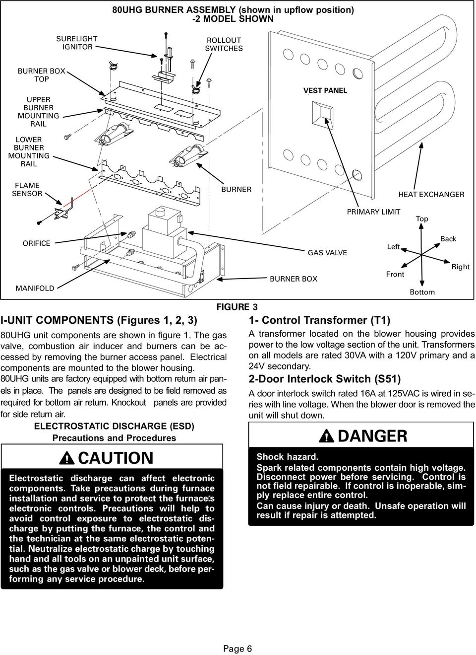
7 3 Furnace Control (A3) 80UHG 2, 3 Models 80UHG 2 and 3 model units are equipped with the Len nox SureLight ignition system. The system consists of ignition control board (figure 6 with control terminal desig nations in table 4) and ignitor (figure 7). The board and ig nitor work in combination to ensure furnace ignition and ignitor durability. The SureLight integrated board controls all major furnace operations. The board also features two LED lights for troubleshooting and two accessory termi nals rated at (4) four amps. See table 3 for troubleshoot ing diagnostic codes. Table 1 and 2 show jack plug termi nal designations. Units equipped with the SureLight board can be used with either electronic or electro me chanical thermostats without modification. The Sur elight ignitor is made of durable silicon nitride. Ignitor longevity is also enhanced by voltage ramping by the control board. The board finds the lowest ignitor tempera ture which will successfully light the burner, thus increas ing the life of the ignitor. Each time power is applied to the furnace, the SureLight board performs a selfcheck in cluding energizing the combustion air blower for a period of 1 second. PIN # TABLE 1 SureLight BOARD J156 (J2) TERMINAL DESIGNATIONS FUNCTION 1 Combustion Air Inducer Line 2 Ignitor Line 3 Combustion Air Inducer Neutral 4 Ignitor Neutral PIN # TABLE 2 SureLight BOARD J58 (J1) TERMINAL DESIGNATIONS FUNCTION 1 Primary Limit / Pressure Switch Out 2 Secondary Limit 3 24V 4 Not Used 5 Rollout Switch In 6 24V 7 Primary Limit In 8 Ground 9 Gas Valve In 10 Pressure Switch In 11 Rollout Switch Out 12 Gas Valve Out a Electronic Ignition (See Figure 5) On a call for heat the SureLight control monitors the com bustion air inducer pressure switch. The control will not be gin the heating cycle if the prove switch is closed (by passed). Once the prove switch is determined to be open, the combustion air inducer is energized. When the differ ential in the prove switch is great enough, the prove switch closes and a 15 second pre purge begins. If the prove switch is not proven within 2 1/2 minutes, the control goes into Watchguard Pressure Switch mode for a 5 minute re set period. After the 15 second pre purge period, the SureLight igni tor warms up for 20 seconds during which the gas valve opens at 19 seconds for a 4 second trial for ignition. The ignitor stays energized for the first second of the 4 second trial. 80UHG units equipped with control 10M9301: ignitor remains energized during the 4 second trial until flame is sensed. If ignition is not proved during the 4 second peri od, the control will try four more times with an inter purge and warm up time between trials of 35 seconds. After a to tal of five trials for ignition (including the initial trial), the control goes into Watchguard Flame Failure mode. After a 60 minute reset period, the control will begin the ignition sequence again. The SureLight control board has an added feature that prolongs the life of the ignitor. After a successful ignition, the SureLight control utilizes less power to energize the ig nitor on successive calls for heat. The control continues to ramp down the voltage to the ignitor until it finds the lowest amount of power that will provide a successful ignition. This amount of power is used for 255 cycles. On the 256th call for heat, the control will again ramp down until the low est power is determined and the cycle begins again. b Fan Time Control The fan on time of 45 seconds is not adjustable. Fan off time (time that the blower operates after the heat demand has been satisfied) can be adjusted by flipping the dip switches located on the SureLight integrated control. The unit is shipped with a factory fan off setting of 90 seconds. Fan off time will affect comfort and is adjustable to satisfy individual applications. See figure 4. FANOFF TIME ADJUSTMENT 60sec. 90sec. 120sec. 180sec. To adjust fan off timing, flip dip switch to desired setting. FIGURE 4 Page 7
 four amps. See table 3 for troubleshoot ing diagnostic codes.")
8 The SureLight board is equipped with two LED lights for troubleshooting. The diagnostic codes are listed below in table 3. TABLE 3 DIAGNOSTIC CODES MAKE SURE TO ID LED S CORRECTLY: REFER TO INSTALLATION INSTRUCTIONS FOR CONTROL BOARD LAYOUT. LED #1 LED #2 DESCRIPTION SIMULTANEOUS SLOW FLASH SIMULTANEOUS FAST FLASH SLOW FLASH OFF ALTERNATING SLOW FLASH SIMULTANEOUS SLOW FLASH SIMULTANEOUS FAST FLASH ON SLOW FLASH ALTERNATING SLOW FLASH Power Normal operation Also signaled during cooling and continues fan. Normal operation signaled when heating demand initiated at thermostat. Primary or Secondary limit open. Units with board 12L69: Limit must close within 5 trials for ignition or board goes into one hour limit Watchguard. Units with board 56L84: Limit must close within 3 minutes or board goes into one hour limit Watch guard. Pressure switch open or has opened 5 times during a single call for heat; OR: Blocked inlet/exhaust vent; OR: Condensate line blocked; OR: Pressure switch closed prior to activation of combustion air blower. Watchguard burners fail to ignite. SLOW FLASH OFF Flame sensed without gas valve energized. ON SLOW FLASH Rollout switch open. OR: 9 pin connector improperly attached. ON ON OFF ON OFF ON Circuit board failure or control wired incorrectly. FAST FLASH SLOW FLASH Main power polarity reversed. Switch line and neutral. SLOW FLASH FAST FLASH Low flame signal. Measures below 0.2 microamps. Replace flame sense rod. ALTERNATING FAST FLASH ALTERNATING FAST FLASH Improper main ground or line voltage below 75 volts; OR: Broken ignitor; OR: Open ignitor circuit. NOTE Slow flash equals 1 Hz (one flash per second). Fast flash equals 3 Hz (three flashes per second). Drop out flame sense current < 0.15 microamps SureLight Control Ignition Sequence (Control 56L8401 ONLY) ÉÉ ÉÉ ON OFF DEMAND CA BIGNITOR GAS VALVE INDOOR BLOWER SEC Pre Purge Ignitor Warmup Trial for Ignition Delay Purge ÉÉÉÉÉÉÉÉÉÉÉÉÉÉÉÉÉÉÉÉÉÉÉÉ ÉÉÉÉÉÉÉÉÉÉÉÉÉÉÉÉÉÉÉÉÉÉÉÉÉÉ ÉÉÉÉÉÉÉÉÉÉÉÉÉÉÉÉÉÉÉÉÉÉÉÉÉÉ ÉÉÉÉÉÉÉÉÉÉÉÉÉÉ ÉÉÉÉÉÉÉÉÉ *Blower on time will be 45 seconds after ignition. Blower off time will depend on OFF TIME" Setting. FIGURE 5 Blower On" Post Page 8

9

10

11

12
13
14
15 NOTE When unit is initially started, steps 1 through 11 may need to be repeated to purge air from pilot line.

16
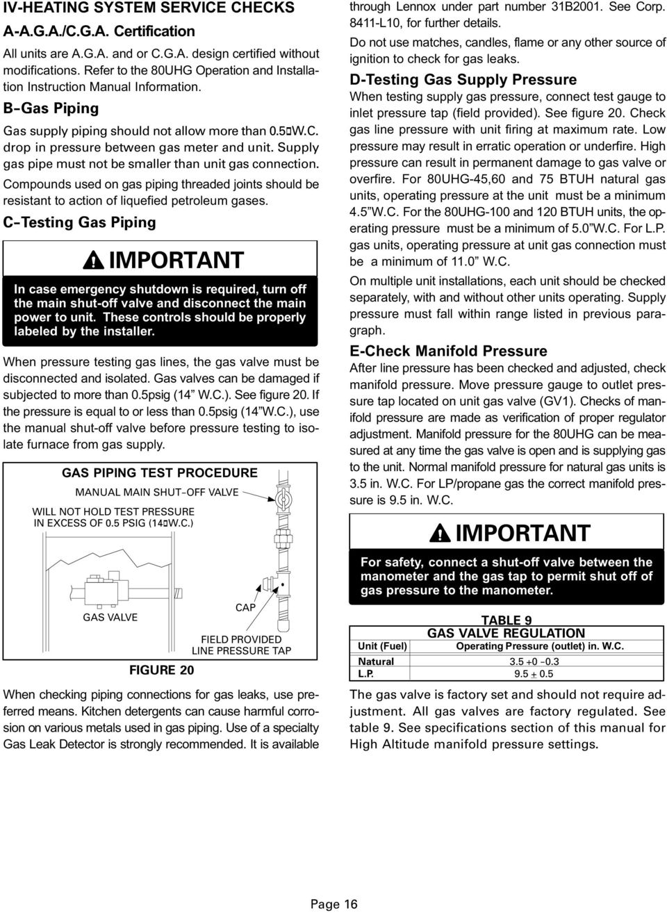
17
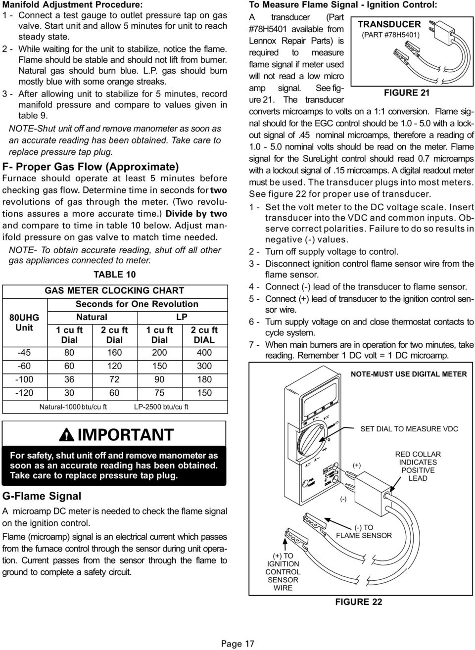
18
19

20

21
22
23
24
25
26 NORMAL HEATING MODE HEATING SEQUENCE CONTINUED ABNORMAL HEATING MODE 15SECOND COMBUSTION AIR INDUCER PREPURGE INITIATED BY CLOSED PRESSURE SWITCH. IGNITOR WARMUP 20 SECONDS. 4SECOND TRIAL FOR IGNITION. GAS VALVE OPENS. IGNITOR ENERGIZED FOR 1 SECOND AFTER VALVE OPENS. CONTROL 10M9301: IGNITOR ENERGIZED DURING TRIAL UNTIL FLAME SENSED. FLAME STABILIZATION PERIOD. 4 SECONDS FLAME RECTIFICATION CURRENT CHECK. CAN FLAME BE PROVEN WITHIN 4 SECONDS AFTER GAS VALVE OPENS? (0.15 microamps) FLAME PRESENT? NO NO NO IS VOLTAGE ABOVE 75 VOLTS? NO NO IS THERE A PROPER GROUND? NO IS IGNITOR INTACT AND CONNECTED? GAS VALVE OFF. COMBUSTION AIR INDUCER ON. INDOOR BLOWER OFF. HAS CONTROL FAILED TO SENSE FLAME FOR FIVE CONSECUTIVE TRIES DURING A SINGLE HEAT DEMAND? WATCHGUARD MODE. GAS VALVE OFF. COMBUSTION AIR INDUCER OFF. INDOOR BLOWER OFF WITH DELAY LEDs SIGNAL WATCHGUARD FAILURE CODE. IS 60MINUTE RESET PERIOD COMPLETE? HAS CONTROL RESET IGNITION SEQUENCE FOUR TIMES? LEDS SIGNAL ALTERNATING FAST FLASH NO NO FLAME SIGNAL ABOVE 0.2 MICROAMPS? INDOOR BLOWER ON DELAY BEGINS (45 seconds.) PRIMARY AND SECONDARY LIMIT SWITCHES CLOSED? NO NO LOW FLAME SIGNAL (Does not affect operation of control) LED #1 SLOW FLASH LED #2 FAST FLASH GAS VALVE DE ENERGIZED. COMBUSTION AIR INDUCER DE ENERGIZED. INDOOR BLOWER ON UNTIL SWITCH CLOSES. LED #1 SLOW FLASH. LED #2 ON. IS LIMIT SWITCH CLOSED? HAS PRIMARY SECONDARY LIMIT RESET (CLOSED) WITHIN 3 MINUTES? LIMIT SWITCH WATCHGUARD MODE. GAS VALVE OFF. COMB. AIR INDUCER OFF. INDOOR BLOWER OFF WITH DELAY. LED#1 SLOW FLASH LED#2 ON. IS 60 MINUTE RESET PERIOD COMPLETE? NO ROLLOUT SWITCH CLOSED? COMBUSTION AIR PRESSURE SWITCH CLOSED? THERMOSTAT DEMAND SATISFIED. LED #1 & #2 SIMULTANEOUS SLOW FLASHES. COMB. AIR INDUCER CONTINUES 5SECOND POST PURGE AFTER T STAT DEMAND IS SATISFIED. INDOOR AIR BLOWER COMPLETES SELECTED OFF" DELAY BEFORE SHUTTING OFF. NO NO GAS VALVE POWER OFF. COMBUSTION AIR INDUCER POWER ON. INDOOR BLOWER ON LED #1 ON. LED #2 SLOW FLASH. SEQUENCE HOLDS UNTIL ROLLOUT SWITCH IS RESET AND MAIN POWER IS INTERUPTED OR THERMOSTAT IS CYCLED OFF/ON FOR 1 TO 20 SEC. GAS VALVE DE ENERGIZED. COMBUSTION AIR INDUCER ON. INDOOR BLOWER OFF WITH DELAY LED #1 OFF. LED #2 SLOW FLASH. HAS CAB SWITCH CLOSED IN 2.5 MINUTES? NO 5MINUTE PRESSURE SWITCH WATCHGUARD MODE. Page 26
27
28
29
30
31
32
33
34
G26 Corp. 9721-L11 Revised 07-2001 LENNOXOEMPARTS.COM. Service Literature G26 SERIES UNITS
 Service Literature G26 SERIES UNITS G26 series units are high-efficiency upflow gas furnaces manufactured with DuralokPlust aluminized steel clamshell-type heat exchangers. G26 units are available in heating
http://waterheatertimer.org/how-to-troubleshoot-gas-water-heater.html
 http://waterheatertimer.org/how-to-troubleshoot-gas-water-heater.html APPLY POWER TO APPLIANCE FIELD WIRING CORRECT? DPLAY ERROR CODE 1 OR 2 Intelli-Vent TM Sequence of Operation REQUEST FOR HEAT PRESENT?
PRODUCT DESIGN. 5. Furnace awaits call from thermostat.
 Goodman / Amana Distinctions Brand Single-Stage 80% or 90% Furnaces White-Rodgers 50A55 Integrated Ignition Control 1. 115 VAC power applied to furnace. 2. Integrated ignition control module performs internal
Commercial Gas Furnace Upflow
 Commercial Gas Furnace Upflow Model G24-200 80% A.F.U.E. 200,000 Btuh Input Heating Cap. 7.5 or 10 Tons Nominal Add-On Cooling GUK FEATURES Certified by A.G.A./C.G.A. Laboratories. Heavy gauge painted
TECHNICAL SERVICE DEPARTMENT Technical Service Bulletin 1-800-432-8373. 2 Inch PowerVent LED Indicator Explanations & Troubleshooting Table
 New Robertshaw control valve was introduced in May 2008 as a replacement part. See last page for troubleshooting this replacement part. All voltage inputs are 120V. All electrical connectors are Molex
Fossil fuel heating equipment
 Fossil fuel heating equipment principles and troubleshooting techniques Application Note This application note was written to provide you with an understanding of the basic principles of fossil fuel heating
XV80 UPFLOW/HORIZONTAL 2-STAGE, VARIABLE SPEED GAS-FIRED FURNACE
 UPF/HORIZONTAL 2-, VARIABLE SPEED GAS-FIRED FURNACE XV80 MODELS TUD2B060A9V3VB, TUD2B080A9V3VB TUD2C080A9V4VB, TUD2C080B9V4VB TUD2B00A9V3VB, TUD2C00A9V5VB TUD2C00B9V5VB, TUD2DA9V5VB TUD2DB9V5VB, TUD2DA9V5VB
Revised 07-2001 G24M SERIES UNITS
 Corp. 9723-L12 Service Literature Revised 07-2001 G24M series units are mid-efficiencygas furnacesmanufactured with tubular steel heat exchangers formed of aluminized steel. G24M units are available in
M7RL Series TECHNICAL SPECIFICATIONS. FEATURES and BENEFITS. High Efficiency / Direct Vent Condensing Downflow Gas Furnace
 TECHNICAL SPECIFICATIONS M7RL Series High Efficiency / Direct Vent Condensing Downflow Gas Furnace Induced Draft - 9%+ AFUE Input 4,000 thru 7,000 Btuh The high efficiency downflow gas furnace is especially
Cooling Capacity CFM range @.5 in. w.c. (125 Pa)
") N8MXL Product Specifications 80% ECM Single Stage Heating Furnace EASIER TO SELL 80% AFUE Flame roll out sensors standard Category I venting Blocked vent switch 24 VAC humidifier terminal Electronic air
N8MXL Product Specifications 80% ECM Single Stage Heating Furnace EASIER TO SELL 80% AFUE Flame roll out sensors standard Category I venting Blocked vent switch 24 VAC humidifier terminal Electronic air
XV 95. Upflow/ Horizontal Left, Downflow/ Horizontal Right Variable Speed Two Stage Condensing Gas-Fired Furnace PUB. NO.
 Upflow/ Horizontal Left, Downflow/ Horizontal Right Speed Two Stage Condensing Gas-Fired Furnace XV 95 TUH2B060A9V3VB TUH2B080A9V3VB TUH2B080A9V4VB TUH2C100A9V4VB TUH2C100A9V5VB TUH2D120A9V5VB Direct Vent
Gas Unit Heaters Duct Furnaces Horizontal - 60 HZ Form No. LF24-100-400 (10/2011) LF24 Standard
 LF24 Standard") LF Standard Features Horizontal unit heaters are compact in design and easy to install. Steady State Efficiencies of up to 80.%. Ideal for economical commercial heating systems. Shipped completely assembled
LF Standard Features Horizontal unit heaters are compact in design and easy to install. Steady State Efficiencies of up to 80.%. Ideal for economical commercial heating systems. Shipped completely assembled
http://waterheatertimer.org/how-to-troubleshoot-gas-water-heater.html
 http://waterheatertimer.org/how-to-troubleshoot-gas-water-heater.html TECHNICAL SERVICE DEPARTMENT Effective October 2007, we transitioned to the White Rodgers (Intelli-Vent TM )Thermostat Control for
SL280UHV SERIES GAS FURNACE WARNING
 2010 Lennox Industries Inc. Dallas, Texas, USA 506677 01 11/2010 Supersedes 506409 01 SL280UHV SERIES GAS FURNACE Litho U.S.A. FIRE OR EXPLOSION HAZARD. Failure to follow safety warnings exactly could
SERVICE MANUAL FOR 6535 SERIES TWO TON HIGH EFFICIENCY PACKAGED HEAT PUMPS
 SERVICE MANUAL FOR 6535 SERIES TWO TON HIGH EFFICIENCY PACKAGED HEAT PUMPS TABLE OF CONTENTS 1. Warnings...2 2. Accessibility Of Appliance...3 3. Unit Dimensions And Specifications...3 4. Unit Specifications
Communicating Controls Service Manual
 Communicating Controls Service Manual History 1977 1991 Theory of Operation Common Components Telephone Access Module Service/Troubleshooting Table of Contents Warnings and Cautions... 2 Theory of Operation
37E73A-903 & 906 INTELLI-VENT
 37E73A-903 & 906 INTELLI-VENT Water Heater Thermostat Control Installation Instructions For Natural Gas Only Operator: Save these instructions for future use FAILURE TO READ AND FOLLOW ALL INSTRUCTIONS
USER S, MAINTENANCE and SERVICE INFORMATION MANUAL
 CONTENTS SAFETY INFORMATION................ 2 FOR YOUR SAFETY....................... 2 SYSTEM OPERATION.................. 2 THERMOSTATS........................... 2 INTERMITTENT IGNITION DEVICE...........
Cooling Capacity CFM range @.5 in. w.c. (125 Pa)
") 96% AFUE, Two Stage ECM Gas Furnace EASIER TO SELL 96% AFUE, all models, all positions Two stage heating operation Xtra SEER ECM blower motor Supports two stage cooling units Dehumidification feature in
96% AFUE, Two Stage ECM Gas Furnace EASIER TO SELL 96% AFUE, all models, all positions Two stage heating operation Xtra SEER ECM blower motor Supports two stage cooling units Dehumidification feature in
Model 7586. Description / Applications. Intermittent Pilot Gas Ignition Control
 PARTS & ACCESSORIES Model 7586 Intermittent Pilot Gas Ignition Control Description / Applications The Beckett GeniSys Intermittent Pilot Gas Ignition Control is a 24 Vac gas ignition and safety control.
prestige Condensing Water Boiler SERVICE TECHNICIAN S TROUBLE SHOOTING GUIDE 2008-36 TSG-PRESTIGE Date revised: 12/6/10
 prestige Condensing Water Boiler SERVICE TECHNICIAN S TROUBLE SHOOTING GUIDE Date revised: 12/6/10 2008-36 TSG-PRESTIGE Table of Contents INTRODUCTION Page 1-2 SERVICING TIPS AND INSTRUCTIONS Page 3-4
G670 Intermittent Pilot Ignition Controls
 Installation Sheets Manual 121 Gas Combustion Combination Controls and Systems Section G Technical Bulletin Issue Date 0300 Intermittent Pilot Ignition Controls Figure 1: Intermittent Pilot Ignition Control
48/50EJ,EK,EW,EY038, 044, 048 SINGLE-PACKAGE COOLING UNITS VARIABLE VOLUME CONSTANT VOLUME FACTORY-INSTALLED OPTIONAL HEAT
 48/50E-4SB 48/50EJ,EK,EW,EY038, 044, 048 SINGLE-PACKAGE COOLING UNITS VARIABLE VOLUME CONSTANT VOLUME FACTORY-INSTALLED OPTIONAL HEAT GAS HEAT ELECTRIC HEAT PERFORMANCE DATA CERTIFIED DIMENSION PRINT CERTIFIED
Cooling Capacity CFM range @.5 in. w.c. (125 Pa)
") 96% AFUE, Single Stage, ECM Gas Furnace EASIER TO SELL 96% AFUE, all models all positions Xtra SEER ECM blower motor Supports two stage cooling units Dehumidification feature in cooling California NOx
96% AFUE, Single Stage, ECM Gas Furnace EASIER TO SELL 96% AFUE, all models all positions Xtra SEER ECM blower motor Supports two stage cooling units Dehumidification feature in cooling California NOx
HP 5 Microprocessor Control for Mammoth Water Source Heat Pumps
 HP 5 Microprocessor Control for Mammoth Water Source Heat Pumps Operation and Maintenance Manual Model: 71028004 Applies to: Single Circuit Water-to-Water Twin Circuit Units Without DDC Controls MAMM WHSP
WARNING CAUTION 21V51U-843 DESCRIPTION PRECAUTIONS
 The kit Includes: CAUTI 21V51U-843 Integrated Two-Stage/Variable Speed Motor Hot Surface Ignition Control Kit INSTALLATI INSTRUCTIS Operator: Save these instructions for future use! FAILURE TO READ AND
TECHNICAL MANUAL GDS8 & GHS8
 TECHNICAL MANUAL AL GDS8 & GHS8 33-3/8" 80% Gas Furnace Units Refer to Service Manual RS6610004 for installation, operation, and troubleshooting information. All safety information must be followed as
12288 Side Road 22, Wainfleet, Ontario Canada L0S 1V0 Phone: 905-899-3473 www.easyradiantworks.com Fax: 905-899-2262
 12288 Side Road 22, Wainfleet, Ontario Canada L0S 1V0 Phone: 905-899-373 www.easyradiantworks.com Fax: 905-899-2262 Installation & Operating Instructions For EASY RADIANT EZ, EZU, SH & SHU Radiant Tube
G9MXE. Product Specifications
 Up to 96% AFUE, Single Stage, ECM Gas Furnace EASIER TO SELL Up to 96% AFUE, all models all positions California NOx approved Select models earn the ENERGY STAR (See below, indicated with check mark.)
F9MXE. Product Specifications
 96% AFUE, Single Stage, ECM Gas Furnace EASIER TO SELL 96% AFUE, all models all positions Select models earn the ENERGY STAR (See below, indicated with check mark.) Xtra SEER ECM blower motor Supports
INSTALLATION INSTRUCTIONS MC95HAE-1 MASTER CONTROLLER
 INSTALLATION INSTRUCTIONS MC95HAE-1 MASTER CONTROLLER Bard Manufacturing Company, Inc. Bryan, Ohio 43506 Since 1914...Moving ahead just as planned. Manual : 2100-360B Supersedes: 2100-360A File: Volume
Residential/Commercial Gas Condensing High Efficiency Tankless Water Heaters
 Residential/Commercial Gas Condensing High Efficiency Tankless Water Heaters FEATURES ULTRA-LOW NOx CONDENSING TECHNOLOGY PROVIDES UNPRECEDENTED 0.95 ENERGY FACTOR DURABLE HEAT EXCHANGER Primary Heat Exchanger
ECM. Service Guide. www.thedealertoolbox.com
 ECM Service Guide www.thedealertoolbox.com ECM Table of Contents Service Guide Working on the motor with power connected may result in electrical shock or other conditions that may cause personal injury,
The formula for finding CFM is: CFM = BTUH OUTPUT_ Temp Rise (ACF)* *Altitude correction factor below 1000ft = 1.08
* *Altitude correction factor below 1000ft = 1.08") Air Volume Requirement Air conditioning systems are engineered with a specific amount of indoor air passing across the surface of the evaporator coil. The amount of air is measured in cubic feet per minute.
Air Volume Requirement Air conditioning systems are engineered with a specific amount of indoor air passing across the surface of the evaporator coil. The amount of air is measured in cubic feet per minute.
543-0032-00, 943-0032-00. User s Manual
 543-0032-00, 943-0032-00 User s Manual 1 Comfort Alert Diagnostics Faster Service And Improved Accuracy The Comfort Alert diagnostics module is a breakthrough innovation for troubleshooting heat pump and
its ELECTRIC POSITION for electric heat, or set the units fan control appropriately to ELECTRIC or another appropriate setting.
 Troubleshooting Poor Temperature Regulation This page lists problems that may affect the temperature performance of your LUX thermostat with suggested resolutions. For more detailed information please
Air Conditioning Sign-Off Sheet
 Air Conditioning Sign-Off Sheet Printed Technician Name Address Social Security Number Telephone Number City State Zip Code Install Or Verify The Accuracy Of An Air Conditioner s Installation The candidate
USER MANUAL WARNING! CONTENTS MODEL 1 SPECIFICATIONS READ ALL INSTRUCTIONS BEFORE PROCEEDING. Non-Programmable Single Stage Heat/Cool Thermostat
 Builder MODEL 1010 Series Non-Programmable Single Stage Heat/Cool Thermostat USER MANUAL Compatible with low voltage single stage gas, oil or electric heating or cooling systems, including single stage
TECHNICAL GUIDE 95.5% SINGLE STAGE GAS-FIRED RESIDENTIAL MULTI-POSITION GAS FURNACES MODELS: TG9S DESCRIPTION FEATURES
 TECHNICAL GUIDE 95.5% SINGLE STAGE GAS-FIRED RESIDENTIAL MULTI-POSITION GAS FURNACES MODELS: TG9S NATURAL GAS 40-130 MBH INPUT Due to continuous product improvement, specifications are subject to change
INSTALLER S SYSTEM SETUP GUIDE
 2009 Lennox Industries Inc. Dallas, Texas, USA INSTALLER S SYSTEM SETUP GUIDE icomfort Thermostat Touch Screen Programmable Communicating Thermostat CONTROLS 506052 01 11/09 Litho U.S.A. Shipping and Packing
DVI 980/982 (Honeywell Nr. S4865) Gas Burner Safety Control
 Gas Burner Safety Control") Gas Burner Safety Control For 1- or 2-stage forced draught and atmospheric gas burners, with DC valves Possible flame detectors: - Ionisation probe - Infrared flicker detector 1020.1 - UV flame sensor
Gas Burner Safety Control For 1- or 2-stage forced draught and atmospheric gas burners, with DC valves Possible flame detectors: - Ionisation probe - Infrared flicker detector 1020.1 - UV flame sensor
OPERATIONAL CHECKS & SAFETY CIRCUIT DESCRIPTION
 OPERATIONAL CHECKS & SAFETY CIRCUIT DESCRIPTION Integrated control module performs internal checks. Integrated control module displays 8 8 on dual 7-segment display LED s. Integrated control module monitors
SIMPLE ELECTRONIC IGNITION WIRE DIAGRAM THERMOSTAT (3) PV PILOT BURNER/IGNITOR - SENSOR Q345A (9) SPARK (4) GND (BURNER) CHASSIS GND
 PV PILOT BURNER/IGNITOR - SENSOR Q345A (9) SPARK (4) GND (BURNER) CHASSIS GND") Honeywell Electronic Ignition Troubleshooting Tech Tip April 2007 The Honeywell S8610H Intermittent Pilot Module provides the ignition sequencing, pilot spark, pilot flame monitoring, Pilot Valve (PV)
Honeywell Electronic Ignition Troubleshooting Tech Tip April 2007 The Honeywell S8610H Intermittent Pilot Module provides the ignition sequencing, pilot spark, pilot flame monitoring, Pilot Valve (PV)
Flame Conductivity VS Flame Rectification Systems
 Flame Conductivity VS Flame Rectification Systems There are two basic principles in flame rod detection systems-flame conductivity and flame rectification. Conductivity systems are, for the most part no
CONTROLS KITS AND ACCESSORIES. 507240-01 12/2014 Supersedes10/2014
 2014 Lennox Industries Inc. Dallas, Texas, USA CONTROLS KITS AND ACCESSORIES 507240-01 12/2014 Supersedes10/2014 Litho U.S.A. Equipment Interface Module Installation Instructions for the Equipment Interface
C. Burner management system to follow requirements of Industrial Risk Insurers (IRI).
.") SECTION 23 52 30 PART 1 - GENERAL 1.01 RELATED WORK A. Section 23 05 00: Common Work Results for HVAC B. Section 23 25 00: Chemical Water Treatment C. Section 23 51 23: Flue Piping 1.02 QUALITY ASSURANCE
SECTION 23 52 30 PART 1 - GENERAL 1.01 RELATED WORK A. Section 23 05 00: Common Work Results for HVAC B. Section 23 25 00: Chemical Water Treatment C. Section 23 51 23: Flue Piping 1.02 QUALITY ASSURANCE
SERVICE MANUAL 12VDC WALL THERMOSTAT AIR CONDITIONING SYSTEMS ROOFTOP UNITS ONLY
 SERVICE MANUAL 12VDC WALL THERMOSTAT AIR CONDITIONING SYSTEMS ROOFTOP UNITS ONLY! WARNING - SHOCK HAZARD! TO PREVENT THE POSSIBILITY OF SEVERE PERSONAL INJURY, DEATH, OR EQUIPMENT DAMAGE DUE TO ELECTRICAL
Heating, Ventilation, Air Conditioning and Refrigeration (HVACR)
") Heating, Ventilation, Air Conditioning and Refrigeration (HVACR) I. Demonstrate safety skills in typical HVACR work situations to NATE Core Installer Knowledge Areas for Technician Excellence for Safety
Heating, Ventilation, Air Conditioning and Refrigeration (HVACR) I. Demonstrate safety skills in typical HVACR work situations to NATE Core Installer Knowledge Areas for Technician Excellence for Safety
TB-A028-06 - A. O. SMITH - FVIR INTELLI-VENT TROUBLESHOOTING CHART # LED STATUS PROBLEM SOLUTION
 1 2 3 4 5 Inadequate or no earth ground sensed by the Intelli-Vent control. Power supply to Intelli-Vent control has reversed polarity. Pressure switch circuit remaining closed for more than 5 seconds
Heating Basics Gas Valve Systems
 Heating Basics Gas Valve Systems UNI-LINE PRODUCT KNOWLEDGE 2010 Invensys. All Rights Reserved. The names, logos, and taglines identifying the products and services of Invensys are proprietary marks of
Commercial Gas Water Heater
 Commercial Gas Water Heater 3-Year Limited Tank/1-Year Limited Parts Warranty* The Polaris has a high grade 444 stainless steel tank with brass connections for years of dependable, trouble-free service
ABC-1000 Automatic Boiler Level Controller Operation and Installation Manual
 QUALITY STEAM SPECIALTIES SINCE ABC-1000 Automatic Boiler Level Controller Operation and Installation Manual Section: C500 Bulletin: C500.40 Date: 06-26-01 Supersedes: New PRODUCT DESCRIPTION: The Clark-Reliance
EFFECTIVE OCTOBER 2005. Atwood Furnaces. and Digital Thermostats
 EFFECTIVE OCTOBER 2005 Atwood Furnaces and Digital Thermostats Unique 2-Stage System Set the temperature, turn the thermostat on automatic and let the furnace take over! During cold start-ups, the furnace
ELECTRIC POSITION for electric heat, then confirm with Fan Test below.
 Troubleshooting Poor Temperature Regulation This page lists problems that may affect the temperature performance of your LUX thermostat with suggested resolutions. For more detailed information please
USERS GUIDE. LOGIC Heat 12, 15, 18, 24, 30. For installation guide see reverse of book
 USERS GUIDE LOGIC Heat 12, 15, 18, 24, 30 For installation guide see reverse of book When replacing any part on this appliance, use only spare parts that you can be assured conform to the safety and performance
Commercial Gas Water Heaters
 POWERED BURNER MODELS LARGE-VOLUME POWERED BURNER FEATURES The large-volume powered burner line includes the largest, most powerful A. O. Smith tanktype gas water heaters. With tank capacities up to 600
SECTION 23 81 03 - PACKAGED ROOFTOP AIR CONDITIONING UNITS NON-CUSTOM
 SECTION 23 81 03 - PACKAGED ROOFTOP AIR CONDITIONING UNITS NON-CUSTOM PART 1 - GENERAL 1.1 SUMMARY A. Section Includes: 1. Packaged rooftop air conditioning unit (5 tons and smaller). 2. Roof curb. 1.2
User s Information/Installation Instructions
 Outdoor Heat Pump User s Information/Installation Instructions 13 SEER R-410A High Efficiency Split System These units have been designed and tested for capacity and effi ciency in accordance with A.R.I.
INTELLI-VENT CONTROL INFORMATION When Used On Gas, Residential, Power Vented Water Heaters
 INTELLI-VENT CONTROL INFORMATION When Used On Gas, Residential, Power Vented Water Heaters Printed in the USA 0605 Part No. GTC-070 R3 Revision 2 includes updated troubleshooting information for error
Certification Information. Qualifications. Test Specifications. Gas Furnaces Industry References
 GAS FURNACES SERVICE CERTIFICATION Certification Information Scope - Tests a candidate's knowledge of the installation, service, maintenance, and repair of HVAC systems. System sizes are limited to 400,000
Eclipse Veri-Flame Single Burner Monitoring System Model 5600 Version 1
 Instruction Manual 88 9/5/008 Eclipse Veri-Flame Single Burner Monitoring System Model 5600 Version Modulation Model No Purge Model Purge Model Co p y r i g h t Copyright 008 by Eclipse, Inc. All rights
! WARNING. McDonnell & Miller Installation & Maintenance Instructions MM-217(I) Series 150S and 157S (Snap Switch, All Models except 157S-RB-P)
 Series 150S and 157S (Snap Switch, All Models except 157S-RB-P)") Series 150S and 157S (Snap Switch, All Models except 157S-RB-P) Low Water Cut-Off/Pump Controllers For Steam Boilers and Other Level Control Applications McDonnell & Miller Installation & Maintenance Instructions
Series 150S and 157S (Snap Switch, All Models except 157S-RB-P) Low Water Cut-Off/Pump Controllers For Steam Boilers and Other Level Control Applications McDonnell & Miller Installation & Maintenance Instructions
ELITE SERIES Up Flow / Horizontal Precision Speed Blower
 G S F U R N C E S G50UHi ELITE SERIES Up Flow / Horizontal Precision Speed Blower E N G I N E E R I N G D T Bulletin No. 210380 ugust 2005 Supersedes May 2004 FUE 80% Input 66,000 to 132,000 Btuh Nominal
Circuit breaker panel. Power supply for condensing unit. Power supply for furnace. Air handler (Furnace)
") UNIT OBJECTIVES Describe the concept of year-round air conditioning List three typical year-round air conditioning system types List the five ways to condition the air Determine airflow for a cooling system
UNIT OBJECTIVES Describe the concept of year-round air conditioning List three typical year-round air conditioning system types List the five ways to condition the air Determine airflow for a cooling system
Veri-Flame Single Burner Monitoring System
 Instruction Manual 88 6//06 Veri-Flame Single Burner Monitoring System Model 5600 Version.2 Modulation Model No Purge Model Purge Model Copyright Disclaimer notice Copyright 2006 by Eclipse, Inc. All rights
Installation Instructions
 H5HK Series Installation Instructions 3 Phase Electric Heater Kits 7.5 and 0 TON Package A/C Systems Description Installation of 08/40V and 480V H5HK 3 Phase Heater Kits in 7.5 and 0 TON Packaged Air Conditioners.
E2 Series Electric Furnaces
 E2 Series Electric Furnaces Service Manual Table of Contents Electrical Requirements... 10 Codes, Specifications Requirements... 10 Connection Supply Service Wires... 10 Furnace Sequence of Operation...
WHITE-RODGERS COMFORT-SET 90 SERIES
 INSTALLATI DESCRIPTI WHITE-RODGERS COMFORT-SET 90 SERIES MULTI-STAGE INSTALLATI/CFIGURATI This White-Rodgers Automatic Setback Digital Thermostat uses microcomputer technology to provide precise time and
DMG 970. Gas Burner Safety Control. For 2-stage forced draught and combi oil/gas burners
 A Honeywell Company Gas Burner Safety Control For 2-stage forced draught and combi oil/gas burners Possible flame detectors: - Ionisation probe - Infrared flicker detector 1020 - UV flame sensor UVD 971
HEAT HEAT COOL HEAT PUMP COOL
 OWNER S MANUAL RESIDENTIAL THERMOSTAT P/N P374-1800 HEAT COOL HEAT PUMP Su AUTO 0I20: Pm 74 COOL HEAT 27 7-DAY MABLE DIGITAL THERMOSTAT 3 Configurable Outputs Accepts Optional Humidity Module: Control
PANASONIC TROUBLE SHOOTING GUIDE
 A General Guide To Room Style Products Pipework Pipe sizes and lengths should be as the relevant Technical Guide Both lines should be insulated No line accessories or oil traps should be fitted In cooling
For installation guide see reverse of book
 USERS GUIDE LOGIC Combi 24, 30, 35 For installation guide see reverse of book When replacing any part on this appliance, use only spare parts that you can be assured conform to the safety and performance
MODEL 2202IQ (1991-MSRP $549.00)
") F O R T H E L O V E O F M U S I C F O R T H E L O V E O F M U S I C MODEL 2202IQ (1991-MSRP $549.00) OWNER'S MANUAL AND INSTALLATION GUIDE INTRODUCTION Congratulations on your decision to purchase a LINEAR
F O R T H E L O V E O F M U S I C F O R T H E L O V E O F M U S I C MODEL 2202IQ (1991-MSRP $549.00) OWNER'S MANUAL AND INSTALLATION GUIDE INTRODUCTION Congratulations on your decision to purchase a LINEAR
HVAC-32A. Operation Manual. Specifications. Digital Multistage Air Conditioning Controller with inbuilt Outside Air Economy function
 Specifications Supply Voltage 240VAC @ 0.07Amps or 24VAC @ 0.380Amps Relays 240V @ 12A max (resistive) / Comp1,2,3, Aux Ht, Rv O/B) Fuses (Equipment) 15 Amps Maximum 3AG Control Range Minus 10 to 50C Control
LOBOY 16 AIR CONDITIONERS
 INSTRUCTION MANUAL FOR: LOBOY 16 AIR CONDITIONERS McLean Midwest Corp. dba: McLean Cooling Technology 11611 Business Park Blvd. N Champlin, MN 55316 Tel: 763-323-8200 Fax: 763-576-3200 www.mcleancoolingtech.com
SERVICE INSTRUCTIONS
 SERVICE INSTRUCTIONS 18, 20,24, 26L Integrity Electronic Gas Continuous Flow Water Heater TM031 Reevvi issi ion:: B Publissheed:: Feebrruaarryy 0088 871018 871020 871024 871024-B 871024-C 871026 871026-B
How To Control A Thermostat
 CONTENTS Installation Instructions for Heating & Air Conditioning 1F72 5/2 Day Programmable Heat Pump Thermostat Preparations... 1 Thermostat Details... 1 Removing Old Thermostat... 1-2 Mounting and Wiring...
Operational Overview and Controls Guide. Two or Three Pump IronHeart Lite with Variable Frequency Drives
 DOCUMENT: ECSEQ6-0 EFFECTIVE: 09/23/10 SUPERSEDES: Operational Overview and Controls Guide Two or Three Pump IronHeart Lite with Variable Frequency Drives 6700 Best Friend Road. Norcross, GA 30071. (770)
M1 Series. M1G and M1M Furnaces. Service Manual
 M1 Series M1G and M1M Furnaces Service Manual D. C. B. A. Typical meters used to service M1 furnaces. A. Differential Pressure Gauge B. Volt-Ohm Meter C. Manometer D. Inclined Manometer TABLE OF CONTENTS
WMSLW / WMBLWH Series Hydronic Upflow/Horizontal Left or Right, Heating and Cooling Air Handler
 WMSLW / WMBLWH Series Hydronic Upflow/Horizontal Left or Right, Heating and Cooling Air Handler Installation Operation Maintenance The WMSLW/WMBLW series is designed for installation in a closet, utility
36G22, 36G23, 36G24 & 36G52 36J22, 36J23, 36J24 & 36J52 DSI and HSI Single Stage Combination Gas Valve
 Operator: Save these instructions for future use! FAILURE TO READ AND FOLLOW ALL INSTRUCTIONS CAREFULLY BEFORE INSTALLING OR OPERATING THIS CONTROL COULD CAUSE PERSONAL INJURY AND/OR PROPERTY DAMAGE. DESCRIPTION
ICM1 / ICM2 CAUTION CAUTION. Service Literature Variable Speed Motors. I Introduction
 Service Literature Variable Speed Motors ICM / ICM Corp. 05 L Revised 0 00 I Introduction This manual is meant to be a helpful guide in servicing Lennox residential split system products equipped with
Factory owners must ensure the boiler is:
 Factory owners must ensure the boiler is: * Registered with the Boilers and Pressure Vessels Division, Labour Department * Examined by an appointed examiner and has a valid certificate of fitness * Supervised
Protect your home s major mechanical systems with Main Street Mechanical s Home Service Agreement.
 Protect your home s major mechanical systems with Main Street Mechanical s Home Service Agreement. The benefits of a Home Service Agreement Provides peace of mind Regularly scheduled maintenance will keep
How To Buy A Lennox Power System
 HVAC for Schools A Comprehensive Look at Products for a Clean, Comfortable Learning Environment Why Schools Choose Lennox Even as resources for schools continue to be constrained, education leaders and
INSTALLER'S GUIDE. Supplementary Electric Heaters 18-GJ08D1-1. Table of Contents
 INSTALLER'S GUIDE ALL phases of this installation must comply with NATIONAL, STATE AND LOCAL CODES Models: BAYEAAC051A BAYEAAC05LG1A BAYEAAC081A BAYEAAC08LG1A BAYEAAC101A BAYEAAC10LG1A BAYEABC151A BAYEABC201A
ARMSTRONG AIR HEAT PUMPS www.armstrongair.com
 INDEX ELECTRIC FURNACE MODULAR AIR SYSTEM EFC/EFV... 5-10 electric Heat Kits... 5-11 evaporator coils EC1P / EM1P UPFLOW / COUNTERFLOW APPLICATIONS and upflow / horizontal applications (CASED)... 5-6 5-7
800-292-3279 916 638-0828
 800-292-3279 916 638-0828 http://easycleansystems.com/heaters/heater-parts.html VAL6 KBE5S and KBE5L Service manual KBE5S 1 2 Specifications Type VAL6 KBE5S Heat Output 111,000BTU/h Fuel Kerosene, Diesel
USERS GUIDE. LOGIC Combi 24, 30, 35. For installation guide see reverse of book
 USERS GUIDE LOGIC Combi 24, 30, 35 For installation guide see reverse of book When replacing any part on this appliance, use only spare parts that you can be assured conform to the safety and performance
with MERCURY FREE 1 HP Relays ! WARNING Before using this product read and understand instructions.
 B Installation & Maintenance Instructions MM-414 Series 150E and 157E Low Water Cut-Off/Pump Controllers For Steam Boilers and Other Level Control Applications A Typical Applications: Primary or secondary
Annual Service Agreement
 Annual Service Agreement 462 Main Street P.O. Box 130 Royersford, PA 19468 610-948-7220 www.plottsenergy.com GAS OIL HEAT PUMP AIR CONDITIONING A family owned and operated business since 1949. We are here
DKG 972 Gas Burner Safety Control
 A Honeywell Company Gas Burner Safety Control For 2-stage atmospheric gas burners Flame detection: - Ionisation probe - Infrared-flicker detector IRD 1020.1 - UV flame sensor UVD 971 EN1C-0127SZ20 R0305
EP 2 354 708 A2 (19) (11) EP 2 354 708 A2 (12) EUROPEAN PATENT APPLICATION. (43) Date of publication: 10.08.2011 Bulletin 2011/32
 (11) EP 2 354 708 A2 (12) EUROPEAN PATENT APPLICATION. (43) Date of publication: 10.08.2011 Bulletin 2011/32") (19) (12) EUROPEAN PATENT APPLICATION (11) EP 2 354 708 A2 (43) Date of publication:.08.2011 Bulletin 2011/32 (51) Int Cl.: F24H 3/08 (2006.01) F24H 8/00 (2006.01) (21) Application number: 111536.8 (22)
(19) (12) EUROPEAN PATENT APPLICATION (11) EP 2 354 708 A2 (43) Date of publication:.08.2011 Bulletin 2011/32 (51) Int Cl.: F24H 3/08 (2006.01) F24H 8/00 (2006.01) (21) Application number: 111536.8 (22)
G6 Series. 90+ High Efficiency Upflow/Downflow Models. Service Manual
 G6 Series 90+ High Efficiency Upflow/Downflow Models Service Manual D. C. B. A. Typical meters used to service furnaces. A. Differential Pressure Gauge B. Volt-Ohm Meter C. Manometer D. Slant Gauge TABLE
LANDFILL GAS ENCLOSED FLARE SYSTEM
 LANDFILL GAS ENCLOSED FLARE SYSTEM Part 1. General 1.01 Description A. Information within this specification describes an enclosed flare system designed specifically for the combustion of landfill gas.
Evaluate, Clean, and Tune Guidance
 Evaluate, Clean, and Tune Guidance The Evaluate, Clean and Tune (ECT) process serves three essential purposes in the Weatherization Assistance Program (WAP). The first is to evaluate the existing system
USER S INFORMATION MANUAL
 USER S INFORMATION MANUAL UPFLOW, DOWNFLOW, UPFLOW/HORIZONTAL & HORIZONTAL ONLY INDUCED DRAFT GAS FURNACES Recognize this symbol as an indication of Important Safety Information If the information in this
RI-215A Operator s Manual. Part Number: 71-0045RK Revision 0 Released: 10/3/05
 RI-215A Operator s Manual Part Number: 71-0045RK Revision 0 Released: 10/3/05 Warranty RKI Instruments, Inc., warrants gas alarm equipment sold by us to be free from defects in materials and workmanship,
How to Measure HVAC System Airflow
 How to Measure HVAC System Airflow About National Comfort Institute National Comfort Institute is an international training Since our and beginning development in 1994 company we have trained with and
Local Dealer: www.cebrands.com
 Local Dealer: C.E. LLC - Miami, FL USA www.cebrands.com Res2012-Rev2 QUALITY YOU CAN FEEL Residential Product Line >TCA7,9 Tempstar SmartComfort TXT + Air Conditioner Featuring The Observer Communication