SALEEN SPEEDLAB SUPERCHARGER
|
|
|
- Blake Henderson
- 8 years ago
- Views:
Transcription
1 SALEEN SPEEDLAB SUPERCHARGER R INSTALLATION MANUAL: Mustang 4.6L 2V Saleen Performance, Inc East Maple Rd. Troy, MI

2 IF YOU ARE NOT EXPERIENCED IN THE AREA OF AUTOMOTIVE MECHANICS, WE STRONGLY URGE THAT YOU REFER THIS INSTALLATION TO A CERTIFIED INSTALLER OR TECHNICIAN

3 Saleen Speedlab Supercharger Installation Guide for 2001 Mustang 4.6 2V IMPORTANT! You must read this booklet completely before you start to install your Saleen supercharger kit. Since placing our supercharger kits on the market, our Customer Service representatives have received numerous inquiries regarding installation difficulties and operating problems that could have been easily avoided by carefully following the instructions in this booklet. Even the most experienced mechanics will not be aware of some of the specialized installation requirements of the Saleen supercharger. All of us at Saleen want you to be fully satisfied with your supercharger and to achieve the performance increase that a properly installed unit will provide. It will take at least 10 hours to install this kit. Look carefully at the list of required tools. You will need all of the tools listed in order to properly complete your installation. Save all of the nuts, bolts and other parts that you remove some of them will be needed during reassembly as noted in the instructions. Your Mustang s Powertrain Control Module (PCM) is referred to in these instructions as the processor. You will need to send your processor to Saleen as part of the installation process. A shipping package is included in your kit. Saleen s Engineering Department will reprogram your processor with our exclusive PowerFlash Performance Calibration, a program specifically tailored to your engine as modified by the Saleen supercharger. Send us the processor as soon as you can and we will return it to you within 72 hours of its receipt by next day air. Plan on your car being out of service for at least 3 days. Your car, with the supercharger installed, will not run properly without the PowerFlash Performance Calibration. Serious engine damage could result if you attempt to start the car without the reprogrammed processor! Once your Saleen supercharger is installed, including the reprogrammed processor, there is one final but very important step to perform. Your car must now be operated only with Premium Unleaded fuel with a minimum octane rating of 92. Failure to do so will result in detonation and then major damage to your engine. Saleen will in no way be responsible for any problems or related damage caused by an incorrect installation or failure to use the proper fuel. We recommend that you switch to premium unleaded for two complete fill-ups prior to your installation. Or, completely drain your tank of inferior gas and refill it with premium unleaded before you start your car with the supercharger installed.

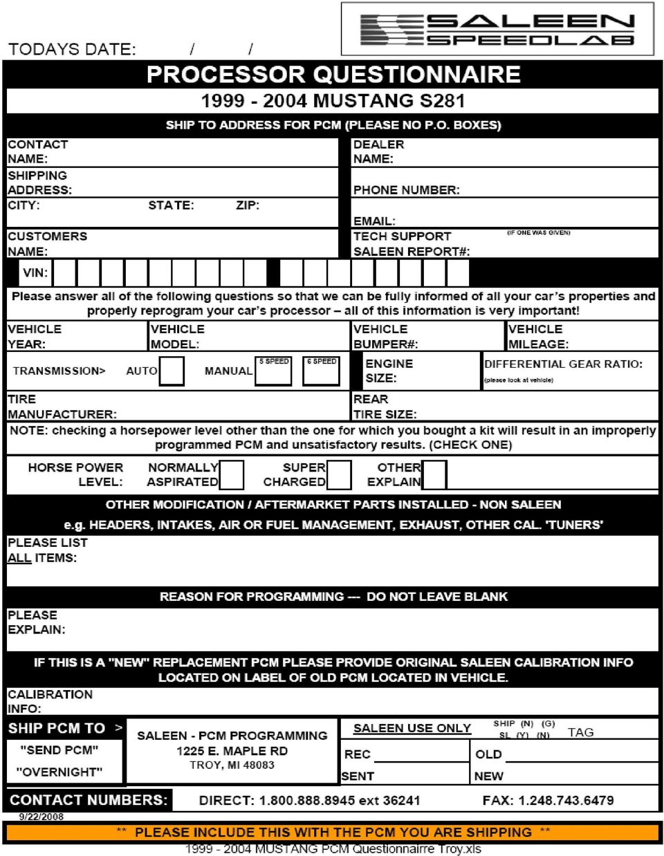
4 Removing the Processor 1. Open the passenger s side door and lift up the door sill plate (figure 1), it just pulls straight up. Remove the Christmas tree fastener at the front of the passenger s side kick panel and lift the panel out. 2. Unbolt the connector bracket in front of the processor. There are two bolts that hold the bracket in, one is through the hole in the carpet near the front of the foot well. You ll need a 7mm socket and 6 extension to remove them. 3. After moving the bracket outward, remove the bolt holding the large connector to the processor using a 10mm socket. Next remove the bolt in the lower rear corner of the white plastic processor hold down bracket. You will need a 5.5mm socket and 6 extension to reach it. It may be easier to remove the connector bolt after removing the processor hold down bracket. Now rotate the processor clockwise and out to remove it from the car. 4. Fill out the questionnaire. Figure 1 5. Place the processor and the questionnaire in the supplied prepaid FedEx box. This includes insurance for your processor. Saleen cannot reprogram your computer without the questionnaire being filled out and returned with the processor. 6. Deposit at any FedEx office or drop box. 7. Saleen will reprogram your computer and return it to you by FedEx within 2 business days of receipt.

5
6 Removing the Manifold 1. Disconnect the negative battery terminal using an 8mm wrench. 2. Drain the coolant from the radiator by opening the valve on the passenger s side bottom of the radiator using a 19mm wrench. Warning: Radiator fluid tastes very sweet to children and pets AND IT IS DEADLY. Please dispose of carefully or filter and reuse. 3. Disconnect the mass air sensor connector by pressing on the tab and pulling (figure 2). 4. Disconnect the air charge temperature sensor connector by pressing on the tab and pulling (figure 2). 5. Remove air inlet tube between mass air and throttle body by loosening the clamps at either end with an 8mm wrench and pulling out the other hoses going into it. Save this part. 6. Remove spring retainer (safety clip) from fuel feed line. 7. Disconnect the fuel feed line using a 5/8 Ford quick connect tool (figure 3). 8. Remove the throttle return spring from the throttle body and save it. 9. Disconnect cruise control cable from throttle body using a small flat blade screwdriver. 10. Open throttle body all of the way to loosen the throttle cable enough to slip it off the cam and out of its holder. 11. Remove throttle linkage bracket using a 10mm wrench and tuck the cables out of the way behind the master cylinder. Save the bracket. 12. Disconnect the coolant temperature sensor connector by pressing on the tab and pulling. The sensor is located on top of the manifold next to the alternator. 13. Disconnect the 8 fuel injectors by pressing in the tabs on either side of the connector. 14. Remove the 8 bolts holding the coils with a 7mm socket and a 6 extension. 15. The coils can be lifted out and hung to the side. 16. Disconnect the fuel rail pressure sensor connector by pressing the tab on the connector. The sensor is located on the fuel rail between cylinders 6 and Disconnect the vacuum lines that run to the fuel pressure sensor. 18. Disconnect the EGR solenoid connector by pressing on the tab (figure 4). 19. Remove the vacuum lines running to the EGR solenoid (figure 4). 20. Disconnect the vacuum lines from the EGR valve (figure 5). Figure 2 Figure 3 Figure 4 Figure 5
. 4. Disconnect the air charge temperature sensor connector by pressing on the tab and pulling (figure 2). 5.")
7 21. Pull off the ground wire from the fuel rail hold down bolt at the driver s side rear of the fuel rail next to the EGR solenoid. 22. Disconnect the idle speed control valve connector by pressing the tab on the connector (figure 6). 23. Remove the vacuum lines from the throttle body (figure 6). 24. Disconnect the throttle position sensor by pressing the tab on the connector (figure 6). 25. Remove the PCV valve and tubing from the passenger s side valve cover and the silver throttle body assembly. You may need to use a flat bladed screwdriver to work the hose off at the throttle body assembly. Save this part. 26. Pull off the air inlet tube from the idle speed control valve and save the parts (figure 7). Figure Remove fresh air tube from valve cover (figure 8). 28. Disconnect the vacuum lines from the rear of the silver throttle body assembly. 29. Remove the PFE and EGR solenoid bracket using a 10mm socket and a 6 extension (figure 9). 30. Disconnect the PFE connector by pressing the tab on the connector (figure 9). 31. Disconnect the vacuum lines from the PFE valve. Please note that the valve is marked HI and REF. The REF port is connected to the upper port on the EGR tube and the HI port is connected to the lower port on the EGR tube. 32. Loosen the EGR tube at the manifold using a 27mm or adjustable wrench. Figure Disconnect the engine wiring harness from the manifold by pulling out the two Christmas tree fasteners at the rear of the manifold (figure 10). Figure Disconnect the alternator main power wire from the top of the alternator using a 10mm socket and extension. 35. Remove the alternator hold down bracket by removing the 4 bolts using an 8mm wrench. 36. Loosen the serpentine belt by moving the tensioner with a 1/2 drive socket wrench with a 1/2 to 3/8 adapter on it and remove the belt. 37. Loosen the two bolts on the lower front of the alternator Figure 9 with a 10mm socket. You do not have to remove the bolts, the alternator is slotted and will lift out once the bolts are loose. 38. Disconnect the connector on the back of the alternator by pressing the tab and pulling. 39. Remove EGR tube from exhaust pipe using a 25mm and a 27mm Figure 10

8 wrench. You will have to reach in through the gap between the engine frame ( K member) and the vehicle frame. 40. Remove the heater hose from the rear of the manifold using pliers to open up the hose clamp. Slide the hose clamp up the hose and release it to save it for later use. 41. Unbolt the noise suppresser from the thermostat housing bolt by removing the nut with a 10mm socket and move it out of the way. 42. Unbolt the noise suppresser from the passenger s side front of the manifold by removing the nut with a 10mm socket and move it out of the way. 43. Remove the hose from the thermostat housing using pliers to open up the hose clamp. Slide the clamp up the hose and leave it there for later use. You may need to slide a flat blade screwdriver in between the hose and the housing to loosen it for easier removal. 44. Remove the thermostat housing by removing the two bolts with a 13mm socket and extension. Be careful, there is an o ring gasket inside the housing that you will need. Save the gasket and the thermostat. You will not need the housing. 45. Remove the throttle body from the manifold using a 8mm wrench on the 4 retaining bolts. Save the gasket and the throttle body. 46. Remove the bolt at the passenger s side front of the manifold with a 13mm socket and extension. 47. Remove the 8 remaining manifold bolts with a 10mm socket and 6 extension. 48. Remove the manifold. Use duct tape to cover the intake holes in the head to keep out dirt and foreign objects during the next steps. 49. Remove the water pipe from the valley of the engine by first removing the water hose at the rear using pliers to open up the clamp. Slide the clamp up the hose to save for later use. Now unbolt the tube from the rear of the block using a 13mm box open wrench. Pull the tube from the front of the block (figure 11). You will not need the tube, but save the bolt. Preparing for the New Manifold Installation Figure Remove one of the Ford fuel rail hold down bolts (it also has a stud sticking out of it) using an 8mm deep well socket and screw it into the rearmost hole on the driver s side of the Saleen manifold (figure 12). 51. Remove the fuel pressure sensor from the Ford fuel rail with a 7mm socket and 3 extension. It is located on the fuel rail midway up the driver s side. Inspect the o rings on the sensor. We have found several of them to be damaged at the factory. You can get replacement o rings from an industrial hardware store. The part number is AS-568A-011 (.301 x.070). Make sure to get Nitrile or Buna-N materials as they are Figure 12 fuel resistant. Fuel resistance can be checked by submersing in a cup of fuel for several hours. The material should not swell too much and should retain flexibility. Install the sensor onto the Saleen fuel rail and tighten the bolts to 15 lb-ft.

9 52. Put the previously saved thermostat and o ring into the hole on the driver s side front of the Saleen manifold. The spring on the thermostat goes down and the o ring goes on top of the thermostat. 53. Remove the EGR solenoid from the previously removed bracket (figure 13). You ll need an 8mm, 3 extension and a 7mm wrench. Save the bolts and the nut. 54. Install the EGR solenoid onto driver s side rear fuel rail bolt (figure 14). Figure If you ordered the optional boost gage Figure 13 kit, install the sensor at this time. You ll need to remove the plug from the rear manifold plate and install the supplied 45o fitting using an adjustable wrench. Use thread sealant on the fitting and tighten until snug. Leave the fitting pointing up. Screw the sending unit into the fitting. Attach a 5 section of wire to the sending unit and tie it up out of the way. 56. Remove the PFE sensor from the previously removed bracket (it also held the EGR solenoid) using an 8mm deep well socket. Save the nut. Install the supplied PFE mounting bracket with the supplied 10mm bolt and a 16mm wrench. The bolt goes in the topmost hole on the back of the driver s side head just above the manifold Figure 15 mounting surface and below the valve cover. Install the PFE sensor onto the bracket using the saved M5 nuts and an 8mm deep well socket. The connector on the PFE sensor will face forward (figure 15). 57. Slide the supplied water tube onto the nipple at the front of the engine valley being careful not to damaged the O rings. Rotate the tube into place and reinstall the previously saved stock bolt. The bolt goes into the lower bolt hole on the back of the driver s side head (figure 15). You ll need a 13mm wrench. 58. Remove the hoses and heat shield sleeve from the stock EGR tube and put it on the new EGR tube. Note: you ll have to pull quite hard while twisting to remove the hoses. Don t use a screwdriver under to hose to pry it loose, they tear very easily. If you must cut them off, save as much length as possible. Cut 4 off of the heat shield sleeve and slide it over the curved end of the tube. Install the hoses onto the new tube putting the Figure 16 longer of the two hoses onto the angled port (figure 16). Slide the tube between the firewall and the rear of the driver s side head with the curved end up. Attach the tube to the exhaust pipe loosely so there is enough freedom to allow the manifold to slip in underneath it. 59. Hook up the hoses from the EGR tube to the PFE sensor. The top hose runs through the hole in the PFE bracket and connects to the REF port on the PFE sensor. The lower hoses connects to the HI port (figure 15). 60. Remove the throttle cable from the firewall with an 8mm socket and a 6 extension.

10 61. Using a flat blade screwdriver, remove the throttle cable from the throttle pedal (figure 17 and 18). Slide the new cable into place and reinstall the bolts. The fitting is keyed so it will only go in one way. Reattach the cable to the throttle pedal. Figure If you have cruise control, unhook the clip holding the cruise control cable to the firewall using a flat blade screwdriver. After removing the driver s side front tire, remove the driver s side inner fender liner. You ll need to remove the two Philips head screws from the outer front and rear of the wheel well and Figure 17 pull the 6 Christmas tree fasteners. 4 of the trees point down, one up front and three in the rear, and 2 point outwards one in front of the shock and one behind. Pull the liner down and out. The cruise control unit mounts in the rear of the fender well. Press the tab on the black plastic cable head (figure 19) to allow the head to rotate and turn it counter clockwise to unlock it (figure 20). Push the cable down to release it from the motor and pull it out (figure 21). Install the new cable by wrapping it counter clockwise around the motor cam and put the head unit back onto the motor and rotate it clockwise to lock the tab into place. Make sure the cable does not have too much slack or it will interfere with the installation of the head unit. Removal of the cruise control unit may facilitate this step. To remove the unit you ll need an 8mm socket. Reinstall the inner liner and the tire assembly. Figure 19 Figure 20 Figure 21 Installation of the Saleen Manifold 63. It is strongly recommended that you replace the intake manifold gaskets regardless of vehicle mileage!!! The gasket is designed to conform to the shape of the stock manifold and once depressed will not seal well with the Saleen Manifold. Remove the tape from the manifold mating surfaces and put the intake gaskets back into place. Lift the Saleen manifold into place with the help of a friend by lifting at the supercharger s nose and inlet tube on the passenger side and from the EGR flange on the driver side. Make sure not to slide the manifold across the gaskets, they can be cut easily!!! You may have to lift the wiring harness at the rear of the engine to provide the clearance you need to fit. 64. Line up the boltholes in the manifold and insert the 9 supplied M8 flange head bolts. Install the Saleen thermostat housing and insert the saved stock bolts. Snug all of the bolts and then starting from the center, work your way outwards in a clockwise direction tightening all bolts to lb-ft using a

11 10mm socket for the thermostat housing, 12mm socket for the supplied M8 bolts, a 6 extension and a u-joint. 65. Plug the loose vacuum hose that runs from the T under the fuel rail into the port on the fuel rail pressure sensor located on the driver s side midway up the rail. 66. Plug in the electrical connection to the PFE valve. It is the gray 4-position connector on the wiring harness that runs across the back of the engine. NOTE: IF YOUR KIT CAME WITH A PLASTIC INLET TUBE, FOLLOW STEP 67. (PLASTIC.) IF YOUR KIT CAME WITH A METAL INLET TUBE, FOLLOW STEP 67. (METAL.) 67. (Plastic) Using a 10mm deep well socket and a 3 extension, remove the two bolts holding the EGR valve to the driver s side of the silver throttle body assembly. One of the bolts is also a stud, so you may need a box open wrench to remove it. Install the EGR valve onto the Saleen manifold, along with the supplied red EGR spacer and metal tubular sleeve. It goes on the inlet tube behind the supercharger. Install the components in the following order: The 1 st EGR gasket goes between the plastic inlet tube EGR flange, and the red phenolic EGR spacer. Next insert the tubular metal sleeve inside of the spacer counter boar such that the tube penetrates the plastic inlet tube. Now put the second gasket over the spacer, and last bolt the EGR valve over the entire sandwich of components using the supplied M8 bolts. Torque the bolts to 15 ft-lbs. You ll want to use a small amount of Loctite on each of the two bolts. 67. (Metal) Using a 10mm deep well socket and a 3 extension, remove the two bolts holding the EGR valve to the driver s side of the silver throttle body assembly. One of the bolts is also a stud, so you may need a box open wrench to remove it. Install the EGR valve onto the Saleen manifold. It goes on the inlet tube behind the supercharger. Use the two supplied M8 bolts, and torque them to ftlbs. 68. Screw the EGR tube into the EGR valve using a 27mm wrench. You may have to loosen the EGR valve to start the threads onto the tube. Once the threads are started, retighten the EGR valve before tightening the tube. Make sure the tube is tight, but do not over torque it. 69. Run the driver s side intercooler hose under the wiring harness at the rear of the engine. 70. Put the coils back into their holes and reinstall the stock bolts. Tighten to 10 lb-ft using a 7mm socket, 6 extension, a universal joint and a 7mm box-open wrench. 71. Plug in the injectors. 72. Plug the ground wire onto the stud on the fuel rail hold down bolt at the back of the passenger s side of the manifold. 73. Slide the tab of the driver s side noise suppresser over the stud on the thermostat housing bolt. Using the stock nut and a 10mm deep well socket, tighten the nut snugly onto the stud. 74. Plug in the connectors to the fuel pressure sensor (it is mounted on the driver s side fuel rail) and the EGR solenoid (it is mounted on the driver s side of the supercharger). 75. Slide the tab of the passenger s side noise suppresser over the extension on one of the valve cover hold down bolts. It does not need to be secured. 76. Remove the engine coolant temperature sensor from the Ford manifold using a 19mm wrench. It is the gold and gray sensor standing straight up on the passenger s side front of the manifold. Install the sensor on the Saleen manifold in approximately the same position. Use thread sealant on the threads and tighten until snug. 77. Plug the gray connector onto the ECT sensor standing up on the front of the passenger s side of the manifold.
 IF YOUR KIT CAME WITH A METAL INLET TUBE, FOLLOW STEP 67. (METAL.) 67.")
12 78. Remove the idle speed control valve from the front of the silver throttle body assembly on the Ford manifold with an 8mm socket and 6 extension. Install the valve onto the Saleen manifold using the new gasket supplied and tighten to 15 lb-ft. 79. Plug in the black 2 position connector into the IAC valve on the passenger s side above the number 1 coil. 80. Install the throttle body with the Ford logo up using the supplied gasket and the saved stock bolts. Use an 8mm socket and a 6 extension to tighten the bolts to 10 lb-ft. Plug the 4 position black connector into the throttle position sensor on the front side of the throttle body. 81. Connect the heater core hose (the short hose that comes out of the firewall) to the hose barb standing up at the back of the passenger s side of the manifold. Make sure that the passenger s side intercooler hose runs behind the heater hose. Slide the clamp down the hose and over the barbs with a pair of pliers (figure 22). 82. Push the fuel line onto the fuel rail until you hear a loud click. Reinstall the safety retainer (figure 23). 83. Cut 3 off of the large vacuum line that comes up from the passenger s side wheel well. Push the hose onto the center (large) hose barb on the vacuum tree at the back of the inlet tube. You may need to cut the wire tire that holds the wiring harness at the back of the manifold and pull the Figure 24 Christmas tree fasteners out of the firewall in order to install the hose. Push the Christmas tree fasteners back into the firewall after installing the hose. Figure Remove the tape from the vacuum harness (figure 24) and pull out the hose (figure 25). Pull off the big 3/8 size connector (figure 26), and remove the 135 o connector from the harness and install on the open end (figure 27). At the other end, remove the red hose from the connector (figure 28) and rotate it 180 o (figure 29) and push the red hose back into the connector. To ease in the insertion of the hoses, lube the hoses before inserting them into the connectors. Figure 23 Figure 25 Figure 26 Figure 28 Figure 29 Figure Install the 135 o connector to one of the 1/4 ports on the vacuum tree (figure 30). Route the vacuum line under the fuel line. Plug the single hose end into the EGR valve (the black dish like device facing straight up) and hook the double connector to the EGR solenoid mounted on the driver s side of the

13 supercharger. It will only go on one way (figure 31). Figure 30 Figure 31 Figure If you have cruise control, route the cable along the firewall and across the top of the inlet tube to the bracket. Put the cable into the bracket with the nipple through the bottom hole in the bracket into the inlet tube. Put the supplied M6 bolt into the other hole but do not tighten at this time (figure 32). 87. If you don t have cruise control, install the supplied dowel pin into the large, unthreaded hole and tap into place. Put the supplied M6 bolt into the other hole but don t tighten it at this time (figure 33). 88. Run the throttle cable through the hole in the bracket and install the supplied M5 bolt and nut and tighten with an 8mm socket, 6 extension and an 8mm wrench. Run the cable around the cam and insert the ball end into the hole in the cam (figure 34). Center the cable in the slot in the cam and tighten the throttle cable bracket bolt with a 10mm socket and 3 extension. Modify the throttle cable return spring by cutting 4 coils off and bending the spring to fit in the hole on the throttle body. 89. Snap the cruise control cable onto the ball on the cam by pushing it downwards. The length of the cable can be adjusted by removing the clip and sliding the cable in or out until the white mark is exposed by about 1/4 (figure 35). Figure 33 Figure 34 Figure Now that the throttle and cruise control cables are connected make sure that you get full throttle by having someone fully depress the throttle pedal and checking to see if the throttle plate has opened fully. Minor adjustments can be made by loosening and moving the bracket on the inlet tube.

14 91. Remove the rubber and hard plastic tubes from the PCV valve (figure 36). Cut an 8 piece of the supplied 3/8 hose and push it on the PCV valve. Remove the splice in the purge line or cut the purge line in an easily accessible spot near the back of the passenger side valve cover. The purge line is the large rubber vacuum line that runs from the center of the tree on the back of the manifold and disappears into the passenger side wheel well. Insert the supplied 3/8 T fitting into the purge line and connect it to the PCV valve (figure 37). Insert the PCV valve into the passenger s side valve cover. Figure 37 Figure You need to modify the large rubber air inlet hose to make it fit between the mass air sensor and the throttle body. Cut the hose as shown in figures 38 and 39 where indicated by the screwdriver. You ll need to grind the hose ribs off so you install the clamp at the throttle body end. Install the hose and tighten the clamps. The passenger s side intercooler hose, if equipped, runs under the air inlet tube. The tube can be difficult to install. We ve found the best way to install it is the put it on the mass air first and then to put it on the bottom of the throttle body and rotate the tube counterclockwise up into place. Figure 38 Figure Cut the ACT wiring harness about 4 from the connector (figure 40). Solder the supplied gray and gray/red wires to both ends to extend the connector. After soldering, wrap the lines with electrician s tape and plug the connector into the ACT sensor at the lower front of the manifold (figure 41). Figure Cut the thick, black/red wire that goes to the main post on the alternator (figure 42). Solder the supplied extension in between the connector and the harness. You ll have to trim back the rubber insulator on the wires before you insert them into the solder cups on the extension. Cover the solder cups with electrician s tape (figure 43). Figure 41 Figure 42
. Insert the PCV valve into the passenger s side valve cover. Figure 37 Figure 36 92.")
15 95. Install the alternator S brace removing the driver s side lower alternator bolt and putting the bolt through the brace and back into the hole. The threaded hole goes up with the ledge facing forward (figure 44). Note the position of the other alternator bolt. You may need to file the slot in the lower driver s side ear to get the bolt to fit through (figure 45). Figure Bolt on the extended alternator power lead to the red post on the alternator using a 10mm wrench. The wire must angle forward to clear the supercharger (figure 46). Connect the 3 position connector onto the alternator. Figure 44 Figure 45 Slide the alternator onto the bolt in the block and align the other ear with the hole in the S bracket (figure 47). Now assemble the pulley, bolt, spacer and washer (figure 48) and slide the bolt through the alternator to the S bracket. Make sure the washer goes between the bolt head and the pulley and that it is the small washer that isn t much larger than the metal center of the bearing. Tighten the bolts with a 10mm and a 17mm socket to 25 lb-ft. Now torque the lower S bracket bolt to 25 lb-ft with a 10mm socket and a 3 extension. Figure 46 Figure 47 Figure Remove the three power steering pump reservoir bolts with a 10mm socket. The power steering pump reservoir mounts on the front of the passenger s side of the engine. Slide the reservoir out of the way. Remove the bolt at the top of the bracket with a 13mm socket and 3 extension. Remove the two nuts holding the wiring loom onto the bracket with a 13mm socket and 3 extension. Behind the wiring loom bracket there are two bolts must be removed with a 13mm deepwell socket. Now you can remove the bracket from the car (figure 49). Now cut the bracket (figure 50) with a hacksaw and reinstall the bracket, wiring harness and reservoir. Torque all of the bolts and nuts to 25 lb-ft. Figure 49 Figure 50
.")
16 98. Install the drive belt following the belt routing indicated on the supplied drive belt label. You ll need a 1/2 ratchet wrench and a 1/2 to 3/8 adapter to move the tensioner. 99. Slide the upper radiator hose onto the thermostat housing and put the clamp into place with a large pair of pliers Swap the two hoses on the air bypass assembly (figure 51). Install the hose assembly between the air inlet tube and the IAC valve as shown in figure 52. Figure Cut off the engine vent hose as shown in figure 53, then insert the cut end of the short piece into the 90 o rubber elbow Figure 51 coming out of the top of the driver s side valve cover (figure 54). Put an 8 piece of the supplied 5/8 hose in between the two ends of the plastic hose and insert the other end into the air inlet tube. Figure 53 Figure Remove the black plastic upper radiator cover by removing the 4 plastic Philip s head screws and lifting the fasteners out. You may need to pry up under the head in order to get the screw to back out. If you purchased the optional twin gage pod, install the water temperature sending unit into the short fitting on the bottom of the intercooler expansion tank using thread sealant and a 19mm wrench. Put the hose fittings into the other two holes in the tank using a 22mm wrench (figure 55). Make sure that the O rings are in place between the tank and the nut on the fitting. Bolt the expansion tank to the upper radiator support using the two 6mm bolts saved from the stock throttle body cable bracket (figure 56). Tighten to 15 lb-ft with a 10mm socket. You ll need to gently bend the AC hose out of the way to install the expansion tank. Be very careful with the tube to keep from breaking it Hook the passenger s side intercooler hose to the upper Figure 55 fitting on the expansion tank and tighten with a 22 mm wrench Hang the support rod from the hole in the rear of the expansion tank. Use the supplied nut with the attached washer and tighten to 15 lb-ft with an 11mm deepwell socket. Make sure the bracket faces forward. Figure 56
.")
17 105. Steps 107 to 126 are for intercooled cars only Raise the vehicle in front and support it safely Drill two holes with a 3/16 drill bit where the expansion tank support rod hits the lower radiator support (figure 57) and install the 2 6mm body bolts with a 10mm socket and 6 extension. Torque these to 10 lb-ft Remove the passenger s side front wheel and inner fender liner. You ll need to remove the two Philips head screws from the outer front and rear of the wheel well and pull the 6 Christmas tree fasteners. 4 of the trees point down, one up front and three in the Figure 57 rear, and 2 point outwards one in front of the shock and one behind. Pull the liner down and out. We removed the front fascia to make the installation easier to photograph, but you don t need to do that Drill out the four mounting holes on the water pump with a 5/16 drill bit. At this time, make sure that the two Philip s heads screws holding the bracket to the pump are tight. Drill a 5/16 hole in the inner fender (figures 58 and 60). Install the bracket using an M8 bolt, nut and washer and a 13mm socket and 3 extension and a 13mm wrench. Put the washer and nut on the bracket side of the joint. Mark the bumper in two places (figure 59). Now remove the bracket and drill 5/16 holes where the marks are. Use one of the supplied 1/8 drill bits to make a pilot hole and slowly increase the size until you get to 5/16. You will want to use new or very good drill bits, the bumper is very hard!! You might also want to use some oil, motor oil will do, to cool the drill bit as you go. Mount the bracket with three 8mm bolts, nuts and washers. The rearward one mounts as before with the washer and nut against the bracket, but the front Figure 58 Figure 59 ones have the bolt going through the washer and bracket with the nuts inside the bumper. Tighten to 15 lb-ft with a 13mm socket, 3 extension and a 13mm wrench Install the two fittings on the water pump using a 1 1/8 wrench and tighten very snugly. Use thread sealant on the threads Mount the water pump to the bracket with 4 8mm bolts, large washers and nylock nuts. Put the bolts through the pump and put the washers and nuts on top of the bracket. Tighten to 15 lb-ft with a 13mm socket, 6 extension and a 13mm wrench (figure 60). Figure Trim the foam in front of the bumper with a knife until you have a 1/2 Figure 61 space in front of the bumper that is flush with the bumper surface (figure 61). The area should be centered on the bumper and the length of the heat exchanger. A serrated knife makes this job easier.

18 113. Remove the lower bolt for the hood latch bracket and install the heat exchanger support bracket (figure 62). Tighten the bolt to 15 lb-ft with an 8mm socket and 6 extension Put the heat exchanger in place under the lower radiator support with the fans on the passenger s side to the rear and loosely install the bolt for the lower heat exchanger support bracket with a 13mm socket, 3 extension and a 13mm wrench. This will hold the heat exchanger while you mark to 3 holes in the flange on the lower radiator support. Remove the heat exchanger. Drill out the three holes using the 9/64 drill provided. Once the drill has punched through, move the handle Figure 62 of the drill around in an approximately 6 circle to ream out the hole a little larger. Put the heat exchanger back into place with the support bracket bolt loosely installed. Using the self tapping screws and a long Philip s head screwdriver, screw the heat exchanger to the bumper. Make sure the screws seat tight. If they don t, use a new screw and open the hole up a bit more with the drill. Tighten the lower bolt to 15 lb-ft Trim the wind deflector at each end of the heat exchanger to clear the hose fittings (figure 63 and 64). Use a hack saw on the plastic and a serrated knife on the rubber. Figure 63 Figure Install the short pre-made water hose from the outlet on the pump to the inlet on the heat exchanger. Tighten snugly with a 22mm wrench. Following the routing (figure 65) keeps the hose away from the frame Install the long hose from the inlet of the pump to the outlet of the expansion tank. Follow the routing (figures 66 and 67). Figure 65 Figure 66 Figure 67

19 Figure 68 Figure Run the driver s side hose down behind the brake lines (figure 68), alongside the frame rail to the outlet of the heat exchanger (figure 69). Tighten snugly with a 22mm wrench Gather up the wires coming from the fans and tie-wrap them to the lower radiator support (figure 70) Using a 5mm socket and 3 extension, remove the connector from the CCRM located inside the passenger s side front wheel well (figure 71). Slice away 3-4 of tape on the wiring harness to expose the wires Tie-wrap the fan controller to the wiring harness (figure 72) Following the wiring diagram at the end of Figure 70 this manual, use the splice junctions to attach the wires from the fan controller to the CCRM wiring harness. First put the wire in the CCRM wiring harness through the connector, then insert the wire from the fan controller (figure 73) and squeeze the block together Figure 71 enough to close the clasp. The aluminum piece must pierce the insulation of both wires to make a connection 123. Reinstall the fender liner and wheel and lower the car back onto the ground. Figure 72 Figure Refill the coolant in the radiator with a 50% mix of water and coolant. You ll need to top it off again after the car has warmed up, or you can unscrew the ECT sensor to bleed out the air and reinstall it once the coolant rises to the top Reinstall the reprogrammed computer into the passenger s side kick panel Hook up the battery ground terminal. Tighten the bolt with an 8mm wrench.
. 122.")
20 127. Fill the intercooler expansion tank with the same mix as you put in the radiator and turn the key on to start the pump. It will take 10 seconds for the pump and fans to start. You ll need to prime the water pump which can be difficult. Try letting the pump run while you tap the hose that runs from the bottom of the expansion tank to the pump, or loosen the hose fitting at the pump on the same line to let the trapped air out. If those don t work, try blowing hard into the cap of the expansion tank to force the water into the pump Check for fuel leaks and if all looks well, start the engine and check for vacuum leaks. If the car runs but the idle cycles high to low, there is a vacuum leak and you ll need to find it before you re through. All superchargers and manifold assemblies are pressure checked at Saleen before they are shipped, so a leak is probably in one of the hoses you ran during the install. Spraying carburetor cleaner at various junction points should help find the leak (the idle will drop if the cleaner gets into the engine through a vacuum leak) Install the EO# Plaque on the back of the supercharger (figure 74). Figure 74

21 Technical Support If you have any questions, please call our technical support representatives at (949) Warranty All Saleen supercharger kits are warranted to be free from defects in manufacture and workmanship for a period of 12 months or 12,000 miles from the date of sale. The warranty is limited to repair or replacement at Saleen, Inc, exclusive option, of goods or merchandise involved. Warranty will not be honored for damage or malfunction due to improper installation, misuse, unauthorized repair or alterations, or externally induced physical damage. No warranty is made for any other claims for special, indirect or consequential damage (including, but not limited to, component removal or installation equipment down time, prospective profits or other economic loss) because of any defect deemed warrantable by Saleen, Inc. Any claim made under this limited warranty must be presented to Saleen, Inc. With valid proof of date of purchase by the end-user.
22 Water Pump and Fan Relay Controller The water pump and fan controller is wired into your Constant Control Relay Module (CCRM) which is located in the passenger side wheel well. Remove your Passenger side tire and wheel well cover and follow the wiring instructions for your model year. It is recommended that you splice and solder your wiring connections Yellow/Black from controller to Yellow/Black (YE/BK) at CCRM Yellow/Black from controller to Yellow/Black (YE/BK) at CCRM Green/Yellow from controller to Dark Green/Yellow (DG/YE) at CCRM Short Black wire from controller to Ground Long Black wire from controller to Negative lead (Black) of Fans Pink from controller to Positive lead (Pink or Orange) of Fans Brown from controller to Positive lead (Orange) of Pump Negative lead (Black) from Pump to Ground Yellow/Black from controller to Black/Orange (BK/O) at CCRM Yellow/Black from controller to Black/Orange (BK/O) at CCRM Green/Yellow from controller to Dark Green/Yellow (DG/YE) at CCRM Short Black wire from controller to Ground Long Black wire from controller to Negative lead (Black) of Fans Pink from controller to Positive lead (Pink or Orange) of Fans Brown from controller to Positive lead (Orange) of Pump Negative lead (Black) from Pump to Ground
23 Supercharger Gauge Pod Option Blue/Red to Pin 4 (LB/RD) Intercooler Boost LT LT GND GND 12V SEND 12V SEND White/Blue to Pin 12 (WH/LB) Black to Pin 1 (Black) Pink to Sender Violet to Sender 2001 Hardware list
24 I. Bag 1 9 Intake manifold bolts (step 64) II. Bag 2 12in. Conduit (step 96) 4in. Wire extension (step 96) 6in Heat shrink (step 96) 1 Idler pulley (step 96) 1 Idler pulley spacer (step 96) 1 Alternator mount bracket (step 95) 1 Idler pulley bolt (step 96) 1 3/4in washer (step 96) III. Bag 3 2 Fittings for water pump (step 109) 2 Fittings for over flow tank (step 102) IV. Bag 4 4 5/16x18 nuts and bolts (step 111) 4 1 in washers (step 111) 4 3/4in washers (step 111) 3 3/8 bolts and nuts (step 109) 5 Self tapping screw (step 114) 1 3/8 bolt and nut (step 114) 2 M6 self tapping bolts (step 107) 1 M6 nut (step 107) 1 Bracket (step 114) V. Bag 5 2 M5 bolts and nuts (step 54) 2 1/2in washers (step 57) 1 PFE bracket and bolt (step 60) 1 13mm bolt VI. Bag 6 1 Throttle cable (step 61) 1 Cruise control cable (step 64) 1 Throttle bracket (step 86) 6in 3/8 fuel hose (step 91) 3/8 Vacuum tee (step 91) 12in 5/8 hose (step 101) VII. Bag 7 5 Blue scotch lock connectors (step 121&122) 6 Blue butt connectors (step 122) 1 Small eyelet (step 122)
25 VIII. Bag 8 1 Grey wire 18in long (step 93) 1 Grey and black wire 18in long (step 93) 1 Yellow and white wire 1 Brown and white wire 1 Grey and red wire 1 Green and red wire 3 ft Small conduit IX. Bag 9 (Plastic Inlet only) 1 Throttle body gasket (step 80) 1 Idle control gasket (step 78) 2 EGR valve gaskets (step 67) 1 EGR spacer 1 EGR sleeve IX. Bag 9 (Metal Inlet only) 1 Throttle body gasket (step 80) 1 Idle control gasket (step 78) 1 EGR valve gaskets (step 67)
SALEEN SPEEDLAB SERIES VI STANDARD SC UPGRADE KIT
 SALEEN SPEEDLAB SERIES VI STANDARD SC UPGRADE KIT INSTALLATION MANUAL: 2005 MUSTANG 4.6 3V MANUAL P/N: 10-8002-C14338C SUPERCHARGER KIT P/N: 10-1607-B14083* Saleen Performance, Inc. 1225 East Maple Rd.,
Figure 2 The fan and shroud also needs to be removed for access to the four a/c compressor bolts and removal of the compressor from the top.
 Here are some pictures to show what s required when replacing the A/C compressor, expansion valve and receiver/drier on a 2001 Volvo V70. Even if you don t replace these A/C parts these pictures can help
A&A CORVETTE PERFORMANCE C6 BOOST & FUEL GAUGE INSTALLATION INSTRUCTIONS
 A&A CORVETTE PERFORMANCE C6 BOOST & FUEL GAUGE INSTALLATION INSTRUCTIONS 1. Check your gauges before you take them out of the packaging to make sure they are at 0 (zero) psi for both boost and fuel pressure.
REMOVAL AND INSTALLATION
 303-01C-1 REMOVAL AND INSTALLATION Engine Body On Special Tool(s) Adapter For 303-D043 303-D043-02 or equivalent Special Tool(s) 303-01C-1 Turbocharger Lifting Bracket 303-1266 Wrench, Fan Clutch Nut 303-214
Solstice/Sky Water Pump Replacement
 Solstice/Sky Water Pump Replacement The water pump on the Solstice/Sky is starting to need replacement on some vehicles. This guide will help in replacing the water pump while the engine is still in the
Cooling system components, removing and installing
 Engine BHW Cooling system components, removing and installing Page 1 / 24 19-1 Cooling system components, removing and installing Warning! When doing any repair work, especially in the engine compartment,
M-9000-ZX3 JRSC Focus Big Boost Upgrade Kit INSTALLATION INSTRUCTIONS
 Please contact the Tech Hot Line for the most current instruction information (586) 468-1356!!! PLEASE READ THE FOLLOWING INSTRUCTIONS CAREFULLY PRIOR TO INSTALLATION!!! INTRODUCTION: These instructions
INSTALL INSTRUCTIONS KK-C-HVAC-1 HVAC UNIT 2003-2014 CHEVROLET/GMC VANS FOR
 INSTALL INSTRUCTIONS KK-C-HVAC-1 HVAC UNIT 2003-2014 CHEVROLET/GMC VANS FOR (For NEW 2007 ALL WHITE KWIK-KITS ONLY) Warning do not attempt to install A/C units unless you are experienced with servicing
Katana Supercharger Installation Instructions Rev. E Page 1 of 23
 Katana Supercharger Installation Instructions Rev. E Page 1 of 23 READ FITTING INSTRUCTIONS IN FULL BEFORE INSTALLATION This article is sold without warranty expressed or implied. No warranty or representation
Important: Please read these instructions carefully and completely before starting the installation. TITAN Fuel Tanks
 TITAN pt. no.: 03 0000 0120 Important: Please read these instructions carefully and completely before starting the installation. TITAN Fuel Tanks INSTALLATION INSTRUCTIONS G e n e r a t i o n V Extended
FRONT BUMPER INSTALLATION INSTRUCTIONS 2007-2011 DODGE / MERCEDES SPRINTER
 Aluminess Products Inc 9402 Wheatlands Ct. #A Santee, CA 92071 619-449-9930 FRONT BUMPER INSTALLATION INSTRUCTIONS 2007-2011 DODGE / MERCEDES SPRINTER Please read before beginning Stainless steel hardware
Cooling system components, removing and installing
 Page 1 of 34 19-1 Cooling system components, removing and installing WARNING! The cooling system is pressurized when the engine is warm. When opening the expansion tank, wear gloves and other appropriate
MGB Chrome Bumper Conversion
 MGB Chrome Bumper Conversion Installation Instructions For 1974 1/2-1980 MGB This kit requires cutting, welding, and painting. Professional installation recommended. Note: Every MGB body is slightly different
TITAN Fuel Tanks. INSTALLATION INSTRUCTIONS G e n e r a t i o n V
 TITAN pt. no.: 02 0000 0143 Important: Please read these instructions carefully and completely before starting the installation. TITAN Fuel Tanks INSTALLATION INSTRUCTIONS G e n e r a t i o n V Extended
COOPER S PULLEY UPGRADE KIT INSTALLATION INSTRUCTIONS PART NUMBER NME5011
 COOPER S PULLEY UPGRADE KIT INSTALLATION INSTRUCTIONS PART NUMBER NME5011 Below are instructions for the Mini Mania Pulley Upgrade Kit, Part Number NME5011. Please take all necessary precautions for working
Equipped with AEM Dryflow Filter No Oil Required! INSTALLATION INSTRUCTIONS PART NUMBER 21-754DS. 2012-2015 BMW 335i 3.0L
 Equipped with AEM Dryflow Filter No Oil Required! INSTALLATION INSTRUCTIONS PART NUMBER 21-754DS 2012-2015 BMW 335i 3.0L 1 ITEM NO. PART NUMBER DESCRIPTION QTY. 1 21-2057DK AIR FILTER 1 2 9-0442 TUBE;
M-9424-463V Intake Manifold INSTALLATION INSTRUCTIONS
 Please visit www.fordracingparts.com for the most current instruction information!!! PLEASE READ ALL OF THE FOLLOWING INSTRUCTIONS CAREFULLY PRIOR TO INSTALLATION. AT ANY TIME YOU DO NOT UNDERSTAND THE
Range Road RR Series Semi-Automatic Firewood Processor. Crated Unit Assembly Manual
 Range Road RR Series Semi-Automatic Firewood Processor Crated Unit Assembly Manual 1 1) Undo 8-18mm x 19mm Nuts and bolts, 2 on each leg of top frame 2) Lift top of Metal crate off and move out of work
specializing in AIR CONDITIONING, PARTS AND SYSTEMS for your classic vehicle PERFECT FIT IN-DASH HEAT/ COOL/ DEFROST 1967-72 CHEVROLET PICKUP
 specializing in AIR CONDITIONING, PARTS AND SYSTEMS for your classic vehicle PERFECT FIT IN-DASH HEAT/ COOL/ DEFROST 1967-72 CHEVROLET PICKUP CONTROL & OPERATING INSTRUCTIONS The controls on your new Perfect
ENGINE FUEL FUEL FILTER... FUEL HEATER... INJECTOR... SUPPLY PUMP... COMMON RAIL... FUEL PRESSURE LIMITTER...
 FUEL FILTER............................ FUEL HEATER.......................... INJECTOR.............................. SUPPLY PUMP.......................... COMMON RAIL.......................... FUEL PRESSURE
ADDING AN ELECTRIC AUXILIARY FAN TO RADIATOR STACK ON 03 ALPINE COACH
 ADDING AN ELECTRIC AUXILIARY FAN TO RADIATOR STACK ON 03 ALPINE COACH The original design of the 03 Alpine Coaches (and perhaps other years as well) did not include any kind of engine fan engage mechanism
PERFECT FIT SERIES IN-DASH HEAT/ COOL/ DEFROST 1967 CHEVROLET IMPALA
 specializing in AIR CONDITIONING, PARTS AND SYSTEMS for your classic vehicle PERFECT FIT SERIES IN-DASH HEAT/ COOL/ DEFROST 1967 CHEVROLET IMPALA CONTROL & OPERATING INSTRUCTIONS The controls on your new
INSTALLATION INSTRUCTIONS. 6111 Air Spring Kit 2011+ Ford F250/F-350 Single Wheel 2WD 2011+ Ford F350 Dually 2WD IMPORTANT NOTES
 INSTALLATION INSTRUCTIONS 6111 Air Spring Kit 2011+ Ford F250/F-350 Single Wheel 2WD 2011+ Ford F350 Dually 2WD Thank you for purchasing a quality Hellwig Product. PLEASE READ THIS INSTRUCTION SHEET COMPLETELY
INSTALLATION INSTRUCTIONS. 6108 Air Spring Kit 2011+ Ford F250 Single Wheel 4WD 2011+ Ford F350 Dually 4WD (2011 F350 Single Wheel 4WD use p/n 6113)
") INSTALLATION INSTRUCTIONS 6108 Air Spring Kit 2011+ Ford F250 Single Wheel 4WD 2011+ Ford F350 Dually 4WD (2011 F350 Single Wheel 4WD use p/n 6113) Thank you for purchasing a quality Hellwig Product. PLEASE
INSTALLATION INSTRUCTIONS 6108 Air Spring Kit 2011+ Ford F250 Single Wheel 4WD 2011+ Ford F350 Dually 4WD (2011 F350 Single Wheel 4WD use p/n 6113) Thank you for purchasing a quality Hellwig Product. PLEASE
Installation instruction do88 Intercooler for Volvo S40 / V50 / C30
 Installation instruction do88 Intercooler for Volvo S40 / V50 / C30 This instruction shows how to replace the OEM intercooler with our performance intercooler. 2. 3. 1. 4. 5. Part number: ICM-170 6. At
INSIDE ENGINE COMPARTMENT TOYOTA AIR CONDITIONING ENGLISH EUROPE,GENERAL,AUSTRALIA
 INSIDE ENGINE COMPARTMENT TOYOTA AIR CONDITIONING ENGLISH EUROPE,GENERAL,AUSTRALIA INTRODUCTION IMPORTANT NOTICE This manual has been designed for technicians who are qualified and educated in the proper
Turbocharger system components, servicing
 21-1 Turbocharger system components, servicing Engine codes: AAZ, 1Z, AHU Observe rules of cleanliness Page 21-10 Turbocharger hoses and lines, connecting Page 21-11 WARNING! Do not re-use any fasteners
3. SEISCO PARTS & SERVICE REMOVAL AND REPAIR GUIDE
 4 3. SEISCO PARTS & SERVICE REMOVAL AND REPAIR GUIDE A. Changing the Control Board B. Replacing a Heating Element C. Thermistor Replacement D. High Limit Switch Replacement E. Level Detector Replacement
INSTALLATION INSTRUCTIONS
 INSTALLATION INSTRUCTIONS Application Outboards Faria 5 Gauge Set* Publication No. Description Part Number Honda Code PII53606A White faced, flat lens 06300-ZW5-010ZB 6315410 Issue Date Black faced, flat
2003 ACCORD - Automatic Transmission Removal
 2003 ACCORD - Automatic Transmission Removal Special Tools Required Engine support hanger, A and Reds AAR-T-12566 Engine hanger balancer bar VSB02C000019 Front subframe adapter VSB02C000016 These special
Front brakes (FN- 3), servicing
, servicing") j a t Front brakes (FN- 3), servicing 46-1 Front brakes, servicing Note: Install complete repair kit. After replacing brake pads and before moving vehicle, depress brake pedal several times firmly to properly
j a t Front brakes (FN- 3), servicing 46-1 Front brakes, servicing Note: Install complete repair kit. After replacing brake pads and before moving vehicle, depress brake pedal several times firmly to properly
http://waterheatertimer.org/troubleshoot-rheem-tankless-water-heater.html
 http://waterheatertimer.org/troubleshoot-rheem-tankless-water-heater.html TECHNICAL SERVICE DEPARTMENT Removal, Cleaning, & Reinstallation of the Burner Assembly For models 74 & GT199 Required tools -
Slide the new steering column shaft through the steering column from the driver compartment.
 Slide the new steering column shaft through the steering column from the driver compartment. Push the column shaft through the steering column until the machined end is out past the column lower bushing.
Juice Box Stages 1&2 135&335 Installation Guide 5/10/08
 Tools Required: 8mm socket or nut driver Small flat head screwdriver Electrical tape, masking tape, or shrink tube Pep talk: Although the install looks daunting at first, once you get the learning curve
PRODUCT: WASHER / WASHER-DRYER COMBO MODEL: AW 120 / AW 122 / AW 125 AWD 120 / AWD 121 / AWD 129
 PRODUCT: WASHER / WASHER-DRYER COMBO MODEL: The information included in this Splendide Repair Manual may change without notice. Please see our web site www.splendide.com/service/docs.html for updates,
www.servicechamp.com
 1-800-221-0216 Fax: 1-800-472-2281 www.servicechamp.com Service Champ Part 52081 Service Interval every 30,000 miles / Chevrolet 1992-2002 6.5 liter Description and Operation The fuel filter element separates
COOLING SYSTEM Section Page
 5 COOLING SYSTEM Section Page 5.1 COOLANT PRE-HEATER... 5-3 5.2 COOLANT PUMP NON-EGR ENGINE... 5-7 5.3 COOLANT PUMP EGR ENGINE... 5-13 5.4 FRONT CONNECTOR HOUSING NON-EGR ENGINE... 5-17 5.5 FRONT CONNECTOR
Before installation it is important to know what parts you have and what the capabilities of these parts are.
 INSTALLATION GUIDE Before installation it is important to know what parts you have and what the capabilities of these parts are. The Recon XZT is the smallest and most powerful gauge of its kind. With
Cooling system components, servicing
 19-1 Cooling system components, servicing WARNING! The cooling system is pressurized when the engine is warm. When opening the expansion tank, wear gloves and other appropriate protection, cover the cap
Intake Manifold: Service and Repair
 2000 Chevy Truck S10/T10 P/U 2WD L4-2.2L VIN 4 Copyright 2008, ALLDATA 9.90 Page 1 Intake Manifold: Service and Repair Removal Procedure 1. Disconnect the battery negative cable. Refer to Battery Replacement.
MGB Air Conditioning Installation Instructions For 1962-76 LHD cars w/supercharger
 MGB Air Conditioning Installation Instructions For 1962-76 LHD cars w/supercharger PART #363-405 MOSS MOTORS, LTD. 440 Rutherford St. P.O. Box 847 Goleta, CA 93117 1-800-667-7872 FAX 805-692-2525 www.mossmotors.com
with installation dynafact boost GAUGE this manual is for use with systems 64050-64054
 owners manual with installation instructions dynafact boost GAUGE this manual is for use with systems 64050-64054 GENERAL INSTALLATION PRACTICES This manual is an installation guide for all 1. Banks DynaFact
BUGGY SETUP GUIDE. Volume GOKARTSUSA GY6 150, CN250. Buggy Setup Guide
 BUGGY SETUP GUIDE Volume 1 GOKARTSUSA GY6 150, CN250 Buggy Setup Guide GY6 150, CN250 DUNE BUGGY Buggy Setup Guide GOKARTSUSA.COM 2000 Highway 50 S. Lake Tahoe, CA 96150 Phone 800.603.1437 2 Table of Contents
DR50 Hensim Dirt Runner 49cc Dirt Bike (VIN PREFIX LLCH or LUAH)
") Page 1 of 21 Product Information Baja Web > Product Information > Parts Lists > DIRTBIKE > DR50 Hensim Dirt Runner 49cc Dirt Bike (VIN PREFIX LLCH or LUAH) DR50 Hensim Dirt Runner 49cc Dirt Bike (VIN PREFIX
Page 1 of 21 Product Information Baja Web > Product Information > Parts Lists > DIRTBIKE > DR50 Hensim Dirt Runner 49cc Dirt Bike (VIN PREFIX LLCH or LUAH) DR50 Hensim Dirt Runner 49cc Dirt Bike (VIN PREFIX
Overview PARTS LIST. B. Lever mounting base C. Flush handle assembly D. Grey/Blue float stop E. Grey float (Full Flush) F. Flush valve washer
 F. Flush valve washer") Overview READ ENTIRE INSTRUCTIONS BEFORE STARTING INSTALLATION PARTS LIST A. Flush valve B. Lever mounting base C. Flush handle assembly D. Grey/Blue float stop E. Grey float (Full Flush) F. Flush valve
Overview READ ENTIRE INSTRUCTIONS BEFORE STARTING INSTALLATION PARTS LIST A. Flush valve B. Lever mounting base C. Flush handle assembly D. Grey/Blue float stop E. Grey float (Full Flush) F. Flush valve
KEYLESS ENTRY UPGRADE SECURITY SYSTEM for 2004 TOYOTA HIGHLANDER
 KEYLESS ENTRY UPGRADE SECURITY SYSTEM for 2004 TOYOTA HIGHLANDER DEALER SERVICE AND INSTALLATION MANUAL KIT NO. 00016-30915 Contents PARTS LIST... 2 PARTS ILLUSTRATIONS... 2 VEHICLE PREPARATION... 3 INSTALLING
For a simple splice connection look at figure 21. This basic type of splice can be used almost exclusively when hooking up your wiring.
 Page 1 of 10 IMPORTANT: Before starting installation, please be sure that all items which were supplied with the kit are accounted for. Note: These instructions are to be used in conjunction with the instructions
R O A D M A S T E R, I N C.
 R O A D M A S T E R, I N C. 11 10 20 12 4 18 19 1 2 13 16 ITEM QTY NAME MATERIAL 1...2... 1/2" x 3 1/2" BOLT... 350103-00 2...2... 1/2" x 2" BOLT... 350097-00 3...6... 1/2" x 1 1/2" BOLT... 350095-00 4...2...
INSTALLATION INSTRUCTIONS FOR 2006-2009 VW MK5
 CI100018 INSTALLATION INSTRUCTIONS FOR 2006-2009 VW MK5 Rabbit, Jetta 2.5L These instructions are applicable to vehicles equipped with either manual or automatic transmissions Thank you for choosing to
Volkswagen Jetta, Golf, GTI 1999, 2000 Brake System 46 Brakes - Mechanical Components (Page GR-46)
") 46 Brakes - Mechanical Components (Page GR-46) Front brakes Brake pads, removing and installing Brake pads, removing and installing FN 3 brake caliper, servicing FS III brake caliper, servicing Rear wheel
46 Brakes - Mechanical Components (Page GR-46) Front brakes Brake pads, removing and installing Brake pads, removing and installing FN 3 brake caliper, servicing FS III brake caliper, servicing Rear wheel
R O A D M A S T E R, I N C.
 R O A D M A S T E R, I N C. 6 28 1 2 "ā 1 2 " 4 8 ITEM QTY NAME PART # 1...4...1/2 x 1 1/4 BOLTS... 350094-00 2...4...1/2 LOCK WASHER... 350309-00 3...4...1/2 HEX NUT... 350258-00 4...2...SPACER PLATE...
VW GOLF Mk4 TDI FRONT MOUNTING INTERCOOLER INSTALLATION INSTRUCTIONS
 VW GOLF Mk4 TDI FRONT MOUNTING INTERCOOLER INSTALLATION INSTRUCTIONS Tools required: 10mm/13mm socket and 3/8 drive ratchet with extension Torx T20/25/30 screwdrivers or bits Phillips head screwdriver,
Cooling system components
 Page 1 / 33 19-1 Cooling system components Caution! When doing any repair work, especially in the engine compartment, pay attention to the following due to clearance issues: Route lines of all types (e.g.
This kit may void factory warranty please check with manufacturer.
 Mfg Company TM Thank you for purchasing a Sinister Manufacturing Company EGR delete kit. Precision manufactured using aircraft quality 304 stainless steel and billet aluminum; this EGR kit is designed
2011-14 F250 6 RADIUS ARM KIT
 92154000 Thank you for choosing Rough Country for your suspension needs. 2011-14 F250 6 RADIUS ARM KIT Rough Country recommends a certified technician installs this system. In addition to these instructions,
Volkswagen Jetta, Golf, GTI 1999, 2000 Brake System 47 Brakes - Hydraulic Components (Page GR-47)
") 47 Brakes - Hydraulic Components (Page GR-47) FS III front brake calipers, servicing Front brake caliper piston, removing and installing FN 3 front brake calipers, servicing Front caliper piston, removing
47 Brakes - Hydraulic Components (Page GR-47) FS III front brake calipers, servicing Front brake caliper piston, removing and installing FN 3 front brake calipers, servicing Front caliper piston, removing
Walbro 255lph Inline Fuel Pump Install Procedure
 Walbro 255lph Inline Fuel Pump Install Procedure Note: Instructions are based on a single in tank pump with under car OEM VW filter. Total install time for a qualified technician is approximately 2 hrs.
XL PREMIUM OIL COOLER KIT
 -J05 REV. 0-0-0 XL PREMIUM OIL COOLER KIT GENERAL Kit Number 0008 Models For model fitment information, see the P&A Retail Catalog or the Parts and Accessories section of www.harley-davidson.com (English
FOR ANY QUESTIONS, PLEASE CALL US @ 727.347.9915 M-F 8:00a.m.-8:00p.m. EST. REAR BRAKES 1 AEROSPACE COMPONENTS 727.347.9915
 REAR BRAKES 1 AEROSPACE COMPONENTS 727.347.9915 REAR BRAKES Before getting started, remove all stock braking components. Pre-assembly of parts: Clean the bolts and the threads in the hat with acetone.
AWE Tuning Air/Air Intercooler Kit for 2000-04 Audi 2.7T
 AWE Tuning Air/Air Intercooler Kit for 2000-04 Audi 2.7T Congratulations on your purchase of the AWE Tuning Intercoolers for your 2.7T Audi. Hundreds of hours of design and operational testing were spent
Installation instructions, accessories - Handsfree for cellular phone, system B, entry level
 XC90 Section Group Weight(Kg/Pounds) Year Month 3 39 0.5/1.1 2006 07 XC90 2003, XC90 2004 IMG-249663 Page 1 of 18 Required tools A0000162 A0000163 IMG-239664 M0000232 IMG-253123 IMG-252223 Page 2 of 18
STEERING SYSTEM - POWER
 STEERING SYSTEM - POWER 1990 Nissan 240SX 1990 STEERING Nissan - Power Rack & Pinion Axxess, Maxima, Pulsar NX, Sentra, Stanza, 240SX, 300ZX DESCRIPTION The power steering system consists of a rack and
Installation Guide 2010 BMW S1000RR Full Exhaust System
 Installation Guide 2010 BMW S1000RR Full Exhaust System!! THIS PRODUCT IS DESIGNED FOR USE IN CLOSED COURSE RACING AND IS NOT INTENDED FOR HIGHWAY USE!! Congratulations on the purchase of your new TaylorMade
INSTALLATION INSTRUCTIONS
 INSTALLATION INSTRUCTIONS Accessory Application Publications No. AII23628 2003 PILOT Issue Date MAY 2002 PARTS LIST Security System Kit (sold separately): P/N 08E51-S84-100 2 Remote controls Attachment
Sebring Timing Belt and Water Pump Replacement
 Sebring Timing Belt and Water Pump Replacement I was motivated to do this work because of a bearing growling sound emanating from the engine. It would grind at low rpms when the engine was cold and then
LIFT-505. BMF Lift Kit. Yamaha Drive Gas or Electric. Installation Instructions
 LIFT-505 BMF Lift Kit Yamaha Drive Gas or Electric Installation Instructions Contents of LIFT-505 Yamaha Drive BMF Lift Kit: a (1 ea.) BMF A-Arm Assembly b (1 ea.) Driver Side Shock Tower c (1 ea.) Passenger
BUILT-IN DISHWASHER INSTALLATION INSTRUCTIONS
 BUILT-IN DISHWASHER INSTALLATION INSTRUCTIONS PLEASE READ COMPLETE INSTRUCTIONS BEFORE YOU BEGIN LEAVE INSTALLATION INSTRUCTIONS AND USER'S GUIDE WITH OWNER ALL ELECTRIC WIRING AND PLUMBING MUST BE DONE
Firewall Cover Installation Instruction Sheet
 Firewall Cover Installation Instruction Sheet Please Read Carefully Our Firewall cover is designed to fit on the stock strut brace. If you have an aftermarket strut brace than it is you re responsibility
OVEN PARTS For Models:GSC308PJB05, GSC308PJQ05, GSC308PJT05, GSC308PJS05 (Black) (White) (Biscuit) (Black Stainless)
 (White) (Biscuit) (Black Stainless)") OVEN PARTS 30" BUILT IN ELECTRIC COMBO SENSOR/SC (GOLD LINE) 3 05 Litho In U.S.A. (cre) 1 Part No. Rev.A OVEN PARTS 1 Literature Parts 4455994 Installation Instructions Use & Care Guide 8300346 Microwave
OVEN PARTS 30" BUILT IN ELECTRIC COMBO SENSOR/SC (GOLD LINE) 3 05 Litho In U.S.A. (cre) 1 Part No. Rev.A OVEN PARTS 1 Literature Parts 4455994 Installation Instructions Use & Care Guide 8300346 Microwave
Installation Instructions 6028.801
 DAZZLE Installation Instructions 08.80 Spread Lavatory Faucet with Speed Connect Drain* Congratulations on purchasing your American Standard faucet with Speed Connect drain, a feature found only on American
GPS AutoSteer System Installation Manual
 GPS AutoSteer System Installation Manual Supported Vehicles John Deere Sprayers 4720 4630 4730 4830 AutoTrac Ready PN: 602-0227-01-A LEGAL DISCLAIMER Note: Read and follow ALL instructions in this manual
INSTALLATION INSTRUCTIONS
 INSTALLATION INSTRUCTIONS Accessory Application Publications No. AII 26327 2004 S2000 Issue Date OCT 2004 PARTS LIST Security System: P/N 08E51-S84-100 Attachment Kit: P/N 08E55-S2A-101 2 Remote controls
GENUINE PARTS INSTALLATION INSTRUCTIONS
 GENUINE PARTS INSTALLATION INSTRUCTIONS DESCRIPTION: Illuminated Kick Plate APPLICATION: Rogue (2011) PART NUMBER: 999G6 GX010 KIT CONTENTS: Item A B C G H QTY 1 1 1 D 1 E 1 F 3 15 6 Description Kick Plate,
TOYOTA TUNDRA 2015 Billet Grille w/led DRL
 TOYOTA TUNDRA 2015 Billet Grille w/led DRL Part Number: 00016-34088 Accessory Code: BG3000 Conflicts Models 1794 and Platinum Kit Contents Item # Quantity Reqd. Description 1 2 LED DRL 2 1 Driver Box 3
1/29/2008 DR50. Baja Motorsports Inc. P.O. Box 61150 Phoenix, AZ 85082 Toll Free: 888-863-2252 PART NUMBERS PRICES ARE SUBJECT TO CHANGE 1 of 45
 DR50 Toll Free: 888-863-2252 PART NUMBERS PRICES ARE SUBJECT TO CHANGE 1 of 45 CYLINDER & CYLINDER HEAD Part UPC Number Description Baja Description 1 DR50-001 842645074424 CYLINDER 1 1 2 DR50-002 842645074431
STEERING HANDLEBAR/FRONT WHEEL/ FRONT SHOCK ABSORBER
 14 14 STEERING HANDLEBAR/FRONT WHEEL/ SCHEMATIC DRAWING ------------------------------------------------- 14-1 SERVICE INFORMATION------------------------------------------------ 14-2 TROUBLESHOOTING-----------------------------------------------------
DR90. Baja Motorsports Inc. P.O. Box 61150 Phoenix, AZ 85082 Toll Free: 888-863-2252 PART NUMBERS AND PRICES ARE SUBJECT TO CHANGE 1 of 51
 DR90 Toll Free: 888-863-2252 PART NUMBERS AND PRICES ARE SUBJECT TO CHANGE 1 of 51 CYLINDER & CYLINDER HEAD 1 DR90-001 842645048166 CYLINDER 1 1 2 DR90-002 842645048173 GASKET, CYLINDER 1 1 3 DR90-003
INSTALLATION INSTRUCTIONS PART NUMBER:
 Equipped with AEM Dryflow Filter No Oil Required! INSTALLATION INSTRUCTIONS PART NUMBER: 21-475B (Blue Finish) 21-475C (Gun Metal Grey Finish) 21-475P (Vacuum Metalized Chrome-VMC) 21-475R (Red Finish)
GENUINE PARTS INSTALLATION INSTRUCTIONS
 GENUINE PARTS INSTALLATION INSTRUCTIONS 1. DESCRIPTION: Auto-Dimming Mirror Kit with Compass and HomeLink 2. APPLICATION: Titan 3. PART NUMBER: 999L1 WS000 4. KIT CONTENTS: Item Qty Description Service
Cooling system components, removing and installing
 Volkswagen Touareg 3.2 - Cooling system components, removing and installing Page 1 / 24 19-1 Cooling system components, removing and installing Warning! Hot steam may escape when opening expansion tank.
R O A D M A S T E R, I N C.
 R O A D M A S T E R, I N C. 11 7 6 1 2 10 13 8 ITEM QTY NAME PART # 1...2...1/2 x 5 1/2 BOLT...350108-00 2...4...1/2 x 1 3/4 BOLT...350096-00 3...6...1/2 LOCK WASHER...350309-00 4...6...1/2 HEX NUT...350258-00
R O A D M A S T E R, I N C.
 R O A D M A S T E R, I N C. MOUNTING BRACKET KIT 14 8 7 4 13 5 6 ITEM QTY NAME MATERIAL 1...6...1/2" x 2 1/2" BOLT... 350099-00 2...2...1/2" x 1 1/2" BOLT... 350095-00 3...8...1/2" LOCK WASHER... 350309-00
TABLE OF CONTENTS. I. TROUBLESHOOTING... 2 - Section 1.01: Common Problems/Solutions... 2
 BAL Accu-Slide System I. Table of Contents TABLE OF CONTENTS I. TROUBLESHOOTING... 2 - Section 1.01: Common Problems/Solutions... 2 II. GETTING STARTED... 5 - Section 2.01: Tools You Will Need... 5 - Section
The Ford Model A Water Pump
 The Ford Model A Water Pump George Washington Chapter, Inc. 3903 Old Lee Highway Fairfax, VA 22030 1 Table of Contents Introduction/Specifications.. 3 1. Water Pump Inspection and Removal. 4 a. Removal..
SECURITY SYSTEM SMART SIREN KIT
 -J00876 REV. 009-0-09 SECURITY SYSTEM SMART SIREN KIT GENERAL Kit Number 688-0 Models For model fitment information, see the P&A Retail Catalog or the Parts and Accessories section of www.harley-davidson.com
Installation Instructions 4508 4508S
 SYMPHONY Spread Lavatory Faucet with Speed Connect Drain Congratulations on purchasing your American Standard faucet with Speed Connect drain, a feature found only on American Standard faucets. Speed Connect
UB1 AIR CONDITIONING UNIT INSTALLATION INSTRUCTIONS
 UB1 AIR CONDITIONING UNIT INSTALLATION INSTRUCTIONS INSTALLATION INSTRUCTIONS: Carefully read these instructions before installing your new air-conditioner. AUSTRALIAN AUTOMOTIVE AIR AL00500054E 1 Table
P7100 PUMP INSTALLATION INSTRUCTIONS Diesel Care & Performance Inc
 P7100 PUMP INSTALLATION INSTRUCTIONS Diesel Care & Performance Inc Installation Timing Pin Location CAUTION: Before installing the injection pump, be sure that number 1 cylinder is at the Top Dead Center
Installation Instructions
 Installation Instructions For Use with PXPV230, PXPV265, PXPD230, and PXPD265 models Attention! - Please read these instructions completely before attempting installation. Always unplug the power supply
UNIVERSAL LUMBAR INSTALLATION INSTRUCTIONS
 UNIVERSAL LUMBAR INSTALLATION INSTRUCTIONS CONTENTS Parts List... 2 Parts Diagram... 2 Helpful Hints... 3 Installation... 4 Operation and Troubleshooting Guide... 6 Warranty Information... 8 Form #3132,
CONTENTS TOOLS REQUIRED: Ratchet 13mm Socket 10mm Socket Phillips Screwdriver Pliers Panel Removal Tool. Amp Installation
 CONTENTS 1EA. SUBWOOFER ASSEMBLY P/N RUWRANGLER 1EA. 200 WATT AMP/BRACKET ASSEMBLY P/N RM11JKBTL - Bracket P/N RE08BTL200R - Amp 1EA. POWER HARNESS P/N RHWRANGLERPWR 1EA. OVERLAY HARNESS P/N RHWRANGLER
VS Commodore LPG installation utilising an LPG Memcal and Apexus Quick-kit.
 VS Commodore LPG installation utilising an LPG Memcal and Apexus Quick-kit. Description of the components and operation LPG/Petrol changeover switch The LPG change-over switch is mounted in the instrument
46431x92A Garden Tractor (1998) Page 1 of 16 Body Chassis
 Page 1 of 16 Body Chassis") 46431x92A Garden Tractor (1998) Page 1 of 16 Body Chassis 46431x92A Garden Tractor (1998) Page 2 of 16 Body Chassis 1 092546E701 Bracket, Seat 2 091963 Z Plate Assembly, Switch 3 164X26 Spring, Compression
46431x92A Garden Tractor (1998) Page 1 of 16 Body Chassis 46431x92A Garden Tractor (1998) Page 2 of 16 Body Chassis 1 092546E701 Bracket, Seat 2 091963 Z Plate Assembly, Switch 3 164X26 Spring, Compression
Power Window/Power Lock Installation. To begin with you will need all the parts listed below:
 Power Window/Power Lock Installation To begin with you will need all the parts listed below: From Donor Fiero: Fiero power window regulators Power window motors (Generic GM type part) -motors are riveted
MGA Alternator Conversion
 MGA Alternator Conversion Installation Instructions For 1955 to 1962 MGA PART # 130-078 and #130-088 440 Rutherford St. P.O. Box 847 Goleta, CA 93117 1-800-667-7872 FAX 805-692-2525 www.mossmotors.com
TRANS-05, Torque Tube Removal, Rebuilding, and Installation
 TRANS-05, Torque Tube Removal, Rebuilding, and Installation Tools Metric Wrench Set Metric Socket Set Jack Stands (6 minimum) Floor Jack 8mm Cheesehead socket (also referred to as 12 point internal socket
INSTALLATION MANUAL MODEL RP-100
 INSTALLATION MANUAL FOR 24 VALVE 5.9L CUMMINS POWERED DODGE TRUCKS 2003 THROUGH 2004.5 MODEL RP-100 READ THESE INSTRUCTIONS THOROUGHLY BEFORE BEGINNING INSTALLATION 5400 BUSINESS 50 WEST SUITE 8 573 635-0555
BR150 Pmi Baja Reaction 150cc Go Kart (VIN PREFIX L4VM)
") Page 1 of 21 Product Information Baja Web > Product Information > Parts Lists > GOKART > BR150 Pmi Baja Reaction 150cc Go Kart (VIN PREFIX L4VM) BR150 Pmi Baja Reaction 150cc Go Kart (VIN PREFIX L4VM)
Page 1 of 21 Product Information Baja Web > Product Information > Parts Lists > GOKART > BR150 Pmi Baja Reaction 150cc Go Kart (VIN PREFIX L4VM) BR150 Pmi Baja Reaction 150cc Go Kart (VIN PREFIX L4VM)
TITAN Fuel Tanks. Extended Capacity Replacement Tank for Diesel Chevrolet / GMC Trucks
 Important: Please read these instructions carefully and completely before starting the installation. TITAN Fuel Tanks INSTALLATION INSTRUCTIONS G e n e r a t i o n V Extended Capacity Replacement Tank