Installation instructions, accessories - Handsfree for cellular phone, system B, entry level
|
|
|
- Patrick Hensley
- 8 years ago
- Views:
Transcription
1 XC90 Section Group Weight(Kg/Pounds) Year Month / XC , XC IMG Page 1 of 18

2 Required tools A A IMG M IMG IMG Page 2 of 18

3 IMG IMG Page 3 of 18
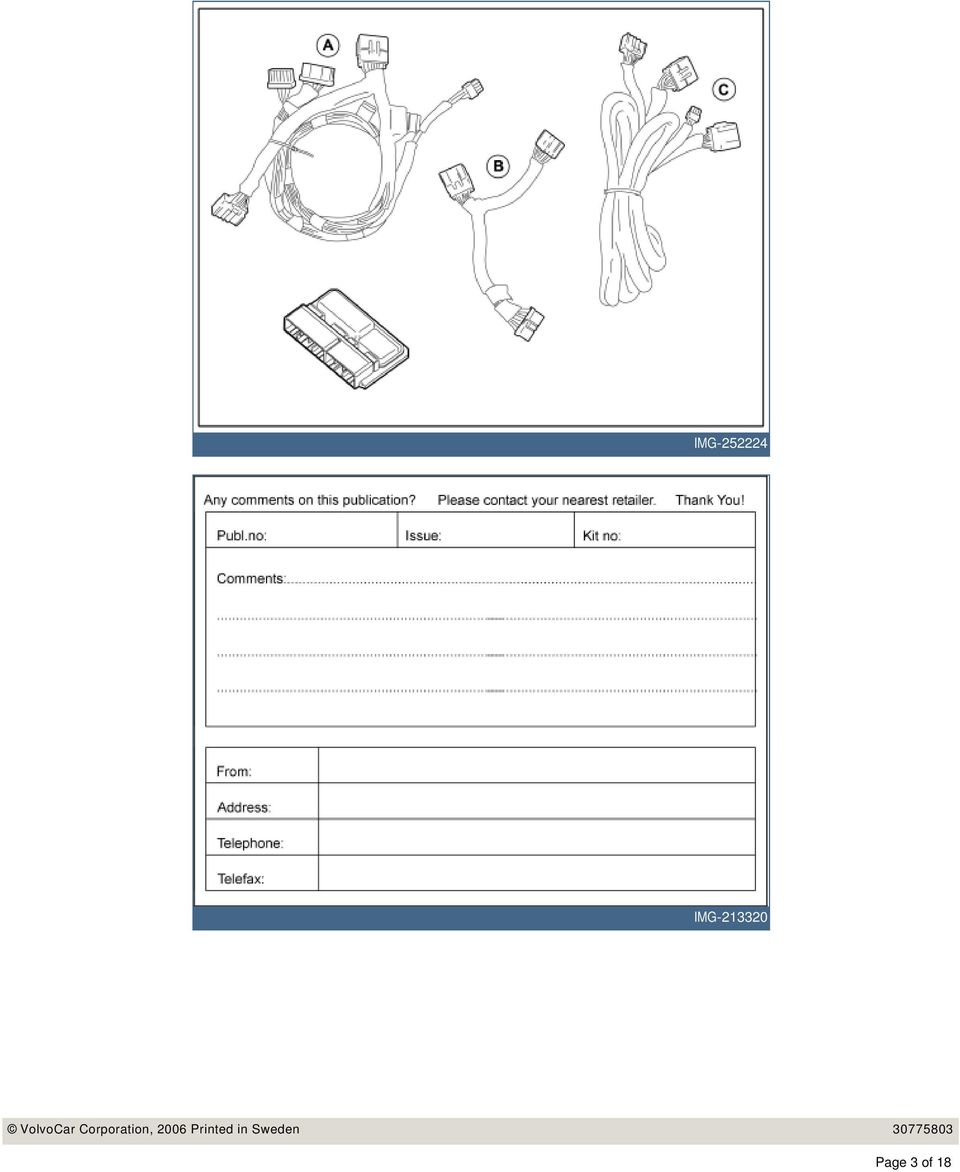
4 INTRODUCTION NOTE! Read through the entire text before carrying out any work. The front page gives the date of this edition and the edition it replaces Handsfree for cellular phone, system Note! These installation instructions show installation on a left-hand drive vehicle. When installing a right-hand drive vehicle, the procedures are reversed and/or carried out on the opposite side. Where the operations differ, right-hand versions are also shown. The second page shows the tools needed for the installation and the contents of the installation kit When installing antennas and Velcro tape, the underlying surface must be kept at a temperature of at least +20 C (68 F). The illustrations display the procedure in order of operation. The order of operation is repeated in the text section Wiring A is for vehicles with an internal amplifier that is located in the media player. Cut out the text page in order to follow the illustrations and text at the same time. Wiring B and C is for cars with an external amplifier, which is located under the right-hand front seat. Cars from and including model year -07 with audio system Performance Sound has an internal amplifier. Cars up to and including model year -06 with audio system Performance Sound has an external amplifier. Cars with the High Performance and Premium Sound audio systems have external amplifier. Page 4 of 18


5 1 Slide the right-hand seat all the way back and then completely upright at the front edge. Note! Also applies to right-hand drive cars Turn the ignition switch to position 0. A Disconnect the battery negative lead. Note! Wait at least three minutes before unplugging the connectors or removing other electrical equipment. 2 Removing the loudspeaker grille: Take a piece of welding rod Ø1.5 mm (1/16"). Bend it 90 at one end, L = 5 mm (13/64"). Bend the other end to make a handle. R First insert the bent end in the joint between the loudspeaker grille and the dashboard approximately as illustrated, until it engages. Turn the welding rod 90 so that the bent section catches the underneath of the loudspeaker grille. The welding rod may need moving along the joint to be turned. 3 Pull upwards until the loudspeaker grille detaches. It is securely fastened by four clips. Note! Do not damage the dashboard. Place the loudspeaker grille to one side. R Page 5 of 18

 Remove the five screws for the monitor.")
6 4 Remove the bracket for the loudspeaker grille by removing the five screws and pulling the grille up from the dashboard. Disconnect any connectors R Applies to cars with RTI (road traffic information) Remove the five screws for the monitor. Pull the monitor up slightly from the dashboard and disconnect the connectors. R Lower the steering wheel to its lowest position and then move it rearward to its rearmost position. Remove the two screws at the top edge of the combined instrument panel border. Carefully use a weatherstrip tool to pry loose the rubber seal from the upper steering wheel cover. It is held in place with five hooks. R Remove the border by carefully pulling it rearward - first at the bottom edge and then at the top edge - until all clips have released. 7 Remove the four screws for the combined instrument panel. Pull out the combined instrument panel. Disconnect the connector on the reverse of the combined instrument panel. R Page 6 of 18

7 8 Applies to cars with automatic gearbox Turn the ignition key to position II. Applies to all models Move the gear selector lever to its rearmost position. Carefully prize away the gear lever panel at the rear edge using a weatherstrip tool. R Press in the catches and remove the panel. IMG Remove the two screws. Remove the A/C / radio unit from the center console. Pull the bracket at the lower edge and then downwards until it releases from the mounting at the upper edge. Note! R Do not damage the removed components or the surrounding panels. Unplug the connectors. 11, telephone holder Take the telephone holder's bracket with reinforcement plate, cover and screws from the kit. Install the reinforcement plate (1) and cover (2) in the bracket (3) with screws (4) and screw (5). IMG Page 7 of 18

.")
8 12, telephone holder Place the entire unit (1) in the dashboard for marking the holes for the bracket. Adjust to achieve the best position. Do not press the unit hard against the dashboard but ensure that there are no gaps at the sides between the panel and dashboard (2). R , telephone holder Hold the unit securely and mark out the holes through the bracket. Drill out the two holes using a Ø 5 mm (13/64") drill bit. Use a 25 mm (1") drill stop. Remove any swarf. Remove the cover and reinforcement plate from the bracket. R , telephone holder Take the reinforcement plate (1) and two screws from the kit. Place the telephone holder's cables that are routed on the rear side of the bracket as illustrated. Insert the reinforcement plate through the hole for the central loudspeaker. M Install the bracket (2) with the two screws (3). Tighten the bracket to the end of the dashboard. 15, telephone holder Press the surround on to the combined instrument panel. Make markings on the surround as illustrated, where cut-outs are to be made for the wiring and the bracket for the handset holder. Remove the surround and file out the groove (1) for the cables for the handset holder. The groove must be large enough for any excess cable to be pulled through. R File out a groove (2) for the bracket for the handset holder. Smooth off the filed cut-outs. Page 8 of 18
 and two screws from the kit.")
9 16, telephone holder Route the cables from the mounting plate in the hole behind the combined instrument panel and continue to the center console. Do not route the cables in too much so that the mounting plate cannot be installed. IMG Pry off the rear edge of the panel on the left-hand end of the dashboard. Twist out the panel. Remove the panel. R Pry up the cover on the grab handle by the posts and remove the screws from underneath. Pull off the rubber strip in the door opening. R Pull off the A-pillar panel at the upper edge and then straight upwards to remove it. R Page 9 of 18

10 20 Use isopropanol to clean the inside of the windshield (as illustrated). IMG Take the antenna from the kit. Remove the protective film from the rear side. Position the antenna as illustrated and press it onto the windshield. Press securely so that the tape adheres. IMG Route the antenna cable along the A-post, down toward the dashboard and out toward the end. Secure the cable using three tie straps. Caution! IMG The inflatable curtain (IC) is located inside the A-pillar panel, it is important that the cable is not positioned on it. 23 Take the mounting plate from the kit and position it on the A post panel's upper end as illustrated. If the microphone is already on the mounting plate, remove it. The microphone is attached by mounting hooks along the long sides. Mark out and drill the holes for the mounting plate. Use a Ø3 mm (1/8") diameter drill bit. Remove any swarf. R Page 10 of 18
 is located inside the A-pillar panel, it is important that the cable is not positioned on it.")

11 24 Install the mounting plate on the A-post panel using two screws from the kit. Caution! The inflatable curtain (IC) is located inside the A-post panel. It is important to file off the screws securing the mounting plate if necessary, so that they just fit through the panel. R Check how much of the screws protrudes on the reverse. Unscrew the screws. File off the screws to the correct length. Reinstall the screws. 25 Press the microphone from the kit into place on the mounting plate. R Route the microphone cable on the inside of the A-post panel. Secure the cable using pieces of butyl tape. R Press the A post panel into place. Install the screws and tighten them to 10 Nm (7 lbf.ft.). Press the covers over the screws into place. Pull the microphone cable and antenna cable through the dashboard's left-hand end, into the compartment for the combined instrument panel and into the microphone bracket. R Secure the cable using pieces of butyl tape under the combined instrument panel. Page 11 of 18

 and cover (2) in the bracket (3). Use screw (4). Check that the upper right-hand holes are opposite each other.")
12 Connect the combined instrument panel and reinstall it. Reinstall the surround for the combined instrument panel and tighten. 28 Installing the telephone holder Install the reinforcement plate (1) and cover (2) in the bracket (3). Use screw (4). Check that the upper right-hand holes are opposite each other. Tighten the screw (4). Install the mounting plate (5) and tighten it with the screws (6). IMG Feed the excess of the cables into the dashboard. 29 Installing the telephone holder Install the telephone holder on the mounting plate. IMG Steps apply to cars with external amplifier Remove the center console's left and right-hand side panel by first pulling them away at the front edge and continue backwards until all the clips have released. R Page 12 of 18

13 31 Remove the sound proofing panel by first removing the two screws and then prying off the sound proofing panel at the top edge. R Locate the 4 pin, gray, pre-routed connector for the power supply. It comes from the thick cable harness under the dashboard on the right-hand side of the steering wheel IMG Take cable harness C (marked C in the kit image) from the kit. Connect it to the existing connector. The pre-routed connector is already connected on certain cars. Disconnect this and connect both the connectors from the new cable harness. Install the loose connectors on the car's existing cable harness using a tie strap, IMG Only applies to left-hand drive vehicles. Route the cable harness backwards and across through the center console. IMG Page 13 of 18

14 35 Slacken off the amplifier screws (1) under the right-hand front seat. Applies to right-hand drive cars steps must not be mirrored. R Lift out the amplifier. Use a weatherstrip to raise it from its recessed position. Place the amplifier upside down as illustrated. Disconnect the connector at the arrow. IMG Remove the left-hand seat piece. IMG Pull the cable, that is connected to the 4 pin connector, out from the center console, under the carpet to the amplifier. Applies to right-hand drive cars Route the cable that was connected to the 4-pin connector, on the right-hand side of the center console and then under the carpet to the amplifier. IMG Page 14 of 18

15 39 Take cable harness B (marked B in the kit image), the mute relay and 2 pieces of foam tape from the kit. Connect cable harness B and the pre-routed cable harness C to the mute relay. Wrap the foam tape around the mute relay. IMG Connect the connector that was disconnected from the amplifier to the connector on cable harness C. Connect the connector on cable harness C to the amplifier. Secure the connected connectors using a tie-strap. IMG Place the mute-relay under the front left corner in the recess. Reinstall the amplifier and tighten it with the screws. IMG Steps apply to cars with internal amplifier. Take cable harness A (marked A in the kit image), the mute relay and 2 pieces of foam tape from the kit Connect the connectors from the cable harness to the mute relay IMG Page 15 of 18

 to the short cable (2) from the telephone holder mounting plate.")
16 43 Place the relay with the cable harness at the rear edge of the opening on the center console. IMG Connect the antenna cable (1) to the short cable (2) from the telephone holder mounting plate. IMG Installing the handsfree control module Clean the surrounding areas, as illustrated, underneath the detached A/C / radio unit. Use isopropanol. IMG Installing the handsfree control module Take the control unit from the kit and clean in the locations as shown in the image. Use isopropanol. IMG Page 16 of 18

17 47 Installing the handsfree control module Take a Velcro strip and cut off two pieces of the same length. Press the pieces together. Cut off two pieces of the same length again at the center IMG Installing the handsfree control module Remove the protective backing tape from one side of the Velcro fasteners which were pressed together. Apply the Velcro strips on the control module and press. IMG Installing the handsfree control module Remove the remaining protective file on the Velcro strips, align and install the control module on the A/C / radio unit as illustrated. Press onto the control module so that the tape adheres. IMG Installing the handsfree control module Take the adapter wiring from the kit. Connect the connectors as illustrated. Adapter wiring (1) to the control module. The cable (2) from the microphone. IMG The cable (3) from the power supply and mute relay. The cable (4) from the telephone holder. Page 17 of 18

18 51 Installing the handsfree control module Place the connectors and excess wiring at the bottom of the center console and secure them using a tie strap. Check that they do not rub against the edges of the bracket. IMG Installing the handsfree control module Reinstall the A/C / radio unit by first hooking the upper edge into place. Then press upwards and angle in the lower section. At the same time check that the cables are not trapped. Reinstall the screws. R Installing the handsfree control module Reinstall: panel for gear selector. the end face panel for the dashboard. sound proofing. seat piece. IMG the side panels on the center console. Turn the ignition key to position II. Reconnect the battery negative lead. Page 18 of 18

Installation instructions, accessories - Navigation system, RTI
 XC90 Section Group Weight(Kg/Pounds) Year Month 3 393 4/8.8 2007 08 Page 1 of 20 Required tools A0000162 IMG-239667 IMG-239664 IMG-239980 IMG-242205 R8802817 R3905015 Page 2 of 20 R3903812 IMG-213320 Page
V70 2011. Installation instructions, accessories. Digital radio DAB. Volvo Car Corporation Gothenburg, Sweden. V70 (08-) 2011 Volvo Cars Europe
 2011 Volvo Cars Europe") Instruction No Version Part. No. 31266810 1.1 31266809 Digital radio DAB IMG-295623 Page 1 of 13 Equipment IMG-242205 A0000162 IMG-239664 IMG-285783 Page 2 of 13 IMG-213320 Page 3 of 13 INTRODUCTION Read
Instruction No Version Part. No. 31266810 1.1 31266809 Digital radio DAB IMG-295623 Page 1 of 13 Equipment IMG-242205 A0000162 IMG-239664 IMG-285783 Page 2 of 13 IMG-213320 Page 3 of 13 INTRODUCTION Read
Installation instructions, accessories. Cruise control. Volvo Car Corporation Gothenburg, Sweden. Instruction No Version Part. No. 30739998 1.
 Instruction No Version Part. No. 30739998 1.1 Cruise control Page 1 / 11 Equipment A0000162 A0000161 A0801178 D8802049 Page 2 / 11 M8802108 Page 3 / 11 IMG-223164 Page 4 / 11 IMG-213320 Page 5 / 11 INTRODUCTION
INSTALL/REMOVAL INSTRUCTIONS: WINDOW REGULATOR
 REMOVAL/INSTALL OF WINDOW REGULATOR (741-306) Honda Accord 2003 07 General Tech Tips: Use painter s tape rather than duct tape to secure window. It will not damage paint or leave sticky residue. A plastic
Installing RNS-E SAT NAV for Audi A4
 As one of the major options on the A4 you can get a DVD Satellite Navigation System call the RNS-E. With the help of ebay these sat nav systems are now available to by at a rough cost of 650 plus the cost
GENUINE PARTS INSTALLATION INSTRUCTIONS
 GENUINE PARTS INSTALLATION INSTRUCTIONS 1. DESCRIPTION: Auto-Dimming Mirror Kit with Compass and HomeLink 2. APPLICATION: Titan 3. PART NUMBER: 999L1 WS000 4. KIT CONTENTS: Item Qty Description Service
Installation instructions, accessories. Alarm, siren. Volvo Car Corporation Gothenburg, Sweden. Instruction No Version Part. No. 30633795 1.
 Instruction No Version Part. No. 30633795 1.0 Alarm, siren Page 1 / 12 Equipment A0000162 A0000161 A0801178 IMG-233902 Page 2 / 12 IMG-213320 Page 3 / 12 INTRODUCTION Read through all of the instructions
New method, replacement of window and window lift, front door
 SERVICE INFORMATION Number: 831-1646 Year: 1996 Month: Market: FEBRUARI ALL New method, replacement of window and window lift, front door Cars concerned All Saab 900 M94- Background A new method of removing
Instrument panel. Volkswagen Touareg - Instrument panel. Special tools, testers and auxiliary items required. Release lever T10039
 Volkswagen Touareg - Instrument panel Page 1 / 14 70-1 Instrument panel Tools Special tools, testers and auxiliary items required Release lever T10039 Instrument panel, removing and installing Removing
Installation instructions, accessories - Alarm siren
 XC90 Section Group Weight(Kg/Pounds) Year Month 3 36 2003 04 XC90 2003, XC90 2004, XC90 2005, XC90 2006, XC90 2007, XC90 2008, XC90 2009, XC90 2010 R3904364 Page 1 of 6 Required tools A0000162 A0000161
Installation of Rear View Camera in a 1995 Roadtrek 190 Popular
 Installation Instructions: 1995 Roadtrek Rear View Camera Page 1 Installation of Rear View Camera in a 1995 Roadtrek 190 Popular Introduction. In the fall of 2010 we investigated rear view cameras for
TOYOTA Tundra 2007 - BACK-UP CAMERA SYSTEM Preparation
 Preparation Part Number(s): PT233-34070, PT923-35070-11, PT923-35070-43 NOTE: Part number of this accessory may not be the same as part number shown. Back Up Monitor Kit Contents PT923-35070-11 / PT923-35070-43
GENUINE PARTS INSTALLATION INSTRUCTIONS
 GENUINE PARTS INSTALLATION INSTRUCTIONS DESCRIPTION: Illuminated Kick Plate APPLICATION: Rogue (2011) PART NUMBER: 999G6 GX010 KIT CONTENTS: Item A B C G H QTY 1 1 1 D 1 E 1 F 3 15 6 Description Kick Plate,
INSTALLATION INSTRUCTIONS
 INSTALLATION INSTRUCTIONS Accessory Application Publications No. XM RADIO SYSTEM 2003 ACCORD 4 DOOR AII 24378 Issue Date MARCH 2003 The XM Radio will not fit in a vehicle equipped with a rear entertainment
INSTALLATION INSTRUCTIONS
 Rear Vision System Tailgate Handle Camera Mirror Display 2004-2014 Ford F-150 and 2008-2015 Ford Super Duty (Kit part numbers 9002-9521) Kit Contents: Mirror Tailgate Handle with camera and harness Interior
EZ-Steer Assisted Steering System
 EZ-Steer Assisted Steering System Installation Instructions Platform Kit P/N 53059-54 Case IH CVX 1135 CVX 1145 CVX 1155 CVX 1170 CVX 1190 CVX 1195 CVX 135 CVX 145 CVX 155 CVX 175 CVX 195 New Holland TVT
INSTALLATION INSTRUCTIONS
 INSTALLATION INSTRUCTIONS Accessory Application Publications No. All 24393 ACCORD (DX, LX) SYSTEM 2-AND 4-DOOR Issue Date AUG 2002 PARTS LIST Security System Attachment (LX): P/N 08E55-SDA-100A Unit panel
INSTALL/REMOVAL INSTRUCTIONS: WINDOW LIFT MOTOR
 REMOVAL/INSTALL OF WINDOW LIFT MOTOR (742-273) Ford Expedition 1997 2002, Lincoln Navigator 1998 2002, Ford F-150 Super Crew Cab 2001 General Tech Tips: Use painter s tape rather than duct tape to secure
5 Mechanisms and accessories
 5 Mechanisms and accessories 51A SIDE OPENING ELEMENT MECHANISMS 52A NON-SIDE OPENING ELEMENT MECHANISMS 54A WINDOWS 55A EXTERIOR PROTECTION 56A EXTERIOR EQUIPMENT 57A INTERIOR EQUIPMENT X79 NOVEMBER 2009
430 Power/Electronics Replacement
 Replacing the main board WARNING Before proceeding, turn off the main power switch and unplug the power cord. Caution Make sure you are properly grounded with an ESD strap before continuing. The main printed
INSTALLATION INSTRUCTIONS
 INSTALLATION INSTRUCTIONS Accessory Application Publications No. AII 26327 2004 S2000 Issue Date OCT 2004 PARTS LIST Security System: P/N 08E51-S84-100 Attachment Kit: P/N 08E55-S2A-101 2 Remote controls
MGB Chrome Bumper Conversion
 MGB Chrome Bumper Conversion Installation Instructions For 1974 1/2-1980 MGB This kit requires cutting, welding, and painting. Professional installation recommended. Note: Every MGB body is slightly different
INSTALLATION INSTRUCTIONS
 INSTALLATION INSTRUCTIONS Accessory Application Publications No. ACCORD All 30209 2-AND 4-DOOR SYSTEM (VP, LX, SE) Issue Date AUG 2005 PARTS LIST Security System Attachment: P/N 08E55-SDA-100A Unit panel
HP Laser Jet 4200/4240/4250/4300/4350 Swing Plate
 HP Laser Jet 4200/4240/4250/4300/4350 Swing Plate 1 Swing Plate Assembly-RM1-0043 1 Swing Plate Kit-5851-2766 (RM1-0043 plus RM1-1091 gear) CAUTION: Fuser may be hot. Turn off printer, unplug it and allow
Trailblazer, Envoy, Rainier, Ascender
 6. After removing the trim plate bezel simply remove the four ¼ screws holding the instrument cluster in place. Pull the cluster out and unplug the single wiring harness connection in the back. Trailblazer,
- power windows - alarm system - electric door mirror control - door warning light - central locking - seat memory
 Door Wiring Harness Plug Connections Binder -, Electrics Vehicle Type: (86) Model Year: 7 (V) Concern: Door wiring harness plug connections X11 / X12. Information: The rubber boot for the door connector
5800 Temperature Sensor Cable Assembly
 5800 Temperature Sensor Cable Assembly Removal and Replacement Instruction Sheet #60-4702-070 Revision D, January 14, 2013 Overview The 5800 has two refrigeration temperature sensors, one attached to the
P150SC15. Designed for 2015 Ford F150 Super-Cab and Super-Crew vehicles without Sony System. 2015 Stillwater Designs P150SC15-A2-20150813
 P150SC15 Designed for 2015 Ford F150 Super-Cab and Super-Crew vehicles without Sony System Subwoofer Assembly Amplifier Assembly Amplifier Harness 2015 Stillwater Designs P150SC15-A2-20150813 M6 Bolt M6
Installation Instructions
 Installation Instructions For Use with PXPV230, PXPV265, PXPD230, and PXPD265 models Attention! - Please read these instructions completely before attempting installation. Always unplug the power supply
SECURITY SYSTEM SMART SIREN KIT
 -J00876 REV. 009-0-09 SECURITY SYSTEM SMART SIREN KIT GENERAL Kit Number 688-0 Models For model fitment information, see the P&A Retail Catalog or the Parts and Accessories section of www.harley-davidson.com
INSTALLATION INSTRUCTIONS
 INSTALLATION INSTRUCTIONS Accessory Application Publications No. AII23628 2003 PILOT Issue Date MAY 2002 PARTS LIST Security System Kit (sold separately): P/N 08E51-S84-100 2 Remote controls Attachment
Jeep Wrangler Diagnosis & Repair Manual Water Leaks
 Jeep Wrangler Diagnosis & Repair Manual Water Leaks Rev. A General Notes 1. This manual applies to all Jeep models: 2/4 door & Hard/Soft Top 2. Before testing the vehicle, perform a review of the top system.
KEYLESS ENTRY UPGRADE SECURITY SYSTEM for 2004 TOYOTA HIGHLANDER
 KEYLESS ENTRY UPGRADE SECURITY SYSTEM for 2004 TOYOTA HIGHLANDER DEALER SERVICE AND INSTALLATION MANUAL KIT NO. 00016-30915 Contents PARTS LIST... 2 PARTS ILLUSTRATIONS... 2 VEHICLE PREPARATION... 3 INSTALLING
Jeep Wrangler Diagnosis & Repair Manual Water Leaks
 Jeep Wrangler Diagnosis & Repair Manual Water Leaks Rev. A General Notes 1. This manual applies to all Jeep models: 2/4 door & Hard/Soft Top 2. Before testing the vehicle, perform a review of the top system.
GPS AutoSteer System Installation Manual
 GPS AutoSteer System Installation Manual Supported Vehicles John Deere Sprayers 4720 4630 4730 4830 AutoTrac Ready PN: 602-0227-01-A LEGAL DISCLAIMER Note: Read and follow ALL instructions in this manual
EasyNote TJ Series. Disassembly Manual
 EasyNote TJ Series Disassembly Manual CHAPTER3 Replacing notebook components Preventing static electricity discharge Preparing the work space Required tools Preparing the notebook Adding or replacing memory
AUTO TRANS DIAGNOSIS Article Text 1998 Volkswagen Passat This file passed thru Volkswagen Technical Site - http://volkswagen.msk.
 AUTO TRANS DIAGNOSIS Article Text 1998 Volkswagen Passat This file passed thru Volkswagen Technical Site - http://volkswagen.msk.ru ARTICLE BEGINNING 1997-98 AUTOMATIC TRANSMISSIONS Volkswagen Shift Interlock
Guide for Modified Assembly: Lightning McQueen. By: Collin Patterson, University of Delaware. Materials and Tools:
 Guide for Modified Assembly: Lightning McQueen By: Collin Patterson, University of Delaware Materials and Tools: PVC o 40 inches of 1 in diameter PVC o 25 inches of ¾ in PVC o 4 x 1 in elbows o 2 x ¾ in
Volkswagen Jetta, Golf, GTI 1999, 2000 Brake System 46 Brakes - Mechanical Components (Page GR-46)
") 46 Brakes - Mechanical Components (Page GR-46) Front brakes Brake pads, removing and installing Brake pads, removing and installing FN 3 brake caliper, servicing FS III brake caliper, servicing Rear wheel
46 Brakes - Mechanical Components (Page GR-46) Front brakes Brake pads, removing and installing Brake pads, removing and installing FN 3 brake caliper, servicing FS III brake caliper, servicing Rear wheel
Networkfleet 3500 Product Line Installation Guide
 Networkfleet 3500 Product Line Installation Guide Light/Medium Duty (L3500) Heavy Duty (H3500) Universal (U3500) www.networkcar.com/fleet Customer Care: (866) 227-7323 customercare@networkcar.com Table
WARNING! REQUIRED TOOLS & SUPPLIES: HIGH VOLTAGE
 INSTRUCTIONS Product: GEM Electric Motorcars Models: All Subject: Instructions for installing Stereo Accessory Estimated Completion Time:.75 Hours Parts: See Page # 7 REQUIRED TOOLS & SUPPLIES: (1) 3/8
Solstice/Sky Water Pump Replacement
 Solstice/Sky Water Pump Replacement The water pump on the Solstice/Sky is starting to need replacement on some vehicles. This guide will help in replacing the water pump while the engine is still in the
FRONT BUMPER INSTALLATION INSTRUCTIONS 2007-2011 DODGE / MERCEDES SPRINTER
 Aluminess Products Inc 9402 Wheatlands Ct. #A Santee, CA 92071 619-449-9930 FRONT BUMPER INSTALLATION INSTRUCTIONS 2007-2011 DODGE / MERCEDES SPRINTER Please read before beginning Stainless steel hardware
Service Guide. Gateway M275
 Service Guide Gateway M275 Contents Replacing Gateway M275 Components.................................... 1 Identifying the convertible tablet PC model...................................... 2 Identifying
EZ-Steer Assisted Steering System
 EZ-Steer Assisted Steering System Installation Instructions Platform Kit P/N 53059-21 Case IH Puma 165 Puma 180 Puma 195 Puma 210 New Holland T7030 T7040 T7050 T7060 Revision A June 2007 Part Number 53345-21-EU2
C5 Sound Deadening & Insulation Kit Interior Removal & Installation Instructions
 C5 Sound Deadening & Insulation Kit Interior Removal & Installation Instructions Ok, let's start with taking the radio bezel dash area off first. Here is what the OEM radio looks like... First you flip
ipad 2 GSM Headphone Jack & SIM Slot Replacement
 ipad 2 GSM Headphone Jack & SIM Slot Replacement Replace the Headphone jack/sim slot in your ipad 2 GSM. Written By: Walter Galan INTRODUCTION Use this guide to replace a broken headphone jack or SIM card
TOYOTA TACOMA 2008- HANDS FREE BLU LOGIC Preparation
 TOYOTA TACOMA 2008- HANDS FREE BLU LOGIC Preparation Part #: PT923-00112 Conflicts: JBL Audio, Factory Navigation NOTE: Part number of this accessory may not be the same as the part number shown. Kit Contents:
Front axle components, overview
 just a test. Front axle components, overview 40-1 General Information Load bearing components and parts of the suspension must not be welded or straightened. Vehicles without drive axle must not be moved,
Installing the Video Input and TV Tuner Cards in a Compact Computer or a Dual PCI-Slot Tower Computer
 Installing the Video Input and TV Tuner Cards in a Compact Computer or a Dual PCI-Slot Tower Computer This booklet describes how to install the video input and TV tuner cards in a compact Macintosh computer
INSTALLATION MANUAL INSIDE PASSENGER COMPARTMENT. HFC 134a FOR EUROPEAN SPEC. / GENERAL SPEC. AIR CONDITIONING ENGLISH
 HFC 134a Ozone Friendly Refrigerant FOR EUROPEAN SPEC. / GENERAL SPEC. AIR CONDITIONING ENGLISH AAAMU-60 / INSIDE PASSENGER COMPARTMENT INSTALLATION MANUAL 2000 (EUROPE) B.V.. All Rights Reserved. This
POWER LOCK KIT GENERAL INSTALLATION -J04427 REV. 2007-12-04. Kit Number. Models. Additional Parts Required. Kit Contents
 -J0 REV. 00--0 POWER LOCK KIT GENERAL Kit Number -0, 0-0 Models For model fitment information, please see the P&A Retail Catalog or the Parts and Accessories section of www.harleydavidson.com (English
Spurious diagnostic trouble codes in the airbag system (SRS)
") SERVICE INSTRUCTION Number: 850-2077 Year: 1999 Month: Market: FEBRUARY ALL Spurious diagnostic trouble codes in the airbag system (SRS) Cars affected Saab 9-5 4D M98-99 up to and including chassis number
SERVICE INSTRUCTION Number: 850-2077 Year: 1999 Month: Market: FEBRUARY ALL Spurious diagnostic trouble codes in the airbag system (SRS) Cars affected Saab 9-5 4D M98-99 up to and including chassis number
FL ADJUSTABLE RIDER BACKREST MOUNTING HARDWARE KIT
 -J070 REV. 0-0-0 FL ADJUSTABLE RIDER BACKREST MOUNTING HARDWARE KIT GENERAL Kit Number 9-09A Models For model fitment information, see the P&A Retail Catalog or the Parts and Accessories section of www.harley-davidson.com
DIRECTIONS FOR ASSEMBLING BASE & WALL CABINETS
 DIRECTIONS FOR ASSEMBLING BASE & WALL CABINETS TheRTAStore.com STEP 1: CLEAR A WORK SPACE Place your RTA cabinet panels on a smooth, scratch resistant surface in a large, open area. (Some people like to
CONTENTS TOOLS REQUIRED: Ratchet 13mm Socket 10mm Socket Phillips Screwdriver Pliers Panel Removal Tool. Amp Installation
 CONTENTS 1EA. SUBWOOFER ASSEMBLY P/N RUWRANGLER 1EA. 200 WATT AMP/BRACKET ASSEMBLY P/N RM11JKBTL - Bracket P/N RE08BTL200R - Amp 1EA. POWER HARNESS P/N RHWRANGLERPWR 1EA. OVERLAY HARNESS P/N RHWRANGLER
UNIVERSAL LUMBAR INSTALLATION INSTRUCTIONS
 UNIVERSAL LUMBAR INSTALLATION INSTRUCTIONS CONTENTS Parts List... 2 Parts Diagram... 2 Helpful Hints... 3 Installation... 4 Operation and Troubleshooting Guide... 6 Warranty Information... 8 Form #3132,
http://waterheatertimer.org/troubleshoot-rheem-tankless-water-heater.html
 http://waterheatertimer.org/troubleshoot-rheem-tankless-water-heater.html TECHNICAL SERVICE DEPARTMENT Removal, Cleaning, & Reinstallation of the Burner Assembly For models 74 & GT199 Required tools -
Parts and Accessories Installation Instructions
 Parts and Accessories Installation Instructions INFO 1 4 2 5 3 6 TONE SELET FM AM MODE MENU F 38 393 B Retrofit Kit On-board Monitor and Navigation System BMW 7 Series (E 38) These installation instructions
snom 370 Quick Installation Kurzanleitung VoIP Business Phone www.snom.com 2007 snom technology AG All rights reserved. Version 1.
 snom 370 VoIP Business Phone Quick Installation Kurzanleitung 2007 snom technology AG All rights reserved. Version 1.0 www.snom.com snom technology AG Gradestr. 46 D-12347 Berlin, Germany Note to the reader
R02GA. July 31, 2002. Dear Blue Bird Owner:
 R02GA July 31, 2002 Dear Blue Bird Owner: This notice is sent to you in accordance with the requirements of the National Traffic and Motor Vehicle Safety Act. Blue Bird Body Company has determined that
TOYOTA PRIUS 2010- HANDS FREE BLU LOGIC Preparation
 TOYOTA PRIUS 2010- HANDS FREE BLU LOGIC Preparation Part #: PT923-00111 Conflicts: JBL Audio, Factory Navigation NOTE: Part number of this accessory may not be the same as the part number shown. Kit Contents:
Windshield Wiper System
 Volkswagen Golf 5 - Windshield Wiper System Volkswagen Technical Site: http://volkswagen.msk.ru http://vwts.info Page 1 / 15 92-1 Windshield Wiper System General information The windshield wiper system
800-551-1943. HP Laser Jet 2400 Series Fixing Drive Side Plate Assembly Fixing Drive Side Plate Assembly- RM1-1500 page 1
 Fixing Drive Side Plate Assembly- RM1-1500 page 1 CAUTION: Fuser may be hot. Turn off printer, unplug it and allow it to sit for 20 to 30 minutes before performing these maintenance procedures. Fixing
2003 Audi A4. AUDI' '3.0L V6 - AVK Engine - A4 & A6
 Installation (A4) CAUTION: Before installation, ensure camshafts are aligned, crankshaft is locked in place and camshaft gear bolts are loose as described in removal procedures. When turning camshaft,
VW Jetta, Golf, New Beetle 1.9L TDi Unichip PnP Installation Instructions
 VW Jetta, Golf, New Beetle 1.9L TDi Unichip PnP Installation Instructions and Warranty Information Tools Required 10mm combination wrench, 13mm Socket (Jetta/Golf only), 3/8-inch or ¼-Inch drive ratchet,
Wiper Motor Marinco 2.5. Installation Instructions
 Wiper Motor Marinco 2.5 Installation Instructions Wiper Motor Marinco-2.5 The Marinco 2.5 Wiper Motor Offers the Following Features: Fully sealed base and housing which allows installation in outdoor wet
Written By: Walter Galan
 Installing iphone 4S Display Assembly Written By: Walter Galan TOOLS: Phillips 00 Screwdriver (1) Plastic Opening Tools (1) PARTS: iphone 4S Display Assembly (1) iphone 4 and 4S Screen Protector (1) Small
LIFT-505. BMF Lift Kit. Yamaha Drive Gas or Electric. Installation Instructions
 LIFT-505 BMF Lift Kit Yamaha Drive Gas or Electric Installation Instructions Contents of LIFT-505 Yamaha Drive BMF Lift Kit: a (1 ea.) BMF A-Arm Assembly b (1 ea.) Driver Side Shock Tower c (1 ea.) Passenger
Mazda CX7 2007-09 99-7508
 INSTALLATION INSTRUCTIONS FOR PART 99-7508 APPLICATIONS Mazda CX7 2007-09 99-7508 KIT FEATURES DIN Radio Provision with Pocket ISO Mount Radio Provision with Pocket Double DIN Mount Radio Provision Stacked
ALLDATA Online - 2006 Dodge Truck RAM 2500 Truck 2WD L6-5.9L DSL Turbo VI... Service and Repair
 Page 1 of 15 Home Account Contact ALLDATA Log Out Help PAUL REDEHOFT Select Vehicle New TSBs Technician's Reference Component Search: OK 2006 Dodge Truck RAM 2500 Truck 2WD L6-5.9L DSL Turbo VIN C Conversion
Installation instruction do88 Intercooler for Volvo S40 / V50 / C30
 Installation instruction do88 Intercooler for Volvo S40 / V50 / C30 This instruction shows how to replace the OEM intercooler with our performance intercooler. 2. 3. 1. 4. 5. Part number: ICM-170 6. At
Figure 2 The fan and shroud also needs to be removed for access to the four a/c compressor bolts and removal of the compressor from the top.
 Here are some pictures to show what s required when replacing the A/C compressor, expansion valve and receiver/drier on a 2001 Volvo V70. Even if you don t replace these A/C parts these pictures can help
OWNER S MANUAL. Permolock C3. Docking system for Power wheelchair in vehicle
 OWNER S MANUAL US Permolock C3 Docking system for Power wheelchair in vehicle How to contact Permobil Head Office of the Permobil group Permolock C3 Docking system for electric wheelchair in vehicle Produced
Volkswagen B3 Passat Manual Transmission 02A 34 Manual Transmission - Controls, Assembly (Page GR-34) 02A 5-speed. Gearshift cable/lever installing
 02A 5-speed. Gearshift cable/lever installing") 34 Manual Transmission - Controls, Assembly (Page GR-34) 02A 5-speed Gearshift cable/lever installing Gearshift housing repairing Gearshift lever repairing lever/relay lever, installing Gearshift mechanism
34 Manual Transmission - Controls, Assembly (Page GR-34) 02A 5-speed Gearshift cable/lever installing Gearshift housing repairing Gearshift lever repairing lever/relay lever, installing Gearshift mechanism
Navico-Northstar 2kW JRC Radar Package, Scanner Cable Removal and Replacement
 Navico-Northstar 2kW JRC Radar Package, Scanner Cable Removal and Replacement This work instruction describes the methods and means for which to remove and reinstall optional scanner cable configurations
VW GOLF Mk4 TDI FRONT MOUNTING INTERCOOLER INSTALLATION INSTRUCTIONS
 VW GOLF Mk4 TDI FRONT MOUNTING INTERCOOLER INSTALLATION INSTRUCTIONS Tools required: 10mm/13mm socket and 3/8 drive ratchet with extension Torx T20/25/30 screwdrivers or bits Phillips head screwdriver,
INSTALLATION INSTRUCTIONS
 INSTALLATION INSTRUCTIONS Accessory TRIM Application 2008 ACCORD 4-DOOR Publications No. AII 35362 Issue Date AUG 2007 PARTS LIST Steering Wheel Trim (Without Navigation) P/N 08Z13-TA0-100 Right steering
Rack installation instructions
 Rack installation instructions Review the documentation that comes with the rack cabinet for safety and cabling information. Before you install the server in a rack cabinet, review the following guidelines:
PRODUCT: WASHER / WASHER-DRYER COMBO MODEL: AW 120 / AW 122 / AW 125 AWD 120 / AWD 121 / AWD 129
 PRODUCT: WASHER / WASHER-DRYER COMBO MODEL: The information included in this Splendide Repair Manual may change without notice. Please see our web site www.splendide.com/service/docs.html for updates,
Go-kart for little race-drivers
 Go-kart for little race-drivers Drill and drive. Go-kart What it lacks in speed, it more than makes up for in fun: the go-kart will excite little race-drivers. 1 Introduction It s only a go-kart, but it
TOYOTA TUNDRA 2015 Billet Grille w/led DRL
 TOYOTA TUNDRA 2015 Billet Grille w/led DRL Part Number: 00016-34088 Accessory Code: BG3000 Conflicts Models 1794 and Platinum Kit Contents Item # Quantity Reqd. Description 1 2 LED DRL 2 1 Driver Box 3
CORNER FRIDGE REFRIGERATION UNIT INSTALLATION AND OPERATION INSTRUCTIONS
 CORNER FRIDGE REFRIGERATION UNIT INSTALLATION AND OPERATION INSTRUCTIONS D E F Y I N G C O N V E N T I O N Congratulations on your new Corner Fridge Your new corner fridge may have different functions
Installation Instructions: Electrical System for Towing Hitch... 3
 ... 3 Installation Instructions: Electrical System for Towing Hitch... 3 321 527 391 103-002 - 51/12 VW Polo A05 RHD Westfalia 321 525 300 143 VW Polo V RHD, 06/09-321 527 300 143 VW Polo V RHD, 06/09-4
Date: Order No.: Supersedes: Group:
 Installation Instructions Date: October 2005 Order No.: Supersedes: Group: 82 P-I-82.70/416B P-I-82.70/416A Update: Step 2, Section K, page 13; Step 1, second check, Section M, page 14 SUBJECT: MODEL 171.454/456/473
UB1 AIR CONDITIONING UNIT INSTALLATION INSTRUCTIONS
 UB1 AIR CONDITIONING UNIT INSTALLATION INSTRUCTIONS INSTALLATION INSTRUCTIONS: Carefully read these instructions before installing your new air-conditioner. AUSTRALIAN AUTOMOTIVE AIR AL00500054E 1 Table
SERVICE MANUAL. Corpus 3G. Seat system for electric wheelchair
 SERVICE MANUAL US Corpus 3G Seat system for electric wheelchair How to contact Permobil Head Office of the Permobil group Produced and published by Permobil AB, Sweden Version 4, 2014-07 Item No.: 205260-US-0
snom 320 VoIP Business Phone Quick Installation www.snom.com 2005 snom technology AG All rights reserved. Version 1.00
 snom 320 VoIP Business Phone Quick Installation 2005 snom technology AG All rights reserved. Version 1.00 www.snom.com snom technology AG Gradestr. 46 12347 Berlin, Germany Note to the reader This is a
A&A CORVETTE PERFORMANCE C6 BOOST & FUEL GAUGE INSTALLATION INSTRUCTIONS
 A&A CORVETTE PERFORMANCE C6 BOOST & FUEL GAUGE INSTALLATION INSTRUCTIONS 1. Check your gauges before you take them out of the packaging to make sure they are at 0 (zero) psi for both boost and fuel pressure.
REMOVE AND REPLACE AIR CONDITIONER. 170 Popular Dodge REMOVAL: AIR CONDITIONING Section 4 Page 1
 Section 4 Page 1 REMOVE AND REPLACE AIR CONDITIONER 170 Popular Dodge REMOVAL: 1. Turn main breaker to the OFF position. 2. Unplug Air conditioner unit. 3. Remove cabinet doors on either side of Air conditioner.
Windshield Wiper System
 Windshield Wiper System Page 1 / 17 92-1 Windshield Wiper System General information Caution! When disconnecting and reconnecting battery terminals, observe all applicable Notes and torque specifications,
BACKUP CAMERA JEEP COMMANDER/GRAND CHEROKEE
 BACKUP CAMERA 1 JEEP COMMANDER/GRAND CHEROKEE 2 Call Out Description Parts Quantity 1 Tie Wrap-Nylon 6.9" Supplied in kit 12 2 Camera, Rear View Supplied in kit 1 3 Camera Extension Harness Connector Supplied
Written By: Walter Galan
 ipad 2 GSM LCD Replacement Replace the LCD in your ipad 2 GSM. Written By: Walter Galan INTRODUCTION Use this guide to replace a broken LCD. TOOLS: iopener (1) Phillips #00 Screwdriver (1) Plastic Opening
AM/FM ANTENNA RELOCATION KIT
 -J0 REV. 008-09-0 AM/FM ANTENNA RELOCATION KIT GENERAL Kit Number 766-09 Models This kit is used to relocate a fender-mounted AM/FM antenna to a Detachable Tour-Pak on specific model motorcycles. For model
Post Mount Light Installation*
 Post Mount Light Installation* *For the general installation of most Post Mount Spotlights, many vehicles may need slight modifications to these instructions. You will need the following tools: High torque
Boxster. Technical Information. Service 3/99 9415. Litronic Retrofit Kit
 Litronic Retrofit Kit 9 3/99 9415 Binder - 9, Electrics This bulletin replaces bulletin Grp. 9, #3/99, dated 5-20-99. Vehicle Type: Model Year: Concern: Information: As of 1997 (V) Retrofitting Litronic
Written By: Walter Galan
 ipad 2 GSM Rear Camera Replacement Replace the rear camera in your ipad 2 GSM. Written By: Walter Galan INTRODUCTION Use this guide to replace a broken rear camera. TOOLS: ifixit Opening Picks set of 6
COMPONENTS IP 2 INSTRUMENT PANEL INSTRUMENT PANEL ASSEMBLY ASSIST GRIP RETAINER RH FRONT PILLAR GARNISH RH FRONT DOOR OPENING TRIM WEATHERSTRIP RH
 INSTRUMENT PANEL INSTRUMENT PANEL INSTRUMENT PANEL PRECAUTION 1 1. PRECAUTION FOR VEHICLE WITH SRS AIRBAG AND SEAT BELT PRETENSIONER (a) Some of these operations may affect the SRS airbag system. Read
INSIDE ENGINE COMPARTMENT TOYOTA AIR CONDITIONING ENGLISH EUROPE,GENERAL,AUSTRALIA
 INSIDE ENGINE COMPARTMENT TOYOTA AIR CONDITIONING ENGLISH EUROPE,GENERAL,AUSTRALIA INTRODUCTION IMPORTANT NOTICE This manual has been designed for technicians who are qualified and educated in the proper