Figure 1 (end) Updated document to corporate requirements Added text to Paragraph 2.4
|
|
|
- Dana Malone
- 9 years ago
- Views:
Transcription
1 This specification covers the requirements for application of ELCON Drawer Series Connectors: True Hot Plug, Blind Mating Mixed Signal and Power Connectors. These connectors are designed for use in pluggable wire to board applications of power supplies. The connectors are available in a variety of custom configurations. The pin side connector accepts pin contacts, and the socket side connector accepts socket contacts. The contact cavities on both sides of the connector are marked for circuit identification. The high power connectors are available with or without pre installed guide pins; mid and low power connectors are designed with molded in guide posts to ensure positive mating of connectors. The molded in pin protectors prevent damage to the contacts. These features (including the guide pin holes and guide post cavities) have chamfered edges for ease of mating. The connectors are designed for float mount and fixed mount applications to allow blind mating with misalignment. All connectors are also designed with standoffs to allow easy printed circuit (pc) board cleaning after soldering. The contacts accept wire sizes 24 through 1/0 AWG. Contact sizes 20, 16, and 12 are available in crimp type, and solder type terminations. In addition, contact size 12 is available in hot plug, specifically designed for current interruption capability. Contact size 0 and 4 is available in crimp type termination, internal thread and external thread for ring lug mounting and bus bar mounting. Pin contacts (except size 0 and 4) are available in three lengths: standard, pre mate, and post mate for flexibility in contact sequencing. The contacts contain an active element, or crown band, which ensures maximum surface contact area, allows even insertion and withdrawal forces, and provides shock and vibration resistance. The contacts are available in loose piece only. Only crimp type and threaded contacts are removable. When corresponding with Tyco Electronics Personnel, use the terminology provided in this specification to facilitate your inquiries for information. Basic terms and features of these connectors are provided in Figure 1. Figure 1 (cont d)

2 Figure 1 (end) Updated document to corporate requirements Added text to Paragraph 2.4

3 Product Part Number and Product Code D033 are representative numbers of the ELCON Drawer Series Connectors. Use of these numbers will identify the product line and expedite your inquiries through a service network established to help you obtain product and tooling information. Such information can be obtained through a local Tyco Electronics Representative or, after purchase, by calling the Product Information number at the bottom of page 1. Customer Drawings for product part numbers are available from the service network. If there is a conflict between the information contained in the Customer Drawings and this specification or with any other technical documentation supplied by Tyco Electronics, call Product Information at the number at the bottom of page 1. Design Objective provides expected product performance and test information. Workmanship Specification is a guide for evaluating installed connectors for conditions which effect the cosmetics and/or function of the connector. Manual is available upon request and can be used as a guide in soldering. This manual provides information on various flux types and characteristics along with commercial designations and flux removal procedures. A checklist is included in the manual as a guide for information on soldering problems. Instruction sheets (408 series) contain detailed assembly instructions and repair procedures for product and tooling. Documents available which pertain to this product are: Document Number Document Title Screw Machine Contacts and Application Tooling Insertion/Extraction Tools for ELCON Circular Contacts Crimp type contacts are made of copper alloy plated with silver or gold. Solder type contacts are made of brass or copper alloy plated with silver or gold. The crown band is made of copper alloy plated with gold over nickel. Hot plug contacts are made of copper alloy plated with gold. Connector housings are made of polyester, 30% glass filled, UL94 V. Prolonged exposure to ultraviolet light may deteriorate the chemical composition used in the connector material. The connectors should remain in the shipping containers until ready for use to prevent deformation to the contacts. The connectors should be used on a first in, first out basis to avoid storage contamination that could adversely affect signal transmissions. The shelf life is six months from date of shipment. Do not store connectors near any chemical listed below as they may cause stress corrosion cracking in the contacts. Alkalies Ammonia Citrates Phosphates Citrates Sulfur Compounds Amines Carbonates Nitrites Sulfur Nitrites Tartrates

4 The length of the pin contacts (except size 0 and 4), designated by standard, pre mate, and post mate, varies among contact sizes and applies to the portion of the contact that protrudes from the connector after insertion (socket length does not include depth of the connector standoff). Mating socket contacts accept all pin lengths of the same contact size. The length of pin and socket contacts, as described, are shown in Figure 2. Includes hot plug contacts Figure 2 Probe proof socket contacts size 0 are designed with a protective cap to provide additional probe proof protection along with the crown band. This cap must not be removed from the contact. See Figure 3. Some crimp type contacts feature a sight hole located on the side of the wire barrel or in the center of the inside of the wire barrel. See Figure 3. Crimp contacts are rear insertable and removeable. PC board tail are rear insertable and non removable. The connector contact cavities contain retention clips. The retention clip is an important feature in holding the crimped contact in the connector. When the contact is fully inserted, the retention clips engage the shoulder of the contact and prevent backing out during mating of the connector. Figure 3 The contacts will accept stranded wire sizes 24 through 1/0 AWG. Proper strip length is necessary to properly insert the wire into the contact. The strip length of the wire is shown in Figure 4.

5 Figure 4 Crimp contact to wire according to instructions packaged with applicable tooling. These requirements apply equally to the pin contact and the socket contact. The crimp applied to the wire barrel portion of the contact is the most compressed area and is most critical in ensuring optimum electrical and mechanical performance of the crimped contact. The wire insulation must not enter the contact wire barrel. The crimp height is controlled by proper use of MIL DTL crimp tooling. Refer to Section 5, TOOLING for tooling information. Crimped splices must hold the wire firmly and have a crimp pull out test value meeting that specified in Figure 5 (the test value is that of the smallest wire size used in the contact). Figure 5

6 After crimping, the conductor ends must be flush to the end of the wire barrel. In contacts having a sight hole, this can be verified by checking that the conductor ends are visible in the sight hole. See Figure 5. The effective crimp length is the area where the crimp pressure is applied over the length of the wire barrel. After crimping the wire to the contact, the contact must be chucked, and rotated a minimum of 360. The point of TIR (total indicator reading) measurement must not exceed the dimensions shown in Figure 6. Figure 6 Threaded guide posts should not exceed a torque limit of 1.7 N m [15 in. lb] Threaded contacts with M6 threading should not exceed a torque limit of 4.5 N m [40 in. lb] Threaded contacts with 1/4 20 threading should not exceed a torque limit of 6.8 N m [60 in. lb] Care must be taken to avoid interference between adjacent connectors and/or other components. There is no required spacing between connectors, however spacing may be dependent on variable hardware used and the clearance required for mating connectors. The pin side connector and socket side connector can be installed or removed from either the back or the front of the panel (front of the panel is recommended). Usually, the socket side connector is mounted in the cabinet (energized) panel, while the pin side connector is mounted in the drawer (passive) panel. Dimensions for mounting holes, guide pins (if applicable), and panel cutouts, and maximum panel thickness for rear mounting are shown in Figure 7. Normally an insertion tool is not required to insert contacts into connectors, but if the wire bundle is large or individual wires are fragile, using an insertion tool is recommended. Push contact straight into the contact cavity until it bottoms (an audible click). After inserting contact into connector, pull back lightly on the wire to ensure contact is fully seated. The contacts are rear insertable and rear releasable; an extraction tool is needed to disengage the connector retention clips and remove the contact from the back of the connector. Only crimp type and threaded contacts are removable. Refer to Section 5 for tooling information. The pc board material shall be glass epoxy (FR 4 or G 10). The pc board thickness range shall be 1.38 through 5.08 mm [.054 through.200 in.].
 measurement must not exceed the dimensions shown in Figure 6. Figure 6 Threaded guide posts should not exceed a torque limit of 1.7 N m [15 in.")
7 Maximum allowable bow of the pc board shall be 0.03 mm [.001 in.] over the length of the connector. The connector number one position must be aligned with the number one position board hole. When placing connectors on the pc board, make sure that the contact solder tails are aligned and started into the matching holes before seating the connector onto the pc board. Figure 7

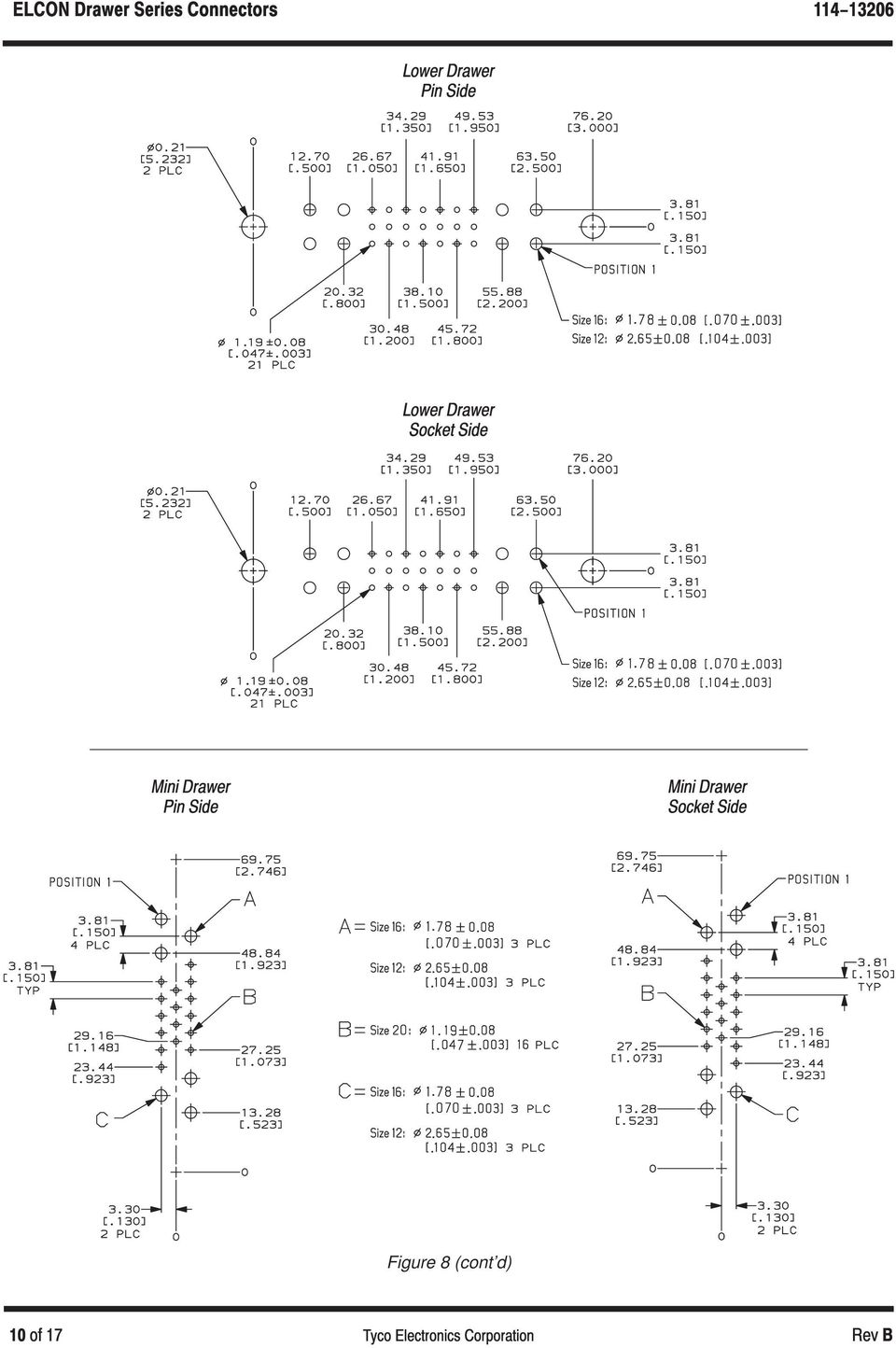
8 The mounting holes and contact holes in the pc board must be precisely located to ensure proper placement and optimum performance of the connector. Design the pc board using the dimensions provided in Figure 8. Figure 8 (cont d)

9 Figure 8 (cont d)

10 Figure 8 (cont d)
11 Figure 8 (end)

12 The solder type contacts may be used with or without plated through holes. If plated, the drilled hole size, plating types, and plating thickness are dependent on the application requirements. The finished hole size must be as stated to provide unrestricted insertion and ensure adequate application of solder to the solder tines. See Figure 9. ÉÉÉÉ ÉÉÉÉ ÇÇ ÉÉÉÉ ÇÇÉÉÉÉ Ç ÉÉÉÉ ÇÇÉÉÉÉ Ç ÉÉÉÉ ÇÇÉÉÉÉ Ç ÉÉÉÉÉÉ Ç ÉÉÉÉ ÉÉÉÉ Includes hot plug contacts Figure 9 The connector standoffs must be seated on the pc board or panel not exceeding the dimension shown in Figure 10. Figure 10 Observe guidelines and procedures when soldering contacts is required. All solder joints should conform to those specified in Workmanship Specification IPC A 610 and all other requirements specified in this document. Contacts must be stabilized during soldering with a non metallic material. Solder, clean, and dry all wire leads to contacts according to the following:

13 Wire lead and contact wire barrel interior shall be fluxed prior to soldering using a mildly active rosin. Flux must be compatible with manufacturing, safety, and health guidelines. After cleaning, removal of fluxes, residues, and activators is mandatory. Cleaning procedures and solvents depend on the type of flux used. See Figure 11. Figure 11 When drying cleaned connector assemblies, make certain that the recommended temperature limitations of 40 to +105 C [ 40 to +221 F] are not exceeded. Excessive temperatures may cause housing degradation. These connectors provide optimum mapping of pin to function, and ease of routing in the system by accepting various contact sizes, quantities, and types. All connector contact positions accept crimp type and solder type terminations. In addition, high power connectors accept threaded contacts (size 0 only). Possible contact options for loading individual connectors are shown in Figure 12. Figure 12
![Figure 11 When drying cleaned connector assemblies, make certain that the recommended temperature limitations of 40 to +105 C [ 40 to +221 F] are not exceeded.](/docs-images/49/17515651/images/page_13.jpg "Excessive temperatures may cause housing degradation.")
14 The connectors can be float mounted or fixed mounted to a backplane or chassis. The float mount shoulder screws are designed to secure a connector to a panel. The panel must flex and be of sufficient gauge to support mating loads. These screws allow some movement of the assembly for easier mating. Connectors can be fixed mounted using commercially available screws with a head that will not interfere with connector mating. Washers can also be used to make up the difference for the required hardware diameter. High power connectors are fixed mounted using the mounting flange or, if available, the guide pins (which have internal 6 32 threads). Hardware for specific connector types is shown in Figure 13. Figure 13

15 The pre installed guide pins and molded in guide posts ensure positive mating of connectors. In addition, because of their symmetrical design, the low power connectors have a polarizing feature: a rib in the guide post cavity that fits into a notch in the guide post. When fully engaged, the dimension between the pin side connector and socket side connector must be within the limit provided to ensure full mating. See Figure 14. When mounted, the float mount design allows blind mating with gatherability up to 2.54 mm [.100 in.]. Figure 14 The system into which the connectors are installed must support the weight of the drawer when connectors are engaged (for example, the drawer must bottom on a built in stop, not on the connector). If required, wires can be bundled together and supported with cable ties. Wires must not be stretched or confined in any way that would restrict the floating action of the connectors. Therefore, the wires must remain perpendicular to the connector and avoid an excessively sharp bend radius. The minimum distance for the cable tie, measured from the wire end of the connector to the cable tie, and the minimum bend radius of a wire bundle is shown in Figure 15. Figure 15

16 Damaged connectors must be removed, discarded, and replaced. Connectors with solder type contacts will require desoldering of all contact solder tails. Solder type contacts are not removable from the housing assembly. Damaged crimp type contacts must be removed from the connector, discarded, and replaced with new ones. ELCON Drawer Series Connectors and Contacts are Recognized by Underwriters Laboratories Inc. (UL)/CSA International in File E Hand and pneumatic crimping tools that accommodate the full wire size range are designed for terminating crimp type contacts. The insertion/extraction tools are designed to insert and remove crimp type and threaded contacts from connectors. The tool depresses the connector internal retention clips without deforming them. Tooling part numbers and instructional material packaged with the tooling are shown in Figure 16. Figure 16

17 Figure 17 shows a typical application of the ELCON Drawer Series Connectors. This illustration should be used by production personnel to ensure a correctly applied product. Applications which DO NOT appear correct should be inspected using the information in the preceding pages of this specification and in the instructional material shipped with the product or tooling. FIGURE 17. VISUAL AID

Application Specification SIAMEZE * Standard and 114-13166 Fine Range Terminals 18 Mar 11 Rev C
 Application Specification SIAMEZE * Standard and 4-66 Fine Range Terminals 8 Mar Rev C NOTE i All numerical values are in metric units [with U.S. customary units in brackets]. Dimensions are in millimeters
114-22008. 8-Position Cat5e (EMT) Modular Plug Connectors. Application Specification
 Modular Plug Connectors. Application Specification") Application Specification 114-22008 02/May/2008 Rev H 8-Position Cat5e (EMT) Modular Plug Connectors NOTE All numerical values are in metric units [with U.S. customary units in brackets]. Dimensions are
Application Specification 114-22008 02/May/2008 Rev H 8-Position Cat5e (EMT) Modular Plug Connectors NOTE All numerical values are in metric units [with U.S. customary units in brackets]. Dimensions are
Application Specification Dual In- Line Memory Module 114-13087 (DIMM) Sockets- DDR2 Solder Tail 05 APR 11 Rev D
 Sockets- DDR2 Solder Tail 05 APR 11 Rev D") Application Specification Dual In- Line Memory Module 114-13087 (DIMM) Sockets- DDR2 Solder Tail 05 APR 11 Rev D NOTE i All numerical values are in metric units [with U.S. customary units in brackets].
Application Specification Dual In- Line Memory Module 114-13087 (DIMM) Sockets- DDR2 Solder Tail 05 APR 11 Rev D NOTE i All numerical values are in metric units [with U.S. customary units in brackets].
AMPSEAL* Automotive Plug Connector and Header Assembly
 AMPSEAL* Automotive Plug Connector and Header Assembly Application Specification 24 SEP 97 Rev E All dimensions are given in millimeters unless otherwise specified. All dimensional tolerances are +0.2
Universal MATE-N-LOK Connectors
 Product Facts Pins and sockets can be intermixed in the same housing Positive polarization Rear cavity identification completely enclosed in housings Positive locking housings Insulation capability to.00
Small Form- Factor Pluggable (SFP) DWDM
 DWDM") Small Form- Factor Pluggable (SFP) DWDM Application Specification (Dense Wavelength Division Multiplexer) 114-13178 Connector and Cage Assembly 02 MAY 11 Rev F NOTE i All numerical values are in metric
Small Form- Factor Pluggable (SFP) DWDM Application Specification (Dense Wavelength Division Multiplexer) 114-13178 Connector and Cage Assembly 02 MAY 11 Rev F NOTE i All numerical values are in metric
1mm Flexible Printed Circuit (FPC) Connectors
 Connectors") ApplicationType 114-1072 Specification PRE: YM Lee 29 Oct 10 Rev F APP: SF Leong DCR No. D20101029031638_635573 1mm Flexible Printed Circuit (FPC) Connectors NOTE All numerical values are in metric units
ApplicationType 114-1072 Specification PRE: YM Lee 29 Oct 10 Rev F APP: SF Leong DCR No. D20101029031638_635573 1mm Flexible Printed Circuit (FPC) Connectors NOTE All numerical values are in metric units
WIRE, TERMINAL AND CONNECTOR REPAIR CONDUCTORS
 CONDUCTORS Conductors are needed to complete the path for electrical current to flow from the power source to the working devices and back to the power source. Special wiring is needed for battery cables
Figure 1 (end) Application Specification 114 13088 provides application requirements for MICTOR Right Angle Connectors for SMT PC Board Applications
 Application Specification 114 13088 provides application requirements for MICTOR Right Angle Connectors for SMT PC Board Applications") This specification covers requirements for application of MICTOR Vertical Board to Board Plugs and Receptacles designed for pc boards. The connectors have an in row contact spacing on 0.64 [.025] centerlines.
This specification covers requirements for application of MICTOR Vertical Board to Board Plugs and Receptacles designed for pc boards. The connectors have an in row contact spacing on 0.64 [.025] centerlines.
Directory chapter 02 - DIN Power (to 6 A) Types D, E, F, FM, 2F, F9, interface connectors I/U 02. 01. Technical characteristics types D and E... 02.
 Types D, E, F, FM, 2F, F9, interface connectors I/U 02. 01. Technical characteristics types D and E... 02.") Directory chapter 02 - () Types D, E, F, FM, 2F, F9, interface connectors I/U Page Technical characteristics types D and E.............................. 02.10 Type D connectors.................... 02.11
Directory chapter 02 - () Types D, E, F, FM, 2F, F9, interface connectors I/U Page Technical characteristics types D and E.............................. 02.10 Type D connectors.................... 02.11
Trillium 40 Axis Spring Tensioner Wire Replacement Instructions
 Trillium 40 Axis Spring Tensioner Wire Replacement Instructions 1 Overview The objective is to replace the broken axis spring tensioner wire. This requires the following tasks: 1. Remove the seismometer
Reasons for reissue are provided in Section 6, REVISION SUMMARY.
 Reasons for reissue are provided in Section 6, REVISION SUMMARY. The FRONT OF TOOL has the AMP marking on the link. The BACK OF TOOL (Wire Side), into which the wire is inserted, has the wire size marked
Assembly Instruction CAI- Connector with universal Endbell
 CANNON STANDARD Seite 1 von 17 CAI- Connector with universal Endbell Shell size 10 to 36 with APK contact / Trident T2P - contact Illustration and assembly exemplary of CAI Layout 20-0306 with APK / Trident
400 Series Buccaneer BUCCANEER POWER. bulgin
 bulgin BUCCANEER FOR POWER Contact Retainer Sealing Gasket O Ring Contacts Locking Ring Retaining Nut Panel Body Contacts Contact Carrier O Ring Main Body Cable Gland Collet Gland Nut Sealed to IP68 when
.093 [2.36] Commercial Pin and Socket Connectors
![.093 [2.36] Commercial Pin and Socket Connectors](/thumbs/40/21560042.jpg ".093 [2.36] Commercial Pin and Socket Connectors") Product Facts Polarized Cavity identification Low contact-mating force Dual locking lances Detent and positive locking Contacts available in brass and phosphor bronze with tin and gold plating Panel mounting
Product Facts Polarized Cavity identification Low contact-mating force Dual locking lances Detent and positive locking Contacts available in brass and phosphor bronze with tin and gold plating Panel mounting
Directory chapter 04
 M Directory chapter 04 D-Sub Mixed subminiature D connectors New Page D-Sub mixed connector system general information................... 04.02 Contact arrangements............................................
Two Position Cable-to-Board Power Connector System (Right Angle/Straight) with Coding Contacts
 with Coding Contacts") Product Specification 108-19346 17 APR 2013 Rev F Two Position Cable-to-Board Power Connector System (Right Angle/Straight) with Coding Contacts 1. SCOPE 1.1. Content NOTE The product may not perform according
Product Specification 108-19346 17 APR 2013 Rev F Two Position Cable-to-Board Power Connector System (Right Angle/Straight) with Coding Contacts 1. SCOPE 1.1. Content NOTE The product may not perform according
Amphenol C 091 A/B/D. Circular Connectors. Amphenol-Tuchel Electronics GmbH
 Amphenol C 091 A/B/D Circular Connectors Amphenol-Tuchel Electronics GmbH C 091 A Main Features Metal threaded coupling acc. to IEC. Number of contacts are 2 to 8, 12 and 14. Internal metal strain relief
Waterproof Connectors for Outdoor Use
 Waterproof Connectors for Outdoor Use HR41A Series Mated condition diagram Nut-tightening rear mount type (panel thickness=mm) 70.5 Features 1. Waterproof connector designed for outdoor use Light-weight
AMP. 5.0 mm Power Key Connectors (5.0 PKC) (Wire-to-Board) Soft Shell Pin and Socket Connectors. Product Facts. Standard Density
 (Wire-to-Board) Soft Shell Pin and Socket Connectors. Product Facts. Standard Density") 5.0 mm Power Key Connectors (5.0 PKC) (Wire-to-Board) Product Facts Compact design with 19.4 mm mated height Power circuit connector with 5.0 mm contact centerline Wire-to-board connectors consisting of
5.0 mm Power Key Connectors (5.0 PKC) (Wire-to-Board) Product Facts Compact design with 19.4 mm mated height Power circuit connector with 5.0 mm contact centerline Wire-to-board connectors consisting of
AMP Standard Terminals and Splices. RoHS. Ready
 AMP Standard Terminals and Splices RoHS Ready Table of Contents Product Facts Solderless terminals and splices performs up to today s standards for reliable termination in applications ranging from control
4RU High Density Shelf Installation Instructions
 4RU High Density Shelf Installation Instructions Table of Contents General Product Information... 1.0 Safety Precautions... 2.0 Tools Required... 3.0 Package Contents... 4.0 Installing the Product Unpacking...
Mini USB and USB 2.0-IP67 Connector System
 Mini USB and USB 2.0-IP67 Connector System Section 12 Mini USB and USB 2.0-IP67 Connector System CONEC has added the Mini-USB connector. This Mini-USB IP67 receptacle and plug family, feature a bayonet
Rebuild Instructions for 70001 and 70010 Transmission
 Rebuild Instructions for 70001 and 70010 Transmission Brinn, Incorporated 1615 Tech Drive Bay City, MI 48706 Telephone 989.686.8920 Fax 989.686.6520 www.brinninc.com Notice Read all instructions before
SMA Connectors. RF Coax Connectors. Product Facts
 SMA Connectors Product Facts Performance to 12.4 GHz and beyond Available in various base metal options, including stainless steel, brass and zinc diecast Uses industry standard crimp tools and processes
Acceptability of Printed Circuit Board Assemblies
 Section No.: 12I.2.3, Sheet 1 of 9 Rev Level: 16 Additional Distribution: PCB Assembly Subcontractors 1.0 Purpose 2.0 Scope Acceptability of Printed Circuit Board Assemblies 1.1 The purpose of this standard
Packaged Terminal Air Conditioner Wall Sleeve Installation
 Installation & Maintenance Data IM 1196 Group: PTAC Part Number: 910141799 Date: October 2013 Packaged Terminal Air Conditioner Installation x 42" PGAN with Top-Mounted Hydronic Heat Note: Installation
Mounting Instructions for SP4 Power Modules
 Mounting Instructions for SP4 Power Modules Pierre-Laurent Doumergue R&D Engineer Microsemi Power Module Products 26 rue de Campilleau 33 520 Bruges, France Introduction: This application note gives the
How to Build a Printed Circuit Board. Advanced Circuits Inc 2004
 How to Build a Printed Circuit Board 1 This presentation is a work in progress. As methods and processes change it will be updated accordingly. It is intended only as an introduction to the production
Trapezoidal-Connectors Series TMC
 Trapezoidal-Connectors Series TMC Subminiature-D Connectors to DIN 41 652/IEC 807-3 General Series TMC connectors are available in 5 different housing sizes with 9, 15, 25, 37 and 50 pins. In applications
14 PHOENIX CONTACT Courtesy of Power/mation. 1310 Energy Lane, Saint Paul, MN 55108. [email protected] - 800-843-9859 - www.powermation.
 14 PHOENIX CONTACT PLUSCON circular is a circular connector for use in industrial automation. The range of design sizes available is varied, starting with the design sizes M5 to M8 and M1, for sensor/actuator
This product can be assembled to the baseplate maintaining 5 mm center-to-center spacing. Thus any number of poles can end-to-end stack.
 page 1/5 Plug-in Screw Connector System for Printed Circuit Boards 950-NLFL-DS 5.00 mm (0.197 in) Spacing - 2-12 poles PICTURES 950-NLFL-DS 950-NLFL & 971-SLK TECHNICAL INFORMATION Description This two
A Series 1-4 Pole Rotary Switches
 1-4 Pole Switches Features/Benefits Multi-pole and multi-position Positive detent Shorting & non-shorting contacts Panel and PCB mounting RoHS Compliant Typical Applications Automotive Major and small
INSTALLATION AND OPERATING INSTRUCTIONS For Model GL1 Gate Locks
 Securitron Magnalock Corp. www.securitron.com ASSA ABLOY, the global leader Tel 800.624.5625 [email protected] in door opening solutions INSTALLATION AND OPERATING INSTRUCTIONS For Model GL1 Gate
Power Supply Cables and Connectors
 Power Supply Cables and Connectors Often during the excitement of designing a challenging new system, some of the more mundane engineering aspects get overlooked. This is especially true of connections
PC/104, PC/104 -Plus, VarPol connectors
 164 PC/104, PC/104 -Plus, VarPol connectors Definitions 166 Technical specifications 168 Hole specifications 169 PC/104 170 PC/104-Plus 172 Accessories: PC/104 and PC/104-Plus 174 VarPol angled pin header
08. SEK IDC CONNECTORS
 . IDC CONNECTORS connectors for flat cables enable simple and, cost-optimized device configuration. connectors are preferably used for connection within the device. HARTING offers a broad range of these
5.2. Overview. The better method to install solderless compression connectors on power cable
 5.2 Overview The better method to install solderless compression connectors on power cable The Thomas & Betts method of installing compression connectors on power cables is designed to provide a high degree
Advantium 2 Plus Alarm
 ADI 9510-B Advantium 2 Plus Alarm INSTALLATION AND OPERATING INSTRUCTIONS Carefully Read These Instructions Before Operating Carefully Read These Controls Corporation of America 1501 Harpers Road Virginia
Elecraft K3 KPA3 Power Connector Replacement Revision A Review, April 16, 2012 Copyright 2012, Elecraft, Inc. All Rights Reserved
 Introduction Elecraft K3 KPA3 Power Connector Replacement Revision A Review, April 16, 2012 Copyright 2012, Elecraft, Inc. All Rights Reserved The connectors furnishing high current to the KPA3 module
400 Series - Mini USB Buccaneer
 IP68 Sealed IP68 rated USB V2.0 performance Plug and play capability Shielded system Overmoulded cables Screw coupling PCB versions Dust and waterproof to EN60529 Data rates up to 480Mbs Hot pluggable,
AmphenolR. Now you're connected!
 Table of Contents CoolPower Overview... Page 3 CoolPower Slim Drawer - DW Series... Page 4 CoolPower D-Sub - LCC17 Series... Page 7 Amphenol Power Solutions... Page 9 Other Amphenol Commercial Products...
HOUSTON COMMUNITY COLLEGE HCC ALIEF CAMPUS MAIN BUILDING, FIRST, SECOND & FOURTH FLOORS RENOVATION ISSUE DATE: 10.17.12
 SECTION 27 05 26 - GROUNDING AND BONDING FOR COMMUNICATIONS SYSTEMS PART 1 - GENERAL 1.1 SUMMARY A. This Section includes grounding and bonding products, design requirements and installation for communications
INSTALLATION INSTRUCTIONS: Viewline 52 mm
 -5 Safety information The product was developed, manufactured and inspected according to the basic safety requirements of EC Guidelines and state-of-the-art technology. The instrument is designed for use
Rack installation instructions
 Rack installation instructions Review the documentation that comes with the rack cabinet for safety and cabling information. Before you install the server in a rack cabinet, review the following guidelines:
Reasons for reissue of this instruction sheet are provided in Section 5, REVISION SUMMARY.
 Reasons for reissue of this instruction sheet are provided in Section 5, REVISION SUMMARY. Air Pressure 586.1 min 689.5 kpa max [85 min 100 psi max] Air Displacement 721,000 mm 3 [44 in. 3 ] Figure 1 Weight
Flex Circuit Design and Manufacture.
 Flex Circuit Design and Manufacture. Hawarden Industrial Park, Manor Lane, Deeside, Flintshire, CH5 3QZ Tel 01244 520510 Fax 01244 520721 [email protected] www.merlincircuit.co.uk Flex Circuit
About the BitStorm 6051 POTS Splitter
 BitStorm 6051 Installation Instructions Document Number 6051-A2-GZ40-10 July 2002 About the BitStorm 6051 The BitStorm system enables simultaneous high-speed digital data access and analog voice service
SMA Interface Mating Dimensions (Per MIL-STD-348)
") SMA Series SMA 6 SMA Interface Mating Dimensions (Per MIL-STD-348) SMA Interface Dimensions MALE Inches/Millimeters 3 Minimum Nominal Maximum LTR in. mm in. mm in. mm A.250 6.35.263 6.68.. B.1790 4.55.1808
SMA Series SMA 6 SMA Interface Mating Dimensions (Per MIL-STD-348) SMA Interface Dimensions MALE Inches/Millimeters 3 Minimum Nominal Maximum LTR in. mm in. mm in. mm A.250 6.35.263 6.68.. B.1790 4.55.1808
MCR1900 Media Converter 19-Slot Chassis
 MCR1900 Media Converter 19-Slot Chassis Installation Guide Part #5500304-11 Copyright Statement This document must not be reproduced in any way whatsoever, either printed or electronically, without the
Positronic Provides Complete Capability
 Catalog C-017 Rev H Experience Founded in 1966 Involvement in the development of international connector specifications through EIA, IEC and ISO as well as PICMG. Introduction of new and unique connector
AU-110 racking guide NBXPN: 023
 AU-110 racking guide NBXPN: 023 1. Overview NIMBOXX AU-110 Rack Installation This guide provides setup instructions for installing your NIMBOXX AU-110 in a rack. Following these steps in the order given
Installation Guide for Artic Air 24 Volt R134A Air Conditioner
 Installation Guide for Artic Air 24 Volt R134A Air Conditioner Rev 004 April 20, 2014 There are five objectives to installing the Artic Air unit: 1) The primary wiring from the battery, 2) The controller
Outdoor Use Waterproof I/O Connectors (Optical / Modular / Electrical) FO-BH, FO-BC, NT5, JN2 / W Series
 FO-BH, FO-BC, NT5, JN2 / W Series") COMPONENTS PRODUCT INFORMATION RoHS Compliant NEW Outdoor Use Waterproof I/O Connectors (Optical / Modular / Electrical) FO-BH, FO-BC, NT5, JN2 / W Series Optical FO-BH Series (Compact Type) CONNECTOR
COMPONENTS PRODUCT INFORMATION RoHS Compliant NEW Outdoor Use Waterproof I/O Connectors (Optical / Modular / Electrical) FO-BH, FO-BC, NT5, JN2 / W Series Optical FO-BH Series (Compact Type) CONNECTOR
6000 Series Buccaneer. 30 twist locking Tamperproof lock prevents accidental un-mating. Cat 5e shielded coupler Maintains shielding
 circular connectors that combine the ease of use of a push/pull coupling mechanism with proven environmental sealing. Available with metal or plastic bodies, the range supports both data (USB and Ethernet),
PRODUCT SPECIFICATION
 ipass TM / ipass+ TM 0.8 mm PITCH I/O CONNECTOR SYSTEM EXTERNAL ipass / ipass+ of TABLE OF CONTENTS.0 SCOPE... 3.0 PRODUCT DESCRIPTION... 3. PRODUCT NAME AND SERIES NUMBER(S)... 3. DIMENSION, MATERIALS,
SECTION 15076 CEMENT-MORTAR LINED AND COATED STEEL PIPE
 SECTION 15076 CEMENT-MORTAR LINED AND COATED (CML&C) STEEL PIPE PART 1 GENERAL 1.01 DESCRIPTION This section designates the requirements for steel pipe fabrication, test in shop, installation of steel
SlimSeal SSL Connector. Now Available in 1 Position. Free Hanging Version
 Now Available in 1 Position Free Hanging Version SlimSeal SSL Connector The SlimSeal SSL connectors are low profile, single row connectors developed for indoor and outdoor LED lighting applications. These
Anderson Power Products
 Anderson Power Products Anderson Power Products APP s philosophy is to provide products and services within the trading markets of our customers. We currently serve our world-wide customer base from customer
PIN IN PASTE APPLICATION NOTE. www.littelfuse.com
 PIN IN PASTE APPLICATION NOTE 042106 technical expertise and application leadership, we proudly introduce the INTRODUCTION The Pin in Paste method, also called through-hole reflow technology, has become
VOYAGER 570G. 744A Sprayer Control
 VOYAGER 570G 744A Sprayer Control U S E R M A N U A L U S E R M A N U A L Table of Contents CHAPTER 1 - INTRODUCTION...1 SYSTEM CONFIGURATIONS...1 KIT CONTENTS...3 CONTROL HOUSING ASSEMBLY...5 CHAPTER
HT-0095 Mini PV Receptacles 22-32 AWG Crimping Hand Tool. Tool P/N HT-0095
 HT-0095 Mini PV Receptacles 22-32 AWG Crimping Hand Tool Tool P/N HT-0095 FCI MANUAL P/N 415988-001 Issued: Date (03/12/99) Page 1 of 18 HT-0095 Issued: Date (03/12/99) Page 2 of 18 Introduction Table
DUBOX TM LOOSE PIECE HAND TOOL
 DUBOX TM LOOSE PIECE HAND TOOL Hand Tool Part Number HT-2234 22-30 AWG For termination Of Dubox TM 76357-x01LF Terminals FCI MANUAL P/N 10123594-9090 Issued: Date (12/20/2012) Page 1 of 9 HT-2234 HAND
DVD-60C The Seven Sins of Wire Harness Assembly
 DVD-60C The Seven Sins of Wire Harness Assembly Below is a copy of the narration for DVD-60C. The contents for this script were developed by a review group of industry experts and were based on the best
TOYOTA Tundra 2007 - BACK-UP CAMERA SYSTEM Preparation
 Preparation Part Number(s): PT233-34070, PT923-35070-11, PT923-35070-43 NOTE: Part number of this accessory may not be the same as part number shown. Back Up Monitor Kit Contents PT923-35070-11 / PT923-35070-43
Expanding a 40-Type Cabinet
 Expanding a 40-Type Cabinet using the 3M Add-On Terminal 4220P 400-Pair and Jumper Trough Instructions January 2006 Table of Contents 1.0 General... 3 2.0 Cabinet Overall Descriptions... 3 3.0 Tools Required...
COAXICON Contacts. RF Coax Connectors. Product Facts
 COXICON Contacts Product Facts Tyco Electronics provides a variety of contacts for coaxial connectors Contacts are available in a range of sizes that may be used with the various types of coaxial cable
SECTION G2: CABLE PROCESSOR MODULE MAINTENANCE
 SECTION G2: CABLE PROCESSOR MODULE MAINTENANCE Cable Processor Module overview WARNING! When tipping the Cable Processor Module back, (after removing the toggle arm pin), use extreme caution not to drop
T A B L E T 1 T E S T S A N D I N S P E C T I O N C A B L E P C U T A N D P C U T - A
 T A B L E T 1 1 of 7 Tests & Inspection Cable PCUT & PCUT-A (Table T1) T E S T S A N D I N S P E C T I O N C A B L E P C U T A N D P C U T - A No. Test Scale MOC Requirements G 20:10:001:01 Defined Test
Quick Reference Guide Euro Style Terminal Blocks
 Quick Reference Guide Euro Style terminal block connectors feature various wire termination methods including rising cage clamp, wire protector, spring, IDC and crimp snap. The design of terminal block
PowerFlex 700S and 700H Frame 12 DC Bus Connector Kit
 PowerFlex 700S and 700H Frame 12 DC Bus Connector Kit Installation Instructions This document provides instructions for the installation of a DC bus connector kit for PowerFlex 700S and 700H frame 12 drives
Metallized Particle Interconnect A simple solution for high-speed, high-bandwidth applications
 Metallized Particle Interconnect A simple solution for high-speed, high-bandwidth applications The MPI Material Advantage Advantages: High-Density - Scalable Pitches down to 0,8 mm pitch possible - Scalable
Rack Installation. Unpacking the System. Choosing a Setup Location. General Server Precautions. Barracuda Appliances
 This set of instructions applies to racking and rail kit installation for 6XX and above. The Rack Mounting Instructions section below provides information on installing the SC825 chassis into a rack unit
DTM04 TANK MONITOR DTM08 TANK MONITOR Dtm12 TANK MONITOR. Installation and Operation Manual
 DTM04 TANK MONITOR DTM08 TANK MONITOR Dtm12 TANK MONITOR Installation and Operation Manual 1 ENGLISH Safety Instructions 2 Features 2-3 Specifications 3 Installation 4-5 Wiring Diagrams 6-7 Warranty 8
25-kV Apparatus Bushings B Series (bolt-in) for Elbow to Air-Insulated Service 200 Amp, 600 Amp and 1250 Amp
 for Elbow to Air-Insulated Service 200 Amp, 600 Amp and 1250 Amp") Page 1 2015 Grounded Metal Equipment Plate Equipment Connection Bus Bar or Other Component 15 kv or 25 kv Separable Insulated Connector (elbow) Equipment Connection Power Cable Power Cable Grounded Metal
Page 1 2015 Grounded Metal Equipment Plate Equipment Connection Bus Bar or Other Component 15 kv or 25 kv Separable Insulated Connector (elbow) Equipment Connection Power Cable Power Cable Grounded Metal
7000 Series Buccaneer
 The all plastic and metal construction of the - circular that combine the ease of use of a quick coupling mechanism with proven environmental sealing for signal and mains power. Designed and independently
Standard Buccaneer - USB
 IP68 rated USB version 2.0 performance Plug and play capability Visual mating indication Shielded system Single and double ended cables Screw coupling PCB versions Dust and waterproof sealing when mated
ECM-D70T / ECM-D70T1.5
 Elliptical Ceiling Dual Mount for 37 to 50 Flat Panels INSTALLATION INSTRUCTIONS CREATING POSITIVE CUSTOMER EXPERIENCES 9531-041-001-01 Contents ECM-D70T / ECM-D70T1.5 Installation Tools... 3 Parts List...
PB accessories. PB accessories. Labelling option. Order Information B4-2728. Printed board handle A BZA42727 BZA42724.
 Printed board handle A Assembly behind front panels Only use printed board handle in conjunction with printed board retainer A (6087-097) Insertion and extraction function Labelling option B4-2728 Item
Document number RS-PRD-00130 Revision 05 Date 20/10/2009 Page 1/30
 Date 20/10/2009 Page 1/30 1. Purpose This document describes the field replacement of the footscan plate cable for these models: 2m hi-end plate SN 11/5/xxx 2m pro plate SN 7/5/xxx 0.5m 2003 hi-end plate
Series Connectors for PCB
 HE 8 / 127 Series Connectors for PCB MAIN CHARACTERISTICS Main features The 127 series circuit board connectors are available in 3 different versions: HE 801 / 127: E 301/B From 17 to 144 signal contacts,
HARTING Ethernet Cabling 8-poles Overview
 Ethernet Cabling 8-poles Overview RJ45 Connectors [on page 8] System cables [on page 12] Distribution modules and Outlets [on page 17] Connectors [on page 20] System cables [on page 26] Panel feed-throughs
Step-by-step instructions:
 Spark plug thread repair for Ford Triton cylinder heads Step-by-step instructions: Identification Installation Verification Specifically designed and tested for 4.6L, 5.4L, and 6.8L 2 and 4 valve heads,
White Paper. Recommendations for Installing Flash LEDs on Flex Circuits. By Shereen Lim. Abstract. What is a Flex Circuit?
 Recommendations for Installing Flash LEDs on Circuits By Shereen Lim White Paper Abstract For the mobile market some PCB assemblies have been converted to flex circuit assemblies, in part because flex
MDM. High performance Microminiature connectors, ESA qualified, for space applications.
 Microminiature Connectors High performance Microminiature connectors, ESA qualified, for space applications. Suitable for Board-to Board, Board-to Cable or Cable-to Cable applications. Space/High reliability
HP 16/18-Port Cable Management Kit Installation Guide
 HP 16/18-Port Cable Management Kit Installation Guide Abstract This document describes how to attach the HP 16 Port or 18 Port Cable Management Kit to an HP rack. The cable management bracket is designed
Reasons for reissue are in Section 6, REVISION SUMMARY.
 Figure 1 This instruction sheet covers the application of OPTIMATE FSMA Fiber Optic Connector Types 905 and 906 for data and telecommunications applications. Base part numbers which apply to each type
SMZ type 43 INTRODUCTION. The Radiall Type 43 coaxial connector range. Type 43 series - Features and benefits
 INTRODUCTION The Radiall Type 43 coaxial connector range The Radiall range of Type 43 series connectors is fully approved (where applicable) to BT (British Telecom) standards as well as to British Standard
PS6500 Storage Arrays Rack Mount Instructions
 PS6500 Storage Arrays Rack Mount Instructions Part Number: R724M Rev. A01 Copyright 2010 Dell, Inc. All rights reserved. Dell is a trademark of Dell, Inc. EqualLogic is a registered trademark. All trademarks
Triac Printed Circuit Board Replacement
 Technical Service Bulletin: Triac Printed Circuit Board Replacement TRONIC 5000C Pro Models: WH17, WH27, WH36 Introduction Fig. 1 ELECTRICITY IS EXTREMELY DANGEROUS. TAKE EXTRA PRECAUTIONS AND ENSURE ALL
NORTH ORANGE COUNTY COMMUNITY COLLEGE DISTRICT SECTION 27 05 26 GROUNDING AND BONDING FOR COMMUNICATION SYSTEMS
 SECTION GROUNDING AND BONDING FOR COMMUNICATION SYSTEMS RELATED SECTIONS: Section 27 00 00 General Requirements Section 27 02 00 Communication General Requirements Section 27 05 28 Pathways for Communications
CORNER FRIDGE REFRIGERATION UNIT INSTALLATION AND OPERATION INSTRUCTIONS
 CORNER FRIDGE REFRIGERATION UNIT INSTALLATION AND OPERATION INSTRUCTIONS D E F Y I N G C O N V E N T I O N Congratulations on your new Corner Fridge Your new corner fridge may have different functions
ODU MEDI-SNAP. Miniature Circular Connectors with Push-Pull Locking Made of Plastic or Metal. www.odu.de
 Miniature Circular Connectors with Push-Pull Locking Made of Plastic or Metal Miniature Circular Connectors with Push-Pull Locking for Medical Applications Applications Medical Test and measure equipment
MGB Chrome Bumper Conversion
 MGB Chrome Bumper Conversion Installation Instructions For 1974 1/2-1980 MGB This kit requires cutting, welding, and painting. Professional installation recommended. Note: Every MGB body is slightly different
CHAPTER 65 TAIL ROTOR DRIVE SYSTEM. Section Title Page
 CHAPTER 65 TAIL ROTOR DRIVE SYSTEM Section Title Page 65-00 Description........................................ 65.1 65-10 Tail Rotor Drive Fan Shaft.............................. 65.1 65-20 Tail Rotor
SERIES ASM NEOPRENE/EPMD FLANGED SINGLE SPHERE CONNECTOR CONNECTORS. Pressures to 225 PSIG (15.51 barg) Temperatures to 230ºF (110ºC)
 Temperatures to 230ºF (110ºC)") APPLICATIONS Process Industry Weak Acids Alkalies Compressed Air Pulp & Paper MODELS ASM - Flanged Connection OPTIONS Control Rods Oil & Gas Water & Waste Pump suction & discharge Sea water Chemical lines
APPLICATIONS Process Industry Weak Acids Alkalies Compressed Air Pulp & Paper MODELS ASM - Flanged Connection OPTIONS Control Rods Oil & Gas Water & Waste Pump suction & discharge Sea water Chemical lines
INSTRUCTIONS: LocknCharge Laptop Carts
 INSTRUCTIONS: LocknCharge Laptop Carts www.lockncharge.com Extra Tools required: Hammer, Philips head screwdriver, medium adjustable spanner. (Allen key supplied) (Panel colours for illustration purposes
Lenntech. 1000 psi End port pressure vessels 2.5. User s Guide to: Phoenix Vessel Technology Limited. Model number: 1503
 1 User s Guide to: Phoenix Vessel Technology Limited 1000 psi End port pressure vessels 2.5. Model number: 1503 Lenntech [email protected] Tel. +31-152-610-900 www.lenntech.com Fax. +31-152-616-289 Phoenix
RoHS-Compliant Through-Hole VI Chip Soldering Recommendations
 APPLICATION NOTE AN:017 RoHS-Compliant Through-Hole VI Chip Soldering Recommendations Ankur Patel Associate Product Line Engineer Contents Page Introduction 1 Wave Soldering 1 Hand Soldering 4 Pin/Lead
Back-Up Camera Installation Guide
 Hz Hz In This Guide: Back-up camera installation requires connecting power wiring to the existing reverse lighting circuit and adding a chassis ground, as well as routing a video signal cable to the front