Reasons for reissue of this instruction sheet are provided in Section 5, REVISION SUMMARY.
|
|
|
- Herbert Bennett
- 9 years ago
- Views:
Transcription
1 Reasons for reissue of this instruction sheet are provided in Section 5, REVISION SUMMARY. Air Pressure min kpa max [85 min 100 psi max] Air Displacement 721,000 mm 3 [44 in. 3 ] Figure 1 Weight Approx. 9 kg [20 lbs] with head installed Maximum amount of tools on one air system (2) This instruction sheet provides information on tool installation, product application, and maintenance and inspection procedures for Pneumatic Tool See Figure 1. This tool is used to crimp: SOLISTRAND* terminals, flag terminals, butt splices, parallel splices, on solid or stranded copper wire sizes 8 thru 1/0. Refer to Instruction Sheet STRATO THERM* heat resistant uninsulated terminals on solid or stranded copper wire sizes 8 thru 1/0. Refer to Instruction Sheet COPALUM* terminals and splices on solid or stranded aluminum or copper wire sizes 8 thru 4. Refer to Instruction Sheet COPALUM terminals and splices on 8 thru 6 film insulated solid aluminum or copper wire or stranded copper wire. Refer to Instruction Sheet AMPOWER* terminals and splices on solid or stranded copper wire size 2. PLASTI GRIP* terminals on solid or stranded copper wire size 6. AMPLI BOND* terminals on stranded copper wire size 6. Basic instructions on the use of this crimping tool are provided in Section 2, INSTRUCTIONS. Section 3 contains maintenance and inspection procedures. Use clean, dry, oil treated air, regulated between kpa [ psi]. A filter and moisture separator, regulator, and lubricator, (supplied by the customer) must be used with this tool to ensure dependable performance and long life. Tyco Electronics strongly recommends the units be installed at each tool station in the order shown in Figure 2. Mount the units as close as possible to the tool, preferably where the tool hose is connected to the air system. Be sure the units are checked regularly, on an assigned schedule, by the tool operator or maintenance personnel. Figure 2 lists the suggested manufacturers and benefits realized by the use of this equipment. Check air pressure right at tool station while tool is operating. (a) If air pressure is below kpa [85 psi]: 1. Check air pressure and air line pressure regulators for proper settings and mechanical condition. 2. Check for clogged or kinked air lines or hoses.
![9 kg [20 lbs] with head installed Maximum amount of tools on one air system (2) This instruction sheet provides information on tool installation, product application, and maintenance and inspection](/docs-images/47/20748508/images/page_1.jpg "procedures for Pneumatic Tool 69015. See Figure 1. This tool is used to crimp: SOLISTRAND* terminals, flag terminals, butt splices, parallel splices, on solid or stranded copper wire sizes 8 thru 1/0.")
2 3. Check air lines, hoses, fittings, or couplings for correct size. (May be too small.) Figure 2 2. Remove the plastic cap from the fitting at the bottom of the tool and connect the hose. 4. Check air compressor for sufficient capacity and mechanical condition. (b) If air pressure is above kpa [100 psi]: Check air compressor and air line pressure regulators for proper settings and mechanical condition. The air hose is removed and packaged with the tool for shipment. 1. Blow air through hose to remove any foreign particles before connecting the hose to the tool. The tool is equipped with a hanger as shown in Figure 3. Use the hanger tp suspend and operate the tool in any desired direction. When using the tool over a work bench, or at an assembly line, always locate the tool and balance reel within easy reach of the operator. The tool should be able to be moved easily within the full working area of the operator. Refer to Figure 3.
![5 kpa [100 psi]: Check air compressor and air line pressure regulators for proper settings and mechanical condition. The air hose is removed and packaged with the tool for shipment. 1.](/docs-images/47/20748508/images/page_2.jpg "Blow air through hose to remove any foreign particles before connecting the hose to the tool. The tool is equipped with a hanger as shown in Figure 3.")
3 The balance reel, see Figure 3, should be capable of suspending a tool weight of 9 kg [20 lbs] or more. Install the balance reel so that the tool can easily be moved within the full working area of the operator. Avoid operator fatigue by adjusting the balance so that the operator need exert only a minimum effort to move the tool in any direction. Depending on the portable usage of the tool, varying amounts of slack cable may be required. Tyco Electronics suggests purchasing an adjustable balance reel equipped with a locking feature. The locking feature should be able to be disengaged in the event that the unit is to be used as a conventional balance. 1. Disconnect the tool from the air supply. 2. Remove the assembly pins from the mounting lugs as shown in Figure 4. Figure 3 3. Pull the toggle arm forward. Insert the crimping head toggle lever all the way into the hole in the toggle arm until the toggle lever snaps in place. See Figure 4. As with most tooling, certain precautions must be taken by the operator and repairman to avoid personal injury or damage to the tool. Carefully observe the following safety precautions before and during operation of the tool: 4. Align the holes in the crimping head links with the holes in the mounting lugs. 5. Insert the assembly pins. 6. Connect the tool to the air supply kpa [ psi]. 7. The tool is now ready for operation.

4 It is important that a maintenance and inspection procedure be performed at regular intervals to ensure efficient dependable performance of the tool. The maintenance and inspection program consists of cleaning, visual inspection, and lubrication. Figure 4 1. Disconnect the tool from the air supply. 2. Remove the assembly pins. 3. Lower the head away from the mounting lugs, twist head 90 and remove from toggle arm. 4. Reinstall the assembly pins. The following crimping procedures are general information only. Refer to the instruction material packaged with the crimping heads for specific wire preparation, crimping procedures and crimp inspection instructions. 1. Insert a stripped wire into the terminal or splice as instructed in the instruction sheet packaged with the crimping head. 2. Place the terminal or splice in the crimping jaws as instructed in the instruction sheet packaged with the crimping head. 3. Hold the terminal or splice in place, press the thumb control and hold it down until the crimping stroke is completed. Release the thumb control and remove the crimped terminal or splice. Frequency of inspection is dependent on: The care, amount of use, and handling of the tool. The type and size of the products crimped. The degree of operator skill. The presence of abnormal amounts of dust and dirt. Remove debris from cavity (See Figure 4) of handle assembly. Tool may be wiped clean with solvent and a clean cloth. Perform the following visual inspections of the tool at least once a month. If parts need replaced, refer to Section 4, REPLACEMENT PARTS, for parts identification and replacement part numbers. Inspect tool for bent mounting lugs or assembly pins. Inspect all moving parts for excessive wear or metal particles. The presence of metal particles indicates a need for lubrication and/or misaligned or worn parts. Check tightness of all screws and nuts. Inspect for proper lubrication. It is important that the tool is lubricated at regular intervals to ensure minimum wear and dependable service. The following symbols are used to indicate the areas to be lubricated and the type of lubricant to be used. Refer to Figure 5.

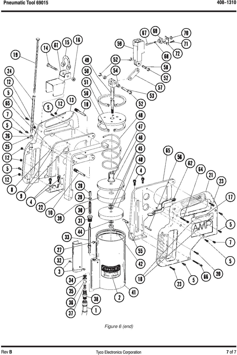
5 The air system of the tool must receive lubrication via an air line lubricator. Refer to Paragraph 1.2. Frequency of lubrication should be as follows: Tools used in daily production Lubricate daily Tools used daily (occasional) Lubricate weekly Tools used weekly Lubricate monthly Customer replaceable parts are listed in Figure 6. A complete inventory can be stocked and controlled to prevent lost time when replacement of parts is necessary. Order replacement parts through your Tyco Electronics Representative, or call , or send a facsimile of your purchase order to , or write to: CUSTOMER SERVICE (38 35) TYCO ELECTRONICS CORPORATION P.O. BOX 3608 HARRISBURG, PA Tools may also be returned to Tyco Electronics for evaluation and repair. For tool repair service, contact a Tyco Electronics Representative at Figure 5 Updated document to corporate requirements Deleted obsolete document in Section 1, INTRODUCTION
 TYCO")
6 Figure 6 (cont d)

7 Figure 6 (end)
Reasons for reissue are provided in Section 6, REVISION SUMMARY.
 Reasons for reissue are provided in Section 6, REVISION SUMMARY. The FRONT OF TOOL has the AMP marking on the link. The BACK OF TOOL (Wire Side), into which the wire is inserted, has the wire size marked
758 Heavy-duty Ratchet Guy Wire Cutter
 INSTRUCTION MANUAL 758 Heavy-duty Ratchet Guy Wire Cutter Read and understand all of the instructions and safety information in this manual before operating or servicing this tool. Register this product
HAND CRIMP TOOL Specification Sheet Order No. 63819-0900
 HAND CRIMP TOOL Specification Sheet Order No. 63819-0900 FEATURES TYPE 4D ΠA full cycle ratcheting hand tool ensures complete crimps ΠErgonomic soft grip handles for comfortable crimping ΠA precision
Application Tooling Specification Sheet
 Modular Crimp Head Order No. 63825-2170 Application Tooling Specification Sheet TYPE 4A Hand Crimp Tool Order No. 63825-2100 FEATURES % A full cycle ratcheting hand tool ensures complete crimps % Ergonomically
DUBOX TM LOOSE PIECE HAND TOOL
 DUBOX TM LOOSE PIECE HAND TOOL Hand Tool Part Number HT-2234 22-30 AWG For termination Of Dubox TM 76357-x01LF Terminals FCI MANUAL P/N 10123594-9090 Issued: Date (12/20/2012) Page 1 of 9 HT-2234 HAND
SBC90. Abrasive Blast Cabinet Assembly & Operating Instructions
 SBC90 Abrasive Blast Cabinet Assembly & Operating Instructions READ ALL INSTRUCTIONS AND WARNINGS BEFORE USING THIS PRODUCT. SAVE THESE INSTRUCTIONS FOR FUTURE REFERENCE. This manual provides important
Machine needle shut-off nozzle type HP
 Machine needle shut-off nozzle type HP pneumatically or hydraulically controlled Index of contents Chapter Page Safety instructions... 2 Installation instructions... 3 - Installation steps... 3 Initial
Reasons for reissue are in Section 6, REVISION SUMMARY.
 Figure 1 This instruction sheet covers the application of OPTIMATE FSMA Fiber Optic Connector Types 905 and 906 for data and telecommunications applications. Base part numbers which apply to each type
HT-0095 Mini PV Receptacles 22-32 AWG Crimping Hand Tool. Tool P/N HT-0095
 HT-0095 Mini PV Receptacles 22-32 AWG Crimping Hand Tool Tool P/N HT-0095 FCI MANUAL P/N 415988-001 Issued: Date (03/12/99) Page 1 of 18 HT-0095 Issued: Date (03/12/99) Page 2 of 18 Introduction Table
RAUFOSS EXPLOSIVE COMPRESSION FITTINGS
 INSTRUCTION MANUAL FOR RAUFOSS EXPLOSIVE COMPRESSION FITTINGS Box 7 2831 Raufoss Norway Tlf.: +47 61 15 17 87 Fax: +47 61 15 25 56 25 January 2013, rev 2 Available on www.vpmetall.no Page 1 CONTENTS GENERAL
Figure 1 (end) Updated document to corporate requirements Added text to Paragraph 2.4
 Updated document to corporate requirements Added text to Paragraph 2.4") This specification covers the requirements for application of ELCON Drawer Series Connectors: True Hot Plug, Blind Mating Mixed Signal and Power Connectors. These connectors are designed for use in pluggable
This specification covers the requirements for application of ELCON Drawer Series Connectors: True Hot Plug, Blind Mating Mixed Signal and Power Connectors. These connectors are designed for use in pluggable
Hydraulic Air Riveter. Operation Manual RC197 RC198. Recommend for mass production line industrial area. Page 1
 Hydraulic Air Riveter Recommend for mass production line industrial area Operation Manual RC197 RC198 Page 1 CONTENTS 1 Important Safety Rules 2 Tool Specification 2.1 Nomenclature 2.2 Technical Data 3
HYDRAULIC LIFT TABLE CART 2200-LB.
 HYDRAULIC LIFT TABLE CART 2200-LB. OWNER S MANUAL WARNING: Read carefully and understand all MACHINE ADJUSTMENT AND OPERATION INSTRUCTIONS before operating. Failure to follow the safety rules and other
SERVICE GUIDE For WARN PULLZALL 120v AC &100v AC P/N 685000 & 685001
 SERVICE GUIDE For WARN PULLZALL 120v AC &100v AC P/N 685000 & 685001 REPAIR / REPLACEMENT INSTRUCTIONS TROUBLE SHOOTING GUIDE 986765A2.doc Page 1 of 50 WARNING This guide identifies potential hazards and
Tech. Services: (800) 477-8326 Fax: (800) 765-8326 Order Entry: (800) 541-1418 Fax: (800) 288-7031 Internet Address: http://www.powerteam.
 477-8326 Fax: (800) 765-8326 Order Entry: (800) 541-1418 Fax: (800) 288-7031 Internet Address: http://www.powerteam.") ORIGINAL INSTRUCTIONS Form No.102842 5 SPX Hydraulic Technologies 5885 11th Street Rockford, IL 61109-3699 USA Tech. Services: (800) 477-8326 Fax: (800) 765-8326 Order Entry: (800) 541-1418 Fax: (800)
ORIGINAL INSTRUCTIONS Form No.102842 5 SPX Hydraulic Technologies 5885 11th Street Rockford, IL 61109-3699 USA Tech. Services: (800) 477-8326 Fax: (800) 765-8326 Order Entry: (800) 541-1418 Fax: (800)
1000-LB. TRAILER JACK OWNER S MANUAL
 1000-LB. TRAILER JACK OWNER S MANUAL WARNING: Read carefully and understand all INSTRUCTIONS before operating. Failure to follow the safety rules and other basic safety precautions may result in serious
MCR1900 Media Converter 19-Slot Chassis
 MCR1900 Media Converter 19-Slot Chassis Installation Guide Part #5500304-11 Copyright Statement This document must not be reproduced in any way whatsoever, either printed or electronically, without the
Failure to comply with the following cautions and warnings could cause equipment damage and personal injury.
 1.0 IMPORTANT RECEIVING INSTRUCTIONS Visually inspect all components for shipping damage. Shipping Damage is not covered by warranty. If shipping damage is found, notify carrier at once. The carrier is
SECTION G2: CABLE PROCESSOR MODULE MAINTENANCE
 SECTION G2: CABLE PROCESSOR MODULE MAINTENANCE Cable Processor Module overview WARNING! When tipping the Cable Processor Module back, (after removing the toggle arm pin), use extreme caution not to drop
BoWex SD, SD1 and SD2 Operating-/Assembly Instructions
 D-807 Rheine 0111 E 1 curved-tooth gear couplings are flexible shaft connections. They are able to compensate for shaft displacement caused by, as an example, inaccuracies in production, heat expansion,
Assembly Instruction CAI- Connector with universal Endbell
 CANNON STANDARD Seite 1 von 17 CAI- Connector with universal Endbell Shell size 10 to 36 with APK contact / Trident T2P - contact Illustration and assembly exemplary of CAI Layout 20-0306 with APK / Trident
IMPORTANT DOCUMENTATION DO NOT DISCARD!
 PART NO.: 6441-263C SERIES GRT 3 JAW PARALLEL GRIPPERS INFORMATION SHEET IMPORTANT DOCUMENTATION DO NOT DISCARD! Use this information sheet to assist with gripper installation and setup. File with maintenance
Unit: mm(in) Item Standard value Service limit Axle shaft run out - 0.2(0.008)
 Item Standard value Service limit Axle shaft run out - 0.2(0.008)") Rear Wheel/Brake/Suspension 13. Rear Wheel/Brake/Suspension Service Information 13-1 Troubleshooting 13-2 Rear Wheel 13-3 Rear Cushion 13-4 Rear Swing Arm 13-7 Service Information General Safety If the
Rear Wheel/Brake/Suspension 13. Rear Wheel/Brake/Suspension Service Information 13-1 Troubleshooting 13-2 Rear Wheel 13-3 Rear Cushion 13-4 Rear Swing Arm 13-7 Service Information General Safety If the
ROTEX SD shiftable jaw coupling
 4014 E 1 SD shiftable jaw coupling Schutzvermerk Gezeichnet: 14.08.06 Sha Ersatz für: vom 9.07.85 4014 E SD is a torsionally flexible jaw coupling shiftable at standstill. It is able to compensate for
HYDRAULIC TABLE CART 500-LB.
 HYDRAULIC TABLE CART 500-LB. OWNER S MANUAL WARNING: Read carefully and understand all MACHINE ADJUSTMENT AND OPERATION INSTRUCTIONS before operating. Failure to follow the safety rules and other basic
Cable Hoist. Operating, Maintenance & Parts Manual. Follow all instructions and warnings for LMCA680. Americrane & Hoist Corp.
 Americrane & Hoist Corp. -800-5-93 Cable Hoist LMCA80 Operating, Maintenance & Parts Manual Cable Hoist Follow all instructions and warnings for inspecting, maintaining and operating this hoist. The use
MODEL G300 BRAKE BLEEDER
 MODEL G300 BRAKE BLEEDER Installation, Operation & Repair Parts Information Branick Industries, Inc. 4245 Main Avenue P.O. Box 1937 Fargo, North Dakota 58103 REV060616 P/N: 81-0035G 1 THIS PAGE INTENTIONALLY
EnduraLAM 150 User Manual
 EnduraLAM 150 User Manual SIGNWarehouse, Inc. 2614 Texoma Drive Denison, Texas 75020 800-699-5512 Website: www.signwarehouse.com Email: [email protected] Copyright 2014 SIGNWarehouse, Inc.
7.1 Safety Precautions-Aircraft and Workshop 3 3 3. 7.2 Workshop Practices 3 3 3
 Note: This module does not apply to category B3. Relevant subject matters for category B3 are defined in module 7B. 7.1 Safety Precautions-Aircraft and Workshop 3 3 3 Aspects of safe working practices
Directory chapter 02 - DIN Power (to 6 A) Types D, E, F, FM, 2F, F9, interface connectors I/U 02. 01. Technical characteristics types D and E... 02.
 Types D, E, F, FM, 2F, F9, interface connectors I/U 02. 01. Technical characteristics types D and E... 02.") Directory chapter 02 - () Types D, E, F, FM, 2F, F9, interface connectors I/U Page Technical characteristics types D and E.............................. 02.10 Type D connectors.................... 02.11
Directory chapter 02 - () Types D, E, F, FM, 2F, F9, interface connectors I/U Page Technical characteristics types D and E.............................. 02.10 Type D connectors.................... 02.11
15GAL STEEL OIL DRAIN WITH 110V PUMP
 15GAL STEEL OIL DRAIN WITH 110V PUMP OWNER S MANUAL WARNING: Read carefully and understand all ASSEMBLY AND OPERATION INSTRUCTIONS before operating. Failure to follow the safety rules and other basic safety
TERMINATION EQUIPMENT INSTRUCTION MANUAL TELE-PIERCE P/N 356-246
 TERMINATION EQUIPMENT INSTRUCTION MANUAL TELE-PIERCE P/N 356-246 OPERATION AND SERVICE INSTRUCTIONS AMPHENOL 157 SERIES TELE-PIERCE MULTI-WIRE TERMINATION TOOL 356-246 AMPHENOL TERMINATION SYSTEMS 1830
tire inflator with pressure gauge
 tire inflator with pressure gauge Model 95583 Assembly And Operation Instructions Due to continuing improvements, actual product may differ slightly from the product described herein. 3491 Mission Oaks
INSPECTION, MAINTENANCE AND RECHARGE SERVICE MANUAL P/N 16303
 WATER MIST HAND PORTABLE FIRE EXTINGUISHERS Model B270 ¾ Gallon Model B272 2 ½ Gallon INSPECTION, MAINTENANCE AND RECHARGE SERVICE MANUAL P/N 6303 All fire extinguishers should be installed, inspected
TECHNICAL BULLETIN. Meritor WABCO Cab Leveling Valves and Chassis Leveling Valves. How the Cab Leveling and Chassis Leveling Valves Work
 Revised 02-00 TECHNICAL BULLETIN Meritor WABCO Cab Leveling Valves and Chassis Leveling Valves This technical bulletin covers both cab and chassis leveling valves manufactured by Meritor WABCO. While the
7 Watt Solar Charger Solar Panel
 7 Watt Solar Charger Solar Panel Owner s Manual Warning: Read carefully and understand all ASSEMBLY AND OPERATION INSTRUCTIONS before operating. Failure to follow the safety rules and other basic safety
4RU High Density Shelf Installation Instructions
 4RU High Density Shelf Installation Instructions Table of Contents General Product Information... 1.0 Safety Precautions... 2.0 Tools Required... 3.0 Package Contents... 4.0 Installing the Product Unpacking...
Safety, Operation and Maintenance Manual with Parts List
 Safety, Operation and Maintenance Manual with Parts List 20-Gallon Wet/Dry Vac Important Information and Safety Instructions PLEASE READ BEFORE USE! # 961130020 9/10-Rev 1 20-Gallon Wet/Dray Vac TABLE
8 ton air/hydraulic long ram jack
 8 ton air/hydraulic long ram jack Model 94562 Set up and Operating Instructions Visit our website at: http://www.harborfreight.com Read this material before using this product. Failure to do so can result
FJ2. 2 Ton Trolley Floor Jack Assembly & Operating Instructions
 FJ2 2 Ton Trolley Floor Jack Assembly & Operating Instructions READ ALL INSTRUCTIONS AND WARNINGS BEFORE USING THIS PRODUCT. This manual provides important information on proper operation & maintenance.
INSTALLATION & OPERATING INSTRUCTIONS
 INSTALLATION & OPERATING INSTRUCTIONS WARNING RISK OF ELECTRIC SHOCK. CONNECT ONLY TO A CIRCUIT PROTECTED BY A GROUND-FAULT CIRCUIT-INTERRUPTER. THE UNIT SHOULD BE INSTALLED BY A QUALIFIED SERVICE REPRESENTATIVE.
RIVET BUSTERS. 9949 Tabor Place, Santa Fe Springs, California, CA 90670, U.S.A.
 S Website: www.apt-tools.com e-mail: [email protected] TDS-1038 Rev A S TOOL MAINTENANCE & REPAIR INFORMATION FIELD OPERATION: Before use: 1. Fill and attach an in-line oiler to the air tool. Use air
Back Pack Sprayer. Operator's Manual MODELS MS - 40 MS - 50
 Back Pack Sprayer Operator's Manual MODELS MS - 40 MS - 50 WARNING DANGER Read rules for safe operation and all instructions carefully. ECHO provides this Operator's Manual which must be read and understood
FX TYPHOON 12. Table of Contents
 Owner s Manual FX TYPHOON 12 Table of Contents Table of Contents Warranty Specifications General Instructions Operating Instructions Loading the Magazine Trigger Adjustments Care & Maintenance Recommended
ADDENDUM USER MANUAL LBV300S-6, LBV300XL & LBV600XL
 ADDENDUM USER MANUAL LBV300S-6, LBV300XL & LBV600XL DOCS-004 Rev C The information, photographs, illustrations and descriptions contained in this manual are the property of SeaBotix Inc. Unauthorized duplication
OPERATING INSTRUCTION MANUAL FOR S-240 HYDRAULIC CUTTERS WITH PARTS LIST
 HUSKIE TOOLS, INC. OPERATING INSTRUCTION MANUAL FOR S-240 HYDRAULIC CUTTERS WITH PARTS LIST GENERAL INFORMATION GUIDE FOR S-240 CUTTER The following steps are guidelines for safe operation of the Huskie
DIAMOND Retractable Rodding Robot Model SPRAYROD-R
 2004-12-21 2 1 (23) DIAMOND Retractable Rodding Robot Model SPRAYROD-R 2004-12-21 2 2 (23) Table of contents 1 TECHNICAL DESCRIPTION...4 1.1 MAIN DETAILS...5 1.2 COMPONENTS DESCRIPTION...5 1.2.1 Pneumatic
R O A D M A S T E R, I N C.
 R O A D M A S T E R, I N C. ROADMASTER, Inc. 6110 NE 127th Ave. Vancouver, WA 98682 4 MOUNTING BRACKET KIT 1 2 3 360-896-0407 fax 360-735-9300 www.roadmasterinc.com ITEM QTY NAME PART # 1...2... #10 x
System Saver 318 Air Compressor for Mack E-Tech and ASET Engines
 Maintenance Manual 31 System Saver 318 Air Compressor for Mack E-Tech and ASET Engines Revised 08-05 NON-THROUGH DRIVE THROUGH DRIVE Service Notes About This Manual This manual provides service and repair
Char-Lynn Hydraulic Motors. Repair Information. W Series Geroler Motors 002, 003. April, 1999
 Char-Lynn Hydraulic Motors April, 1999 Repair Information W Series Geroler Motors 002, 003 W Series Geroler Motors Tools Required 5/16 inch Hex Key Bullet for Shaft Installation - Eaton Tool No. 600633
Rear wheel brakes, servicing. Стр. 1 из 45. Note:
 Volkswagen Touareg - Rear wheel brakes, servicing Стр. 1 из 45 46-2 Rear wheel brakes, servicing Rear brakes, FN 44 brake caliper, servicing Note: After replacing brake pads, depress brake pedal firmly
Rail Vehicle Systems IP-241. Rev 07 3/9/2016 - en. Installation and Maintenance Guide. Slack Adjuster Model KRD-482-E and KRD-482-R P/N 783901, 790196
 Rail Vehicle Systems IP-241 Rev 07 3/9/2016 - en Installation and Maintenance Guide Slack Adjuster Model KRD-482-E and KRD-482-R P/N 783901, 790196 Contact Address New York Air Brake 748 Starbuck Avenue
DTM04 TANK MONITOR DTM08 TANK MONITOR Dtm12 TANK MONITOR. Installation and Operation Manual
 DTM04 TANK MONITOR DTM08 TANK MONITOR Dtm12 TANK MONITOR Installation and Operation Manual 1 ENGLISH Safety Instructions 2 Features 2-3 Specifications 3 Installation 4-5 Wiring Diagrams 6-7 Warranty 8
- power windows - alarm system - electric door mirror control - door warning light - central locking - seat memory
 Door Wiring Harness Plug Connections Binder -, Electrics Vehicle Type: (86) Model Year: 7 (V) Concern: Door wiring harness plug connections X11 / X12. Information: The rubber boot for the door connector
Pet hair clipper. Model 96822. Diagrams within this manual may not be drawn proportionally.
 Pet hair clipper Model 96822 Cleaning And Operation Instructions Diagrams within this manual may not be drawn proportionally. Due to continuing improvements, actual product may differ slightly from the
TECHNICAL GUIDE. For Self-Shielded Guns - 300, 400 and 500 amp SAFETY AND WARRANTY INFORMATION INSTALLATION MAINTENANCE GUIDE TECHNICAL DATA OPTIONS
 TECHNICAL GUIDE For Self-Shielded Guns - 300, 400 and 500 amp SAFETY AND WARRANTY INFORMATION INSTALLATION MAINTENANCE GUIDE TECHNICAL DATA OPTIONS EXPLODED VIEW & PARTS LIST TROUBLESHOOTING ORDERING INFORMATION
STORED PRESSURE STAINLESS STEEL
 STORED PRESSURE STAINLESS STEEL WATER FIRE EXTINGUISHERS Model 240-2-1/2 Gallon OWNER'S SERVICE MANUAL NO. 05601 INSPECTION, MAINTENANCE AND RECHARGE All fire extinguishers should be installed, inspected
Model 2128 AIR COMPRESSOR PUMP Operating Instructions
 Model 8 AIR COMPRESSOR PUMP Operating Instructions Assembly of pump Connection to cylinder and charging ) Connect the air hose to the air cylinder and tighten with spanner. Do not over tighten. Note; the
TBM5, TBM5-S and TBM5-SV
 TBM5, TBM5-S and TBM5-SV Compression Tool Instructions Read and understand all of the instructions and safety information in this manual before operating or servicing this tool. Table of Contents 1.0 Operating
Installation Instructions Avalanche XUV Cap IMPORTANT! IMPORTANT!
 Installation Instructions Avalanche XUV Cap IMPORTANT! Read all instructions carefully before commencing any work. Always wear safety equipment. Some installation steps will require two or more installers.
- Do not immerse cords, pump or any electrical wire or device in water or other liquid.
 TRANSFER PUMP INSTRUCTIONS FOR THE SUPER TRANSFER PUMP 1. Pump (water may be present in the pump and lines due to testing at factory) 2. Instructions. 3. Inlet thicker wall hose (1), outlet hose (1) 4.
3620 W 11th Streetб Houston, TX 77008 Telephone: 713-635-6291 Email: [email protected] Website: www.kellogg-american.com
 Unpackaging & Handling Be sure to carefully inspect the unit before accepting the shipment. If any damage has occurred document it with the trucking company immediately. Contact your Kellogg Distributor
BACKPACK SPRAYERS. MODEL NOS: KSP16 & KSP20 Part Nos: 3402270 & 3402275 OPERATING & MAINTENANCE INSTRUCTIONS GC04/12
 BACKPACK SPRAYERS MODEL NOS: KSP16 & KSP20 Part Nos: 3402270 & 3402275 OPERATING & MAINTENANCE INSTRUCTIONS GC04/12 INTRODUCTION Thank you for purchasing this CLARKE Sprayer, designed for use only with
TRS 090/105 Compressor. Repair Procedures
 TRS 090/105 Compressor Repair Procedures GENERAL FGG All repair and service operations should be performed on a clean bench and with the use of clean tools. Use genuine parts and correct tools for all
STEERING HANDLEBAR/FRONT WHEEL/ FRONT SHOCK ABSORBER
 14 14 STEERING HANDLEBAR/FRONT WHEEL/ SCHEMATIC DRAWING ------------------------------------------------- 14-1 SERVICE INFORMATION------------------------------------------------ 14-2 TROUBLESHOOTING-----------------------------------------------------
Table of Contents. www.hunterfan.com. What to Expect with. Preparation. Tools Needed. Wiring. Hanging the Fan. Blades. Motor Housing.
 www.hunterfan.com Table of Contents What to Expect with Your Installation 30 inches Hanging the Fan Wiring 8 Maintenance, Operation & Cleaning Light Kit 13??? 14 1 9 Troubleshooting 11 5 Blades Motor Housing
ARCO Electric Products Installation and Maintenance Manual Low Voltage Automatic Power Factor Correction Capacitor Systems 2013
 ARCO Electric Products Installation and Maintenance Manual Low Voltage Automatic Power Factor Correction Capacitor Systems 2013 READ CAREFULLY These instructions are intended to cover good practices in
2 HP / 4 GALLON AIR COMPRESSOR OWNER'S MANUAL
 2 HP / 4 GALLON AIR COMPRESSOR OWNER'S MANUAL WARNING: Read carefully and understand all INSTRUCTIONS before operating. Failure to follow the safety rules and other basic safety precautions may result
USER INSTRUCTIONS FOR 10 LITRE PORTABLE DEHUMIDIFIER MODEL NO. DHMD102
 USER INSTRUCTIONS FOR 10 LITRE PORTABLE DEHUMIDIFIER MODEL NO. DHMD102 THANK YOU FOR CHOOSING YOUR NEW DEHUMIDIFIER. BEFORE USING THE UNIT READ THESE INSTRUCTIONS FULLY AND RETAIN THEM FOR FUTURE REFERENCE
CamSplice Assembly Manual
 Corning Cable Systems SRP-006-038 Issue 9, September 2000 Page 1 of 6 CamSplice Assembly Manual Table of Contents 1. General... 1 2. Precautions... 1 3. Tools and Materials... 2 4. Cable and Fiber Preparation...
Assembly and Usage Instructions
 Assembly and Usage Instructions A Product 5885 West Van Horn Tavern Road Columbia, MO 65203 www.caldwellshooting.com Instruction #1001667 Limited Warranty Every Caldwell product is warrantied to be free
BILLET HEADLAMP WITH SHORT/TALL MOUNTS
 -J099 REV. 00-0- BILLET HEADLAMP WITH SHORT/TALL MOUNTS GENERAL Kit Number 9-0, 9-0 Models Kit 9-0 is a -/ inch headlamp and kit 9-0 is a -/ inch headlamp. Both kits will fit the models listed in Table.
Navico-Northstar 2kW JRC Radar Package, Scanner Cable Removal and Replacement
 Navico-Northstar 2kW JRC Radar Package, Scanner Cable Removal and Replacement This work instruction describes the methods and means for which to remove and reinstall optional scanner cable configurations
Front brakes (FN- 3), servicing
, servicing") j a t Front brakes (FN- 3), servicing 46-1 Front brakes, servicing Note: Install complete repair kit. After replacing brake pads and before moving vehicle, depress brake pedal several times firmly to properly
j a t Front brakes (FN- 3), servicing 46-1 Front brakes, servicing Note: Install complete repair kit. After replacing brake pads and before moving vehicle, depress brake pedal several times firmly to properly
CHIPPING HAMMERS. 9949 Tabor Place, Santa Fe Springs, California, CA 90670, U.S.A.
 CHIPG HAMMERS Website: www.apt-tools.com e-mail: [email protected] TDS-1056 Rev A CHIPG HAMMERS TOOL MAINTENANCE & REPAIR INFORMATION FIELD OPERATION: Before use: 1. On 650 Series tools, tighten the handle
Trouble Shooting. Pump
 Trouble Shooting Pump Trouble Possible Cause Remedy Oil leaking in the area of water pump crankshaft Worn crankshaft seal, bad bearing, grooved shaft, or failure of retainer o-ring. Excessive play on crankshaft
BLAST CABINET ABRASIVE. 59001 Rev 59001-20090526 SAVE THESE INSTRUCTIONS. Important Safety Instructions are included in this manual
 59001 Rev 59001-20090526 10006 Santa Fe Springs Road Santa Fe Springs, CA 90670 USA Made in China Owner s Manual and Operating Instructions SAVE THESE INSTRUCTIONS Important Safety Instructions are included
MODELS 93/693 By CO2 SEMI-AUTOMATIC
 O p e r a t i o n M a n u a l MODELS 93/693 By CO2 SEMI-AUTOMATIC.177 cal BB (4.5 mm) STEEL AIRGUN SHOT 12gm CO2 cylinder only WARNING: NOT A TOY. ADULT SUPERVISION REQUIRED. MISUSE OR CARELESS USE MAY
FOXAIR 60/50 ALL MODELS
 FOXAIR 60/50 ALL MODELS OPERATION AND SERVICE MANUAL UNIT WEIGHT - ALL MODELS APPROX. 300 POUNDS FOXTRONICS, INC. 38 L x 28 W x 24 H Love Field-Dallas TX MADE IN THE USA 3448 West Mockingbird Lane Dallas,
5800 Temperature Sensor Cable Assembly
 5800 Temperature Sensor Cable Assembly Removal and Replacement Instruction Sheet #60-4702-070 Revision D, January 14, 2013 Overview The 5800 has two refrigeration temperature sensors, one attached to the
Failure to comply with the following cautions and warnings could cause equipment damage and personal injury.
 1.0 IMPORTANT RECEIVING INSTRUCTIONS Visually inspect all components for shipping damage. Shipping Damage is not covered by warranty. If shipping damage is found, notify carrier at once. The carrier is
13. REAR WHEEL/BRAKE/SUSPENSION
 13. REAR WHEEL/BRAKE/SUSPENSION 13 3.5~4.5kg-m 8.0~10.0kg-m 0.8~1.2kg-m 3.0~4.0kg-m 2.4~3.0kg-m 3.5~4.5kg-m 6.0~8.0kg-m 13-0 13. REAR WHEEL/BRAKE/SUSPENSION 13 REAR WHEEL/BRAKE/SUSPENSION SERVICE INFORMATION...
TAMPERS. 9949 Tabor Place, Santa Fe Springs, California, CA 90670, U.S.A.
 TAMPERS Website: www.apt-tools.com e-mail: [email protected] TDS-1064 Rev A S TOOL MAINTENANCE & REPAIR INFORMATION FIELD OPERATION: Before use: 1. Check the tamping butt lock screw, it must be tightened
FABA 100 Insulated Conductor System. Mounting Instructions. Fon: +49 (2307) 704 0 Fax: +49 (2307) 704 444 E-Mail: [email protected]
 704 0 Fax: +49 (2307) 704 444 E-Mail: info@vahle.de") Insulated Conductor System s Seite 1 Page 3 System Contents Page Introduction 4 Hanger Clamp (Stud-mounting with spring clip) 6 Hanger Clamp (Clip-type) 7 Conductor Rails 8 Conductor Rails Shortening 8
Insulated Conductor System s Seite 1 Page 3 System Contents Page Introduction 4 Hanger Clamp (Stud-mounting with spring clip) 6 Hanger Clamp (Clip-type) 7 Conductor Rails 8 Conductor Rails Shortening 8
MP-4V Heavy Duty Riveter / 39048
 MP-4V Heavy Duty Riveter / 39048 This newly designed heavy-duty air/hydraulic riveter is ergonomically designed with the professional in mind. The light weight 3.7 lbs. well balanced MP-4V includes a Vacuum
A&A CORVETTE PERFORMANCE C6 BOOST & FUEL GAUGE INSTALLATION INSTRUCTIONS
 A&A CORVETTE PERFORMANCE C6 BOOST & FUEL GAUGE INSTALLATION INSTRUCTIONS 1. Check your gauges before you take them out of the packaging to make sure they are at 0 (zero) psi for both boost and fuel pressure.
Fiberstars Lighted Laminar Flow Fountain Installation Manual
 Fiberstars Lighted Laminar Flow Fountain Installation Manual 79-15037-00 REV Xx http://www.fiberstars.com Page 1 of 8 SAVE THESE DIRECTIONS! These directions are provided to ensure the proper installation
Notes. Material 1. Tools the employee is expected to operate
 OSHA Standard29 CFR 1910.211-.247, Subpart O, Machinery and Machine Guarding, and Subpart P, Hand and Portable-Powered Tools and other Hand- Held Equipment. Hand Tool Safety Preparation 1. Read Applicable
Instruction Manual. Alfa Laval SB Membrane Sample Valve ESE02963-EN1 2015-10. www.sks-online.com www.sks-webshop.com.
 Instruction Manual Alfa Laval SB Membrane Sample Valve ESE02963-EN1 2015-10 Original manual Table of contents The information herein is correct at the time of issue but may be subject to change without
INSTALLATION INSTRUCTIONS MULTI-MOUNT KIT Part Number: 75330 Application: Warn HP PowerPlant P/N 71800
 INSTALLATION INSTRUCTIONS MULTI-MOUNT KIT Part Number: 75330 Application: Warn HP PowerPlant P/N 71800 Your safety, and the safety of others, is very important. To help you make informed decisions about
HAND PUMP OPERATION, SERVICE AND PARTS INSTRUCTION MANUAL
 OPERATION, SERVICE AND PARTS INSTRUCTION MANUAL 767 HAND PUMP Read and understand this material before operating or servicing this equipment. Failure to understand how to safely operate this tool could
PNEUMATIC PLANISHING HAMMER
 PNEUMATIC PLANISHING HAMMER 94847 ASSEMBLY AND OPERATING INSTRUCTIONS Due to continuing improvements, actual product may differ slightly from the product described herein. Distributed Exclusively by Harbor
Figure 2 The fan and shroud also needs to be removed for access to the four a/c compressor bolts and removal of the compressor from the top.
 Here are some pictures to show what s required when replacing the A/C compressor, expansion valve and receiver/drier on a 2001 Volvo V70. Even if you don t replace these A/C parts these pictures can help
MODEL T200-F18 MODEL T125-F18 Finish Nailers
 P MODEL T200-F18 MODEL T125-F18 Finish Nailers IMPORTANT! DO NOT DESTROY It is the customer s responsibility to have all operators and service personnel read and understand this manual. OPERATING MANUAL
OPERATOR S MANUAL 18 VOLT, 1 HOUR CHARGER
 OPERATOR S MANUAL 18 VOLT, 1 HOUR CHARGER P110 Your battery charger has been engineered and manufactured to Ryobi s high standard for dependability, ease of operation, and operator safety. When properly
NUMBER: 08 DD15-10 S.M. REF.: 3.2 ENGINE: DD15 DATE: September 2008
 NUMBER: 08 DD15-10 S.M. REF.: 3.2 ENGINE: DD15 DATE: September 2008 SUBJECT: 3.2 OIL PAN PUBLICATION: DDC-SVC-MAN-0002 Oil pan section 3.2 has been updated. Section Change 3.2 Oil Pan Call-outs have been
AMPSEAL* Automotive Plug Connector and Header Assembly
 AMPSEAL* Automotive Plug Connector and Header Assembly Application Specification 24 SEP 97 Rev E All dimensions are given in millimeters unless otherwise specified. All dimensional tolerances are +0.2
GENUINE PARTS INSTALLATION INSTRUCTIONS
 GENUINE PARTS INSTALLATION INSTRUCTIONS DESCRIPTION: Illuminated Kick Plate APPLICATION: Rogue (2011) PART NUMBER: 999G6 GX010 KIT CONTENTS: Item A B C G H QTY 1 1 1 D 1 E 1 F 3 15 6 Description Kick Plate,
2008 ACCORD - Front Knuckle/Hub/Wheel Bearing Replacement (page 18-13)
") 2008 ACCORD - Front Knuckle/Hub/Wheel Bearing Replacement (page 18-13) Exploded View Special Tools Required Ball joint remover, 28 mm 07MAC-SL0A202 Hub dis/assembly tool 07GAF-SD40100 Bearing driver attachment,
2008 ACCORD - Front Knuckle/Hub/Wheel Bearing Replacement (page 18-13) Exploded View Special Tools Required Ball joint remover, 28 mm 07MAC-SL0A202 Hub dis/assembly tool 07GAF-SD40100 Bearing driver attachment,
Extrusion Flo-Valve INSTRUCTIONS-PARTS LIST. 3000 psi (210 bar) Maximum Working Pressure. Model 204 355, Series K. Rev.
 Maximum Working Pressure. Model 204 355, Series K. Rev.") INSTRUCTIONS-PARTS LIST INSTRUCTIONS This manual contains important warnings and information. READ AND KEEP FOR REFERENCE. 306 586 Rev. D Supercedes B Extrusion Flo-Valve Model 204 355, Series K 3000 psi
INSTRUCTIONS-PARTS LIST INSTRUCTIONS This manual contains important warnings and information. READ AND KEEP FOR REFERENCE. 306 586 Rev. D Supercedes B Extrusion Flo-Valve Model 204 355, Series K 3000 psi