Installation Instructions. Thermo Call TC3
|
|
|
- Gavin Lamb
- 9 years ago
- Views:
Transcription
1 Installation Instructions Thermo Call TC3

2 1 2 # 24990A AMP 3 4 # 98393A # 67769A

3 sw
4 Improper installation or repair of Webasto heating and cooling systems can cause fire or the leakage of deadly carbon monoxide leading to serious injury or death. To install and repair Webasto heating and cooling systems you need to have completed a Webasto training course and have the appropriate technical documentation, special tools and special equipment. Only genuine Webasto parts may be used. See also Webasto air and water heaters accessories catalogue. NEVER try to install or repair Webasto heating or cooling systems if you have not completed a Webasto training course, you do not have the necessary technical skills and you do not have the technical documentation, tools and equipment available to ensure that you can complete the installation and repair work properly. ALWAYS carefully follow Webasto installation and repair instructions and heed all WARNINGS. Webasto rejects any liability for problems and damage caused by the system being installed by untrained personnel.

5 D Content Installation Instructions...6 General information...6 Certification...6 Delivery scope...6 GSM module wiring harness...7 Legend...7 SIM card...7 Installation...8 Installing GSM module...8 Installing GSM antenna...8 Installing push button...8 Connection...9 Connector assignment of GSM module...9 Connection of an alarm system installed in the vehicle (option)...10 Connection of an external temperature sensor (option)...10 Connection to heater...11 Thermo Top Evo or Thermo Top E/C...11 Thermo Top Evo or Thermo Top E/C with digital timer...11 Thermo Top Evo or Thermo Top E/C with Telestart T91/T100 HTM...11 Connection of summer/winter wire (only with Thermo Top E/C)...11 Final connection and commissioning...12 Technical data...13 Drawing of installation location for GSM module in vehicle...14
...11 Final connection and commissioning...12 Technical data.")
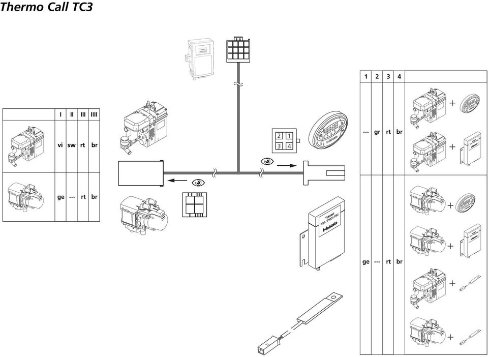
6 Installation Instructions General information With the Thermo Call TC3, retrofitted Webasto heaters of the Thermo Top E/C series and the Thermo Top Evo series can be operated with a mobile or fixed network phone. Details are contained in the operating instructions. The function cannot be guaranteed in conjunction with OE heaters. Please turn over these installation instructions to the customer together with the operating instructions. Certification The CE marking and the e-marking are located on the adhesive label on the module. Delivery scope 1 Thermo Call TC3 GSM module 2 Summer/winter cable 3 GSM module wiring harness 4 GSM antenna 5 Push button incl. LED 6 Self-tapping screws and (not shown): - Additional cable for Output 2 - Installation Instructions - Operating Instructions

7 GSM module wiring harness The included GSM module wiring harness must be adjusted with corresponding "pinning into" the existing installation situation (heater selection). For this purpose, the tied-back wires are stripped at the two connection plugs in the direction of the heater and heater control, then the required wires are inserted according to the illustrations on the cover pages and the wire ends not required are tied back again insulated.. Legend On the illustrations on the cover pages. br ge gr rt sw vi brown yellow grey red black purple --- not in use SIM card Thermo Top E Thermo Top C Thermo Top Evo A SIM card not included in the delivery scope is required to operate the unit. Both 1.8 V and 3 V SIM cards of a network operator, which supports the GSM 900/1800 mobile communications standard, can be used. Always observe any information of the respective network operator when operating the SIM card. Before inserting the SIM card, the PIN code must be changed to 1234 with a mobile phone. Information on this topic is contained in the respective operating instructions of the mobile phone. All data which may be present on the SIM card will be deleted when commissioning the GSM module. The SIM card is inserted under the sliding cover on the top of the GSM module with the angled side opposite the hinge and with the chip side facing downward. Only insert or remove the SIM card in the deenergised state. The range is dependent on the respective network operator. Costs result from the operation of a SIM card. Information on this topic and on roaming charges abroad and in areas close to the border (due to network overlapping) can be obtained from the respective network operator. 7

8 Installation Installing GSM module The GSM module must be installed in the passenger compartment. - Specify the installation location in the passenger compartment (preferably under the instrument panel, when retrofitting preferably near the digital timer or the radio receiver). - Fasten the GSM module with self-tapping screws (ensure sufficient clearance for the connection of the wiring harness and the antenna) - Watch vehicle parts located behind the module when mounting it with the selftapping screws! NOTE Please mark the installation location of the GSM module on the last page of these installation instructions for any replacement of the SIM card! Installing GSM antenna The antenna must be installed on the front or rear window. However, never in the tinted area or under the heating wires of the window heater or wires of the window antenna. - Clean the window thoroughly with a cleaning cloth - Pull the protective film off the antenna and glue on the antenna (maintain a minimum distance of 30 mm from metal parts) - Route the antenna cable to the GSM module (never shorten or kink) and connect to the module Installing push button The push button contained in the delivery scope must be installed. - To do this, drill an 8 mm dia. hole in a blind switch or another suitable location easily accessible to the driver (coordinate the installation location with the vehicle owner if necessary) - Mount the push button in the 8 mm dia. hole - Route the push button wiring harness to the 12-pin connector on the module and connect it to the module (blue wire on Pin 9, green on Pin 10 and red on Pin 11) 8 mm dia. 8

9 Connection Connector assignment of GSM module Socket Function Remarks V (+30) 2 Earth = 0 3 Output of parking heater only for Thermo Top E/C 4 additional analogue output, V positive * for 2nd installed heater with analogue control 5 Earth output for summer function (fan only) only for Thermo Top E/C 6 W bus communication with parking heater or digital timer/telestart only for Thermo Top Evo 7 not in use (optional Input 1 for alarm system) +12 V 8 Input 2 (for digital timer/telestart) only for Thermo Top E/C 9 Earth for push button (blue wire) 10 On/Off for push button (green wire) 11 Output for LED in push button (red wire) 12 not in use *: The connection may vary depending on the installed 2nd heater. Information on the integration is contained in the respective heater installation instructions. 9
 11 Output for LED in push button (red wire) 12 not in use *: The connection may vary depending on the installed 2nd heater.")
10 Connection of an alarm system installed in the vehicle (option) It is possible to connect an alarm system in the vehicle. The vehicle owner receives a text message when the alarm system is triggered. Insert the wire in Pin 7 of 12-pin connector and connect it to the output of the alarm system (must be a +12 V signal). To define which text message content the TC3 is to use to inform you, send the following text message command to the TC3 following commissioning: 1234IBANK:"Entry command". The entry command can, for example, be Alarm. The alarm can be sent to up to 5 phone numbers. To define which phone numbers are to be used, send the following text message command to the TC3: 1234NBANK:XXX:YYY:ZZZ:VVV:WWW XXX:YYY:ZZZ:VVV:WWW = phone numbers to be entered by the user, e.g.: : :etc. Connection of an external temperature sensor (option) This is required for measuring the temperature outside the Thermo Call TC3 (e.g. for cargo areas) and for using the temperature alarm function. Required material: - W bus temperature sensor A (not required in combination with Telestart T100 HTM) - Y-adapter A (only required if a digital timer 1533 is connected after the Thermo Call TC3) - See the Webasto Accessories Catalogue for any required extensions Carry out the connection in as shown in the following drawing and illustrations on the inner cover pages. To use the temperature alarm, the phone numbers to be notified must be reported to the Thermo Call TC3. To define the phone numbers, the following text message command must be sent to the Thermo Call TC3: 1234NBANK:XXX:YYY:ZZZ:VVV:WWW XXX:YYY:ZZZ:VVV:WWW = phone numbers to be entered by the user, e.g.: : :etc. For details, see operating instructions. 10

11 Connection to heater Thermo Top Evo or Thermo Top E/C Insert GSM module wiring harness: see Section "GSM module wiring harness" on Page 7 and illustrations on the inner cover pages. - Connect the 4-pin connector of the heater wiring harness to the 4-pin GSM module wiring harness Not used Thermo Top Evo or Thermo Top E/C with digital timer Insert GSM module wiring harness: see Section "GSM module wiring harness" on Page 7 and illustrations on the inner cover pages. - Connect the 4-pin connector of the heater wiring harness to the 4-pin GSM module wiring harness - Connect the 4-pin GSM module connector to the digital timer to the digital timer Thermo Top Evo or Thermo Top E/C with Telestart T91/T100 HTM Insert GSM module wiring harness: see Section "GSM module wiring harness" on Page 7 and illustrations on the inner cover pages. - Connect the 4-pin connector of the heater wiring harness to the 4-pin GSM module wiring harness - Connect 4-pin GSM module connector to the Y-adapter of the Telestart To the special Y-Adapter Connector of heater wiring harness Connector of heater wiring harness Connector of heater wiring harness Connection of summer/winter wire (only with Thermo Top E/C) - Connect the purple wire contained in the delivery scope to the purple wire of the heater wiring harness using a connector 11

12 - Insert the micro-timer in a free slot of the 4-pin connector of the heater wiring harness Final connection and commissioning - Connect the 12-pin connector of the GSM module wiring harness to the module - After connecting voltage, the button will flash 2x cyclically - After approx. 1 minute, the button will flash 1x cyclically and, depending on the dial-in time of the SIM card, can take a total of up to 5 minutes until it is finally ready for operation - As soon as operational readiness is achieved, program the Thermo Call TC3 and put it into operation according to the operating instructions - To query the firmware version send the text message command "VERSION" to the Thermo Call TC3 12

13 Technical data Power supply 8 to 35 V DC Bias current consumption A Current consumption during data transfer A Max. output current A Max. input voltage 35 V Switching voltage for inputs +5.5 V Permissible ambient temperature -40 C to +85 C Permissible storage temperature -40 C to +85 C Dimensions (LxWxH) 95x55 (75) x30 mm Weight 100 g Protection type IP50 Material PBT 13

14 Drawing of installation location for GSM module in vehicle Note or sketch the installation location of the GSM module in the following field for possible service cases. 14

15 In multilingual versions the German language is binding. The telephone number of each country can be found in the Webasto service center leaflet or the website of the respective Webasto representative of your country. Webasto Thermo & Comfort SE Postfach Gilching Deutschland Visitors address: Friedrichshafener Str Gilching Germany Internet: Technical Extranet: Ident-Nr B_EN 07/12 Errors and omissions excepted Webasto Thermo & Comfort SE, 2012

Installation Instructions. ThermoCall TC4. Entry/Advanced
 Installation Instructions ThermoCall TC4 Entry/Advanced Thermo Call TC4 1 2 # 24990A 965 082 AMP 3 4 # 98393A # 67769A Thermo Call TC4 5 ThermoCall TC4 Entry 1 2 3 4 5 6 7 8 9 10 11 12 sw Please refer
Operating Instructions Thermo Call TC3. General Information. Use. Dear Webasto customer,
 Operating Instructions Thermo Call TC3 General Information Dear Webasto customer, Thank you for purchasing the new Thermo Call TC3. This product provides you with a convenient, innovative way to operate
How To Use A Power Supply On A Powerline 2.2 (Ai)
") KNX/EIB Product documentation Issue: 05.08.2010 629x1220 Push button sensor 3 comfort 1-gang Push button sensor 3 comfort 2-gang (1+1) Push button sensor 3 comfort 3-gang Push button sensor 3 comfort 4-gang
KNX/EIB Product documentation Issue: 05.08.2010 629x1220 Push button sensor 3 comfort 1-gang Push button sensor 3 comfort 2-gang (1+1) Push button sensor 3 comfort 3-gang Push button sensor 3 comfort 4-gang
Operating Instructions. ThermoCall TC4. Entry / Advanced
 Operating Instructions ThermoCall TC4 Entry / Advanced Table of Contents 1 About This Document......................................... 1 2 General Information..........................................
GSM HOME SECURITY SYSTEM
 Cell /Mobile phone home security system GSM HOME SECURITY SYSTEM Model : GSM-120 TABLE OF CONTENTS 1. FEATURES... 1 2. APPLICATION... 2 3. SPECIFICATIONS... 3 4. FRONT PANEL & LAYOUT DESCRIPTION...6 5.
Parts and Accessories Installation Instructions
 Parts and Accessories Installation Instructions R5 5 Z CD changer retrofit kit MINI (R 5 and R 53) LHD and RHD The installation time is approx..5 hours, but this may vary depending on the condition of
www.sebury.com.cn Digital Keypad Use s Manual
 K3 K4 www.sebury.com.cn Digital Keypad Use s Manual Contents Introduction Introduction Specifications Intramural Interface Circuit 3 Mounting 3 Wiring 5 Power UP 7 Engineer Programming Mode 7 The K3/K4
Falcon Protector Tracking System
 Falcon Protector Tracking System Product Overview The Falcon Protector is a GPS and GSM tracking device which is specially developed and designed for vehicle tracking. With the latest SIFR III GPS module
USER MANUAL V5.0 ST100
 GPS Vehicle Tracker USER MANUAL V5.0 ST100 Updated on 15 September 2009-1 - Contents 1 Product Overview 3 2 For Your Safety 3 3 ST100 Parameters 3 4 Getting Started 4 4.1 Hardware and Accessories 4 4.2
ALWAYS follow all Webasto installation and repair instructions and observe all warnings.
 Water Heater Unit Feel the drive Thermo Top E Additional Heater Thermo Top C Additional Heater Thermo Top P Additional Heater e 00 0003 e 00 000 e 00 004 Installation Instructions Mazda 6 Gasoline from
Product and functional description
 Product and functional description The KNX / DALI gateway N 141/02 is a 4 MU wide, DINrail mounted KNX device with one DALI interface to which up to 64 DALI actuators (e.g. DALI ballasts) can be connected
IPThermo206G. Offline/online data collector, SMS alarm sender, watchdog terminal for IPThermo Pro network
 IPThermo206G Offline/online data collector, SMS alarm sender, watchdog terminal for IPThermo Pro network IPThermo 206G is the central data handling terminal of the IPThermo Pro measurement network. This
BMW Parts and Accessories Installation Instructions
 BMW Parts and Accessories Installation Instructions Retrofit Anti-theft Alarm System (DWA) series-identical retrofit for BMW 5 Series saloon and touring (E 9, E 9/) left-hand drive F 9 005 W Installation
Wireless Home Security Alarm System AM 500
 Wireless Home Security Alarm System AM 500 12 MONTH GUARANTEE Installation & Operating Instructions INTRODUCTION The AM500 is a simple self-contained alarm system. It protects the home by sounding a siren
SVC400P/SVC800P. 4/8 Camera Live Tracking Vehicle DVR Installation Manual. Version 1.0
 SVC400P/SVC800P 4/8 Camera Live Tracking Vehicle DVR Installation Manual Version 1.0 1. MAIN FEATURES... 2 2. PRODUCT OVERVIEW... 2 3. DIMENSIONS... 4 4. PACKAGE CONTENTS... 5 5. MOUNTING AND ENVORNMENTAL
Coolant heater. Thermo Top - Z/C additional heating system. Installation instructions. Volvo S60, Volvo V70, and Volvo S80 Beginning Model Year: 2000
 Coolant heater Thermo Top - Z/C additional heating system Approval code ~~~ S 9 Installation instructions Volvo S60, Volvo V70, and Volvo S80 Beginning Model Year: 000 6 6 7 8 Volvo XC70 Beginning Model
SECURITY SYSTEM ADP-CAN
 INSTALLATION INSTRUCTION SECURITY SYSTEM ADP-CAN Introduction Motorcar security system ADP-CAN is for motorcars provided with CAN net. It is for the work with the motorcar factory security systems or remote
USER MANUAL V5.0 VT300
 GPS Vehicle Tracker USER MANUAL V5.0 VT300 Updated on 26/12/2008 Contents 1 Product Overview 3 2 For Your Safety 3 3 VT300 Parameters 3 4 Getting Started 4 4.1 Hardware and Accessories 4 4.2 Light and
ALWAYS follow all Webasto installation and repair instructions and observe all warnings.
 Water Heater Unit Feel the drive Thermo Top E Additional Heater Thermo Top C Additional Heater Thermo Top P Additional Heater e 00 0003 e 00 000 e 00 004 Installation Instructions Fiat Grande Punto Gasoline
HERZ-Thermal Actuators
 HERZ-Thermal Actuators Data Sheet 7708-7990, Issue 1011 Dimensions in mm 1 7710 00 1 7710 01 1 7711 18 1 7710 80 1 7710 81 1 7711 80 1 7711 81 1 7990 00 1 7980 00 1 7708 11 1 7708 10 1 7708 23 1 7709 01
Multi Function, User Configurable Remote Vehicle Security System with 4 Button Replaceable Membrane Remote Transmitter
 MODEL PRO-9744 INSTALLATION MANUAL Multi Function, User Configurable Remote Vehicle Security System with 4 Button Replaceable Membrane Remote Transmitter This System Allows The Transmitter Buttons To Be
Operating instructions Diffuse reflection sensor. OJ50xx 701396 / 01 07 / 2004
 Operating instructions Diffuse reflection sensor OJ50xx 7096 / 0 07 / 004 Contents Preliminary note. Symbols used Function and features Installation. Installation of the supplied mounting fixture 4 4 Electrical
Inwall 4 Input / 4 Output Module
 Inwall 4 Input / 4 Output Module IO44C02KNX Product Handbook Product: Inwall 4 Input / 4 Output Module Order Code: IO44C02KNX 1/27 INDEX 1. General Introduction... 3 2. Technical data... 3 2.1 Wiring Diagram...
tidesmarine Smart Seal Temperature Alarm System Generation II Installation Instructions Starboard side cable
 tidesmarine Smart Seal Temperature Alarm System Generation II Installation Instructions Starboard side cable Port side cable (with black cable tie attached) Power cable Preparing for Installation 1 Overall
INSTALLATION MANUAL INSIDE PASSENGER COMPARTMENT. HFC 134a FOR EUROPEAN SPEC. / GENERAL SPEC. AIR CONDITIONING ENGLISH
 HFC 134a Ozone Friendly Refrigerant FOR EUROPEAN SPEC. / GENERAL SPEC. AIR CONDITIONING ENGLISH AAAMU-60 / INSIDE PASSENGER COMPARTMENT INSTALLATION MANUAL 2000 (EUROPE) B.V.. All Rights Reserved. This
Original BMW Accessory. Installation Instructions.
 Original BMW Accessory. Installation Instructions. Connector Retrofit for External Audio Sources BMW Series (E 46), BMW 5 Series (E9) from 9/, BMW X5 (E 5) from /, BMW X (E8), BMW Z4 (E85/E86) These installation
Manual for Fire Suppression & Methane Detection System
 Manual for Fire Suppression & Methane Detection System Fogmaker North America Post address: 150 Gordon Dr Exton, PA 19341 Delivery address: 150 Gordon Dr Exton, PA 19341 Tel: 610-265-3610 Fax: 610-265-8327
Roadstar Installation Instruction Manual
 Roadstar Installation Instruction Manual This instruction manual describes installation of GPS/GPRS vehicle tracking device Roadstar. Modem is already set to work with system for vehicle tracking, and
Before installation it is important to know what parts you have and what the capabilities of these parts are.
 INSTALLATION GUIDE Before installation it is important to know what parts you have and what the capabilities of these parts are. The Recon XZT is the smallest and most powerful gauge of its kind. With
KEYLESS ENTRY UPGRADE SECURITY SYSTEM for 2004 TOYOTA HIGHLANDER
 KEYLESS ENTRY UPGRADE SECURITY SYSTEM for 2004 TOYOTA HIGHLANDER DEALER SERVICE AND INSTALLATION MANUAL KIT NO. 00016-30915 Contents PARTS LIST... 2 PARTS ILLUSTRATIONS... 2 VEHICLE PREPARATION... 3 INSTALLING
TX GSM SMS Auto-dial Alarm System. Installation and User Manual
 TX GSM SMS Auto-dial Alarm System Installation and User Manual Product Features: 1. 16 wireless zones, 3 wired zones alarm system, suitable for small to medium size offices and homes. 2. The system uses
INSTALLATION INSTRUCTIONS
 INSTALLATION INSTRUCTIONS Accessory Application Publications No. ACCORD All 30209 2-AND 4-DOOR SYSTEM (VP, LX, SE) Issue Date AUG 2005 PARTS LIST Security System Attachment: P/N 08E55-SDA-100A Unit panel
GSM Remote control. Version W-BUS v9.x. Operating manual
 GSM Remote control Version W-BUS v9.x Operating manual Antenna Status LED Release SMA Connection SIM card Front view Release PIN 1 PIN 8 Back view Table of contents 1 Scope of delivery...4 2 Safety instructions...5
INSTALLATION INSTRUCTIONS
 INSTALLATION INSTRUCTIONS Accessory Application Publications No. AII23628 2003 PILOT Issue Date MAY 2002 PARTS LIST Security System Kit (sold separately): P/N 08E51-S84-100 2 Remote controls Attachment
GENUINE PARTS INSTALLATION INSTRUCTIONS
 GENUINE PARTS INSTALLATION INSTRUCTIONS DESCRIPTION: Illuminated Kick Plate APPLICATION: Rogue (2011) PART NUMBER: 999G6 GX010 KIT CONTENTS: Item A B C G H QTY 1 1 1 D 1 E 1 F 3 15 6 Description Kick Plate,
2003/2004/2005 TOYOTA COROLLA
 2003/2004/2005 TOYOTA COROLLA KEYLESS ENTRY UPGRADE SECURITY SYSTEM INSTALLATION INSTRUCTIONS KIT NO. 00016-30120 SPECIAL NOTE: Installation Sequences After TMS and Safety mandated preparatory steps have
KVT-729DVD INSTALLATION MANUAL
 MONITOR WITH DVD RECEIVER KVT-729DVD INSTALLATION MANUAL B54-4516-00/00 (EV) Accessories 1 0...1...1 2!...1...2 3...1 4 5...1...1 6...2 7...4 8...4 9...2 2 KVT-729DVD Installation Procedure 1. To prevent
A&A CORVETTE PERFORMANCE C6 BOOST & FUEL GAUGE INSTALLATION INSTRUCTIONS
 A&A CORVETTE PERFORMANCE C6 BOOST & FUEL GAUGE INSTALLATION INSTRUCTIONS 1. Check your gauges before you take them out of the packaging to make sure they are at 0 (zero) psi for both boost and fuel pressure.
USER INSTRUCTIONS FOR GET PORTABLE 12k BTU AIR CONDITIONER MODEL No. GPACU12HR
 USER INSTRUCTIONS FOR GET PORTABLE 12k BTU AIR CONDITIONER MODEL No. GPACU12HR CONTENTS Introduction Safety Notes Identification of parts Installation instructions Operation instructions Maintenance Troubleshooting
Original BMW Accessory. Installation Instructions.
 Original BMW Accessory. Installation Instructions. USB/Audio Interface SA 6FL Retrofit BMW Series (E 8, E 8, E 87, E 88) BMW 3 Series (E 90, E 9, E 9, E 93) These installation instructions are only valid
Parts and Accessories. Installation Instructions.
 Parts and Accessories. Installation Instructions. Rear-view camera retrofit MINI ONE (R 50) MINI COOPER (R 50) MINI COOPER S (R 53) These installation instructions are only valid for cars with SA 609 (navigation
Installation Instructions
 Installation Instructions For Use with PXPV230, PXPV265, PXPD230, and PXPD265 models Attention! - Please read these instructions completely before attempting installation. Always unplug the power supply
SIT Sports. Safety Tracking System Manual WRC 2015
 SIT Sports Safety Tracking System WRC 2015 V2 1 SIT Sports Tracking Unit The SIT Sports Tracking unit must be fitted and connected in all competitors cars before arrival at scrutineering, where it will
Auxiliary HVAC RAM ProMaster. Standard Tie-in Extreme Climate System
 Auxiliary HVAC RAM ProMaster Standard Tie-in Extreme Climate System Auxiliary HVAC High performance aftermarket heating and cooling systems engineered for vehicle specific platforms that minimize install
Advantium 2 Plus Alarm
 ADI 9510-B Advantium 2 Plus Alarm INSTALLATION AND OPERATING INSTRUCTIONS Carefully Read These Instructions Before Operating Carefully Read These Controls Corporation of America 1501 Harpers Road Virginia
Danfoss Link Mobile Phone Butler
 MAKIG MODER LIVIG POSSIBLE Installation Guide www.heating.danfoss.com Table of Contents 1 Introduction... 3 2 Installation... 3 3 Interfaces... 4 4 Wiring... 4 5 SMS Commands... 5 6 Technical Specifications...
Parts and Accessories. Installation Instructions.
 Parts and Accessories. Installation Instructions. High on-board computer retrofit BMW 5 Series (E39) BMW X5 (E53) Retrofit kit No. 65 90 0 308 455 Installation time The installation time is approx,0 -,5
ELECTRONIC THERMOSTAT AND THERMOMETER With SPEED CONTROL
 148 OLD CONCORD TURNPIKE, BARRINGTON NH 03825 USA TEL (603) 868-5720 FAX (603) 868-1040 1-800-435-6708 E-Mail:[email protected] www.seafrost.com ELECTRONIC THERMOSTAT AND THERMOMETER With SPEED CONTROL
Quick start guide smart.power smart.power smart.power
 Quick start guide Intended use: smart.power is a universal charging device for charging (in absence of other charging options) your mobile phone, your TEASI-navigation system or other devices with a 5V
INSTALLATION MANUAL 3RP / 5RP 4-BUTTON SERIES VEHICLE SECURITY SYSTEMS
 3RP / 5RP 4-BUTTON SERIES VEHICLE SECURITY SYSTEMS INSTALLATION MANUAL Before you begin the installation Read the INSTRUCTIONS! Always use a multi-meter when verifying vehicle wiring. Before mounting the
INSTALLATION INSTRUCTIONS
 INSTALLATION INSTRUCTIONS Accessory Application Publications No. All 24393 ACCORD (DX, LX) SYSTEM 2-AND 4-DOOR Issue Date AUG 2002 PARTS LIST Security System Attachment (LX): P/N 08E55-SDA-100A Unit panel
Table of Contents. I. Working Directions...2. II. System Introduction...3. III. Wiring Installation...4. 1. Product Parts List...
 TTS 300 GPS Vehicle Tracker Hardware Installation Manual Table of Contents I. Working Directions...2 II. System Introduction...3 III. Wiring Installation...4 1. Product Parts List... 4 2. Precaution before
OPTICAL HEADEND PLATFORM OTOHP-NMS NETWORK MONITORING MODULE INSTRUCTION MANUAL
 OPTICAL HEADEND PLATFORM OTOHP-NMS NETWORK MONITORING MODULE INSTRUCTION MANUAL Phone: (209) 586-1022 (800) 545-1022 Fax: (209) 586-1026 OTOHP-NMS Rev. X1 E-Mail: [email protected] www.olsontech.com
GSM remote controller v7.0 / v7.0 PRO. Operating Instructions
 GSM remote controller v7.0 / v7.0 PRO Operating Instructions Table of contents 1 Delivery content...3 1.1 optional accessories...3 2 Safety...4 3 Intended use...4 4 responsibility and liability...5 5 Malfunctions...5
Roof Top Air Conditioner INSTALLATION AND OPERATING INSTRUCTIONS
 Roof Top Air Conditioner INSTALLATION AND OPERATING INSTRUCTIONS Ducted System RECORD THIS UNIT INFORMATION FOR FUTURE REFERENCE: Model Number: Serial Number: Date Purchased: This manual must be read and
Alarm over IP. IRIS Touch Home Installation Manual. Version 1.0 ENGLISH. Now certified and compliant with EN50131, EN50136 Security Grade 4 ATS6
 Alarm over IP IRIS Touch Home Installation Manual Version 1.0 ENGLISH Now certified and compliant with EN50131, EN50136 Security Grade 4 ATS6 1. Introduction No more bulky batteries, just one sleek unit
Antenna Splitter ASA 1. Instruction manual
 Antenna Splitter ASA 1 Instruction manual Contents Important safety instructions... 2 The ASA 1 active antenna splitter... 4 Delivery includes... 4 Operating elements... 5 Putting the ASA 1 into operation...
I STAR COMPUTER CO., LTD
 I STAR COMPUTER CO., LTD Mini Redundant Power Supply 300W+300W for IPC-Computer Model No. TC-300R8 Table of content 1. Introduction...1 2. Specification 2.1 Input Voltage...1 2.2 DC Output...1 2.3 PS-ON
Business/ Home GSM Alarm System
 Business/ Home GSM Alarm System BUSINESS/HOME GSM ALARM SYSTEM POWER STATUS RECORD SIGNAL User Manual Profile For a better understanding of this product, please read this user manual thoroughly before
WARNING! REQUIRED TOOLS & SUPPLIES: HIGH VOLTAGE
 INSTRUCTIONS Product: GEM Electric Motorcars Models: All Subject: Instructions for installing Stereo Accessory Estimated Completion Time:.75 Hours Parts: See Page # 7 REQUIRED TOOLS & SUPPLIES: (1) 3/8
B.IQ push button 3-5gang with room thermostat and display V2, flush-mounted 7566359x, 7566459x, 7566559x
 B.IQ push button 3-5gang with room Product name: Design: ETS search path: B.IQ push button 3-, 4-, 5gang with room thermostat and display V2 Flush-mounted Push button / B.IQ / B.IQ push button xgang with
ALWAYS follow all Webasto installation and repair instructions and observe all warnings.
 Water Heater Unit Feel the drive Thermo Top E Additional Heater Thermo Top C Additional Heater Thermo Top P Additional Heater e 00 0003 e 00 000 e 00 004 Installation Instructions Kia cee'd Gasoline and
GTR-128/GTR-129 Motorcycle/ Vehicle Tracker Quick Start Guide
 GTR-128/GTR-129 Motorcycle/ Vehicle Tracker Quick Start Guide GlobalSat WorldCom Corporation 16F., No. 186, Jian 1 st Rd, Zhonghe Dist., New Taipei City 23553, Taiwan Tel: 886.2.8226.3799/ Fax: 886.2.8226.3899
HCS-3300/3302/3304 USB Remote Programmable Laboratory Grade Switching Mode Power Supply
 1. INTRODUCTION HCS-3300/3302/3304 USB Remote Programmable Laboratory Grade Switching Mode Power Supply User Manual This family of efficient, upgraded SMPS with small form factor, auto cross over CV CC,
INSTALLATION INSTRUCTIONS
 Rear Vision System Tailgate Handle Camera Mirror Display 2004-2014 Ford F-150 and 2008-2015 Ford Super Duty (Kit part numbers 9002-9521) Kit Contents: Mirror Tailgate Handle with camera and harness Interior
Disabled Toilet Alarm. Contractor Pack. Installation & Operating Instructions
 Disabled Toilet Alarm Installation & Operating Contractor Pack Installation & Operating Instructions 1 Overview The Channel Safety Systems Disabled Toilet alarm contractor Packs are an efficient way of
NewAir AC-10100E / AC-10100H Portable Air Conditioner Owner s Manual PLEASE READ AND SAVE THESE INSTRUCTIONS
 NewAir AC-10100E / AC-10100H Portable Air Conditioner Owner s Manual PLEASE READ AND SAVE THESE INSTRUCTIONS ELECTRICAL SAFETY This appliance is for indoor use only. Always turn off the unit and unplug
PUSH BUTTON START INSTALLATION MANUAL
 PUSH BUTTON START INSTALLATION MANUAL ALTHOUGH THIS PRODUCT HAS BEEN THOROUGHLY TESTED KPIERSON TECHNOLOGIES ASSUMES NO RESPONSIBILITY FOR ANY DAMAGE THAT MAY RESULT BY THE INSTALLATION OF THIS PRODUCT.
ILISC515-A Shift Interlock (Manual Lift Door) 2015 Ford Transit, 3.7L and 3.5L
 2015 Ford Transit, 3.7L and 3.5L") An ISO 9001:2008 Registered Company ILISC515-A Shift Interlock (Manual Lift Door) 2015 Ford Transit, 3.7L and 3.5L Introduction The ILISC515-A is a microprocessor driven system for controlling wheelchair
An ISO 9001:2008 Registered Company ILISC515-A Shift Interlock (Manual Lift Door) 2015 Ford Transit, 3.7L and 3.5L Introduction The ILISC515-A is a microprocessor driven system for controlling wheelchair
How To Program An Autodialer
 GJD HYL005 GSM Autodialer Instruction Manual Please read these instructions before you start the installation Features: LCD display. Programmable 9 x 32 digit phone numbers for each trigger. 10 second
LED...A70..4-..Q Series Sealed High-Intensity
 LED...A70..4-..Q Series Sealed High-Intensity Area Lights High-Power Lighting for use with PresencePLUS and Other Vision Systems Features Rugged, waterproof housing, rated IEC IP68 Compact area light for
PRODUCT: WASHER / WASHER-DRYER COMBO MODEL: AW 120 / AW 122 / AW 125 AWD 120 / AWD 121 / AWD 129
 PRODUCT: WASHER / WASHER-DRYER COMBO MODEL: The information included in this Splendide Repair Manual may change without notice. Please see our web site www.splendide.com/service/docs.html for updates,
Instrument panel. Volkswagen Touareg - Instrument panel. Special tools, testers and auxiliary items required. Release lever T10039
 Volkswagen Touareg - Instrument panel Page 1 / 14 70-1 Instrument panel Tools Special tools, testers and auxiliary items required Release lever T10039 Instrument panel, removing and installing Removing
Detector transparent with Color Inserts. FAA 500 TR P Trim Ring transparent with Color Inserts. FCA 500 / FCA 500 E Detector Bases
 Detector Color Detector transparent with Color Inserts FAA 500 TR W Trim Ring FAA 500 TR P Trim Ring transparent with Color Inserts FAA 500 BB Ceiling Mount Back Box FCA 500 / FCA 500 E Detector Bases
Transporter Fitting Locations No. 804 / 1
 Page 1 of 10 Transporter Fitting Locations No. 804 / 1 Pin connector assigment of selected connections Overview: 1 - Ignition/starter switch -D- On steering column Connector assigment chapter 2 - Onboard
Color Mark Sensor with Red or Green LED E3S-VS
 Color Mark Sensor with Red or Green LED Rugged IP67 Color Mark Sensor 1 ms response time Detects a wide variety of color marks PNP or NPN output ls Light-on/ Dark-on operation, wire selectable Vertical
I Click on a link tab to jump to that page. Cover Page
 & nstall Publication, Duplication, or Retransmission Of This Document Not Expressly Authorized n Writing By The nstall Doctor s Prohibited. Protected By U.S. Copyright Laws. 1997,1998,1999,2000. Factory
INSTALLATION INSTRUCTIONS
 INSTALLATION INSTRUCTIONS Accessory Application Publications No. AII 26327 2004 S2000 Issue Date OCT 2004 PARTS LIST Security System: P/N 08E51-S84-100 Attachment Kit: P/N 08E55-S2A-101 2 Remote controls
GENUINE PARTS INSTALLATION INSTRUCTIONS
 GENUINE PARTS INSTALLATION INSTRUCTIONS 1. DESCRIPTION: Auto-Dimming Mirror Kit with Compass and HomeLink 2. APPLICATION: Titan 3. PART NUMBER: 999L1 WS000 4. KIT CONTENTS: Item Qty Description Service
Inwall Room Temperature Unit
 Inwall Room Temperature Unit TM11B01KNX TM11B11KNX TM11B21KNX Product Handbook Product: Inwall Room Temperature Unit Order Code: TM11B01KNX TM11B11KNX TM11B21KNX Application Program ETS: TM11B_1KNX Inwall
MCR1900 Media Converter 19-Slot Chassis
 MCR1900 Media Converter 19-Slot Chassis Installation Guide Part #5500304-11 Copyright Statement This document must not be reproduced in any way whatsoever, either printed or electronically, without the
- power windows - alarm system - electric door mirror control - door warning light - central locking - seat memory
 Door Wiring Harness Plug Connections Binder -, Electrics Vehicle Type: (86) Model Year: 7 (V) Concern: Door wiring harness plug connections X11 / X12. Information: The rubber boot for the door connector
1R / 4-BUTTON SERIES
 Button 1 1R / 4-BUTTON SERIES VEHICLE SECURITY SYSTEM Standard Features: Two 4-Button Remote Transmitters Status indicator (LED) Valet / override switch Multi-tone siren Dual stage impact detector Remote
XG2. Flat Cable Connectors for PCBs. Achieve Total Cost Reduction through High-density Mounting and Reduced Wiring. Terminal Arrangement
 Flat Cable Connectors for PCBs XG2 Achieve Total Cost Reduction through High-density Mounting and Reduced Wiring IDC connections allow you to wire all terminals at once without terminating the cable. Can
INFRARED QUARTZ WALL HEATER
 INFRARED QUARTZ WALL HEATER MODEL NO: IQ2000 PART NO: 6939004 MOUNTING & OPERATION INSTRUCTIONS GC0715 INTRODUCTION Thank you for purchasing this CLARKE Infrared Wall Heater. Before attempting to use this
Installation Instructions
 H5HK Series Installation Instructions 3 Phase Electric Heater Kits 7.5 and 0 TON Package A/C Systems Description Installation of 08/40V and 480V H5HK 3 Phase Heater Kits in 7.5 and 0 TON Packaged Air Conditioners.
Bathroom Cabinet. Installation & User Guide. Illuminated Mirrors. www.illuminated-mirrors.uk.com
 Illuminated Mirrors The UK s Largest LED Mirror Supplier to Trade and Retail Installation & User Guide Bathroom Cabinet www.illuminated-mirrors.uk.com Bathroom Cabinet Installation & User Guide Thank you
CONTENTS. 1. CE DECLARATION OF CONFORMITY FOR MACHINES pag.11. 2. DESCRIPTION pag.12. 3. TECHNICAL SPECIFICATIONS pag.13. 4. INSTALLATION pag.
 CONTENTS 1. CE DECLARATION OF CONFORMITY FOR MACHINES pag.11. DESCRIPTION pag.1 3. TECHNICAL SPECIFICATIONS pag.13 4. INSTALLATION pag.13 5. TESTING THE AUTOMATED SYSTEM pag.19 6. MANUAL OPERATION pag.19
STATUS POWER MONITOR ALARM SOS DISARM
 STATUS POWER MONITOR ALARM SOS DISARM I. Features II. Preparation before use III. Host 1.LED status explanation 2. Host panel IV. System Settings 1. Coding of wireless sensors 2. Exit coding 3. Settings
Heat Surge Model X5C Fire Place Insert Service Manual Applies to all units w/30000208 circuit board
 Heat Surge Model X5C Fire Place Insert Service Manual Applies to all units w/30000208 circuit board 2012 HS M4417A BR16597R-1 HEAT SURGE 8000 FREEDOM AVE, N. CANTON, OH 44720 330-244-8161 WWW.HEATSURGE.COM
GSM AD05 Slave GSM Auto Dialer- Instruction Manual
 GSM AD05 Slave GSM Auto Dialer- Instruction Manual Please read these instructions before you start the installation Features LCD display Programmable 9 x 32 digit phone numbers for each trigger. 10 second
Portable Air Conditioner
 Portable Air Conditioner Owner's Manual Model:3 in 1 12,000 Btu/h Series 3 Please read this owner s manual carefully before operation and retain it for future reference. CONTENTS 1. SUMMARY...1 2. PORTABLE
Getting started with
 PART NO. CMA113 MADE IN CHINA 1. Measuring CAT II 2. Max. voltage 250V ~ 3. Max. current 71 Amp Getting started with Electricity consumption monitoring single phase for homes and some smaller light commercial
Original BMW Accessories. Installation Instructions.
 Original BMW Accessories. Installation Instructions. Rear view camera retrofit BMW X5 (E70) These installation instructions are only valid for cars with: SA 508 (PDC) with SA 601 (TV function) SA 508 (PDC)
COLOR VIDEO DOOR PHONE CDV-71BE/D
 COLOR VIDEO DOOR PHONE CDV-71BE/D 513-11, Sangdaewon-dong, Jungwon-gu, Seongnam-si, Gyeonggi-do, Korea Int l Business Dept. : Tel.; +82-31-7393-540~550 Fax.; +82-31-745-2133 Web site : www.commax.com Printed
Stove Guard Kit User Manual
 Stove Guard Kit User Manual Innohome improves the Safety of your Home. inno home www.innohome.com Stove Guard Kit User Manual Stove Guard Kit User Manual Congratulations! You now own one of the most intelligent
Radio Thermostat Clock Part Number: 30800009. Installation & User Instructions. Suitable for all Ferroli Combination Boilers
 Radio Thermostat Clock Part Number: 30800009 Installation & User Instructions Suitable for all Ferroli Combination Boilers 2 Short Description Short description Radio Thermostat Clock - Transmitter The
PCS300 Universal IP Reporting Module V1.0
 PCS300 Universal IP Reporting Module V1.0 Reference and Installation Manual Patents: One or more of the following US patents may apply: 7046142, 6215399, 6111256, 6104319, 5920259, 5886632, 5721542, 5287111,
User Manual. ATX12V / EPS12V Power Supply TG-I460R (460W+460W) TG-I550R (550W+550W) Switching Power Supply User Manual
 TG-I550R (550W+550W) Switching Power Supply User Manual") ATX12V / EPS12V Power Supply TG-I460R (460W+460W) TG-I550R (550W+550W) User Manual Table of Contents 1 Introduction 2 General specification 3 Installation 4 Pin assignment & function of connectors 5 Drawing
ATX12V / EPS12V Power Supply TG-I460R (460W+460W) TG-I550R (550W+550W) User Manual Table of Contents 1 Introduction 2 General specification 3 Installation 4 Pin assignment & function of connectors 5 Drawing