Heat Surge Model X5C Fire Place Insert Service Manual Applies to all units w/ circuit board
|
|
|
- Stephanie Maxwell
- 8 years ago
- Views:
Transcription
1 Heat Surge Model X5C Fire Place Insert Service Manual Applies to all units w/ circuit board 2012 HS M4417A BR16597R-1 HEAT SURGE 8000 FREEDOM AVE, N. CANTON, OH

2 Preface This manual is intended for the servicing of the Heat Surge Model X5C fireplace insert. Only authorized trained technicians should use this manual and perform the service needed. Risk of electrical shock, burn and fire is present when performing service to the insert. The following tools are needed: Multi-meter Voltage sensor Flat head screwdriver Phillips head screwdriver Needle nose pliers Side cutters Flashlight Well lighted work area with 120vac switchable source Specifications Model X5C Electric Fireplace Insert 120v/60Hz, 15A, 1500W Quantity 2 clear candelabra bulbs with E-12 (small) sockets, 120vac, 40W, 60HZ Quantity 1 flame tube motor, 120vac, 40ma, 3.7W, 60HZ Quantity 1 blower motor, 120vac, 60HZ Quantity 2 heater elements, 120vac, 750W Dimensions 24"W x 21"H x 10"D 2
 sockets, 120vac, 40W, 60HZ Quantity 1 flame tube motor, 120vac,")
3 Table of Contents Description Page Removal of front grill and top cover 4 Incoming Power 5 Lamps 6 Flame Tube 8 Blower Assembly 10 Dual Element Heater with Fusible Link 13 Touch Pad Control 17 Temperature Pot and Temperature Sensor 18 Remote Control and Remote Control Sensor 19 Log removal and replacement 20 Electrical Drawing 21 3

4 Removal of Front Grill and Top Cover To remove the front grill, remove 120vac power from insert, locate the 4 mounting screws, 2 on each side. Remove screws and pull front grill out towards the front. Refer to Figure 1. Front grill assembly 4 mounting screws, 2 on each side Figure 1, removal of front grill To remove the top cover, locate the 9 mounting screws, 2 on each side and 5 in the back of the insert. Remove the screws and pull forward while at the same time lifting out. Be careful to not damage the 2 cables running to the main control board. Remove both cables from their respective sockets and remove top. When laying the top down to service the insert, insolate the touchpad and temperature pot being careful not to short out to the insert case ground. Refer to Figure 2. 2 cables, touch pad and pot 5 mounting screws located in rear 4 mounting screws, 2 on each side Figure 2, removal of top cover 4

5 Incoming Power The incoming power to the insert is 120vac/60Hz and will draw 15amps when running both heater elements at a total of 1500watts. The incoming power, L1, is protected by a circuit breaker located on the back of the insert. Also the insert is protected by a normally closed tip switch in series with the circuit breaker located inside the top left hand side compartment. To reach this switch the top front grill and the top cover must be removed. The hot lead, L1, is landed on terminal AC-L3 on the main control board. Refer to Figure 4. The common, L2, is landed on terminal AC-N4 on the main control board. When the insert is plugged into an 120vac source there should be 120vac between terminals AC-L3 and AC-N4 on the main control board. If not, inspect plug and plug wire for damage. Also check to make sure the 120vac source is not shut off by either a circuit breaker and/or switch controlling the 120vac source. The ground is landed to the case. Refer to Figure 3. Circuit Breaker Main Control Board Tip Switch Figure 3, Main control board location AC-N1 AC-N2 AC-N3 AC-N4 AC-L3 AC-L2 AC-L1 750W 750W FLAME FAN LAMP Figure 4, Main control board terminal locations 5

6 Lamps There are 2 candelabra lamps each with an E-12 (small) socket base rating voltage 120vac, rating power 40watts. These lamps are located inside the bottom of the insert. Unfasten the 2 screws on the 2 sides of the bottom panel, take out the bottom panel. Refer to Figure 5. 2 Fixing Screw Bottom panel Figure 5, bottom panel screw locations Locate the 2 bulbs in the bottom of the unit. Examine the bulbs to determine which bulb requires replacement. Remove the holding spring on the old bulb and replace the bulb with a new one. Reinstall the holding spring after replacement. Refer to Figure 6. Candelabra bulbs, 120vac, 40watts, E-12 small socket. Holding spring located around each bulb. Figure 6, lamp locations 6

7 If bulbs refuse to light, check the 2 conductor plug for connection. To examine the plug the front glass must be removed. Locate the 6 mounting screws, 3 on each side, remove all 6 and lift off front glass. Next remove the 3 top screws holding the flame screen; the plug is located on the right hand side. The plug will have a yellow and a white wire on one side and a black and white wire leading to the sockets. Check for good connection. Refer to Figure 7. Front glass mounting screws, quantity 6. Flame screen mounting screws, quantity 3. Figure 7, lamp plug location If the plug connection is good, check for voltage between terminals LAMP and AC-N1 on the main control board, (60vac to 120vac depending flame brightness set point). Refer to Figure 3 and Figure 4, for board and terminal locations, if there isn t any voltage present, the main control board is defective, replace with a new board. Repair connection, plug in Lamps. 7

8 Flame Tube The flame tube assembly consists of the flame tube, flame tube motor and mounting brackets. If there isn t any rolling frame the following needs performed. To access the flame tube assembly the front glass must be removed and the flame screen pulled forward. Refer to Figure 9. Look for any jams that may cause interference of the rotating tube. Next, inspect for the mounting of the flame tube. Make sure the 2 fasteners are present which hold the flame tube in its place. Also check for bent brackets which may have caused the flame tube to fall out. Refer to Figure 8. Flame tube fasteners quantity 2. Flame tube motor. Flame tube brackets, quantity 2. Figure 8 If there isn t any interference then inspect the flame tube motor. The flame tube is rotated by a 120vac, 60Hz motor drawing 40ma at 3.7watts which is plugged in, located in the same location as the lamp plug. The plug will have a brown and a white wire on one side and a black and black wire leading to the motor. Check for good connection. Refer to Figure 9. Figure 9 8

9 If the plug connection is good, check for 110vac between terminals FLAME and AC-N1 on the main control board, refer to Figure 1 and Figure 2 for board and terminal locations, if there isn t any 110vac present the main control board is defective, replace with a new board. If there is 110vac replace the flame motor. Repair connection and plug in. 9

10 Blower Assembly The front grill and top of the insert must be removed to service the blower assembly. Refer to Figure 1 and Figure 2. Lift the top off but leave the touch pad and temperature pot plugged in, be careful not to short circuit against the insert casing. Rest the top on the casing so that the touch keypad points straight up. Insolate the touch keypad from the casing with cardboard. With 120vac cord plugged in, turn the insert on via the touch keypad. Next select low on the touch keypad, the blower should start running. If it doesn t slightly tap the blower with a screw driver, if unit starts then the problem is a sticky blower. If the blower doesn t start, take a voltage reading from the main control board. There should be 120vac between terminal FAN and AC-N2. Refer to Figure 11. If there isn t 120vac present then the main control board is defective, replace with a new board. Blower Blower Motor 2 stage infrared heating elements Fusible link Heat discharge vent Figure 10, Blower/Heater assembly If the problem is a sticky blower, the blower must be replaced. First with power removed, remove the heat discharge vent from the insert. There are 4 screws, 2 located on each side, remove all 4 and lift straight off. Next remove all wiring associated with the blower motor, heat element and fusible link. The blower motor has 2 black wires which are landed on terminals FAN and AC-N2 of the main control board. Remove these. Refer to Figure 11. AC-N2 FAN Figure 11, blower motor terminals 10

11 Next the dual heating element has 3 wires associated with it, 2 black and 1 white. The 2 black leads are the 120vac power leads landing on terminals both marked 750W on the main control board. The lower heating element terminal lands on the lower 750W terminal on the main control board and the upper heating element terminal lands on the upper 750W terminal on the main control board. The white common wire is landed on terminal AC-N3 on the main control board, remove all 3 wires from main control board. Refer to Figures 12 and 13. Upper 750W heating element terminal Figure 12 Lower 750W heating element terminal AC-N3 AC-L2 AC-L1 750W, (upper terminal) 750W, (lower terminal) Figure 13, dual element heat and fusible link terminal locations. Next remove the 2 blue fusible link leads from terminals AC-L2 and AC-L1 from the main control board. Refer to Figures 13 and 14. Fusible link and blue leads Figure 14, fusible link location 11
 750W, (lower terminal) Figure 13, dual element heat and fusible link")
12 Remove the 4 screws, 2 on each side, holding the blower/heater assembly to the insert. Remove the 4 screws and lift blower/heater assembly off of the insert. Next locate the 4 screws, 2 on each side, attaching the dual element heater to the blower. Remove these screws and remove dual element heater from blower. Refer to Figure 15. Screws holding dual element heater to blower. Figure 15 Replace blower and reverse above procedure to assemble. 12

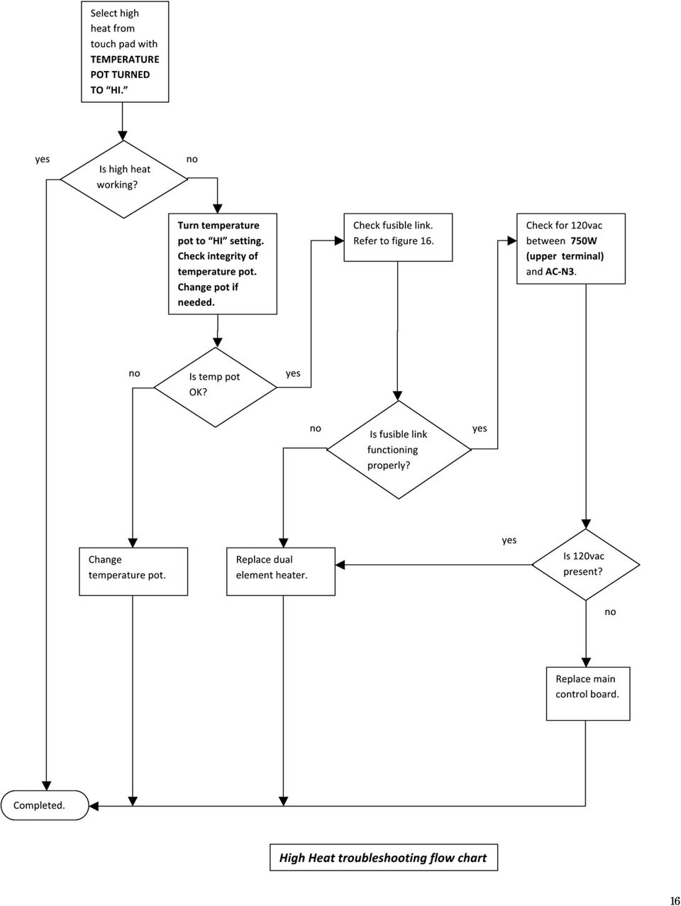
13 Dual Element Heater with Fusible Link The front grill and top of the insert must be removed to service the heater assembly. Refer to Figure 1 and Figure 2. Lift the top off but leave the touch pad and temperature pot plugged in, be careful not to short circuit against the insert casing. Rest the top on the casing so that the touch keypad points straight up. Insolate the touch keypad from the casing with cardboard. With 120vac cord plugged in, temperature pot turned to HI, turn the insert on via the touch keypad. Next select low on the touch keypad, the blower should start running and 10 seconds later the low heat should start; you will hear the contacts clicking of the control relay on the main control board. If low heat does not come on, check for 120vac at the fusible link. Place common test lead on the common terminal of the dual element heater marked A and the hot test lead on the right hand terminal of the fusible link marked B. Refer to Figure 16. Common location A Left hand side of fusible link location C Right hand side of fusible link location B Figure 16, fusible link If 120vac is present, place the hot test lead to the left hand side of the fusible link marked C with the common in the same location. Refer to Figure 16. If 120vac is not present let the unit cool down in order to clear the fusible link. Wait 5 minutes and repeat test. When after repeating the test and there isn t any 120vac present then check for 120vac present between the 750W (lower terminal) and AC-N3 on the main control board. Refer to Figure 17. AC-N3 750W (lower terminal) Figure 17 13

14 If 120vac is not present then replace the main control board. If 120vac is present then the fusible link is defective, replace the dual element/fusible heater. Next select low on the touch keypad, the blower should start running and 10 seconds later the low heat should start; you will hear the contacts clicking of the control relay on the main control board. Select high heat and you will hear the contacts clicking of the control relay on the main control board. If the clicking is not heard, repeat the above test only for high heat. Check for 120vac between terminals 750W (upper terminal) and AC-N3. If 120vac is not present change out main control board. Refer to Figure 18. AC-N3 750W (upper terminal) Figure 18, high heat 120vac In order to change out the dual element heater, remove blower assembly as described in section Blower Assembly. Remove the 4 mounting screws, 2 on each side of the dual element heater. Refer to Figure 19. Remove and replace with new heater assembly. Install blower assembly. Screws holding dual element heater to blower. Figure 19 14
 and AC-N3. If 120vac is not present change out main control board. Refer to Figure 18.")
15 15

16 16
17 Touch Pad Control With the insert sitting up-right, plug the insert into a known good 120vac source. The insert will beep once. Turn the insert on, the lights will light up and there will be a rolling flame. If the insert doesn t beep or the flame and lights turn on instantly or not at all, the touch keypad is defective. Check for ribbon cable leads coming unplugged from both ends. Check to make sure there is a good connection at the main control board socket. Refer to Figures 20 and 21. Thermocouple plug location Temperature low to high pot plug location Remote control sensor plug location Touch keypad plug location Figure 20, plug locations defined on main control board Figure 21, example of ribbon cable coming unplugged from touch pad connector 17

18 Temperature Pot and Temperature Sensor With the insert sitting up-right, plug the insert into a known good 120vac source. The insert will beep once. Turn the insert on, the lights will light up and there will be a rolling flame. Turn on the low heat. The blower will turn on and 10 seconds later the low heat will come on. If it doesn t, make sure the temperature pot is turned to the HI setting. If low heat doesn t come on check to make sure the temperature pot is plugged into the main control board. Refer to Figure 20 for location. Also check to see if there is a good connection at the temperature pot. Refer to Figure 22. Figure 22, example of bad connection at temperature pot Check the integrity of the temperature sensor located just behind the main control board. Refer to Figure 23. Check to make sure the sensor is plugged into the main control board. Refer to Figure 20. If there is a problem, the insert will still heat but without the use of the temperature room setting. If all checks out, refer to section Dual Element Heater and Fusible Link. Figure 23, temperature sensor location 18

19 Remote Control and Remote Control Sensor The unit comes with a remote control complete with power on/off button, low/high heat selector and up/ down flame setting. Refer to Figure 24. Flame up/down Heat low/high Power on/off Figure 24, remote control description If remote control refuses to work check battery orientation and integrity. Refer to Figure 25. Figure 25, battery location and orientation. Also check that the remote control sensor, red plug socket, is plugged in properly into the main control board. Refer to Figure 20. Lastly check the location and integrity of the remote control sensor located behind the flame screen. Refer to Figure 26. Figure 26, remote control sensor 19

20 Log removal and replacement The front glass needs to be removed. Locate the 6 screws, 3 on each side, holding the front glass frame in and remove. Refer to Figure 27. Locate 6 screws, 3 on each side Figure 27 Locate the 4 black rubber plugs, 2 on each side of the insert. Remove rubber plugs and remove the 4 screws holding the log set in the insert. Pull the log set straight out towards the front. Reverse above to install new log set. Refer to Figure 28. Rubber plugs with mounting screws, quantity 4, 2 on each side of insert. Figure 28 20

21 Electrical Drawing 21
Service Manual. 30 Insert. Model Number: EF3003/SF3003/DF3003. UL Part Number 6901110159-0559. (Canadian and Chinese Built) DFB6016 (DFB6016)
 DFB6016 (DFB6016)") Service Manual 30 Insert (DFB6016) Model Number: EF3003/SF3003/DF3003 (Canadian and Chinese Built) DFB6016 UL Part Number 6901110159-0559 IMPORTANT SAFETY INFORMATION: Always read this manual first before
Service Manual 30 Insert (DFB6016) Model Number: EF3003/SF3003/DF3003 (Canadian and Chinese Built) DFB6016 UL Part Number 6901110159-0559 IMPORTANT SAFETY INFORMATION: Always read this manual first before
800-551-1943. HP Laser Jet 2400 Series Fixing Drive Side Plate Assembly Fixing Drive Side Plate Assembly- RM1-1500 page 1
 Fixing Drive Side Plate Assembly- RM1-1500 page 1 CAUTION: Fuser may be hot. Turn off printer, unplug it and allow it to sit for 20 to 30 minutes before performing these maintenance procedures. Fixing
HP Laser Jet 4200/4240/4250/4300/4350 Swing Plate
 HP Laser Jet 4200/4240/4250/4300/4350 Swing Plate 1 Swing Plate Assembly-RM1-0043 1 Swing Plate Kit-5851-2766 (RM1-0043 plus RM1-1091 gear) CAUTION: Fuser may be hot. Turn off printer, unplug it and allow
Service Manual. Model Number VCX1525 VCX1525-WH. UL Part Number 6904000100
 Service Manual Model Number VCX1525 VCX1525-WH UL Part Number 6904000100 IMPORTANT SAFETY INFORMATION: Always read this manual first before attempting to service this fireplace. For your safety, always
IMPORTANT INSTRUCTIONS & OPERATING MANUAL. Houston 50 Inch Electric Wall Mounted Fireplace Black / White
 IMPORTANT INSTRUCTIONS & OPERATING MANUAL Houston 50 Inch Electric Wall Mounted Fireplace Black / White Model Number:MFE5050BK Model Number:MFE5050WH Read these instructions carefully before attempting
Service manual. Website: www.andico.com.au CAUTION - BEFORE SERVICING THE UNIT, READ THE SAFETY - PRECAUTIONS IN THIS MANUAL.
 Website: www.andico.com.au Service manual CAUTION - BEFORE SERVICING THE UNIT, READ THE SAFETY - PRECAUTIONS IN THIS MANUAL. - ONLY FOR AUTHORISED SERVICE PERSONNEL. MODELS: MPK1-09CR-QB8 MPK1-12ER-QB6
Service Guide 12/27/03 TESTING, SERVICE & REPAIR GUIDE (For SH Space Heating Models & RA Water Heating Models)
") TESTING, SERVICE & REPAIR GUIDE (For SH Space Heating Models & RA Water Heating Models) WARNING - HIGH VOLTAGE AC electrical circuits are connected to this heater. Do not attempt any service work on the
TESTING, SERVICE & REPAIR GUIDE (For SH Space Heating Models & RA Water Heating Models) WARNING - HIGH VOLTAGE AC electrical circuits are connected to this heater. Do not attempt any service work on the
USER INSTRUCTIONS FOR GET PORTABLE 12k BTU AIR CONDITIONER MODEL No. GPACU12HR
 USER INSTRUCTIONS FOR GET PORTABLE 12k BTU AIR CONDITIONER MODEL No. GPACU12HR CONTENTS Introduction Safety Notes Identification of parts Installation instructions Operation instructions Maintenance Troubleshooting
Installation Instructions
 Installation Instructions For Use with PXPV230, PXPV265, PXPD230, and PXPD265 models Attention! - Please read these instructions completely before attempting installation. Always unplug the power supply
SERVICE MANUAL RESIDENTIAL ELECTRIC AND LIGHT DUTY COMMERCIAL ELECTRIC WATER HEATERS. Troubleshooting Guide and Instructions for Service
 RESIDENTIAL ELECTRIC AND LIGHT DUTY COMMERCIAL ELECTRIC WATER HEATERS SERVICE MANUAL Troubleshooting Guide and Instructions for Service (To be performed ONLY by qualified service providers) Models Covered
Trouble shooting for fiber Units only
 TROUBLE SHOOTING Electric Lights Jazz FX Jazz/FX Spa Fiber Illuminators Note: For proper trouble shooting have your model number ready. It is located on the outside of your Illuminator on a Fiberstars
WARNING! REQUIRED TOOLS & SUPPLIES: HIGH VOLTAGE
 INSTRUCTIONS Product: GEM Electric Motorcars Models: All Subject: Instructions for installing Stereo Accessory Estimated Completion Time:.75 Hours Parts: See Page # 7 REQUIRED TOOLS & SUPPLIES: (1) 3/8
PRODUCT: WASHER / WASHER-DRYER COMBO MODEL: AW 120 / AW 122 / AW 125 AWD 120 / AWD 121 / AWD 129
 PRODUCT: WASHER / WASHER-DRYER COMBO MODEL: The information included in this Splendide Repair Manual may change without notice. Please see our web site www.splendide.com/service/docs.html for updates,
AUTOMOTIVE LED LIGHT CATALOG
 AUTOMOTIVE LED LIGHT CATALOG #74 Wedge Flat LED Light 44423 #74 (T5) Wedge Flat LED Light. 1 LED. Durable, shock and vibration proof, instant On/Off. Monochromatic (pure) color, low heat generation, virtually
Companion Service Guide
 Companion Service Guide This Service Guide contains: Troubleshooting Replacement Instructions Contact Information Golden Technologies 401 Bridge Street Old Forge, PA 18518 Toll-free: 800-624-6374 Fax:
Service Manual 33 Wide Screen Fireplace with Full Feature Remote Control
 Service Manual 33 Wide Screen Fireplace with Full Feature Remote Control Model Number DF3033ST DCF44GS DFG3033 UL Part Number 6905060159 to 0359 IMPORTANT SAFETY INFORMATION: Always read this manual first
3. SEISCO PARTS & SERVICE REMOVAL AND REPAIR GUIDE
 4 3. SEISCO PARTS & SERVICE REMOVAL AND REPAIR GUIDE A. Changing the Control Board B. Replacing a Heating Element C. Thermistor Replacement D. High Limit Switch Replacement E. Level Detector Replacement
OVEN PARTS For Models:GSC308PJB05, GSC308PJQ05, GSC308PJT05, GSC308PJS05 (Black) (White) (Biscuit) (Black Stainless)
 (White) (Biscuit) (Black Stainless)") OVEN PARTS 30" BUILT IN ELECTRIC COMBO SENSOR/SC (GOLD LINE) 3 05 Litho In U.S.A. (cre) 1 Part No. Rev.A OVEN PARTS 1 Literature Parts 4455994 Installation Instructions Use & Care Guide 8300346 Microwave
OVEN PARTS 30" BUILT IN ELECTRIC COMBO SENSOR/SC (GOLD LINE) 3 05 Litho In U.S.A. (cre) 1 Part No. Rev.A OVEN PARTS 1 Literature Parts 4455994 Installation Instructions Use & Care Guide 8300346 Microwave
Instruction Manual. 2in1 LAN Tester & Multimeter. Model: LA-1011
 Instruction Manual 2in1 LAN Tester & Multimeter Model: LA-1011 1 Contents Introduction... Features... Safety Precautions.. Meter Description... Electrical Specification... Operation.. AutoRanging Multimeter.
EKOS Cart. Instructions for Use
 EKOS Cart Instructions for Use EKOS Corporation 11911 North Creek Parkway South Bothell, WA 98011 USA (425) 415-3100 (tel) (425) 415-3102 (fax) info@ekoscorp.com (e-mail) - 1-4913-002 REV E Intended Use
P. D. Q. Automatic Burnout Furnaces. 115 and 230-volt Models OPERATOR S MANUAL
 P. D. Q. Automatic Burnout Furnaces 115 and 230-volt Models OPERATOR S MANUAL TABLE OF CONTENTS Introduction... 3 Warranty... 3 Safety Instructions........................................................
PWC-500/1000/1010/1500
 SERVICE MANUAL for by Vertex Model PWC-500/1000/1010/1500 P/N man-7008 Table of Contents Introduction Cooler Set-up Remove Top Cover Remove/Replace Float Remove/Replace Hot Tank Faucet Repair Hot Tank
OVEN PARTS For Models:GMC305PDB07, GMC305PDQ07, GMC305PDT07, GMC305PDS07 (Black) (White) (Biscuit) (S.Steel)
 (White) (Biscuit) (S.Steel)") OVEN PARTS 30" BUILT IN ELECTRIC COMBO SENSOR/SC (GOLD LINE) 7 03 Litho In U.S.A. (cre) 1 Part No. OVEN PARTS NOTE: The screws and nuts required to attach a part are listed immediately following that part.
OVEN PARTS 30" BUILT IN ELECTRIC COMBO SENSOR/SC (GOLD LINE) 7 03 Litho In U.S.A. (cre) 1 Part No. OVEN PARTS NOTE: The screws and nuts required to attach a part are listed immediately following that part.
Service Manual 30 Self Trimming Fireplace Purifire and Mid-line Remote
 Service Manual 0 Self Trimming Fireplace Purifire and Mid-line Remote Model Numbers: DF05 DFB884 IMPORTANT SAFETY INFORMATION: Always read this manual first before attempting to service this fireplace.
Service Guide. Gateway M275
 Service Guide Gateway M275 Contents Replacing Gateway M275 Components.................................... 1 Identifying the convertible tablet PC model...................................... 2 Identifying
http://waterheatertimer.org/troubleshoot-rheem-tankless-water-heater.html
 http://waterheatertimer.org/troubleshoot-rheem-tankless-water-heater.html TECHNICAL SERVICE DEPARTMENT Removal, Cleaning, & Reinstallation of the Burner Assembly For models 74 & GT199 Required tools -
BATHROOM HEATER. User's Manual. Page 2...A515 Page 9...A716
 BATHROOM HEATER User's Manual Page 2...A515 Page 9...A716 BATHROOM HEATER User's Manual A515 SAVE THESE INSTRUCTIONS AND READ ALL INSTRUCTIONS BEFORE USING THE HEATER. Dear customers, Thank you for selecting
Cambridge Electric Infared Fireplace User Manual
 EL1239 WW12993 Cambridge Electric Infared Fireplace User Manual SAVE THESE INSTRUCTIONS FOR FUTURE REFERENCE. If you are assembling this unit for someone else, give this manual to him or her to read and
Digi-Motor Installation Guide
 Digi-Motor Installation Guide Installation Video...located at marsdelivers.com Digi-Motor Installation Guide Digi-Motor For technical assistance with your Azure Digi-Motor, call the MARS technical support
UPGRADING AND SERVICING GUIDE
 UPGRADING AND SERVICING GUIDE HPTouchSmart 610 PC Computer features may vary by model. Removing and Replacing a CD/DVD Drive...2 Removing the CD/DVD Drive... 2 Installing a New CD/DVD Drive... 5 Removing
ENERGY SMART TROUBLESHOOTING GUIDE TABLE OF CONTENTS:
 ENERGY SMART TROUBLESHOOTING GUIDE TABLE OF CONTENTS: COMPONENTS/BOARD LAYOUT... 2 HOT WATER... 3 1 FLASH (GREEN DIAGSTIC LIGHT)... 4 2 FLASHES (GREEN DIAGSTIC LIGHT)... 5 3 FLASHES (GREEN DIAGSTIC LIGHT)...
FTDI VCP DRIVER (free) (WIN/MAC/LINUX) http://www.ftdichip.com/drivers/vcp.htm
 (WIN/MAC/LINUX) http://www.ftdichip.com/drivers/vcp.htm") 002 - CONNECTING THE PRINTER Now that you have an idea what 3D printing entails, we can continue and connect the printer to your computer. First make sure you have a computer with a decent amount of RAM
002 - CONNECTING THE PRINTER Now that you have an idea what 3D printing entails, we can continue and connect the printer to your computer. First make sure you have a computer with a decent amount of RAM
USER MANUAL WARNING! CONTENTS MODEL 1 SPECIFICATIONS READ ALL INSTRUCTIONS BEFORE PROCEEDING. Non-Programmable Single Stage Heat/Cool Thermostat
 Builder MODEL 1010 Series Non-Programmable Single Stage Heat/Cool Thermostat USER MANUAL Compatible with low voltage single stage gas, oil or electric heating or cooling systems, including single stage
ipad 2 GSM Headphone Jack & SIM Slot Replacement
 ipad 2 GSM Headphone Jack & SIM Slot Replacement Replace the Headphone jack/sim slot in your ipad 2 GSM. Written By: Walter Galan INTRODUCTION Use this guide to replace a broken headphone jack or SIM card
Troubleshooting Guide, Freedom and Fleet Power Inverter/Chargers
 Technical Note Freedom/Fleet Power 512-0084-01-01 Rev 1 Troubleshooting Guide, Freedom and Fleet Power Inverter/Chargers Overview This document is a guide for troubleshooting inverters, battery chargers,
EasyNote TJ Series. Disassembly Manual
 EasyNote TJ Series Disassembly Manual CHAPTER3 Replacing notebook components Preventing static electricity discharge Preparing the work space Required tools Preparing the notebook Adding or replacing memory
Service Manual 32 Purifire Fireplace
 Service Manual 32 Purifire Fireplace Model Numbers: DF3215 IMPORTANT SAFETY INFORMATION: Always read this manual first before attempting to service this fireplace. For your safety, always comply with all
Operation Manual. 150 Watt Halogen Light Source for Endoscopy Model # s ESS-150, ESS-150A ESS-220, ESS-220A
 Operation Manual 150 Watt Halogen Light Source for Endoscopy Model # s ESS-150, ESS-150A ESS-220, ESS-220A Endoscopy Support Services, Inc. Croton River Executive Park Route 22, Bldg. 3 Brewster, NY 10509
Table of Contents. www.hunterfan.com. What to Expect with. Preparation. Tools Needed. Wiring. Hanging the Fan. Blades. Motor Housing.
 www.hunterfan.com Table of Contents What to Expect with Your Installation 30 inches Hanging the Fan Wiring 8 Maintenance, Operation & Cleaning Light Kit 13??? 14 1 9 Troubleshooting 11 5 Blades Motor Housing
GENUINE PARTS INSTALLATION INSTRUCTIONS
 GENUINE PARTS INSTALLATION INSTRUCTIONS 1. DESCRIPTION: Auto-Dimming Mirror Kit with Compass and HomeLink 2. APPLICATION: Titan 3. PART NUMBER: 999L1 WS000 4. KIT CONTENTS: Item Qty Description Service
MAINTENANCE & TROUBLESHOOTING
 MAINTENANCE & TROUBLESHOOTING This section describes how to: clean the lens clean the fan intake filter replace the projection lamp replace the batteries in the remote control use the Kensington lock feature
20000068 WIRELESS REMOTE ASSEMBLY, 24VDC, 1 TRANS,1 REC
 20000068 WIRELESS REMOTE ASSEMBLY, 24VDC, 1 TRANS,1 REC Fitment to MP-25 620 CR 4841, Haslet, TX 76052 Ph 817.439.1108 Fax 817.636.5675 www.machine-technologies.com Kit contents 1 Transmitter 2 button,
Triac Printed Circuit Board Replacement
 Technical Service Bulletin: Triac Printed Circuit Board Replacement TRONIC 5000C Pro Models: WH17, WH27, WH36 Introduction Fig. 1 ELECTRICITY IS EXTREMELY DANGEROUS. TAKE EXTRA PRECAUTIONS AND ENSURE ALL
SERVICE MANUAL 12VDC WALL THERMOSTAT AIR CONDITIONING SYSTEMS ROOFTOP UNITS ONLY
 SERVICE MANUAL 12VDC WALL THERMOSTAT AIR CONDITIONING SYSTEMS ROOFTOP UNITS ONLY! WARNING - SHOCK HAZARD! TO PREVENT THE POSSIBILITY OF SEVERE PERSONAL INJURY, DEATH, OR EQUIPMENT DAMAGE DUE TO ELECTRICAL
Economy Combo Heat Press Manual Model No.: ECH-800
 Economy Combo Heat Press Manual Model No.: ECH-800 CONTENTS I. Assembly Drawing -----------------------------------------------------------------------------------2 II. Technical Parameters ------------------------------------------------------------------------------2
FlexFlash Instruction Manual Models SB FLXFLSH400W, SB FLXFLSH200W, SB FLXFLSHE400W, SB FLXFLSHE200W
 FlexFlash Instruction Manual Models SB FLXFLSH400W, SB FLXFLSH200W, SB FLXFLSHE400W, SB FLXFLSHE200W Rev 7/18/13 Accessory release button Flash tube Slave sensor Modeling lamp Repositionable swivel handle
430 Power/Electronics Replacement
 Replacing the main board WARNING Before proceeding, turn off the main power switch and unplug the power cord. Caution Make sure you are properly grounded with an ESD strap before continuing. The main printed
CONTENTS TOOLS REQUIRED: Ratchet 13mm Socket 10mm Socket Phillips Screwdriver Pliers Panel Removal Tool. Amp Installation
 CONTENTS 1EA. SUBWOOFER ASSEMBLY P/N RUWRANGLER 1EA. 200 WATT AMP/BRACKET ASSEMBLY P/N RM11JKBTL - Bracket P/N RE08BTL200R - Amp 1EA. POWER HARNESS P/N RHWRANGLERPWR 1EA. OVERLAY HARNESS P/N RHWRANGLER
BUILT-IN DISHWASHER INSTALLATION INSTRUCTIONS
 BUILT-IN DISHWASHER INSTALLATION INSTRUCTIONS PLEASE READ COMPLETE INSTRUCTIONS BEFORE YOU BEGIN LEAVE INSTALLATION INSTRUCTIONS AND USER'S GUIDE WITH OWNER ALL ELECTRIC WIRING AND PLUMBING MUST BE DONE
5800 Temperature Sensor Cable Assembly
 5800 Temperature Sensor Cable Assembly Removal and Replacement Instruction Sheet #60-4702-070 Revision D, January 14, 2013 Overview The 5800 has two refrigeration temperature sensors, one attached to the
INSTALLATION INSTRUCTIONS
 INSTALLATION INSTRUCTIONS Accessory Application Publications No. AII 26327 2004 S2000 Issue Date OCT 2004 PARTS LIST Security System: P/N 08E51-S84-100 Attachment Kit: P/N 08E55-S2A-101 2 Remote controls
StorTrends 3400 Hardware Guide for Onsite Support
 StorTrends 3400 Hardware Guide for Onsite Support MAN-3400-SS 11/21/2012 Copyright 1985-2012 American Megatrends, Inc. All rights reserved. American Megatrends, Inc. 5555 Oakbrook Parkway, Building 200
Installation and Operation Guide for PD5100 Automatic Transfer Switch
 Installation and Operation Guide for PD5100 Automatic Transfer Switch Member P r o gr e ssive Dynamics, Inc. 507 Industrial Rd Marshall, MI 49068 www.progressivedyn.com 2012 Progressive Dynamics, Inc.
INSTALLATION INSTRUCTIONS FOR INTERNATIONAL 9000 SERIES ROOF TOP AIR CONDITIONERS
 RV Products Division INSTALLATION INSTRUCTIONS FOR INTERNATIONAL 9000 SERIES ROOF TOP AIR CONDITIONERS Service Contact: Coast to Coast RV Services Pty Ltd. 20 George Young St. Auburn NSW 2144 Australia
Written By: Walter Galan
 ipad 2 GSM Rear Camera Replacement Replace the rear camera in your ipad 2 GSM. Written By: Walter Galan INTRODUCTION Use this guide to replace a broken rear camera. TOOLS: ifixit Opening Picks set of 6
Solstice/Sky Water Pump Replacement
 Solstice/Sky Water Pump Replacement The water pump on the Solstice/Sky is starting to need replacement on some vehicles. This guide will help in replacing the water pump while the engine is still in the
INSTALLATION GUIDE. Card Reader & Controller with KIM Swipe Reader for Solitaire 850 / 950 / 850L Learnlok PK2930
 INSTALLATION GUIDE Card Reader & Controller with KIM Swipe Reader for Solitaire 850 / 950 / 850L Learnlok PK2930 Card Reader and Controller Model 3.5 with KIM Swipe Reader Table of Contents 1. Features..................................
Contractors Guide Central Inverter System Installation
 Contractors Guide Central Inverter System Installation Step By Step Procedures 2,200 Watt/VA 6 Step Installation 1. Mount Bottom Cabinet 2. Mount Top Cabinet 3. Install Batteries 4. Install Conduit 5.
Installation Instructions
 520 Installation Instructions Thank you very much for purchasing PIAA product. Please read this entire manual before installation and use of this product. For Installers Please give this Installation Manual
Portable Air Conditioner
 Portable Air Conditioner Owner's Manual Model:3 in 1 12,000 Btu/h Series 3 Please read this owner s manual carefully before operation and retain it for future reference. CONTENTS 1. SUMMARY...1 2. PORTABLE
INSTALL/REMOVAL INSTRUCTIONS: WINDOW REGULATOR
 REMOVAL/INSTALL OF WINDOW REGULATOR (741-306) Honda Accord 2003 07 General Tech Tips: Use painter s tape rather than duct tape to secure window. It will not damage paint or leave sticky residue. A plastic
DIGITAL WARMING CABINETS
 DIGITAL WARMING CABINETS INSTALLATION-OPERATION-MAINTENANCE USER MANUAL Mac Medical 820 S Mulberry St. Millstadt, IL 62260 California OSHPD Pre-approved (618) 476-3550 phone (618) 476-3337 fax December
GF SERIES 1-TANK/2-TANK ELECTRIC FRYER USER S MANUAL
 GF SERIES 1-TANK/2-TANK ELECTRIC FRYER USER S MANUAL Thank you for purchasing and using GF series Electric Fryer. In order to make full use of functions of this product and minimize unnecessary loss and
How To Use A Power Supply Unit (Upu)
") BRAVER UPS (Uninterruptible Power System) User s Manual Safety CAUTION! This UPS utilizes voltages that may be hazardous. Do not attempt to disassemble the unit. The unit contains no user replaceable parts.
BRAVER UPS (Uninterruptible Power System) User s Manual Safety CAUTION! This UPS utilizes voltages that may be hazardous. Do not attempt to disassemble the unit. The unit contains no user replaceable parts.
BMW X5 Tail Lamp Assembly Repair. By Myles H. Kitchen M.H. KITCHEN & ASSOCIATES www.auto-electronic.com Email: MHKitchen@aol.com
 BMW X5 Tail Lamp Assembly Repair By Myles H. Kitchen M.H. KITCHEN & ASSOCIATES www.auto-electronic.com Email: MHKitchen@aol.com INTRODUCTION A common problem experienced by BMW X5 owners is a Check Rear
WIRELESS ALARM KIT INSTRUCTION MANUAL COMPLETE ALARM SYSTEM FOR HOME OR BUSINESS. Model Number: IT214054
 WIRELESS ALARM KIT COMPLETE ALARM SYSTEM FOR HOME OR BUSINESS Model Number: IT214054 INSTRUCTION MANUAL Warranty Details/Support This product is warranted against defects for a period of One year if the
Acer Aspire One AOA150-1570 Disassembly
 Acer Aspire One AOA150-1570 Disassembly Model The Acer Aspire One AOA150-1570 is the model with the 120GB hard drive (not the Flash drive) and 1GB RAM with Windows XP. Disassembly Beware of the ESD (ElectroStatic
Portable Air Conditioner. OWNER S MANUAL Read these instructions before use. Model: MF08CESWW. Voltage rating: 115V~60Hz Power rating : 800W
 MODE ALARM Portable Air Conditioner OWNER S MANUAL Read these instructions before use 8 Model: MF08CESWW Voltage rating: 115V~60Hz Power rating : 800W Customer Support : 1-800-474-2147 For product inquiries
Written By: Walter Galan
 ipad 2 GSM Front Panel Replacement Replace the front panel in your ipad 2 GSM. Written By: Walter Galan INTRODUCTION Note: this is a complete guide for replacing a plain front panel. If you have a Front
EVANS ELECTRONIC TEMPERATURE CONTROL TROUBLESHOOTING GUIDE for systems equipped with electric coolant valve and external PC board.
 EVANS ELECTRONIC TEMPERATURE CONTROL TROUBLESHOOTING GUIDE for systems equipped with electric coolant valve and external PC board. This Troubleshooting Guide covers the electric coolant valve and control
TECHNICAL SERVICE DEPARTMENT Technical Service Bulletin 1-800-432-8373. Tankless Electric (RTE) Troubleshooting
 Troubleshooting") Sequence of Operations 1 Power supply and field wiring block 2 Energy Cut Off (ECO) 3 Water flow plunger and cold inlet 4 Magnetic flow switch 5 Water temperature thermistor 6 Control panel and circuit
Sequence of Operations 1 Power supply and field wiring block 2 Energy Cut Off (ECO) 3 Water flow plunger and cold inlet 4 Magnetic flow switch 5 Water temperature thermistor 6 Control panel and circuit
MAINTENANCE & TROUBLESHOOTING
 MAINTENANCE & TROUBLESHOOTING This section describes how to: clean the lens replace the projection lamp replace the batteries in the remote use the security lock feature troubleshoot the projector Cleaning
Installation Instructions
 H5HK Series Installation Instructions 3 Phase Electric Heater Kits 7.5 and 0 TON Package A/C Systems Description Installation of 08/40V and 480V H5HK 3 Phase Heater Kits in 7.5 and 0 TON Packaged Air Conditioners.
Step 1. Item 6. Item 1
 Voltage Regulators QD3/T350 Motor Replacement Kit Kit Number 57A63675100B Service Information S225-50-35 Contents General..................................... 1 Parts Supplied...............................
Elecraft K3 KPA3 Power Connector Replacement Revision A Review, April 16, 2012 Copyright 2012, Elecraft, Inc. All Rights Reserved
 Introduction Elecraft K3 KPA3 Power Connector Replacement Revision A Review, April 16, 2012 Copyright 2012, Elecraft, Inc. All Rights Reserved The connectors furnishing high current to the KPA3 module
Air Conditioner Water Heater - A Product of HotSpot Energy LLC
 Air Conditioner Water Heater - A Product of HotSpot Energy LLC PLEASE READ THIS BEFORE YOU INSTALL THE UNIT 1. This air conditioner must be installed and/or repaired by a qualified technician. If you perform
Replacing the vacuum tube
 wunder cm7 This microphone has been meticulously created to meet the demand for the U47 sound using historically correct components around the heart of the microphone the original, specially selected EF14
SERVICE MANUAL REFRIGERATION
 SERVICE MANUAL REFRIGERATION ELECTROLUX ZANUSSI S.p.A. Publication no. Spares Operations Italy 599 35 61-04 Corso Lino Zanussi, 30 021218 I - 33080 PORCIA / PN (ITALY) ITZ/SERVICE/AA Fax +39 0434 394096
FOR THE FOLLOWING MODELS: EE-8075W EE-8075O EE-8075R EE-8075BK
 FIREPLACE HEATER FOR THE FOLLOWING MODELS: EE-8075W EE-8075O EE-8075R EE-8075BK If you have any questions about the operation of your fireplace heater, please contact Crane Customer Care. Toll Free: 888-599-0992
TECHNICAL SERVICE DEPARTMENT Technical Service Bulletin 1-800-432-8373. 2 Inch PowerVent LED Indicator Explanations & Troubleshooting Table
 New Robertshaw control valve was introduced in May 2008 as a replacement part. See last page for troubleshooting this replacement part. All voltage inputs are 120V. All electrical connectors are Molex
162 CB CABLE TRACER. Filter Probe & Tone Generator INSTRUCTION MANUAL
 162 CB CABLE TRACER Filter Probe & Tone Generator INSTRUCTION MANUAL INDEX PAGE 1. INTRODUCTION... 1 2. FILTER PROBE... 1-3 3. TONE GENERATOR... 3-6 4. SPECIFICATION... 7-8 5. MAINTENANCE... 8 1. INTRODUCTION
NewAir AC-10100E / AC-10100H Portable Air Conditioner Owner s Manual PLEASE READ AND SAVE THESE INSTRUCTIONS
 NewAir AC-10100E / AC-10100H Portable Air Conditioner Owner s Manual PLEASE READ AND SAVE THESE INSTRUCTIONS ELECTRICAL SAFETY This appliance is for indoor use only. Always turn off the unit and unplug
Tablet 30W Tablet 92W
 Tablet 30W Tablet 92W Owner s Manual 1 CONTENTS TABLE OF CONTENTS Important Safety Instructions 3-4 Parts Exploded View & Identification Tablet 30 5 Tablet 92 6 Introduction Tablet 30 7-8 Tablet 92 9-10
OASIS SERVICE & TROUBLESHOOTING MANUAL (WITH DM10 OR DM12)
") OASIS SERVICE & TROUBLESHOOTING MANUAL (WITH DM10 OR DM12) Revision 1.0 Page 1 of 50 THE INFORMATION CONTAINED IN THIS DOCUMENT IS THE SOLE PROPERTY OF INTERNATIONAL THERMAL RESEARCH, LTD. ANY REPRODUCTION
OASIS SERVICE & TROUBLESHOOTING MANUAL (WITH DM10 OR DM12) Revision 1.0 Page 1 of 50 THE INFORMATION CONTAINED IN THIS DOCUMENT IS THE SOLE PROPERTY OF INTERNATIONAL THERMAL RESEARCH, LTD. ANY REPRODUCTION
with MERCURY FREE 1 HP Relays ! WARNING Before using this product read and understand instructions.
 B Installation & Maintenance Instructions MM-414 Series 150E and 157E Low Water Cut-Off/Pump Controllers For Steam Boilers and Other Level Control Applications A Typical Applications: Primary or secondary
Written By: Walter Galan
 ipad 2 GSM LCD Replacement Replace the LCD in your ipad 2 GSM. Written By: Walter Galan INTRODUCTION Use this guide to replace a broken LCD. TOOLS: iopener (1) Phillips #00 Screwdriver (1) Plastic Opening
SERVICE GUIDE. Gateway Notebook
 SERVICE GUIDE Gateway Notebook Contents Replacing Gateway Notebook Components...................................1 Identifying the notebook model......................................... 2 Identifying
REGULINE 600VA / 1000VA REGULATOR USER MANUAL
 REGULINE 600VA / 1000VA REGULATOR USER MANUAL TUNÇMATİK REGULINE SERIES AUTOMATIC VOLTAGE REGULATOR Models: REGULINE 600VA / REGULINE 1000VA Principle of Operation Automatic Voltage Regulators regulate
K9 Heat Alarm Owners Manual HA-1520
 K9 Heat Alarm Owners Manual HA-1520 Your K9 Heat Alarm is a state of the art product designed and developed by ACEK9.COM a division of Radiotronics, Inc. It is a unique blend of positive features taken
RC HELICOPTER INSTRUCTION MANUAL
 AGE 14+ RC HELICOPTER INSTRUCTION MANUAL 1. Smart R/C system 2. Full scale remote control 3. Omnidirectional flight 4. Smooth hover performance 5. Newly designed electricity saving functionality 6. Longer
ADDING AN ELECTRIC AUXILIARY FAN TO RADIATOR STACK ON 03 ALPINE COACH
 ADDING AN ELECTRIC AUXILIARY FAN TO RADIATOR STACK ON 03 ALPINE COACH The original design of the 03 Alpine Coaches (and perhaps other years as well) did not include any kind of engine fan engage mechanism
Replacement Instructions. Warning: During this procedure, keep small parts away from children.
 apple Power Mac G4 / Macintosh Server G4 ATA Hard Drive Replacement Instructions Follow the instructions in this sheet carefully. Failure to follow these instructions could damage your equipment and void
! WARNING. McDonnell & Miller Installation & Maintenance Instructions MM-217(I) Series 150S and 157S (Snap Switch, All Models except 157S-RB-P)
 Series 150S and 157S (Snap Switch, All Models except 157S-RB-P)") Series 150S and 157S (Snap Switch, All Models except 157S-RB-P) Low Water Cut-Off/Pump Controllers For Steam Boilers and Other Level Control Applications McDonnell & Miller Installation & Maintenance Instructions
Series 150S and 157S (Snap Switch, All Models except 157S-RB-P) Low Water Cut-Off/Pump Controllers For Steam Boilers and Other Level Control Applications McDonnell & Miller Installation & Maintenance Instructions
Foodservice Equipment Specialists P.O. Box 880 Saco, ME. / U.S.A. 04072 877-854-8006 * FAX (207) 283-8080
 283-8080") Foodservice Equipment Specialists P.O. Box 880 Saco, ME. / U.S.A. 04072 877-854-8006 * FAX (207) 283-8080 FOR SERVICE ASSISTANCE U.S. AND CANADA CALL: 1-877-854-8006 24 HOURS/DAY 7 DAYS/WEEK TABLE OF CONTENTS
Foodservice Equipment Specialists P.O. Box 880 Saco, ME. / U.S.A. 04072 877-854-8006 * FAX (207) 283-8080 FOR SERVICE ASSISTANCE U.S. AND CANADA CALL: 1-877-854-8006 24 HOURS/DAY 7 DAYS/WEEK TABLE OF CONTENTS
Operating Manual. Los Angeles Abrasion Machine HM-70A & HM-70AF
 Operating Manual Los Angeles Abrasion Machine HM-70A & HM-70AF Rev: 07/19/2012 PHONE: 800-444-1508 P.O. Box 200, Lewis Center, Ohio 43035-0200 FAX: 800-255-5314 740-548-7298 E-mail: customerservice@gilsonco.com
4.2.2 Error Message and Troubleshooting
 4.2.2 Error Message and Troubleshooting Messages appear on the Smart Panel program window or on the control panel to indicate machine status or errors. Refer to the tables below to correct the problem.
tornado rotorz safety notice
 TORNADO ROTORZ tornado rotorz safety notice This product uses substantial battery power and can reach considerable speed. May present danger if operated incorrectly; please read and digest instructions
Powers Controls TH 192 HC Heating/Cooling Room Thermostat
 Powers Controls TH 192 HC Heating/Cooling Room Thermostat Technical Instructions Document No. 155-066P25 TH 192-2 50 60 70 80 70 TH0356R1 60 80 POWERS Description The TH 192 HC thermostats are proportional
IH 17025 E Sigma Island 90
 INSTRUCTIONS FOR USE Kitchen extractor hood Type: IH 17025 E Sigma Island 90 Dear Customer!! You are now a user of the newest generation kitchen extractor hood type IH 17025 E Sigma Island 90. This hood
Gas Oven Repair Guide
 - /6 - Gas Oven Repair Guide [ FX70*, FX50*] Ver. Aug-0 Ignition Failure Cooktop ignition Oven ignition Heating defect Oven Cooktop Abnormal Flame Button, Motors Lamp Others Smell, Smoke, Noise No Display,