1976 McWilliams Wines Rail Tank Car Kit
|
|
|
- Alexandra Snow
- 10 years ago
- Views:
Transcription
1 PO Box 56 Thornleigh NSW McWilliams Wines Rail Tank Car Kit History In 1976 McWilliams Wines commissioned Tullochs Ltd of Rhodes, Sydney, to build dome-less Rail Tank Cars (RTC) for the transportation of their product in NSW. Three RTC s were built of the same design with a total capacity of 46,000 litres. The three tankers were used by McWilliams Wines between their factory in Yenda, NSW, to Sydney. These wagons were marshalled onto express freight trains to travel overnight to avoid the heat of the sun during the day when loaded. The wagon travelled on the main south and Griffith line and rarely ventured anywhere else. In 2003, all three wagons were involved in a serious derailment. As a result, all wagons were written off due to the damage sustained in the accident. This kit is based on when the RTC s were delivered to McWilliams Wines in 1976 until the mid-1980 s; before the changes made to the RTC for OH&S standards of operation. Pre-Construction notes Read through the instructions first and familiarise yourself with all the steps involved with building this kit. There are a number of pictures of a completed model prior to painting for reference as well as pictures of the prototype. Clear any flash present on the urethane parts with a sharp knife and file, then wash gently in clean warm water with a drop of detergent and allow time to dry. In the areas where the urethane requires gluing, it is best to lightly sand the surface with some emery paper to achieve a strong bond. Best glues to use are either Superglue or Zap-a-Gap glue. The kit comes with the following items: 2 Tank saddles Under tank brake gear & frame 1 Tank anti-crush wall Brass spur with tank detail items 2 End tank caps PVC tube and drill template Pair of 2CL bogies Pair of No. 148 Scale size Kadees Solder jig for construction of stand off frame 2 Screws Styrene strip (1mm x.5mm) Various lengths and shapes of brass rod and angle (6 pieces in total) Brass etch sheet (walkway mesh, valve wheel, shunter steps, ladder, brake wheel & lever) 1 Sheet of decals All diagrams depicted in the instructions are not to scale and are for reference only Construction - tank drilling and caps This first step is the most important part of building the kit. It is recommended that patience and care is taken when drilling the holes to achieve an accurate result with the construction of the kit. Cut around the template with a metal ruler and a sharp knife. The PVC tube has a blue line marked on it. Square up the template edge to the blue line and ends of the tube. Once happy, apply sticky tape along the full length of the edge. Wrap around the tube making sure the template is square to the ends. Finally, line the marks up on both edges of the template and tape along the full length of the tube. Cut off excess tape from the ends. The template is marked with capital letters. Each of the letters is a drill size to be used at that mark. Study first what hole size is to be drilled around the tube at each of these marks. Drill sizes used to drill the tube are as follows: A = 1.00mm, B = 0.50mm, C = 0.40mm, D = 0.70mm, E = 1.20mm (3/64), F = 2.00mm, G = 5.00mm, H = 1.50mm. It is advised a smaller pilot hole be drilled to prevent the larger bit from wandering across the surface! Once all holes are drilled, test fit and adjust the end caps. When happy with both joins, glue in place and fill any gaps present. Allow to cure and sand the join smooth and consistent all round.

2 Page 2 Tank Saddles and stand-offs This process involves preparing the tank saddles and tank stand-offs that run along the length of the tank. First the two saddles will need to be drilled. Each saddle is the same, so the same process is repeated for the second one; unless noted otherwise. Drill three holes on the top towards the outer corners and centre; there are witness marks where a 0.40mm drill is to be used for the shunters grab iron. The under-side will need four holes drilled for the shunters step; again 0.40mm holes are drilled, avoid drilling all the way through. On the back edge of the frame a 0.50mm hole (1mm deep) is to be drilled closest to the bottom centre of the chamfer end as shown on the diagram below (this will be for the brake rods later). On the outer-end there is one hole to be drilled for the air hose, the size to use is 0.80mm. The bogie mounts are to be drilled through with a 1.5mm drill. Drill 0.50mm holes where indicated. Back edge of saddles. The next part is the soldering of the stand-offs for the tanker; this will involve using the jig supplied with the kit, see Diagram 1. TOP VIEW END SIDE VIEW Brass angle Diagram 1 Diagram 2 The stand-offs require 1/32 brass right angle and the 30thou brass square rod which is supplied in the kit. Cut the angle supplied into 2 pieces approximately 70mm long. Place the brass right angle in the jig carefully positioning the brass angle on its edge so that it is flush at the top with the jig as shown in Diagram 2. Check that the angle is flush to the left side of the jig and trim flush to the right side of jig as noted in Diagram 1, use sticky tape to hold position of angle making sure that the angle remains in position. Next cut the 30thou brass square rod into 9mm lengths; you will need a total of 12 pieces. Place the small brass lengths (6 to be soldered per stand off) into the short channels of the jig, and butted up to the point of the brass right angle. Use a good quality flux and solder, proceed to solder each piece of square rod to the right angle. Repeat this twice to have two stand-off frames, the angle is to be cut flush and filed flat at each end. The length of the finished stand-off frame must be equal to each other. Adjust accordingly in the jig until both are equal. It is recommended soldering be done in a well ventilated area to avoid any fumes given off.


3 Page 3 Fitment of saddles and stand-offs With the stand-offs, trim each or the tips at a sharp angle to produce a point, this will assist with lining up and insertion. Carefully line up and insert into the holes drilled into the tank that were marked with the letter A, see Diagram 3. Diagram 3 Once lined up push in until 6.0mm proud of the tank from the outer edge of the stand-offs on both sides as shown in Diagram 4; do not use any glue yet. 6mm proud from the tank Diagram 4 Next, both the saddles are dry fitted first. Examine Diagram 5 with the blue line facing up. Place a saddle over the BLUE line and check for centre. Then, check for alignment of stand-offs to the saddles for a butt fit. Diagram 5 When satisfied, glue the saddles into place with a small amount of glue. Check that the stand-offs are of equal lengths from the tank and glue into place with a small drop on the underside of each. Apply a small drop of glue to the angle, align and glue to the back edge of each saddle. Re-drill the bogie mount holes with the 1.5mm drill, this time drilling through the tube to allow clearance for any screw patrusion. Brass etched parts Take the brass etch and familiarise yourself with each of the parts, see Diagram 7. The etch contains 2 mesh walkways, 2 handbrake spider wheels, 2 release levers and mounting brackets, 2 ladders, 1 valve wheels, 2 brake rod straps and 6 shunters steps. With a 0.40mm drill piece, clear the holes in the valve wheels, brake levers and spider brake wheels. Cut away each part with a sharp knife when required, remove and file smooth any burs from the cut. Diagram 7

4 Page 4 First remove the mesh walkways, take care not to cut the tabs off that are part of the etching. The short tabs are to be inserted into the 0.70mm holes along the tank and the long tabs are to be inserted into the 0.50mm holes. Note: All the tabs have a score line at the edge of the mesh; these are to face down and be on the inside of all the folds. Check that the short tabs line up to the holes and superglue into place. Once the glue has dried, gently fold the mesh down towards the stand-offs, see Diagram 8. Then fold the long tabs over and insert into the 0.50mm holes and glue into place, see Diagram 9. Diagram 8 Diagram 9 Repeat this process to the other side of the tank. Tank detail items Detail parts can now start to be fitted to the tanker, both top and bottom. The first item to fit is the brake gear frame. Before the brake frame can be mounted to underneath the tanker some assembly of parts are to be done first. Check that all parts are present, see Diagram 10, and all flash is removed from the castings. Diagram 10 Remove the two brake wheel and lever brackets from the brass etch. Fit the brass etch to the urethane casting, on both sides. Once glue has set, use a 0.40mm drill, and drill four holes, two on either side as shown in Diagram 11 where the previous holes are drilled in the brass etch are shown in the casting where the spider brake wheel and levers are to go. Bottom view Diagram 11 Side view Use a 0.80mm drill and on both sides of the brake cylinder to a depth of 1.00mm as indicated by the witness marks. Using the 0.80mm brass rod supplied in the kit, cut two lengths - one to 6mm long and glue in the cone shape end of the cylinder, and the other 10mm long and glue into the flat side of the cylinder. The rod is to rest in between the two uprights opposite the cylinder and glue down to one side where there is a support, see Diagram12. Diagram 12

5 Page 5 Fit the long and the short cross beams to the brake frame using the styrene strip, see Diagram 13. Diagram 13 Fit the brake pivot beams as shown in Diagram 14. Make sure that the notches in each of the pivot beams rest on the brass rod. Fit the spider brake wheels and levers with the 0.40mm brass rod supplied with the kit. The spider wheels are mounted in the holes drilled towards the centre of frame while the brake lever is mounted in the holes drilled towards the edge of the frame. Diagram 14 The brake frame can be mounted to the bottom of the stand-offs. Dry fit the brass T discharge pipe into the hole. Line up the frame 8mm from the end of the brass angle and 4mm from the discharge pipe. The spider wheels and levers are to face closest to the saddle. Run a thin beam along the edge of the brake frame and super glue into place when satisfied with the position, see Diagram 15. Glue the brass T discharge pipe in, total hang from the bottom of the tank is 8mm. Diagram 15 Detail items can be added to the top of the tank, see Diagram 16. The cast items are glued in the holes drilled through the top of the tank, and the etch valve wheel is added to the top of the part. The order of each item is shown in Diagram 17. Note that the anti-crush frame is flush with the mesh walkway at one end, run a small beam of glue on the inside edge and glue into place. DO NOT GLUE THE INSPECTION HATCH IN PLACE WITH THE LARGE BASS at this point in time of assembly. Diagram 16 Diagram 17 The ladders are next to be fitted. Remove from the brass fret and cut the ladders at one end so both have a total of 11 rungs. The ladders have two folds, both at 45 degree angles. At one end, fold the second and third rung. The ladder fits in between the two walkway supports - this and the location are shown in Diagram 18.

6 Page 6 Diagram 18 Remove four shunters steps from the brass etch and fold to a U shape where the scores are and fit to the corners of the saddles. Add the two brass air hoses to both ends of the saddles. The 0.40mm brass wire is used to form the hand rails, see Diagram 19 for the dimensions. No.1 hand rails will need one at both ends of the wagon and No.2 will require one at the top of the tank. There are 4 vertical grab irons 9mm offset from end hand rail which are glued inside of the saddle, see Diagram 19. No.1 No.2 Diagram 19 The final two grab irons and shunters steps are mounted on both sides of the tanker, near the brake handle. Diagram 20 shows the size required. Note: 2mm from the top, bend to about a 30 degree angle. Where the brass angle meets the urethane, the steps and grab iron are to be mounted at this point with super glue opposite each other on each side. Diagram 20 At this point, the finished model weighs approximately 45 grams. If you are happy with the weight insert the inspection cover in to top hole of the tank. If you would like to add extra weight, source some dry sand and with a small funnel, add the desired weight to the model. Shake the sand to even out, and add a mix of PVA and water (50/50 mix), and allow to dry for 48 hours. Seal the tank with the inspection cap. Paint and decal Depending on the era of the model and the particular tank number you wish to model, there are pictures of the tankers during revenue service in the late 1970 s and early 1980 s. The RTC was always painted black. The decal sheet supplied is a generic format as the size and wording changed frequently. There is option for four letter code of each of the tankers. Refer to the photo for position of decals. The Roman numeral can be either 9 (IX) 10 (X) or 11 (XI) by either rotating or removing the I. Seal with a dull clear coat and weather to suit.

7 Page 7 Tanker No.9, Enfield March 1976 DT Collection Tanker No.10, Enfield March 1976 DT Collection

8 Page 8 Tanker No.9, Goulburn October 1982 HGA Collection Tanker No.11, Yenda January 1983 HGA Collection

9 Page 9 Tanker No. 10 Darling Harbour, March 1984 HGA Collection Tanker No.10, Darling Island September 1987 HGA Collection

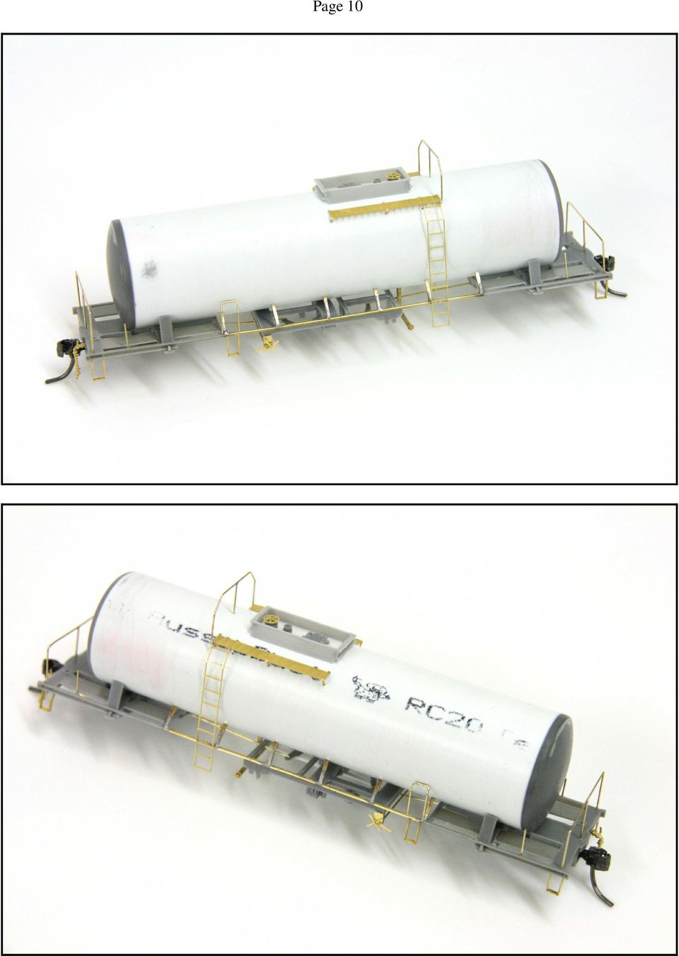
10 Page 10
11 Page 11 InFront Models hopes you enjoyed building this kit. The McWillams RTC kit was released at the AMRA Liverpool exhibition on 5 October This kit has been limited to a total of 200 units. It is envisaged that there will be no further production of this kit.

Instructions: General American 8,000 Gallon Acid Tank Car Kit 12/2014
 Instructions: General American 8,000 Gallon Acid Tank Car Kit 12/2014 Thank you for purchasing the Tangent Scale Models General American 8,000 Gallon Welded Acid Tank Car Kit! A few quick notes before
Modular Locomotive System Instruction Manual for HBK8 George Body Kit
 Modular Locomotive System Instruction Manual for HBK8 George Body Kit Roundhouse Engineering Co. Ltd. Units 6-10 Churchill Business Park. Churchill Road, Wheatley. Doncaster. DN1 2TF. England. Tel. 01302
MGB Chrome Bumper Conversion
 MGB Chrome Bumper Conversion Installation Instructions For 1974 1/2-1980 MGB This kit requires cutting, welding, and painting. Professional installation recommended. Note: Every MGB body is slightly different
Instructions: General American Dry-Flo Covered Hopper Car Kit 9/2014
 Instructions: General American Dry-Flo Covered Hopper Car Kit 9/2014 Thank you for purchasing the Tangent Scale Models General American Dry-Flo Covered Hopper Car Kit! A few quick notes before starting:
Modular Locomotive System Instruction Manual for HBK5 Billy Body Kit
 Modular Locomotive System Instruction Manual for HBK5 Billy Body Kit Roundhouse Engineering Co. Ltd. Units 6-10 Churchill Business Park. Churchill Road, Wheatley. Doncaster. DN1 2TF. England. Tel. 01302
TopSky DLG Installation Manual
 TopSky DLG Installation Manual Attention: Because after the compound materials solidify, there will be ammonia iris on the surface, which affect the bonding strength afterwards. Please polish with sandpaper
Build a Junior Solar Sprint Model Car Kit Materials: 1 PITSCO Ray Catcher Sprint Kit or Solar Made Junior Solar Sprint Kit 1 White Sheet of Plastic
 Build a Junior Solar Sprint Model Car Kit Materials: 1 PITSCO Ray Catcher Sprint Kit or Solar Made Junior Solar Sprint Kit 1 White Sheet of Plastic Coated Paper 2 Balsa Sheets (10-1/2 x4 x3/16 ) 2 Alligator
IMPORTANT INSTALLATION GUIDE VALENCIA SQUARE CORNER SHOWER READ ALL INSTRUCTIONS CAREFULLY BEFORE STARTING THE INSTALLATION
 INSTALLATION GUIDE VALENCIA SQUARE CORNER SHOWER SEALANT REQUIRED TO COMPLETE THIS INSTALLATION: (Not supplied) Sika Sikasil NG (Arctic White) To seal the WHITE shower door and returns to the shower tray.
Low Cost Heliostat Assembly Kit for High Schools
 Low Cost Heliostat Assembly Kit for High Schools Phillip Daniel Supervisor: Rockwell International Assistant Professor Alexander Mitsos Department of Mechanical Engineering Massachusetts Institute of Technology
How to Build a Poker Table
 How to Build a Poker Table www.pokertablematerials.com 10-Person Poker Table- 96 x 48 These are step by step instructions for building a poker table. The table will measure 48" x 96" and have a 4" wide
Things you need to assemble the tube actuator. Left to right. are small piece of masking tape, super glue,pen knife and small
 Things you need to assemble the tube actuator. Left to right are small piece of masking tape, super glue,pen knife and small crosspoint screwdriver. You will also need a few drops of light oil. Begin by
Jeep Wrangler Diagnosis & Repair Manual Water Leaks
 Jeep Wrangler Diagnosis & Repair Manual Water Leaks Rev. A General Notes 1. This manual applies to all Jeep models: 2/4 door & Hard/Soft Top 2. Before testing the vehicle, perform a review of the top system.
VICTORIAN RAILWAYS 'W' CLASS PASSENGER CAR
 C/- P.O. Rhyll, Victoria, 3923. VICTORIAN RAILWAYS 'W' CLASS PASSENGER CAR Prototype Notes The 58' clerestory roofed corridor passenger cars represented by this kit were introduced into Victorian Railways
DIY CABINET REFACING INSTALLATION GUIDE
 DIY CABINET REFACING INSTALLATION GUIDE CABINET REFACING INSTALLATION Are you ready to reface your outdated cabinets? This guide will show you how to install your new Facelifters Cabinet Refacing Products
How to Build Your Own CornHole Game
 How to Build Your Own CornHole Game DIMENSIONS Here is a diagram with the basic measurements for the Cornhole board game. SUPPLIES 1/2 thick sheet of plywood one 4 x4 or two 2 x4 s 8 long 2 4 s (4) 4 1/2
www.cornholesupplies.com
 www.cornholesupplies.com How To Build Regulation Cornhole Boards Home of the Original Cornhole Bags and Boards Supply List: 1-4' X 8' Piece of Plywood (pre sanded) 4-2" X 4" X 8' Studs (2 by 4s make sure
1/35 20t Russian platform railcar. contains 1 highly detailed and accurate model
 1/35 20t Russian platform railcar contains 1 highly detailed and accurate model 180 resin parts 70 PE parts + plastic parts and wires needed for assembly decals for 4 various cars (1 in German service)
3D Print Link's Hylian Shield
 3D Print Link's Hylian Shield Created by Ruiz Brothers Last updated on 2015-07-14 04:20:12 PM EDT Guide Contents Guide Contents Overview Parts, Tool & Supplies 3D Printing 3D Printed Parts Slicer Settings
30a. 31a. 30b 12. 31b. 29a 28a 1/48SCALEHEMSDAUPHIN PAGE2/10
 9 11 10 43 42 49 50 32 7 51 52 48 58 5 6 8 59 2 3 4 1 24 30a 31a 30 30b 12 31b 31 28 13 29 29a 28a 1/48SCALEHEMSDAUPHIN PAGE2/10 38 82 38f 85 84 86 83 37d 35 38a 37 60 17 21 20 16 15 87 27 34 40c 36b 36a
BUILDINGA 1/10 SCALE FLATBED TRAILER
 VOLUME 1, ISSUE 1 BUILDINGA 1/10 SCALE FLATBED TRAILER BUILT, DESIGNED & WRITTEN BY NATHAN MYERS MATERIALS: FEATURES: While the design was kept simple to allow anyone to be able to build their own trailer,
Gear PEPSI CAN STOVE INSTRUCTIONS
 Gear PEPSI CAN STOVE INSTRUCTIONS [NOTE: Updated Instructions are now available. The new stove is less likely to develop flame leaks and the fuel/air mixture is improved. Instructions for a simmer ring
Wren Kitchens Installation Tips... 3. Carefully check your kitchen delivery... 4. Measuring out and marking up... 5. Fitting the base cabinets...
 tra 1 Index Wren Kitchens Installation Tips... 3 Carefully check your kitchen delivery... 4 Measuring out and marking up... 5 Fitting the base cabinets... 6 Fitting the corner cabinets... 7 The 972mm or
Installing Window and Door Mouldings
 Installing Window and Door Mouldings About Window and Door Mouldings The trim around windows and doors greatly influences the look and style of your interior. They also bridge the gaps and cover spaces
SILVER WINGS 1/32 GLOSTer gladiator Mk1/mk2 build guide
 SILVER WINGS 1/32 GLOSTer gladiator Mk1/mk2 build guide Parts Cleanup As with other Silver Wings kits, parts cleanup is fairly simple, and due to the soft resin they use for their kit, a sprue cutter can
Permanent Magnetic Generator Construction Manual
 Permanent Magnetic Generator Construction Manual http://hojomotor.com Our Team Doing an On-site Assembly in Peru http://hojomotor.com Section 1) Introduction This manual describes how to build a 'permanent
2. This is a close up of a typical area where the rocker is rusted out leaving holes under where the rocker moulding would be..
 ROCKER PANELS 55,56,57 CHEVY REPLACEMENT Do not throw away any pieces when you first remove them. There are many supports that are not reproduced and will need to be used again. When disassembling try
EH-20 20m antenna. By VE3RGW
 EH-20 20m antenna By VE3RGW Equivalent circuit of EH-20 (prototype 2A) antenna system. Upper cylinder Lower cylinder Ground Counter pose Phasing coil Impedance transformer and tune circuit Tune coil Feed
A&A CORVETTE PERFORMANCE C6 BOOST & FUEL GAUGE INSTALLATION INSTRUCTIONS
 A&A CORVETTE PERFORMANCE C6 BOOST & FUEL GAUGE INSTALLATION INSTRUCTIONS 1. Check your gauges before you take them out of the packaging to make sure they are at 0 (zero) psi for both boost and fuel pressure.
Gate Leg Drop Leaf Table Plans
 Preparing the table top blanks: Cut and glue enough 3/4 stock to make three panels 40 long by 24 wide (they will be cut to final size at a later time). While the glue dries we will work on the legs. Preparing
Assembly GUIDE. display wine cellar kits. Required. Suggested. Questions? 888.373.6057. or visit wineracksamerica.com
 Page 1 Middle Ladder End Ladder Display Tray Screwless Connector Package Contents * All models follow the same assembly procedure varying only in the number of middle ladders your rack will require. Depending
Standard Sleep Pod Side Entry Assembly Instructions
 Standard Sleep Pod Side Entry Assembly Instructions www.podtime.co.uk [email protected] Working House Ltd How to assemble your pod Pod assembly onsite is a relatively simple exercise for two people
DETACHABLE WINDSHIELD AND DOCKING HARDWARE KIT
 -J00 REV. 00-- DETACHABLE WINDSHIELD AND DOCKING HARDWARE KIT GENERAL Kit Number -A, 0-, -, 0-, -, - 0, -0 Models These kits fit and later FXST, FXSTB, FXSTC, and and later FXDWG Harley-Davidson model
Electrical Wiring Technical Bulletin
 Electrical Wiring Technical Bulletin Overview In general, SIP construction is easier and more cost effective when things are planned and thought out before the panels are manufactured. This process will
Wine Rack & Glass Storage Bench Chris Gardner
 Wine Rack & Glass Storage Bench Chris Gardner Quantity Length Width Material Part 2 48 16 3/4 birch plywood top, bottom 2 14 16 3/4 birch plywood sides 2 14 13 3/4 birch plywood support dividers 2 3 15
Ladder Shelf Plans Final dimensions: 25 L x 21 W x 72 H
 Ladder Shelf Plans Final dimensions: 25 L x 21 W x 72 H Copyright 2011. MLCS Woodworking. Page 1 Router bits and supplies needed: 3/8 Rabbeting bit (#10691) 1 Bottom Cleaning bit (#7941) Top and Bottom
Wall Mount Installation and Use
 Wall Mount Installation and Use 1. Introduction The Wall Mount works the same way for all Touchfire cases - the one or two row magnet strip on the back of the case is magnetically attracted to the Wall
Making a Rain Barrel at Home
 Making a Rain Barrel at Home This is a step by step guide to making your own rain barrels. Constructing a rain barrel is a pretty simple project that helps conserve water and protects the environment.
IMPORTANT INFORMATION
 Curved Quadrant Instruction Manual CQ IMPORTANT INFORMATION Toughened glass is completely safe for use in our shower enclosures and bath screens; providing our products are installed according to our guidelines.
Technical data. Assembly: Introduction. Before starting construction. Equipment needed. Glider or Electro Glider?
 Palio pro S2084 Technical data Wing span: Lenght: Weight: Wing area: Wing loading: El. Motor/ no. of cells: Controls: Introduction 2150 mm 1150 mm 1120 g 1860 g 42 dm2 27 g/dm2 44 g/dm2 600 / 7-8 cells
Important Information
 Single Door Quadrant Instruction Manual ESQ Important Information Toughened glass is completely safe for use in our shower enclosures and bath screens; providing our products are installed according to
Installation Instructions
 READ BEFORE INSTALLING UNIT For Through-the-Wall Air Conditioners To avoid risk of personal injury, property damage, or product damage due to the weight of this device and sharp edges that may be exposed:
IN00419 (rev A) Aqua 6 Glide Quadrant and Off-set Quadrant Enclosure
 Aqua 6 Glide Quadrant and Off-set Quadrant Enclosure") IN00419 (rev A) Aqua 6 Glide Quadrant and Off-set Quadrant Enclosure Instruction suitable for both Quadrant & Off-set Quadrant variations. Instruction suitable for both Right and Left Hand fixing variations
IN00419 (rev A) Aqua 6 Glide Quadrant and Off-set Quadrant Enclosure Instruction suitable for both Quadrant & Off-set Quadrant variations. Instruction suitable for both Right and Left Hand fixing variations
UB1 AIR CONDITIONING UNIT INSTALLATION INSTRUCTIONS
 UB1 AIR CONDITIONING UNIT INSTALLATION INSTRUCTIONS INSTALLATION INSTRUCTIONS: Carefully read these instructions before installing your new air-conditioner. AUSTRALIAN AUTOMOTIVE AIR AL00500054E 1 Table
Installation Instructions
 Installation Instructions 1. Position the unit onto bridging packers. These keep the unit away from any water sitting inside the frame. 2. Centralise the unit within the frame and pack the edges with appropriate
Installation instructions, accessories - Handsfree for cellular phone, system B, entry level
 XC90 Section Group Weight(Kg/Pounds) Year Month 3 39 0.5/1.1 2006 07 XC90 2003, XC90 2004 IMG-249663 Page 1 of 18 Required tools A0000162 A0000163 IMG-239664 M0000232 IMG-253123 IMG-252223 Page 2 of 18
www.rkeducation.co.uk solutions for teaching and learning
 Teacher Notes Transistor Astable Project Introduction The aim of this 7 week (2hr lessons) project is to design and manufacture an electronic product based on the transistor astable circuit. The project
How To Replace A Reverse Osmosis Water Tank
 ALL MODELS REVERSE OSMOSIS WITH NONAIRGAP FAUCET 1. Read all instructions carefully before starting installation. 2. Find the cold water line beneath your sink. The cold water is typically on the right.
Jeep Wrangler Diagnosis & Repair Manual Water Leaks
 Jeep Wrangler Diagnosis & Repair Manual Water Leaks Rev. A General Notes 1. This manual applies to all Jeep models: 2/4 door & Hard/Soft Top 2. Before testing the vehicle, perform a review of the top system.
Star Trek: The Motion Picture Tricorder
 #PRP1786 Star Trek: The Motion Picture Tricorder Prop Kit Assembly Manual For the first time ever, Roddenberry.com is pleased to introduce the Star Trek: The Motion Picture Tricorder build it yourself
INSTALL INSTRUCTIONS KK-C-HVAC-1 HVAC UNIT 2003-2014 CHEVROLET/GMC VANS FOR
 INSTALL INSTRUCTIONS KK-C-HVAC-1 HVAC UNIT 2003-2014 CHEVROLET/GMC VANS FOR (For NEW 2007 ALL WHITE KWIK-KITS ONLY) Warning do not attempt to install A/C units unless you are experienced with servicing
GENUINE PARTS INSTALLATION INSTRUCTIONS
 GENUINE PARTS INSTALLATION INSTRUCTIONS DESCRIPTION: Illuminated Kick Plate APPLICATION: Rogue (2011) PART NUMBER: 999G6 GX010 KIT CONTENTS: Item A B C G H QTY 1 1 1 D 1 E 1 F 3 15 6 Description Kick Plate,
majestic install ation guide barcelona three sided enclosure 24mm surface mounted wall channels and underframe to base
 majestic install ation guide barcelona three sided enclosure 24mm surface mounted wall channels and underframe to base These Instructions are for a left and right handed unit. The diagrams show a left
Cedar Cottage Doghouse Plans
 Overlapping cedar shingles add an element of charm to this medium size doghouse. The walls, floor, and trim are constructed of solid cedar, making it naturally weather resistant and provides excellent
CAST IRON THE BASICS. Heatline - Cast Iron Radiators SMOOTH FLAT FILE TO REMOVE ANY SWARF. ONE TIME. ASSEMBLY. JOINTS SHOULD BE TIGHTENED.
 CAST IRON THE BASICS 1. DO NOT LIFT ON YOUR OWN. 2. ONLY LIFT THE RADIATOR VERTICALLY. 3. DO NOT LIFT MORE THAN 8/10 SECTIONS AT ANY ONE TIME. 4. POSITION THE RADIATOR BEFORE FINAL ASSEMBLY. 5. THIS PRODUCT
Back-Up Camera Installation Guide
 Hz Hz In This Guide: Back-up camera installation requires connecting power wiring to the existing reverse lighting circuit and adding a chassis ground, as well as routing a video signal cable to the front
Installation Instructions
 Installation Instructions READ BEFORE INSTALLING UNIT For Low Profile Window Air Conditioner INSTALLATION WARNINGS AND CAUTION Carefully read the installation manual before beginning. Follow each step
WINDOW REPAIR MANUAL & REFERENCE GUIDE
 WINDOW REPAIR MANUAL & REFERENCE GUIDE TABLE OF CONTENTS DOUBLE HUNG & SINGLE HUNG PARTS 4-5 CASEMENT PARTS 6 SCREEN PARTS 7-8 HOW TO REMOVE TILT-IN SASH 9 HOW TO REMOVE A BALANCE 10 HOW TO INSTALL BALANCE
Go-kart for little race-drivers
 Go-kart for little race-drivers Drill and drive. Go-kart What it lacks in speed, it more than makes up for in fun: the go-kart will excite little race-drivers. 1 Introduction It s only a go-kart, but it
Installation Instructions For Slider Casement Air Conditioners
 Installation Instructions For Slider Casement Air Conditioners NOTE: These instructions describe installation in a typical wood framed window with a wood SLIDE-BY sash, or installation in a metal CASEMENT
Installation Instructions
 Installation Instructions One-Piece Deep Wall Sleeve For Use with Packaged Terminal Units Please read these instructions completely before attempting installation. NOTE: Ensure that the unit is only installed
COMPLIMENTARY WOODWORKING PLAN
 COMPLIMENTARY WOODWORKING PLAN Adirondack Chair This downloadable plan is copyrighted. Please do not share or redistribute this plan in any way. It has been created for Wilton Tools, a division of WMH
98 Turbine Vulcan Build photos
 98 Turbine Vulcan Build photos Just some of the useful tools needed plus a quality razor plane FUSELAGE Note: Fitting parts back to front is an easy mistake to make with this build, so mark all part with
VW Caddy W21-760-3503 INSTALLATION INSTRUCTIONS
 Unit 626 Kilshane Avenue, North West Business Park, Ballycoolin, Dublin 15, Ireland Telephone: +353 1 8612 632, Fax: +353 1 8612 647, email: [email protected] www.driveriteltd.com VW Caddy W21-760-3503
HOW TO MAKE A MOTOR BRACKET
 HOW TO MAKE A MOUNTING BRACKET FOR AN ELECTRIC MOTOR Often, brackets supplied with purchased items (e.g. electric motors or servos) are not ideally suited for fitting into our models or they are not supplied
Black Wolf POCKET BILLIARD TABLE INSTALLATION MANUAL. SERVICE DEPARTMENT P.O. BOX 68 BRISTOL, WI 53104
 Black Wolf TM POCKET BILLIARD TABLE INSTALLATION MANUAL www.brunswickbilliards.com SERVICE DEPARTMENT P.O. BOX 68 BRISTOL, WI 53104 51-905710-000 SEPTEMBER 2010 NOTE: Please use the instructions in this
1958-64 WINDOW CHANNEL, WEATHERSTRIP & WHISKER STRIP REPLACEMENT FOR 2-DOOR SEDANS
 By Denny Williams Photos by Denny Williams 1958-64 WINDOW CHANNEL, WEATHERSTRIP & WHISKER STRIP REPLACEMENT FOR 2-DOOR SEDANS Denny Williams - Technical Writer Denny is first and foremost a dyed-in-thewool
Table of Contents. www.hunterfan.com. What to Expect with. Preparation. Tools Needed. Wiring. Hanging the Fan. Blades. Motor Housing.
 www.hunterfan.com Table of Contents What to Expect with Your Installation 30 inches Hanging the Fan Wiring 8 Maintenance, Operation & Cleaning Light Kit 13??? 14 1 9 Troubleshooting 11 5 Blades Motor Housing
Vinyl Greenhouse Window Page 2 of 6 New Contruction Installation Instructions
 New Construction Installation Instructions EPLACEMENT Installation Instructions Page 2 of 6 New Contruction Installation Instructions 1. Frame rough opening equal to window call out size. ough opening
INSTALLATION INSTRUCTIONS. 6108 Air Spring Kit 2011+ Ford F250 Single Wheel 4WD 2011+ Ford F350 Dually 4WD (2011 F350 Single Wheel 4WD use p/n 6113)
") INSTALLATION INSTRUCTIONS 6108 Air Spring Kit 2011+ Ford F250 Single Wheel 4WD 2011+ Ford F350 Dually 4WD (2011 F350 Single Wheel 4WD use p/n 6113) Thank you for purchasing a quality Hellwig Product. PLEASE
INSTALLATION INSTRUCTIONS 6108 Air Spring Kit 2011+ Ford F250 Single Wheel 4WD 2011+ Ford F350 Dually 4WD (2011 F350 Single Wheel 4WD use p/n 6113) Thank you for purchasing a quality Hellwig Product. PLEASE
INSTALLATION INSTRUCTIONS. 6111 Air Spring Kit 2011+ Ford F250/F-350 Single Wheel 2WD 2011+ Ford F350 Dually 2WD IMPORTANT NOTES
 INSTALLATION INSTRUCTIONS 6111 Air Spring Kit 2011+ Ford F250/F-350 Single Wheel 2WD 2011+ Ford F350 Dually 2WD Thank you for purchasing a quality Hellwig Product. PLEASE READ THIS INSTRUCTION SHEET COMPLETELY
2&3 SECTION LOFT LADDER
 TWIST CATCH ASSEMBLY A4 A2 A1 A3 A7 A6 A5 2&3 SECTION LOFT LADDER Images feature the 3 section loft ladder, but the same instructions apply to both 2 & 3 section ladders Installation and Operating Instructions
Power Window/Power Lock Installation. To begin with you will need all the parts listed below:
 Power Window/Power Lock Installation To begin with you will need all the parts listed below: From Donor Fiero: Fiero power window regulators Power window motors (Generic GM type part) -motors are riveted
6mm Two Door Offset Quadrant
 Installation Guide 6mm Two Door Offset Quadrant 226MBJ 0914RN Offset Quadrant 226MBJ.indd 1 07/08/2015 14:03 Cu w Before you Start Please read this Installation Guide fully. Although these instructions
Industrial Strength Rocket Launcher
 Industrial Strength Rocket Launcher Description: Instructions for the construction of an industrial strength rocket launcher for use with paper rockets. Materials: Schedule 40 PVC piping and bushings from
Barewood Octagon and Elongated Windows Installation Instructions
 Step-by-step instructions to a beautiful window. Measuring and Installation of your new window from Century Specialty Windows couldn't be easier with our step-by-step instructions. Quality, function and
Slide the new steering column shaft through the steering column from the driver compartment.
 Slide the new steering column shaft through the steering column from the driver compartment. Push the column shaft through the steering column until the machined end is out past the column lower bushing.
Lunette 2 Series. Curved Fixed Frame Projection Screen. User s Guide
 Lunette 2 Series Curved Fixed Frame Projection Screen User s Guide Important Safety and Warning Precautions Please follow these instructions carefully to ensure proper maintenance and safety with your
A Telescoping Hive Cover
 A Telescoping Hive Cover The telescoping hive cover is what keeps the weather and elements out of your bee hive; it is like the roof of your house (Figure 1). Commercial hive covers typically feature a
Drum set : Assembly Instructions
 Front Right side View of completed model Back Left side A drum set is a collection of various types of drums, cymbals and other percussion instruments that are lined up in a formation that makes them easily
Installation Instructions
 READ BEFORE INSTALLING UNIT For Slider Casement Air Conditioners To avoid risk of personal injury, property damage, or product damage due to the weight of this device and sharp edges that may be exposed:
!!!!!! !!! Decra Plus DPSW010 DPSTW011 DPSW012 DPSW013 DPSW014 DPSW015 DPSW016 DPSW020 DPSW021 DPSW024 DPSW030 DPSW031 DPSW035 DPSW030 DPSW031 DPSW035
 Decra Plus Drawing no DPSW010 DPSTW011 DPSW012 DPSW013 DPSW014 DPSW015 Description Shown In Decra Brochure Most Commonly Used Detail t~êã=oççñ=b~îéë=aéí~áä=b~îéë=lîéêü~åö=táíü=fåëìä~íéç=c~ëåá~=~åç=pçññáí
Window Installation Instructions
 Caution The correct installation methods of windows in full frame or insert applications is critical towards achieving the tested performance of the window and longterm enjoyment and energy savings for
Stair Parts Installation. Tricks
 Stair Parts Installation Tips & Tricks Introduction Your DIY staircase guide Welcome to the Stairpart home installation guide. Your stairway is both a functional and focal point in your home, so keeping
Curved Quadrant Instruction Manual
 Curved Quadrant Instruction Manual Consumer Guarantee - Please make sure the purchaser/end user completes and returns the Guarantee card which is enclosed with this product. Failure to validate the Guarantee
Assembly Instructions Basic Folding-Leg Box Frame Style
 Assembly Instructions Basic Folding-Leg Box Frame Style Basic Folding Leg Cornhole Board Concept 1 2 12 3 1 2 3 15 16 4 1 4 52 9 R1 3 4 6 21 48 12 1 4 Bolt Washer 9 13 16 35 Washer Double Nut CornholePlayers.net
Firewall Cover Installation Instruction Sheet
 Firewall Cover Installation Instruction Sheet Please Read Carefully Our Firewall cover is designed to fit on the stock strut brace. If you have an aftermarket strut brace than it is you re responsibility
Integral Kit Instructions
 Integral Kit Instructions For Fisher & Paykel Cabinet widths of 525, 635, 680, 790 mm wide For curved door Models Series B, C, D & G Manual 814980 Updated August 2008 IMPORTANT If your refrigerator has
STEADYfast Stabilizer Installation Notes Fifth Wheel and Travel Trailers 11/23/13
 STEADYfast Stabilizer Installation Notes Fifth Wheel and Travel Trailers 11/23/13 (See Supplemental Instructions for trailers with heavy duty round footplates and/or Power Leveling Systems) PHONE SUPPORT
Installation information. METTLER TOLEDO MultiRange Floor scales / Pit scales
 Installation information METTLER TOLEDO MultiRange Floor scales / Pit scales KC300/KCS300 KC600/KCS600 KD600/KD1500 KE1500/KE3000 KES1500/KES3000 KG3000/KG6000 KN1500 Floor scales / Pit scales Contents
Make sure all tubes are installed to your satisfaction BEFORE finish welding!!
 INTRODUCTION: This S&W Roll Bar or Roll Cage performs both a safety and performance function. As a safety device, the main hoop of the cage protects the driver from impact. The rear braces and side bars
Hive Top Ventilation Shims
 Hive Top Ventilation Shims When preparing your bee hives for the winter, it is very important to provide for ventilation at the top of the hive. Through out the winter, the bees are expelling a lot of
Premier & Deluxe 3-Season Room Sliding Glass Door
 DTSSGD-11 Premier & Deluxe 3-Season Room Sliding Glass Door Installation Instructions Screen Door Seal Left Side Track Top Track Assembly Right Side Track Right Side Trim Sliding Glass Door Sliding Screen
1/5 PIPER J-3 CUB. Before commencing assembly,please read these instructions thoroughly. Wing Span:84. 0 in / 2130 mm
 INSTRUCTION MANUAL Before commencing assembly,please read these instructions thoroughly. 1/5 PIPER J-3 CUB 1/5 PIPER J-3 CUB Wing Span:8. 0 in / 130 mm Wing Area:968 sq in / 6. 5 sq dm Flying Weight:8.
FL ADJUSTABLE RIDER BACKREST MOUNTING HARDWARE KIT
 -J070 REV. 0-0-0 FL ADJUSTABLE RIDER BACKREST MOUNTING HARDWARE KIT GENERAL Kit Number 9-09A Models For model fitment information, see the P&A Retail Catalog or the Parts and Accessories section of www.harley-davidson.com
Elo Touch Solutions Wall-mounting Kit for the 5501L IDS Touchmonitors
 Installation Manual Elo Touch Solutions Wall-mounting Kit for the 5501L IDS Touchmonitors SW602206 Rev B Table of Contents Chapter 1: Safety Warning... 3 Chapter 2: Kit Contents... 4 Included in Kit...
Brick Veneer Construction
 Brick Veneer Construction Check list of suggested tools & support items Claw hammer Tape measure 3/4" [19 or 20] Wood chisel Wood or plastic shims Pry bar Utility knife Caulking and caulking gun Power
Rebuild Instructions for 70001 and 70010 Transmission
 Rebuild Instructions for 70001 and 70010 Transmission Brinn, Incorporated 1615 Tech Drive Bay City, MI 48706 Telephone 989.686.8920 Fax 989.686.6520 www.brinninc.com Notice Read all instructions before
Have fun, nevertheless!
 Nanomum The Nanomum is a small pusher gyro for flying indoors or outdoors in very calm weather. It's got a dc head and is easy to build and easy to fly - I hope. Specs: AUW 70 g / 2.5 oz. Rotor diameter:
Rooflight INSTALLATION INSTRUCTIONS
 INSTALLATION INSTRUCTIONS Rooflight These instructions should be used for: Installing Permanent Trickle Ventilation: Constructing & Waterproofing a Timber Upstand Curb: Installing & Waterproofing Proprietary
Fiberstars Lighted Laminar Flow Fountain Installation Manual
 Fiberstars Lighted Laminar Flow Fountain Installation Manual 79-15037-00 REV Xx http://www.fiberstars.com Page 1 of 8 SAVE THESE DIRECTIONS! These directions are provided to ensure the proper installation