SILVER WINGS 1/32 GLOSTer gladiator Mk1/mk2 build guide
|
|
|
- Lindsey Randall
- 8 years ago
- Views:
Transcription
1 SILVER WINGS 1/32 GLOSTer gladiator Mk1/mk2 build guide Parts Cleanup As with other Silver Wings kits, parts cleanup is fairly simple, and due to the soft resin they use for their kit, a sprue cutter can even be used to snip most parts from their pour stubs. After that, a few scrapes with the Xacto knife and/or sanding stick and the part is ready for use. With these kits, since there are no part numbers to worry about, I like to clean up all the parts and then begin the build. Any parts can be painted as appropriate after cleanup and before assembly as well. A few things to note when preparing your kit parts for use: The lower wings have a couple of excess resin rods on the top tips (see photo 1), these must be removed as the outer wing should be smooth.

2 The ailerons on my kit did not want to fit to the wings at all. Upon investigating, they seem to have had a slight shift during molding, as there was a slight step inside each of the hinge attachment points. Cleaning these up led to a much better fit. The windscreen for either version (Mark I shown in photo 2) is too splayed out at the base. To fix, simply pour hot water on the windscreen and bend inwards to get the correct shape. Once complete, I recommend dipping all the canopy parts in future, as it will greatly improve their transparency (see photo 3).
 is too splayed out at the base.")
3 The engine block has a pour block on the backside, and you should only remove the fins, leaving the center round part as this will be needed to attach the engine/cowl assembly to the fuselage (see photo 18 referenced later in the guide) The lower cowl piece and upper appear to be different sizes. However, once assembled and fitted to the exhaust collector ring (the round front cowl part) they will assume the correct shape. Also note that the lower cowl has the cutout for the carb intake common to the Mk.II Gladiator, which is not always correct for a Mk.I airframe. Consult your references for the markings you plan to do, and if necessary, the cutout can be filled with a piece of sheet styrene (do so after fitting to the lower cowl to the front exhaust collector ring to get the correct shape). My cockpit frames were a bit twisted and broken in some spots, so I repaired the breaks before assembly. Note that the shape of these frames should bow out in the middle. The lower cowl ring has two pins that are used to fit it to the exhaust collector ring, take care not to remove them when cleaning up the pour stubs that are near them. Also be sure to take care when removing the pour stubs from the front edge of both the upper and lower cowl, in order to keep a straight edge. The exhaust collector ring has two bulges under two of its three pour stubs so take care not to sand them down too much either. The starboard side of the seat needs some cleanup from the pour stub, but try not to destroy the lip surrounding the seat pan. The engine cylinders have some slight seams on the sides that may require cleanup, however any that you miss will likely not be visible on the finished model without searching really hard for them. Be sure not to damage the exhaust tubes that face forward on each cylinder head. Also note that the pushrods need to be cut carefully, and err on cutting them too long as if you just snip them off like I did, you will find that many of them are a tad short. The kit provided Fairey-Reed propeller will need some work to make it useable, as it is the same thickness on both edges of the blade, and lacks most of the twist at the base of the blade that is visible in many photographs (it s just started on the kit part). Fortunately, you can sand the trailing edge thinner easily (since this is softer resin), and the twist at the base can be enhanced after heating the blade in hot water. There will be some extra parts depending on which version and airframe you wish to model, so not all parts will require cleanup if you know which version/airframe you plan to build. I also noted some spare duplicates of some fragile parts in my kit, which is a nice touch by Silver Wings. Engine Assembly Prior to assembling the engine, you should drill three 1mm (#60 drill bit) holes, one each at the 12:00, 4:00 and 8:00 positions in the gear cover (see photo 4 for location) for the cowl brace (referred to in the instructions as prepare on your own ). This brace is actually 3 parts on each brace, one rod from the gear cover to the exhaust collector ring (the front part of the cowl) and two thinner rods from the each side the cylinder head base to the main brace, attaching just below where the main brace meets the exhaust collector. For purposes of this build, I just added the three 1mm rods. Once you have drilled your holes, engine assembly begins with the cylinder heads. Attach each one, making sure it is facing directly forward. You can check your work by putting them up against the exhaust collector ring. After this, you can attach the pushrods in place; each has a pad on the engine block and the cylinder head to aid in placement. If you are building a Mk1 airframe, you should attach the two downward pointing tubes referred to in the instructions (see photo 4 for location assistance) Finally, attach the breather tubes to the back of the engine block and cylinder heads.

4 Interior Subassemblies Assemble the throttle as shown in the instructions, the two handles are provided in resin, and just need some careful cleanup. Paint the back of the Mk.I or Mk.II instrument film white. On my kit, the Mk.I instrument panel was almost 1mm too wide, so either trim it now, and/or you can thin the cockpit sidewalls where they contact the instrument panel to help ensure a good fit. My references indicate that the panel (either Mk.I or Mk.II) should be black (and it is in many photos), however some preserved airframes show them in a red-brown Bakelite color. Once the white paint is dry, you can attach the film to the back of the appropriate panels. Silver Wings also provides a nice brace for either panel, which makes it much easier to attach to the completed cockpit. The brace should be interior green, and once dry, attach your PE panels in place as appropriate. Assemble the ammunition box (two parts to the base plate), but do not attach the chutes until you are ready to close the fuselage in order to get them at the correct angle to meet the gun breeches. Assemble the rudder pedals, and attach them to the floorboard. For best results, I bent the PE toe straps around the metal end of a paintbrush, as the PE buckle area does not want to bend as nicely as the rest of it. Cleanup and attach the compass pedestal to the floorboard. If you have a decal for a compass, you can apply it after painting for a more realistic look. I left my control stick off until after the cockpit was assembled to make it easier to place the floorboard in the cockpit framing. I found it easier to attach the two brackets to the appropriate sides of the seat, rather than trying to get them in the exact position on the 24mm rod as indicated in the instructions. After the two brackets had set, I put the rod through the appropriate holes, with the bell crank between them. I then centered the bell crank on the rod between the brackets and glued it into position. I did not glue the rod to the seat brackets, as that will allow me
 should be black (and it is in many photos), however some preserved airframes show them in a red-brown Bakelite color.")
5 to position the seat in the center of the cockpit later (see photo 5). You may also want to attach the seat harness straps to the bottom of the seat before placing it in the fuselage later. You can attach the two cylinders and battery to the rear floorboard. Photo 6 shows the completed subassemblies (including the cockpit frame and engine)

6 Cockpit Assembly The Gladiator cockpit is primarily interior green with throttle, etc. in black. Assembling the interior for this kit is relatively straight forward, and like other Silver Wings kits, getting the cockpit framing assembled as straight as possible is key. I began building up the interior subassemblies by working on the cockpit framing. For best results, I recommend the following order: Using square styrene strip, cut two 22mm pieces, one 17mm piece and one 24mm piece. Align the two side frames with each other, and glue the center H frame to each side in the position indicated by the instructions. Immediately glue the V frame to each side in the position indicated by the instructions (note that it should slant back slightly to align with the side frame), followed up the middle-front 22mm styrene piece and the 24mm styrene piece (note that this piece should be fitted immediately behind the sill flange area, otherwise your cockpit will be too wide) Double-check your alignment to ensure everything is square (note the cockpit should be narrower at the bottom than the top). Next, you can attach the front and rear floor pieces, followed by the two remaining upper styrene pieces (17mm and 22mm). See photo 7. Test fit your completed cockpit frame to the fuselage to ensure it fits properly. Now is a good time to attach the required parts to the fuselage side pieces (photo 8). I elected to omit the front bulkhead as test fitting showed that it was not necessary. Next assemble the remaining cockpit components to the frame. Start with the floorboard, which should rest on the V frame in the front, and the tabs on the side frames just above the H frame in the back.

7 Attach the bottom seat rod (with the seat) to the cockpit sidewalls, resting it on top of the tabs as indicated. I did not glue the top back part of the seat to the upper frame, allowing it to move forward for the time being (which will be helpful in installing the backplate later). Attach the trim wheel and the PE control lever assembly, as well as the throttle and round switch box as indicated by the instructions. Attach the fuel tank to the front floor, the ammo bin (dry fit in the fuselage side and use your installed MG's to get the correct fit) and the instrument panel appropriate for your model (see photo 9 and 10)
 and the instrument")
8 Fuselage Assembly Fuselage assembly is straightforward, as one would expect, simply insert the cockpit assembly between the fuselage halves and glue together. There are alignment tabs in the fuselage to help align the cockpit properly. I chose to leave mine "loose" and tacked it in place once the fuselage halves were together. Once your fuselage glue is set, you can clean up the seams. Moving your seat back forward (pivoting on the lower rod), insert the rear backplate, taking care to center it within the fuselage. Once the fit is correct, you can glue it into position, followed by the seat back once the backplate is set. If you are going to attach either of your side doors in the closed position, do so now. If either will be open, they can be added later. Next, attach the seat harness tray, and the upper seat harness straps (the tip of the harness should be just through the slot in the backplate), then attach the other side strap, and final cap with the small PE attachment plate. Finally, attach the two tensioning springs (PE7) to either side. Mine were a little long, so I trimmed them to fit. I then attached the gun sight frame pieces, followed by the gun sight with the appropriate film. Attach the front windscreen and rear canopy at this point being sure to center them on the fuselage. If you plan to have your main canopy closed, you should use it to get the proper position of the windscreen and rear canopy to optimize the overall canopy fit. Once dry, test fit the brace that attaches between the backplate and top of the rear canopy. I needed to sand mine slightly, and then attached it in position. (see photo 11 and 12) I then took the opportunity to drill out the cabane strut attachment points, after making a drill guide template (see photo 13).

9

10 Assemble the fuselage MG's and attach as indicated in the instructions. I believe that the longer MG barrels should go on the fuselage, but can't be sure (I used the shorter ones on the fuselage for this build - but the longer ones look too long on the wing). Bend parts PE14 into the correct curved shape (I used the handle of a paintbrush, and then bent the inner rear parts in past the vertical for the best fit) and attach as indicated (photo 14). Note that they highest part of PE14 should be just about flush with the fuselage.

11 Bend the radiator mat to fit the curve of the fuselage (I rolled an Xacto handle on mine to get the correct shape). Note that there should be a slight space between the mat and the fuselage. the kit has 4 raised attachment stubs molded to the fuselage. Test fitting the mat showed that these left what I felt was too large of a gap for my tastes, so they were sanded down slightly. I then glued the radiator mat into position. Attach the small rod (vent?) to the hole in the top of the fuselage as indicated in the instructions (see photo 15). Cowling Assembly You may want to pre-paint the interiors of the cowls and exhaust collector ring, and touch up as necessary after assembly. After studying the parts, I came up with the following assembly sequence to get the cowl together: Attach the lower cowl piece to the exhaust collector ring (the front of the cowl), taking care to get it aligned properly (see photo 16). Once dry, test fit the completed engine to the exhaust collector ring. You will likely have to apply some pressure to get a good fit - be careful not to press too hard or you may break some of the cylinder exhaust tubes (ask me how I know this)! Sand any cylinder exhaust pipes that do not fit properly. Once you are satisfied with the fit (and the engine is square to the exhaust collector ring), glue the engine to the exhaust collector ring using the exhaust tubes on the cylinders. Note that these pipes were welded to the exhaust collector ring on the real aircraft, so you do not need a perfect attachment, some superglue gel around the pipe to represent the weld is fine :) When dry, you can test fit the upper cowl piece. Mine was too big, so I sanded down each side of the cowl-tocowl attachment surfaces to the raised bracket points (see photo 17)

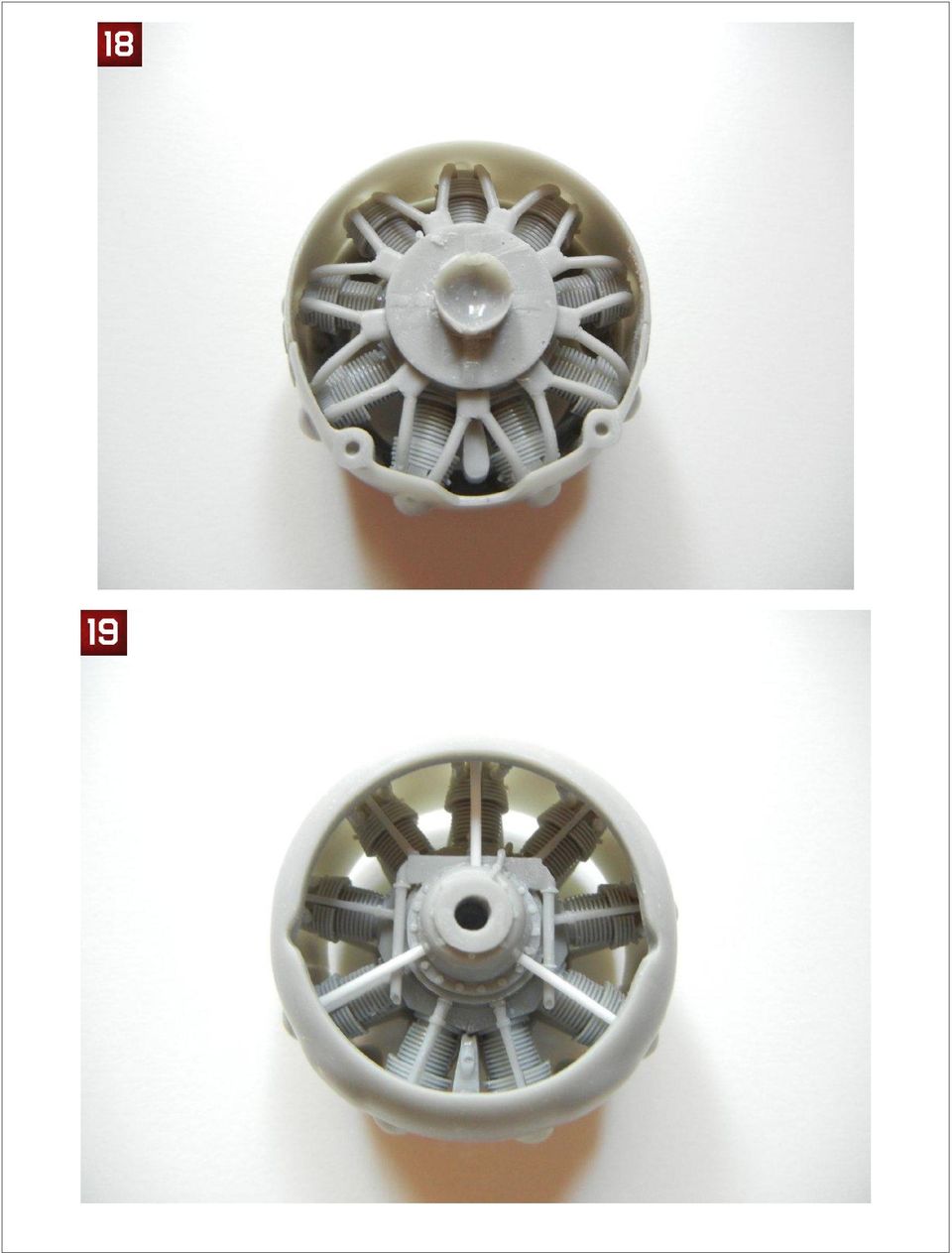
12 I then glued one side of the cowl-to-cowl mating surface, let set and then glued the opposite side. I then glued the remaining cowl to exhaust collector ring surface (see photo 18 and 19) Attach straps PE16 to each side of the cowl to complete the assembly. If desired, you can now paint your cowling and set the completed assembly aside until final assembly

13
14 Lower wings Drill out the wing strut attachment points using a drilling template (check the "Tips and How To's" section of the Silver Wings website ( for an article on making and using drilling templates). I placed my model on a piece of styrofoam and gouged out slot for the MG's on the bottom of each wing. Once I had a level surface, I glued the wings to the fuselage, using a 6mm spacer at the tips as indicated in the instructions to achieve the correct dihedral. (see photo 20) Attach the anti-skid plates (PE15) to each wing as indicated. You can attach the underwing MG barrels, or wait until after painting. Upper wings Before assembling the upper wings, I drilled out the cabane strut holes, and wing strut holes using drilling templates. I test fit the wing center section and cabane struts to the fuselage to ensure a good fit (see photo 21). Once satisfied with the fit, remove the wing center section and attach the outer wing sections. Place the wing parts on a flat surface, and glue the wings into position, using a 6mm spacer at the tips as indicated in the instructions to achieve the correct dihedral. I had some slight gaps on the bottom of the wing where the center and outer wing parts meet. I filled these with superglue (see photo 22) and sanded smooth once dry. I then made a homemade jig (see the Tips & How To's section of the Silver Wings site ( for an article on making your own simple jig) and began the process of attaching the upper wings. I sorted out the interplane struts, and found that one pair was ever so slightly longer than the other. As one of the longer pair has a round bump on the front, and the instructions indicate this one goes on the starboard side
 Attach the anti-skid plates (PE15) to each wing as indicated. You can attach the underwing MG barrels, or wait until after painting.")
15 front, I was able to then sort out which struts went where (the ever so slightly longer ones in front, and the others in the rear). I did note in test fitting that the curve of the resin part of the interplane struts do not match precisely the curve of the wing surfaces (see photo 23).

16 Fit each strut to its appropriate position on each mating surface, and trim the brass rod parts to ensure a good fit. When ready, mix up some epoxy and start attaching the struts to the fuselage and lower wings in their appropriate positions. When tacky, place the upper wing in position and secure it using your favorite jig to ensure proper alignment. Once the epoxy is dry, you can remove the upper wing and clean up any that oozed out where it should not be. At this point, you will want to use your favorite filler as necessary to get a perfect attachment point of the struts to their fuselage and lower wings. Once complete, mix up some more epoxy and attach the upper wing, securing it with your favorite jig (see photo 24).

17 Rear Empennage The rear empennage for this kit is very straightforward. The kit does provide the rear bell crank for the elevators, which are barely visible on the finished kit, so you should decide if you want to attach any control cables to them. You can also complete this step at any time after you have glued the fuselage together, depending on what you think will be easiest for you and the painting scheme you have chosen. Start by attaching the vertical stabilizer to the fuselage. Then attach the horizontal stabilizers, ensuring that everything is aligned properly. I noted a tight fit on the port side stabilizer, so I opened the holes slightly to aid in a good fit. Oddly, when I was attaching the horizontal stabilizers, I noticed that if I attached them one way, there was an angle across the backside of them, whereas the other way, the backside was straight. So, be sure to check before gluing that everything is straight. Now, attach the bell crank assembly to one of the elevators. Test fit to be sure that the bell crank will be more or less centered when looking at them from the slot in the rear. Then test fit to the other elevator, and trim as necessary to get a good fit while keeping them in the proper position. (See photo 25). If you have chosen to attach control cables, this will be an interesting exercise indeed! Attach the control horns to each side of the rudder as indicated in the instructions, and then attach the rudder into position as desired (see photo 26).

18 Final Assembly Now we are on the home stretch, and we have a model that looks pretty much like a Gladiator :) You should decide at what point you want to paint (and rig if desired) your model, and stop and do so when you have assembled the necessary parts. Now let's get those final bits attached! I started by test fitting the air intake tubes into the holes provided in the front of the fuselage. When I attempted to fit them with the engine/cowl assembly in place, I noticed the holes needed to be relocated, so I noted the correct position and drilled new mounting holes. Photo 27 shows one hole drilled in the proper position (lower and to the outside) on the left, while the two existing holes can be seen as well.

19 Next, I glued the main gear legs in position (be sure to select the proper legs for your choice of skis or wheels). I drilled out the mounting hole in the fuselage to make it deeper, and did not trim any of the brass rod to provide maximum strength. You should trim the brass rod where the wheel or skis will attach to ensure a proper fit. I attached the step using the three holes indicated in the port-side bottom of the fuselage, and attached the pitot tube to the port side front strut as indicated in the instructions. If your model was equipped with a radio, you can attach the antennae mounting pins on the rudder and upper wings. I trimmed 2mm off the attachment point of the carb intake, and glued it in position in the square hole provided in the bottom of the fuselage. Now we can attach the engine/cowl assembly to the fuselage. Once positioned, I then attached the two air intake tubes (see photo 28). Now we can attach the exhaust pipes. There is supposed to be a mounting pin towards the rear where the bracket is on the pipes. As this is missing, I needed to make my own. I drilled out the two faint holes in the fuselage at the rear of the main gear struts with a 1mm drill, and inserted two small pieces of the same size styrene rod. I then test fit the exhaust pipes to the cowl and sanded slightly until they were in the correct position (see photo 29).

20 You can attach your main wheels and tail wheel (or skis) as indicated in the instructions. Note that the wheels should be attached so that the spot where the remains of the pour bock you removed are at the bottom to ensure the inside detail is in the correct position. Attach the wing MG's in place, and attach the appropriate propeller for your model. Congratulations on your newly finished model! Photos 30 ~ 37 are of the completed model. Photos and text copyright Doug Nelson (2012)

21
22
23
24
TopSky DLG Installation Manual
 TopSky DLG Installation Manual Attention: Because after the compound materials solidify, there will be ammonia iris on the surface, which affect the bonding strength afterwards. Please polish with sandpaper
Technical data. Assembly: Introduction. Before starting construction. Equipment needed. Glider or Electro Glider?
 Palio pro S2084 Technical data Wing span: Lenght: Weight: Wing area: Wing loading: El. Motor/ no. of cells: Controls: Introduction 2150 mm 1150 mm 1120 g 1860 g 42 dm2 27 g/dm2 44 g/dm2 600 / 7-8 cells
MGB Chrome Bumper Conversion
 MGB Chrome Bumper Conversion Installation Instructions For 1974 1/2-1980 MGB This kit requires cutting, welding, and painting. Professional installation recommended. Note: Every MGB body is slightly different
Micro. Pitts Special for the RFFS-100 by Chris O Riley
 Micro Pitts Special for the RFFS-100 by Chris O Riley F1 F2 F3 F4 1 2 3 4 All wood 1/32 inch sheet unless otherwise stated. F1 F2 F3 F4 Small balsa blocks for LG reinforcement Small balsa blocks for LG
Build and Fly the Fokker D- 8
 Details are carefully carried out. Note movable controls The high wing gives it unusual stability Build and Fly the Fokker D- 8 Complete Data From Which You Can Build a Successful Model of a Famous German
COMPLETE KIT PARTS LIST
 Your kit contains the following parts. Please check your kit for any missing or damaged parts before starting construction. Wood Bag: COMPLETE KIT PARTS LIST 1 LC-504-01 3/32"x4"x24" Laser Cut Balsa Sheet
2. This is a close up of a typical area where the rocker is rusted out leaving holes under where the rocker moulding would be..
 ROCKER PANELS 55,56,57 CHEVY REPLACEMENT Do not throw away any pieces when you first remove them. There are many supports that are not reproduced and will need to be used again. When disassembling try
1/5 PIPER J-3 CUB. Before commencing assembly,please read these instructions thoroughly. Wing Span:84. 0 in / 2130 mm
 INSTRUCTION MANUAL Before commencing assembly,please read these instructions thoroughly. 1/5 PIPER J-3 CUB 1/5 PIPER J-3 CUB Wing Span:8. 0 in / 130 mm Wing Area:968 sq in / 6. 5 sq dm Flying Weight:8.
98 Turbine Vulcan Build photos
 98 Turbine Vulcan Build photos Just some of the useful tools needed plus a quality razor plane FUSELAGE Note: Fitting parts back to front is an easy mistake to make with this build, so mark all part with
Junkers Ju 88 Manual Version 1.2 13 March 2008
 Junkers Ju 88 Manual Version 1.2 13 March 2008 Specifications Wingspan: 49.75 inches Area: 339 square inches Length: 36.12 inches Power: 2x BP21 Brushless 2x Speed-400 Copyright 2007 Thomas A. Jacoby and
Lancair Legacy Annual Condition Inspection Checklist
 Lancair Legacy Annual Condition Inspection Checklist Performed by: Completion Date: Complete Maintenance/Inspection Item Comments Pre-Inspection Research AD and Service bulletins Inspect entire airframe
BUILDINGA 1/10 SCALE FLATBED TRAILER
 VOLUME 1, ISSUE 1 BUILDINGA 1/10 SCALE FLATBED TRAILER BUILT, DESIGNED & WRITTEN BY NATHAN MYERS MATERIALS: FEATURES: While the design was kept simple to allow anyone to be able to build their own trailer,
1976 McWilliams Wines Rail Tank Car Kit
 PO Box 56 Thornleigh NSW 2120 www.infrontmodels.com.au 1976 McWilliams Wines Rail Tank Car Kit History In 1976 McWilliams Wines commissioned Tullochs Ltd of Rhodes, Sydney, to build dome-less Rail Tank
30a. 31a. 30b 12. 31b. 29a 28a 1/48SCALEHEMSDAUPHIN PAGE2/10
 9 11 10 43 42 49 50 32 7 51 52 48 58 5 6 8 59 2 3 4 1 24 30a 31a 30 30b 12 31b 31 28 13 29 29a 28a 1/48SCALEHEMSDAUPHIN PAGE2/10 38 82 38f 85 84 86 83 37d 35 38a 37 60 17 21 20 16 15 87 27 34 40c 36b 36a
Front landing gear legs. Carve from balsa block
 0 Carve these parts from balsa blocks C-1(2) C-2(3) Note: these cross pieces do not have formers attached. They help establish the proper curve of each fuselage side. Front landing gear legs Carve from
Installation instructions, accessories - Handsfree for cellular phone, system B, entry level
 XC90 Section Group Weight(Kg/Pounds) Year Month 3 39 0.5/1.1 2006 07 XC90 2003, XC90 2004 IMG-249663 Page 1 of 18 Required tools A0000162 A0000163 IMG-239664 M0000232 IMG-253123 IMG-252223 Page 2 of 18
FREEBIRD THE ORIGINAL D.I.Y. ORNITHOPTER! Tools and Glue. Required Materials
 Do not try to make your ornithopter using "household materials". If you want it to fly, you have to build it right. FREEBIRD THE ORIGINAL D.I.Y. ORNITHOPTER! Wingspan: 16 inches Weight: 1/4 ounce The Ornithopter
DIY CABINET REFACING INSTALLATION GUIDE
 DIY CABINET REFACING INSTALLATION GUIDE CABINET REFACING INSTALLATION Are you ready to reface your outdated cabinets? This guide will show you how to install your new Facelifters Cabinet Refacing Products
Go-kart for little race-drivers
 Go-kart for little race-drivers Drill and drive. Go-kart What it lacks in speed, it more than makes up for in fun: the go-kart will excite little race-drivers. 1 Introduction It s only a go-kart, but it
How to Build a Poker Table
 How to Build a Poker Table www.pokertablematerials.com 10-Person Poker Table- 96 x 48 These are step by step instructions for building a poker table. The table will measure 48" x 96" and have a 4" wide
Drum set : Assembly Instructions
 Front Right side View of completed model Back Left side A drum set is a collection of various types of drums, cymbals and other percussion instruments that are lined up in a formation that makes them easily
1958-64 WINDOW CHANNEL, WEATHERSTRIP & WHISKER STRIP REPLACEMENT FOR 2-DOOR SEDANS
 By Denny Williams Photos by Denny Williams 1958-64 WINDOW CHANNEL, WEATHERSTRIP & WHISKER STRIP REPLACEMENT FOR 2-DOOR SEDANS Denny Williams - Technical Writer Denny is first and foremost a dyed-in-thewool
Modular Locomotive System Instruction Manual for HBK8 George Body Kit
 Modular Locomotive System Instruction Manual for HBK8 George Body Kit Roundhouse Engineering Co. Ltd. Units 6-10 Churchill Business Park. Churchill Road, Wheatley. Doncaster. DN1 2TF. England. Tel. 01302
Tools Required: Sawzall, hack saw, or small body saw, drill, ¼ drill bit, ¾ hole saw, tape measure, silicone or epoxy, & 7/16 socket.
 When installing a one-piece window kit, it is best to do it as early as possible in the restoration process. This will allow for minimal repairs if need be. Kit Contents: Glass - 2 pcs Felt channels 2
Instructions: General American 8,000 Gallon Acid Tank Car Kit 12/2014
 Instructions: General American 8,000 Gallon Acid Tank Car Kit 12/2014 Thank you for purchasing the Tangent Scale Models General American 8,000 Gallon Welded Acid Tank Car Kit! A few quick notes before
KITCHENS. Tip PAGE 1 FITTING YOUR KITCHEN GUIDE. How to mark out a kitchen. Tools required for installing a kitchen STEP ONE STEP TWO STEP THREE
 FITTING YOUR KITCHEN GUIDE How to mark out a kitchen PAGE 1 Before starting on the installation, measure 870mm from the lowest point of the floor and mark a datum line around the room to indicate where
COMPLIMENTARY WOODWORKING PLAN
 COMPLIMENTARY WOODWORKING PLAN Adirondack Chair This downloadable plan is copyrighted. Please do not share or redistribute this plan in any way. It has been created for Wilton Tools, a division of WMH
Modular Locomotive System Instruction Manual for HBK5 Billy Body Kit
 Modular Locomotive System Instruction Manual for HBK5 Billy Body Kit Roundhouse Engineering Co. Ltd. Units 6-10 Churchill Business Park. Churchill Road, Wheatley. Doncaster. DN1 2TF. England. Tel. 01302
STEADYfast Stabilizer Installation Notes Fifth Wheel and Travel Trailers 11/23/13
 STEADYfast Stabilizer Installation Notes Fifth Wheel and Travel Trailers 11/23/13 (See Supplemental Instructions for trailers with heavy duty round footplates and/or Power Leveling Systems) PHONE SUPPORT
Cedar Cottage Doghouse Plans
 Overlapping cedar shingles add an element of charm to this medium size doghouse. The walls, floor, and trim are constructed of solid cedar, making it naturally weather resistant and provides excellent
356 CHECKLIST ELECTRICAL: CHASSIS:
 356 CHECKLIST ELECTRICAL: Headlights hi/lo beam Taillights Running lights Turn signals Brake lights License light(s) Fog lights Reverse light Horn Dome lights Dash lights Temp guage Tank level guage Tachometer
2002 2005 Mini Cooper S Grille Install Instructions
 2002 2005 Mini Cooper S Grille Install Instructions Lower Front Grille BEFORE AFTER Package Contents 1 perforated grille (Stiletto, RAZR, or Monster) 6 Zip Tie Mounting Pads 1 is for the temp. sensor 5
File Number MDRA C20 MANUAL of PROCEDURES for INSPECTION of COMPOSITE AMATEUR-BUILT AIRCRAFT, INSPECTION AND TECHNICAL INFORMATION RECORD
 File Number MDRA C20 MANUAL of PROCEDURES for INSPECTION of COMPOSITE AMATEUR-BUILT AIRCRAFT, INSPECTION AND TECHNICAL INFORMATION RECORD GENERAL Section 1.4 FINAL INSPECTION 1. Have all re-inspection
Children s Furniture Projects
 This is an excerpt from the book Children s Furniture Projects by Jeff Miller Copyright 2002 by The Taunton Press www.taunton.com CHILD S ROCKER KIDS ARE ALWAYS IN MOTION. It s not easy to get them even
1/35 20t Russian platform railcar. contains 1 highly detailed and accurate model
 1/35 20t Russian platform railcar contains 1 highly detailed and accurate model 180 resin parts 70 PE parts + plastic parts and wires needed for assembly decals for 4 various cars (1 in German service)
INSTRUCTIONS THOROUGHLY BEFORE BEGINNING***************
 Bill of Materials: RAC0012 Green Wing Aerodynamic Skirt Kit Item Part Number Description Quantity 1 RMC0218 Gen 2 Trailer Skirt Roadside 1 2 RMC0219 Gen 2 Trailer Skirt Curbside 1 3 RMC0041 Trailer Skirt
FLY SYNTHESIS STORCH HS-CL
 STORCH HS-CL MAINTENANCE MANUAL (ALID FOR ROTAX 912 UL AND JABIRU 2200 ENGINES) 00 28/05/07 New manual issue Num. Date Description Issued erify Approvation REISION The FlySynthesis s.r.l. it reserves him
CHAPTER 11 MARKING AND PLACARDS
 CHAPTER 11 MARKING AND PLACARDS P/N 135A-970-100 Chapter 11 REVISION E Page 1 of 38 Copyright 2010 All rights reserved. The information contained herein is proprietary to Liberty Aerospace, Incorporated.
Speed-Mat Rectangle Cutter
 Speed-Mat Rectangle Cutter 1 Honeycomb baseboard. 2 Left hold down. 14 3 Bottom hold down. 4 4 Left / right rule. 8 5 8 5 Left / right rule pointer. 1 6 Top / bottom rule. 7 Top / bottom rule pointer.
SebArt professional line
 SebArt professional line New Sukhoi 29S 50E ARF ASSEMBLY MANUAL The new Sukhoi 29S 50E ARF was designed by Italy aerobatic pilot, Sebastiano Silvestri and the design is based on of his new Tournament Of
How to Build Your Own CornHole Game
 How to Build Your Own CornHole Game DIMENSIONS Here is a diagram with the basic measurements for the Cornhole board game. SUPPLIES 1/2 thick sheet of plywood one 4 x4 or two 2 x4 s 8 long 2 4 s (4) 4 1/2
How To Build A Roc Plane
 SebArt professional line AngelS EVO 50E ARF ASSEMBLY MANUAL The new AngelS EVO 50E ARF, was designed by the 10 times F3A Italian Champion Sebastiano Silvestri, it is the replica of his 2 meter size F3A
Star Trek: The Motion Picture Tricorder
 #PRP1786 Star Trek: The Motion Picture Tricorder Prop Kit Assembly Manual For the first time ever, Roddenberry.com is pleased to introduce the Star Trek: The Motion Picture Tricorder build it yourself
Super Stunts 60. Specifications. * Specifications are subject to change without notice.*
 A L M O S T- R E A D Y- T O - F LY INSTRUCTION MANUAL Super Stunts 60 0.60-0.75 cu. in. displacement 2-stroke Requires : 4- channel radio w / Specifications 5 standard servos Wing Span Wing Area Flying
WE GET PEOPLE FLYING INSTRUCTION MANUAL
 TM WE GET PEOPLE FLYING INSTRUCTION MANUAL 90% prebuilt Great sport scale appearance Factory installed retracts Precovered in genuine UltraCote Prepainted fiberglass cowl Specifications Wingspan:... 65.5
Power Window/Power Lock Installation. To begin with you will need all the parts listed below:
 Power Window/Power Lock Installation To begin with you will need all the parts listed below: From Donor Fiero: Fiero power window regulators Power window motors (Generic GM type part) -motors are riveted
BUILDING INSTRUCTION SAL-DLG MINI-FIREWORKS. MINI-Fireworks building instruction May 2015. www.pcm.at 1
 Wingspan [mm]: 950 Aspect ratio: 7,7 Wing area [dm2]: 11,7 Wing loading [g/dm²] : 12-13 Takeoff weight [g]: 155 (Mini-S), 165 (Mini-Q) Airfoil: AG03 mod 3-side-view version with ailerons BUILDING INSTRUCTION
Installing Window and Door Mouldings
 Installing Window and Door Mouldings About Window and Door Mouldings The trim around windows and doors greatly influences the look and style of your interior. They also bridge the gaps and cover spaces
Gravity Racing Challenge STEM Team Competition Open Class High School Division Car Assembly Plans And Rules
 Gravity Racing Challenge STEM Team Competition Open Class High School Division Car Assembly Plans And Rules 1 Table Of Contents Introduction...Page 3 Floorboard...Page 4 Step One Steering Stop Installation...Page
PAPER CRAFT. Assembly Instructions. Assembly instructions: Fifteen A4-sized sheets. Paper craft: Sixteen A4-sized sheets with 174 parts in all
 PAPER CRAFT Assembly Instructions Thank you for downloading the "VMAX" paper craft model. By simply following this manual while referring to the names and numbers shown on the parts sheets, you can assemble
Power Cube Open Source Ecology Page 1. Power Cube. Version 4
 Power Cube Open Source Ecology Page 1 Power Cube Version 4 Power Cube Open Source Ecology Page 2 Contents Table of Contents Power Cube... 1 Contents...2 Introduction... 3 Bill Of Materials...4 Discrete
5 Mechanisms and accessories
 5 Mechanisms and accessories 51A SIDE OPENING ELEMENT MECHANISMS 52A NON-SIDE OPENING ELEMENT MECHANISMS 54A WINDOWS 55A EXTERIOR PROTECTION 56A EXTERIOR EQUIPMENT 57A INTERIOR EQUIPMENT X79 NOVEMBER 2009
FRONT BUMPER INSTALLATION INSTRUCTIONS 2007-2011 DODGE / MERCEDES SPRINTER
 Aluminess Products Inc 9402 Wheatlands Ct. #A Santee, CA 92071 619-449-9930 FRONT BUMPER INSTALLATION INSTRUCTIONS 2007-2011 DODGE / MERCEDES SPRINTER Please read before beginning Stainless steel hardware
Have fun, nevertheless!
 Nanomum The Nanomum is a small pusher gyro for flying indoors or outdoors in very calm weather. It's got a dc head and is easy to build and easy to fly - I hope. Specs: AUW 70 g / 2.5 oz. Rotor diameter:
MS:158 ASSEMBLY MANUAL. Graphics and specifications may change without notice.
 MS:158 ASSEMBLY MANUAL Graphics and specifications may change without notice. Specifications: Wing span ------------------------------70.9in (180cm). Wing area -----------------644.8sq.in (41.6sq dm).
C5 Sound Deadening & Insulation Kit Interior Removal & Installation Instructions
 C5 Sound Deadening & Insulation Kit Interior Removal & Installation Instructions Ok, let's start with taking the radio bezel dash area off first. Here is what the OEM radio looks like... First you flip
The tablesaw may be your shop s most valuable cutting. Crosscut Sleds. Foolproof. Innovative approach guarantees perfect results
 Foolproof Crosscut Sleds Innovative approach guarantees perfect results B Y A L A N T U R N E R The tablesaw may be your shop s most valuable cutting tool, but for precise, repeatable crosscuts it needs
Specifications. *Specifications are subject to change without notice.*
 INSTRUCTION MANUAL Extra 300 EP (0) 50W Motor System Requires : -channel radio w/ mini servos, Outrunner Motor KM37810, w/ Propeller Adaptor HW3010, 0A Brushless ESC with 11x8E proepller, cells 1.8V 300mAh
Dave s Sheet Metal Bending Brake
 Dave s Sheet Metal Bending Brake I started building a Zenith CH601XL from plans in mid January 2006. After several failed attempts to bend the rudder spar I ended up going to a local sheet metal shop for
GENUINE PARTS INSTALLATION INSTRUCTIONS
 GENUINE PARTS INSTALLATION INSTRUCTIONS DESCRIPTION: Illuminated Kick Plate APPLICATION: Rogue (2011) PART NUMBER: 999G6 GX010 KIT CONTENTS: Item A B C G H QTY 1 1 1 D 1 E 1 F 3 15 6 Description Kick Plate,
Skywalker X8. Assembly manual January 2013
 Skywalker X8 Assembly manual January 2013 This Manual Was Created by Ray Grauberger www.raygrauberger.com Technical Data This is the X-8 FPV wing from Skywalker Technology. The BIG FPV wing! The X-8 has
Alfa Romeo 147 On board instruments installation guide
 Alfa Romeo 147 On board instruments installation guide Alfa Romeo 147 On board instruments installation guide This guide is describing how I installed oil temperature and oil pressure gauges to my Alfa
Instructions: General American Dry-Flo Covered Hopper Car Kit 9/2014
 Instructions: General American Dry-Flo Covered Hopper Car Kit 9/2014 Thank you for purchasing the Tangent Scale Models General American Dry-Flo Covered Hopper Car Kit! A few quick notes before starting:
Build Your Own Solar Car Teach build learn renewable Energy! Page 1 of 1
 Solar Car Teach build learn renewable Energy! Page 1 of 1 Background Not only is the sun a source of heat and light, it s a source of electricity too! Solar cells, also called photovoltaic cells, are used
Gate Leg Drop Leaf Table Plans
 Preparing the table top blanks: Cut and glue enough 3/4 stock to make three panels 40 long by 24 wide (they will be cut to final size at a later time). While the glue dries we will work on the legs. Preparing
Sopwith Camel 60 ARF
 Sopwith Camel 60 ARF Assembly manual Specifications Wingspan... 61 in (1551mm) Wing Area... 1236 sq in (79.7 sq dm) Length... 41.3 in (1050mm) Weight... 7.25 8.75 lb (3.3kg 4.0kg) Table of Contents Contents
BUILDING INSTRUCTION ERWIN XL slope ERWIN XL ultralight - ERWIN XL ultralight Elektro. Erwin XL building Instruction October 2012. www.pcm.
 Wing span [mm]: 3000 Aspect ratio: 14,67 Wing area [dm2]: 61,33 Wing loading: Erwin XL slope: 45,6-70,1 Erwin XL ultralight: 20,4 Erwin XL ultralight Elektro: 23,6-24,5 Weight [g]: Erwin XL slope: 2800-4300
HP Laser Jet 4200/4240/4250/4300/4350 Swing Plate
 HP Laser Jet 4200/4240/4250/4300/4350 Swing Plate 1 Swing Plate Assembly-RM1-0043 1 Swing Plate Kit-5851-2766 (RM1-0043 plus RM1-1091 gear) CAUTION: Fuser may be hot. Turn off printer, unplug it and allow
SebArt professional line AngelS 30E ARF
 SebArt professional line AngelS 30E ARF ASSEMBLY MANUAL The new AngelS 30E ARF, was designed by the 10 times F3A Italian Champion Sebastiano Silvestri, it is the replica of his 2 meter size F3A competition
Katana EP. Specifications. 301 sq in / 19.4 sq dm. * Specifications are subject to change without notice.*
 INSTRUCTION MANUAL Katana EP Outrunner Motor Requires: -channel radio w/ micro servos, 0A Brushless ESC, 3 cells.v 00mAh Li-Po battery & charger. Wing Span Wing Area Flying Weight Fuselage Length HIGH
Installation Guide. Bath and Wall Surrounds SERIES 7104 1021861-2-B
 Installation Guide and Wall Surrounds SERIES 7104 1021861-2-B Thank You For Choosing Sterling We appreciate your commitment to Sterling value. Please take a few minutes to review this manual before you
Hydraulic Steering Install
 Hydraulic Steering Install Disclaimer: The following is a tutorial on how to install hydraulic steering in a center console boat. I am not a mechanic. I am not a photographer. I am a guy who had a steering
Assembly Manual For. Dolphine Jet. Wingspan: 88 in Wingarea: 1479.8 sp in Length: 78.8 in Engine: 50CC. www.pilot-rc.com
 Assembly Manual For Dolphine Jet Wingspan: 88 in Wingarea: 1479.8 sp in Length: 78.8 in Engine: 50CC www.pilot-rc.com INTRODUCTION Thank you for purchasing our Dolphin Jet. we strive to achieve the real
How To Replace A Lower Rail
 5. Front Lower Rail Assembly Lower Rail Sub-Assembly The lower rail service part comes as a sub-assembly, which consists of seven brackets and panels. Instuction sheets and templates are also included.
IN00419 (rev A) Aqua 6 Glide Quadrant and Off-set Quadrant Enclosure
 Aqua 6 Glide Quadrant and Off-set Quadrant Enclosure") IN00419 (rev A) Aqua 6 Glide Quadrant and Off-set Quadrant Enclosure Instruction suitable for both Quadrant & Off-set Quadrant variations. Instruction suitable for both Right and Left Hand fixing variations
IN00419 (rev A) Aqua 6 Glide Quadrant and Off-set Quadrant Enclosure Instruction suitable for both Quadrant & Off-set Quadrant variations. Instruction suitable for both Right and Left Hand fixing variations
Lightening Holes. Plastics and Fiberglass. Engine Options. Retract Options. CAD Design. CAD Drawn Plans. Flaps. Cockpit Detail.
 messerschmitt ME109E The ME109 was the standard by which all other fighters of WWII were judged. It served the Luftwaffe in almost every capacity, from interceptor to night-fighter to ground attack and
The JIG is UP Or A couple hours up front pays in the long run.
 Ed Simon Page 1 of 5 The JIG is UP Or A couple hours up front pays in the long run. A large part of the fun of beekeeping is the construction and assembly of the equipment. Since it is a hobby, I decided
Star Trek: The Next Generation
 #PRP1784 Star Trek: The Next Generation First Season Medical Tricorder Head Unit Prop Kit Assembly Manual Roddenberry.com presents, for the first time ever, the Medical Tricorder Head Unit as used by Dr.
INSTRUCTIONS FOR CHAIN LINK INSTALLATION Chain Link fence & Posts Meshdirect.co.uk
 INSTRUCTIONS FOR CHAIN LINK INSTALLATION Chain Link fence & Posts Meshdirect.co.uk This guide explains how to correctly install our chain link fencing and post system. The guide provides details of the
INSTALLATION INSTRUCTIONS for Bifold Doors (JII103)
") Thank you for selecting JELD-WEN products. Attached are JELD-WEN s recommended installation instructions for premium composite, hollow and solid core molded Bifold Doors. Bifolds are designed for fast
Thank you for selecting JELD-WEN products. Attached are JELD-WEN s recommended installation instructions for premium composite, hollow and solid core molded Bifold Doors. Bifolds are designed for fast
GARDEN WINDOW GLAZING AND DE-GLAZING INSTRUCTIONS
 GARDEN WINDOW GLAZING AND DE-GLAZING INSTRUCTIONS DE-GLAZING 1.) If there is any PVC cement covering the joints where external glazing bead strips meet, cut through the cement with a utility knife. 2.)
Things you need to assemble the tube actuator. Left to right. are small piece of masking tape, super glue,pen knife and small
 Things you need to assemble the tube actuator. Left to right are small piece of masking tape, super glue,pen knife and small crosspoint screwdriver. You will also need a few drops of light oil. Begin by
Street-Lynx. Reilly MotorSports, Inc. Installation Manual
 Street-Lynx By Reilly MotorSports, Inc. Installation Manual 1 1- Begin by removing your original rear suspension disconnect your brake lines, E-brake cables, and remove the driveshaft. To prevent fire
Sheet Metal Bending. By- Prem Mahendranathan
 Sheet Metal Bending By- BENDING n Bending is a manufacturing process by which a metal can be deformed by plastically deforming the material and changing its shape n Deformation about one axis PROFILES
60 Sbach 342 Electric Aerobatic Aircraft
 60 Sbach 342 Electric Aerobatic Aircraft Specifications: Wing Span: 60 inches Length: 58 inches Power: Hacker A50-14S (or equivalent) Battery: 3800 5-cell LiPo ESC: 60-70 amp Flying Weight: 4.75-5.25 lbs
Micrio WS1 Replacement Wind Speed Sensor and WC1 Replacement Wind Compass Sensor for Raymarine ST50 and ST60 Wind Instruments. Rev 4.
 Micrio WS1 Replacement Wind Speed Sensor and WC1 Replacement Wind Compass Sensor for Raymarine ST50 and ST60 Wind Instruments. Rev 4.1 The Micrio WS1 Wind Speed Sensor and WC1 Compass Sensor are direct
Assembly and Operating Manual Nano warbirds FW 190 Specification: *Length: 18 1/2"(470mm) *Wing Span: 21 7/10"(550mm)
 *Wing Span: 21 7/10(550mm)") Assembly and Operating Manual Nano warbirds FW 190 Specification: *Length: 18 1/2"(470mm) *Wing Span: 21 7/10"(550mm) *Flying Weight: 6 1/2 oz (185g) Dear customer, Congratulations on your choice of a
Assembly and Operating Manual Nano warbirds FW 190 Specification: *Length: 18 1/2"(470mm) *Wing Span: 21 7/10"(550mm) *Flying Weight: 6 1/2 oz (185g) Dear customer, Congratulations on your choice of a
ASSEMBLY INSTRUCTIONS
 R/C R/C FOOTY FOOTY CLASS CLASS SAILBOAT SAILBOAT MODEL MODEL ASSEMBLY INSTRUCTIONS OPALEK - THE LITERARY HERO Opalek is the second name of a widely known fairy tale character in Poland. His full name
Navico-Northstar 2kW JRC Radar Package, Scanner Cable Removal and Replacement
 Navico-Northstar 2kW JRC Radar Package, Scanner Cable Removal and Replacement This work instruction describes the methods and means for which to remove and reinstall optional scanner cable configurations
LYCOMING O-360. Engine Installation
 Engine Installation SECTION 4 Carburetor Heat Box Carb. Heat Box, hole at the bottom is the hot air exit when carb heat is not used. SECTION 4 - Page 1 of 13 Push Pull cable P/N 05-14084 Qty = 1 Length=7ft.
DL50 Discus Launch Glider
 DL50 Discus Launch Glider DL50 Specifications Length: 39 in. (99 cm.) Wingspan: 50in. (127 cm.) Wing Area: 275in 2 (1774 cm 2 ) Weight: 8oz. (227 g.) Revision History Date Revision Notes/Comments 6/12/2004
glass & Glazing Products
 glass & Glazing Products WallMaker Create an unlimited variety of bright, beautiful and secure interior environments with the easy-to-install Stylmark WallMaker glass wall system. This versatile system
Installation Instructions
 Installation Instructions For Use with PXPV230, PXPV265, PXPD230, and PXPD265 models Attention! - Please read these instructions completely before attempting installation. Always unplug the power supply
LG G5 Chassis Brace Gen 5 Camaro THE MOST POWERFUL HEADERS ON THE PLANET Brought to you by LG Motorsports 972-429-1963
 LG G5 Chassis Brace Gen 5 Camaro THE MOST POWERFUL HEADERS ON THE PLANET Brought to you by LG Motorsports 972-429-1963 Thank you for purchasing LG Motorsports products for your Gen 5 Camaro. Parts Inventory:
HALE PET DOOR INSTALLATION INSTRUCTIONS HALE STANDARD PANEL MODEL
 HALE PET DOOR INSTALLATION INSTRUCTIONS HALE STANDARD PANEL MODEL Please read these instructions carefully and completely before attempting to install Hale Pet Doors; they will guide you through the steps
46431x92A Garden Tractor (1998) Page 1 of 16 Body Chassis
 Page 1 of 16 Body Chassis") 46431x92A Garden Tractor (1998) Page 1 of 16 Body Chassis 46431x92A Garden Tractor (1998) Page 2 of 16 Body Chassis 1 092546E701 Bracket, Seat 2 091963 Z Plate Assembly, Switch 3 164X26 Spring, Compression
46431x92A Garden Tractor (1998) Page 1 of 16 Body Chassis 46431x92A Garden Tractor (1998) Page 2 of 16 Body Chassis 1 092546E701 Bracket, Seat 2 091963 Z Plate Assembly, Switch 3 164X26 Spring, Compression
!!! N3N Parts List!!! 2/15/2012!!!! FUSELAGE FIXED PARTS Fuselage Skeleton!!!!!!!!! COND! Frame structure (not complete) no carry through!!!!
 no carry through!!!!") N3N Parts List 2/15/2012 FUSELAGE FIXED PARTS Fuselage Skeleton COND Frame structure (not complete) no carry through damgd Center Section Complete Carry Through Center Sec. assembled rebuilt Spar Carry
N3N Parts List 2/15/2012 FUSELAGE FIXED PARTS Fuselage Skeleton COND Frame structure (not complete) no carry through damgd Center Section Complete Carry Through Center Sec. assembled rebuilt Spar Carry
Gear PEPSI CAN STOVE INSTRUCTIONS
 Gear PEPSI CAN STOVE INSTRUCTIONS [NOTE: Updated Instructions are now available. The new stove is less likely to develop flame leaks and the fuel/air mixture is improved. Instructions for a simmer ring
P-51 Mustang 60 ARF Assembly Manual
 P-51 Mustang 60 ARF Assembly Manual Specifications Wingspan: 65 in (1653mm) Length: 57 in (1448mm) Wing Area: 743 sq in (47.9 sq dm) Weight: 9.25 10.0 lb (4.2 4.5 kg) Wing Loading: 29 31 oz per sq ft Radio:
Gripper Kit for the Boe-Bot Robot (#28202)
") 599 Menlo Drive, Suite 100 Rocklin, California 95765, USA Office: (916) 624-8333 Fax: (916) 624-8003 General: info@parallax.com Technical: support@parallax.com Web Site: www.parallax.com Educational: www.stampsinclass.com
599 Menlo Drive, Suite 100 Rocklin, California 95765, USA Office: (916) 624-8333 Fax: (916) 624-8003 General: info@parallax.com Technical: support@parallax.com Web Site: www.parallax.com Educational: www.stampsinclass.com