Repair Guideline for TCL DC Inverter Air Conditioner
|
|
|
- Amanda Atkins
- 10 years ago
- Views:
Transcription
1 Repair Guideline for TCL DC Inverter Air Conditioner

2 Contents I. Electrical Control of Inverter Air Conditioner 2 1. Main compositions of the electrical control of inverter air conditioner 2 2. Wiring of Inverter AC Unit 3 3. Current Flow 4 4. Computer Control Function Flow Chart for Inverter AC Unit 5 5. Protection and Fault Codes 5 II. Troubleshooting 8 1. According to the fault code 8 (1) Display E1 or E2: 8 (2) Display E6 9 (3) Display E3, E7, E8 10 (4) Display E4 11 (5) Display EC 13 (6) Display EP 14 (7) Display EA 16 (8) Display EU 17 (9) Display E9 (Firstly display P0 or P9, then change to E9) 18 (10) Display E0 E5 20 (11) Display EE 22 (12) Display P0 23 (13) Display P1 24 (14) Display P2 24 (15) Display P4 25 (16) Display P5 25 (17) Display P6 26 (18) Display P7 27 (19) Display P8 27 (20) Display P Other faults 29 1) The indoor unit works normally but the outdoor unit does not work. 29 2) The outdoor unit is stopped when the air conditioner has run for a period of time 29 3) The air conditioner is tripped when it is started. 30 4) The complete unit does not work 30 Appendix 1 31 Appendix 2 34 Appendix 3 36 Cautions on Replacement of PCB Boards 37 1
 18 (10) Display E0 E5 20 (11) Display EE 22 (12) Display P0 23 (13) Display P1 24 (14) Display P2 24 (15) Display P4 25 (16) Display P5 25 (17)")
3 I. Electrical Control of Inverter Air Conditioner 1. Main compositions of the electrical control of inverter air conditioner The electrical control of inverter air conditioner is divided into indoor control system and outdoor control system. Relative to the fixed-speed air conditioner, the indoor control system is added with one communication circuit, but removed of the control circuits for compressor, 4-way valve and outdoor fan. The other circuits are basically the same. The outdoor circuit is generally divided into three parts, i.e. outdoor power source board, Power Factor Correction (PFC) board and Intelligent Power Module (IPM). The details are as follows: IPM board PFC board Outdoor power source board TCL Inverter Air Conditioner Model 1 1.5P has been developed for four generations. The 1 st generation (V1) applies 120 square wave control plan and the all PFC plan is used for power treatment. The 2 nd generation (V2) remains to apply 120 square wave control plan, but the partial PFC plan is used for power treatment. This product is never put into batch production. The 3 rd generation (V3) applies 180 sine wave plan and partial PFC plan. This model is also few. The 4 th generation (V4) remains to apply 180 sine wave plan (including 2P unit), where only significant adjustment is made to the function architecture. That is, the indoor control plan applied for the 1 st and 2 nd generation is changed to outdoor control (For details on the function distribution, please refer to the Control Function Chart below. The 5 th generation(v5), the function is same as V4, but the Power source board, PFC board and IPM board have already integrated onto one board (All-In-One) for easily installation and 2
 board and Intelligent Power Module (IPM).")
4 repairing. The products 2P and higher are mainly developed for two generations. The 1 st generation (VP1) applies NEC 180 sine wave plan and indoor control. The 2 nd generation (VP2) applies TI DSP 180 sine wave plan and outdoor control. (Exclusive of 2P unit). There are derivative models, e.g. full DC inverter unit, inverter floor-standing unit and LC plan. See Appendix 1 for details. 2. Wiring of Inverter AC Unit Transformer Display circuit board Motor protector Fan Motor Room temperature sensor Coil temperature sensor Main control board Relay Or BL BL BR Guide louver motor Y/G Y/G Heat exchanger Wh BL Br Y/G 4-way Valve BL Or BL Br Y/G Electric Heater Solenoid Optional valve Or Y/G Fan motor BL Re BL Outdoor power source board Note: There is no LOW FAN for single-speed motor P9-2 Indoor unit Outdoor unit Port: P9 pair port for dual-speed motor Br BL BL Re BL Re Re Re Module board Reactor Compressor Re Wh BL Compressor top protection switch (Optional) Exhaust temperature sensor Outdoor temperature sensor Outdoor coil temperature sensor 3. Current Flow Power supply Live Neutral Outdoor Unit Live Neutral Ground Live PFC board Main control board Indoor unit Neutral Communicati on wire Ground Outdoor power source IPM board Compressor 3

5 4. Computer Control Function Flow Chart for Inverter AC Unit 1) Outdoor control plan Indoor control system Outdoor control system Indoor control board Live Outdoor power source board IPM module Communication with outdoor unit Indoor fan control Louver motor control Health assembly control Temperature detection Fan speed feedback Electric heater control Selection of cool-heat and cool-only model Selection of data sheet Selection of Fahrenheit and Centigrade temperature Selection of LED OR without LED display Signal input Display board Temperature or fault code display Emergencyl Switch signal input Remote signal input Neutral Communi cation wire Storage of working parameters Frequency generation Outdoor temperature detection Communication with indoor unit Outdoor fan control 4-way valve control Outdoor power treatment Power ON/OFF Communication with IPM Fault and compressor state indication Switch signal on top of the compressor Chassis heating control Electronic expansion valve control Pressure switch signal processing Voltage sampling Signal wire Commu nication Communication with power source board Compressor drive IPM fault output PFC control DC power Outdoor PFC board AC rectifier Power factor adjustment Protection current sampling 2) Indoor control plan Outdoor control Indoor control IPM module ST72141 Communication with power source board PFC control IPM drive Current sampling and processing Voltage sampling and signal processing Detection of compressor feedback signal PS21865 Compressor inverter drive IPM fault signal output Signal wire Outdoor PFC board PFC control Signal wire Communic ation wire Outdoor power source board TMP86F807N Temperature detection Communication with indoor unit Outdoor fan control 4-way valve control Communication with module board Power source indication Repair key signal processing Compressor top temperature protection Ground wire L wire N wire Communic ation wire Indoor main PCB TMP86PH46NG Working frequency control Indoor fan control Swing motor control Temperature detection Storage of model parameters Operating signal processing Outdoor power supply Audio indication for operation Communication with outdoor unit Other optional functions AC rectifier Power factor adjustment Boosting of DC voltage Protection current sampling Harmonic inhibition BMC processing AC voltage sampling DC harmonics Supply DC power Indoor display panel Remote signal acceptance Preset temperature display Protection and fault display Key operation 4

6 5. Protection and Fault Codes Fault Code Fault Type Function Indicator (flash) Digital LED display Indoor/outdoor communication fault RUN & TIMER: Blink E0 outdoor communication fault RUN & TIMER: Blink EC Room temperature sensor (IRT) RUN-1/8 sec. E1 Indoor pipe (coil) temperature sensor RUN-2/8 sec. E2 (IPT) Outdoor pipe (coil) temperature sensor RUN-3/8 sec. E3 (OPT) System abnormal RUN-4/8 sec. E4 Model configuration wrong RUN-5/8 sec. E5 Indoor fan motor fault RUN-6/8 sec. E6 Outdoor temperature sensor RUN-7/8 sec. E7 Exhaust temperature sensor RUN-8/8 sec. E8 Intelligent power module of drive and RUN-9/8 sec. E9 module fault Outdoor fan motor fault (DC Motor) RUN-10/8 sec. EF Current sensor fault RUN-11/8 sec. EA EEPROM fault RUN-12/8 sec. EE Temperature switch fault (on top of the RUN-13/8 sec. EP compressor) Voltage sensor fault RUN-14/8 sec. EU Intake temperature sensor RUN-15/8 sec. EH Protection Code Protection Type Function Indicator (flash) Digital LED display Overvoltage / undervoltage protection RUN: Blink; TIMER: 1 blink /8 sec P1 Overcurrent protection RUN: Blink; TIMER: 2 blink /8 sec P2 Exhaust overtemperature protection RUN: Blink; TIMER: 4 blink /8 sec P4 Subcooling protection RUN: Bright; TIMER: 5 blink /8 under cooling mode sec P5 Overheating protection RUN: Bright; TIMER: 6 blink /8 under cooling mode sec P6 Overheating protection RUN: Bright; TIMER: 7 blink /8 under heating mode sec P7 Outdoor overtemperature RUN: Bright; TIMER: 8 blink /8 / undertemperature protection sec P8 Drive protection (software control ) RUN: Blink; TIMER: 9 blink /8 sec P9 Module protection (hardware RUN: Blink; TIMER: 10 blink /8 control) sec P0 5
 RUN-10/8 sec. EF Current sensor fault RUN-11/8 sec.")
7 Display on outdoor power source board: The indicator alerts the fault in a cycle as such that it is bright for 0.5 seconds, dark for 0.5 seconds, blinks n times and then dark for 3 seconds. Blink Blink Fault Message times(n) times(n) Fault Message 1 IPM protection 18 Short-circuit / open-circuit fault of intake temperature sensor 2 Overvoltage / undervoltage 19 Outdoor EEPROM fault 3 Overcurrent 20 Outdoor fan motor protection 4 Exhaust overtemperature protection 21 Indoor fan motor protection 5 Outdoor coil overtemperature protection 6 Drive fault and protection (V1,VP1) 23 System in shortage of Freon 7 Communication fault with indoor unit 24 Model configuration wrong 8 Compressor overheat fault (compressor top switch) 25 Indoor sensor fault 9 Short-circuit / open-circuit fault of outdoor temperature sensor 26 Indoor coil sensor fault 10 Short circuit / open-circuit fault of outdoor heat exchanger temperature 27 Indoor EEPROM fault sensor 11 Short-circuit / open-circuit fault of exhaust temperature sensor 28 Indoor fan motor fault 12 Voltage sensor fault 30 drive fault(v4 VP2) 13 Current sensor fault 31 Outdoor environmental overtemperature / undertemperature protection 14 IPM fault 32 Indoor coil deforst prevention 15 communication fault between power source board and intelligent power 33 Indoor coil overheating protection module 16 No feedback from DC fan motor(outdoor unit) 17 Defrost state 6
 25 Indoor sensor fault 9 Short-circuit /")
8 Display on V5 All-in-one board Blink Blink Fault Message Counts Counts Fault Message 1 IPM fault 2 Short-circuit / open-circuit fault of outdoor temperature sensor 3 Outdoor coil sensor fault 4 Absorption temperature sensor fault 5 Exhaust temperature sensor fault 6 Current sensor fault 7 Compressor drive fault 8 Compressor drive protection 9 Outdoor overheat protection 10 IPM protection 11 AC overcurrent protection 12 Exhaust Temperature Protection 13 Compressor top temperature protection 14 Exhaust Overtemperature Protection 15 Voltage protection 16 Exhaust underpressure protection 17 Exhaust Overpressure Protection 18 Indoor antifreeze protection 19 Indoor overheat protection 20 Indoor / outdoor communication fault 21 Outdoor EEPROM fault 22 Outdoor ambient overtemperature protection 23 Outdoor DC fan fault 24 Outdoor coil overheat protection 25 Model configuration wrong 26 Indoor fan fault 27 Reserved 28 Reserved 29 Reserved 30 Reserved V5 All-in-one board 7

9 II. Troubleshooting 1. According to the fault code (1) Display E1 or E2: Symptom Display E1 or E2 Cause Room temperature sensor (IRT) and Indoor pipe (coil) temperature sensor (IPT) fault S/N Inspections How to Solve Remarks 1 Contact between indoor Insert again if loose. Photo 1 temperature sensor CN6 (RT, IPT) and slot 2 Measure the resistance on the two ends of indoor temperature sensor: (25 / 5KΩ). For other resistance, please refer to the Temperature Resistance Sheet (Appendix 1). Replace the temperature sensor if the resistance is incurred to drift, open or short circuiting. 3 If the above testing is normal Replace the indoor control board Photo 2 Position and marking of temperature sensors CN6 (RT, IPT) on indoor control board Measure the resistance of indo or temperature sensor 1033 Unit and 1240 Unit indicate the dimensions of indoor unit. 8
. Replace the temperature sensor if the resistance is incurred to drift, open or short circuiting.")
10 (2) Display E6 Symptom Display E6 Cause Indoor fan motor fault S/N Inspections How to Solve Remarks 1 If the fan does not run, readjust Check the indoor cross-flow fan the fan position until it can run blade smoothly. 2 If the motor insert (CN3, CN4) on Red-line indoor main PCB is in good contact Insert again if loose. part with the slot 3 Startup capacitance value Capacitance incorrect. Replace Yellow-line with a new capacitor. part 4 The above inspections are normal Replace the indoor main PCB 9

11 (3) Display E3, E7, E8 Symptom Display E3, E7, E8 Outdoor pipe (coil) temperature sensor and Cause outdoor temperature sensor and exhaust temperature sensor fault S/N Inspections How to Solve Remarks 1 2 If the temperature sensor on outdoor power source board is in good contact with the slot (CN1, CN2) Measure the resistance on the two ends of outdoor temperature sensor: Resistance of CN1 terminal sensor (25 / 5KΩ). For other resistance, please refer to the Temperature Resistance Sheet. Resistance of CN2 terminal sensor (25 / 20KΩ). For other resistance, please refer to the Exhaust Temperature Sensor Resistance Sheet. Insert again if loose. Photo 3 Replace the temperature sensor if the resistance is incurred to drift, open or short circuiting. 3 If the above testing is normal Outdoor power source board Photo 4 Position and marking of temperature sensors (CN1, CN2) on outdoor power source board CN1 terminal sensor CN2 terminal sensor 10

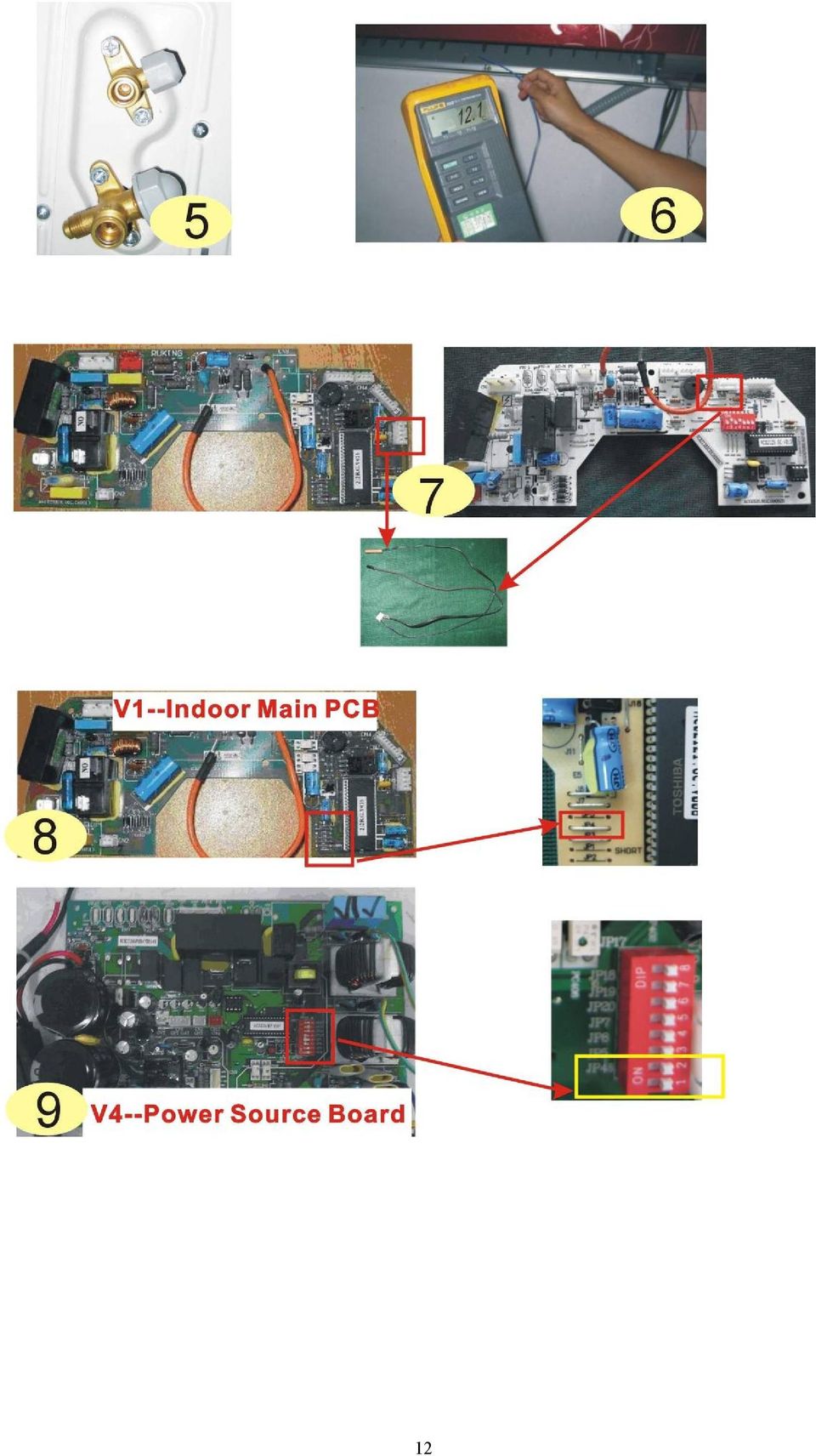
12 (4) Display E4 Symptom Display E4 System abnormal: Let the compressor run for 5 minutes. If the indoor coil temperature cannot Cause be 2 lower than that before the compressor is started (2 higher for heating mode), it can be judged that the system is abnormal. S/N Inspections How to Solve Remarks Check the high-pressure and low-pressure valves. Check the system refrigerant (Start and run under cooling mode. When the compressor is started, check the outlet temperature for its change. If the change is not obvious after 5 minutes) Check the evaporator coil temperature sensor (25 /5KΩ). For other resistance, please refer to the Temperature Resistance Sheet. 4 The above inspections are normal If not open, open again to ensure the system circulation is smooth. The system is in shortage of refrigerant. Test with pressure gauge, check the leakage point and recharge the refrigerant. Replace the temperature sensor if the resistance is incurred to drift, open or short circuiting. 1. The flow might be uneven for indoor system. Short circuit JP4 jumper of the indoor control board to shield this protection function (V1 Indoor Main PCB). 2. The flow might be uneven for indoor system. Dial the JP4 switch of the outdoor power source board to position 1 to shield this protection function (V4 Power Source Board). Replace the indoor main PCB if the problem cannot be solved by using the above methods. Photo 5 Photo 6 Photo 7 Photo 8 Photo 9 11
 Check the evaporator coil temperature sensor (25 /5KΩ).")
13 12
14 (5) Display EC Symptom Display EC Cause Outdoor communication fault between power source board and intelligent power module S/N Inspections How to Solve Remarks 1 Check the contact of communication wire Yellow-line (CN5) between power source board and Insert again if loose. part intelligent power module 2 After the complete unit is energized, check the indicators on outdoor power source board and intelligent power module The indicator on power source board blinks normal (bright for 1 second and dark for 1 second), but the indicator on intelligent power module does not work normally The indicator on intelligent power module blinks normal (bright for 1 second and dark for 1 second), but the indicator on power source board does not work normally VP1 Replace the intelligent power module Replace power board the source Replace power source board If the fault remains unsolved, replace the power source board again. If the fault remains unsolved, replace the intelligent power module again. If the fault remains unsolved, replace the intelligent power module again. Red-line part Orange-line part CN5 position and marking 13
, but the indicator on intelligent power module does not work normally The indicator on intelligent power module blinks normal (bright for 1 second and dark")
15 (6) Display EP Symptom Display EP Cause Temperature switch fault ( on top of the compressor) S/N Inspections How to Solve Remarks Check the insert position CN3 of the compressor top temperature switch wires on outdoor power source Insert again if loose. Photo 10 1 board No switch on compressor top Jumper short-circuiting (This function not provided for 1 1.5P unit) The correct sequence of U. V Check the U, V and and W wiring shall be red, W wires of the white and blue. Connect again compressor. Compressor if incorrect. Photo 11 temperature. The pressure is low. Add Check the system The refrigerant to ensure the system Photo 12 pressure. temperature pressure is normal. 2 is very high, Check the outdoor accompanied ventilation and if Install to the position as required with bad there is any in the Instruction Manual and smell. obstruction that ensure the air inlet and outlet of affects the normal the outdoor unit is smooth. radiating of the air conditioner. If the fault is solved after short circuiting, replace the shell 3 temperature switch. Compressor temperature: The If the fault remains unsolved temperature is not high. Short after replacing the shell circuit CN3. temperature switch, please replace the outdoor power source board. 14

16 1 1.5P CN3 jumper. The jumper may be used as alternative if there is no compressor top switch. The correct sequence of U. V and W wiring shall be red, white and blue 15

17 (7) Display EA Symptom Display EA Cause Current sensor fault S/N Inspections How to Solve Remarks 1 Check for refrigerant leakage V1 inverter unit : Test the voltage 2 of 5# pin to 2# pin on power factor correction V2 V3 V4 V5 VP1 VP2 inverter 3 unit Find the leakage point and recharge the refrigerant If higher than 0.4V, replace the Photo 13 intelligent power module If not higher than 0.4V, replace power factor correction Replace the outdoor power source board 16

18 (8) Display EU Symptom Display EU Cause Voltage sensor fault S/N Inspections How to Solve Remarks Insert again if loose. Photo V1 inverter unit: Communication wires between outdoor power source board and intelligent power module (CN5) V2 V3 V4 V5 VP1 VP2 Inverter Unit If the fault remains unsolved after connection again, please replace the outdoor power source board. If the fault remains unsolved after replacement of outdoor power source board, please replace the intelligent power module. Replace the outdoor power source board Check CN5 insert. 17

19 (9) Display E9 (Firstly display P0 or P9, then change to E9) Symptom Display E9 (Firstly display P0 or P9, then change to E9) Cause Intelligent power module of drive and module fault S/N Inspections How to Solve Remarks If this code is displayed when the compressor is started for several seconds or even not started, If no insert wrong, replace the check the compressor connection for intelligent power module Photo 15 correctness Check if the outdoor module is tightly installed onto the radiating fins and Fix the screws again if loose. Photo 16 Re-energize and check the if the silicone is applied evenly 1 protection code on display. Firstly display P0 P0 appears when the air conditioner is working Check the system pressure. Check the outdoor ventilation and if there is Recharge refrigerant if the pressure is low. Discharge some refrigerant if the pressure is too high. Install to the position as required in any obstruction that the Instruction Manual and ensure affects the normal the air inlet and outlet of the outdoor radiating of the air unit is smooth. conditioner. The above inspections are normal, but the fault remains unsolved If this code is displayed when the compressor is started for several seconds or even not started, check the compressor connection for correctness Replace the intelligent power module If no insert wrong, replace the intelligent power module Re-energize Cooling / heating is Replace the intelligent power and check the P9 appears after normal during run module 2 protection code on display. Firstly display P9 the air conditioner is started and has run for a period of time If the cooling / heating is abnormal, check the compressor wiring for correctness. Insert again if loose. Be sure to apply silicone when replacing intelligent power module. When the compressor is restarted immediately after stop, this might also cause P9 protection because the cooling system is not stable. Try starting the air conditioner again after a longer period of stop 18

20 The wires on U, V and W ends are respectively colored red, white and blue. Apply the silicone evenly. If the screw is not fixed tightly to position, it is easy to cause poor radiation and damage to the elements. 19

21 (10) Display E0 E5 Symptom Display E0 E5 Cause Indoor / outdoor communication fault S/N Inspections How to Solve Remarks 1. Check if the indoor and outdoor connections are correct. The terminal L and N shall correspond to each other on indoor and outdoor units. Measure the voltage on outdoor terminal L and N (before display of E0 fault). If the voltage Replace the indoor control board. Photo 17 (red) is 0 : 2. If the L & N voltage is normal, measure the voltage between the outdoor terminal N and 1. If the voltage Replace the indoor main PCB. change occurs between 0~24V (change pulse voltage) 3. If the L & N voltage is normal, measure the voltage between the outdoor terminal N and 1. If the voltage Replace the outdoor power source Photo 17 (yellow) Energize change occurs between 0~12V( change pulse voltage), but board and there is no 24V: observe for approx If the L & N voltage is normal, measure the voltage between the outdoor terminal N and 1. If the voltage has no change: Firstly replace the indoor main PCB. If the fault remains unsolved, replace the outdoor power source board. 1 minutes. If E0 is always displayed or changed to E5 after a period of time: 5. Indicator on outdoor power source board 1) The indicator is dark: Check PFC board Test the pins of rectifier bridge, fast recovery diode (FRD) and IGBT elements for any breakdown, short circuiting or damage. 2) If no damage, test the DC voltage between DC+ and DC-. If the voltage is approx. 300V: 3) If no damage, test the DC voltage between DC+ and DC-. If the voltage is zero: If damaged, it is needed to replace PFC board. Replace the power source board. Replace the power factor correction. Photo 17 (red) Photo 18 (yellow) Firstly replace the intelligent power 6. If the problem cannot be solved by using the methods above: module. If the problem remains unsolved, replace the indoor main PCB. Power source board. power factor correction. 7. If this fault appears at the initial installation and testing of the complete unit, please check if the Replace with the same generation indoor control board and outdoor inverter module of products are of the same generation. 20
22 Test the DC voltage between DC+ and DC-. Check power factor correction Test the pins of rectifier bridge, fast recovery diode (FRD) and IGBT elements for any breakdown, short circuiting or damage. 21
23 (11) Display EE Symptom Display EE Cause EEPROM fault S/N Inspections How to Solve Remarks Shut down the power supply and re-energize. If the fault remains, it is needed to check if the indoor Fix again Photo 19 EEPROM installation is loose or 1 improper. Shut down the power supply and re-energize. If the fault remains, it is needed to check if the outdoor Fix again Photo 20 EEPROM installation is loose or improper. 2 If the installation is good: Replace the indoor main PCB firstly 3 If the fault remains unsolved after replacement of the indoor control board: Outdoor power source board EEPROM installation is improper EEPROM installation is improper 22
24 (12) Display P0 Re-energize and check the protection code on display. Firstly display P0 Symptom Display P0 Cause Variable-frequency drive Inspections How to Solve Remarks If this code is displayed when the compressor is started for several seconds or even not started, check the compressor connection for correctness. P0 appears when the air conditioner is working Check if the outdoor intelligent power module is tightly installed onto the radiating fins and if the silicone is applied evenly. Check the system pressure. Check the outdoor ventilation and if there is any obstruction that affects the normal radiating of the air conditioner. The above inspections are normal, but the fault remains unsolved If no insert wrong, replace the intelligent power module Photo 22 Fix the radiator again if loose. Photo 23 Recharge refrigerant if the pressure is low. Discharge some refrigerant if the pressure is too high. Install to the position as required in the Instruction Manual and ensure the air inlet and outlet of the outdoor unit is smooth. Replace the intelligent power module The wires on U, V and W ends are respectively colored red, white and blue. If the screw is not fixed tightly to position, it is easy to cause poor radiation and damage to the elements. 23
25 (13) Display P1 Symptom Display P1 Cause Overvoltage / undervoltage protection S/N Inspections How to Solve Remarks 1 Test the supply voltage if it is between 160V ~260V(AC). It is normal protection if exceeding this range. Test if the voltage between L and N 2 terminal of outdoor unit is within 160V~260V(AC). 3 If the voltage is normal: It is normal protection if exceeding this range. Replace the outdoor power source board Photo 24 (14) Display P2 Symptom Display P2 Cause Overcurrent protection S/N Inspections How to Solve Remarks 1 Check if the outdoor fan motor is Replace the damaged capacitor stopped due to overheat protection, and the damaged outdoor fan or damaged, and if the fan capacitor motor. is damaged. VP1-- Replace the power source board 2 V1-- Replace the intelligent power source board or intelligent power module. power module damaged V4 and VP2-- Replace the intelligent power module. 24
26 (15) Display P4 Symptom Display P4 Cause Exhaust overtemperature protection S/N Inspections How to Solve Remarks 1 Install to the position as required in Check if the air inlet and outlet of the Instruction Manual and ensure outdoor unit is blocked by any the air inlet and outlet of the obstructions. outdoor unit is smooth. 2 Check the system for shortage of refrigerant. Add refrigerant 3 Check if the exhaust temperature sensor is drifted, short circuited or 4 open circuited. (25 /20KΩ). For other resistances, please refer to the Exhaust Temperature Sensor Resistance Sheet) Control board damaged Replace the exhaust temperature sensor Replace the outdoor power source boar Photo (16) Display P5 Symptom Display P5 Cause Subcooling protection under cooling mode S/N Inspections How to Solve Remarks 1 Install to the position as required in Check if the air inlet and outlet of the Instruction Manual and ensure indoor unit is blocked by any the air inlet and outlet of the obstructions. outdoor unit is smooth. 2 Check the system for shortage of refrigerant. Add refrigerant 3 Check if the exhaust temperature sensor is drifted, short circuited or open circuited. (Measure the resistance of the resistors on two ends of indoor temperature sensor: (25 / 5KΩ). For other resistances, please refer to the Temperature Resistance Sheet (Appendix 1). Replace room temperature sensor (IRT) and Indoor pipe (coil) temperature sensor (IPT) 4 Control board damaged Replace the indoor control board Photo 25 25
27 25 (17) Display P6 Symptom Display P6 Cause Overheating protection under cooling mode S/N Inspections How to Solve Remarks 1 Check if the air inlet and outlet of Install to the position as required in outdoor unit is blocked by any the Instruction Manual and ensure obstructions. the air inlet and outlet of the outdoor unit is smooth. 2 Check the system for shortage of Add refrigerant refrigerant. 3 Check if the outdoor evaporator coil Replace the outdoor coil Photo 26 temperature sensor is drifted, short temperature sensor circuited or open circuited (25 /5KΩ). For other resistance, please refer to the Temperature Resistance Sheet. 4 Control board damaged Replace the outdoor power source board 26 26
28 (18) Display P7 Symptom Display P7 Cause Overheating protection under heating mode S/N Inspections How to Solve Remarks Check if the air inlet and outlet of Install to the position as required in 1 outdoor unit is blocked by any the Instruction Manual and ensure obstructions. the air inlet and outlet of the outdoor unit is smooth. 2 Check the system for shortage of refrigerant. Add refrigerant Check if the exhaust temperature sensor is drifted, short circuited or open 3 circuited. (Measure the resistance of Replace the Room temperature the resistors on two ends of indoor sensor(irt) and Indoor pipe(coil) temperature sensor: (25 / 5KΩ). For temperature sensor(ipt) other resistances, please refer to the Photo 27 Temperature Resistance Sheet (Appendix 1). 4 Control board damaged Replace the indoor control board 27 (19) Display P8 Symptom Display P8 Cause Outdoor overtemperature / undertemperature protection S/N Inspections How to Solve Remarks The compressor cannot run under cooling mode when the outdoor 1 temperature is lower than -1, or run under heating mode when the outdoor Normal protection function temperature is higher than 33, whilst the compressor alarms P8 protection. 2 If the temperature is not within the protective range above, please refer to the Temperature Resistance Sheet (See Appendix). Use the multimeter to measure the resistors on the two ends Replace the sensor if it is incurred to drift, open circuiting or short Photo 28 of outdoor intake temperature sensor circuiting. (CN1) (25 /5KΩ). For other resistance, please refer to the Temperature Resistance Sheet. 3 If the fault remains unsolved after replacement of the sensor Replace the outdoor power source board 27
29 28 (20) Display P9 Symptom Display E9 (Firstly display P0 or P9, then change to E9) Cause Intelligent power module of drive and module fault S/N Inspections How to Solve Remarks If this code is displayed when the compressor is started for several If no insert wrong, seconds or even not started, check replace the intelligent Photo 29 the compressor connection for power module. correctness. P9 appears Replace the intelligent Re-energize after the power module.(be sure to and check Cooling/heating is air apply silicone when Photo 30 the normal during run conditioner replacing the intelligent protection 1 is started power module.). code display. Firstly display P9 on and has run for a period of time If the cooling / heating are abnormal, check the compressor wiring for correctness. When the compressor is restarted immediately after stop, this might also cause P9 protection because the cooling system is not stable. Insert again if loose Try starting the air conditioner again after a longer period of stop 28
30 The wires on U, V and W ends are respectively colored red, white and blue. 2. Other faults 1) The indoor unit works normally but the outdoor unit does not work. Cause Analysis: a) If fault code is displayed: If yes, treat according to fault code. If no, check according to the following steps. b) If the outdoor fan runs normally (The outdoor fan is started 5 seconds before the compressor is started, and it is stopped 15 seconds after the compressor is stopped), the client might make wrong judgment on that the outdoor unit does not work because the compressor working frequency is low or the system is in shortage of refrigerant. Check the system cooling / heating effect and confirm if the system is in shortage of refrigerant. c) Check if the resistance of each temperature sensor is drifted (See appendix for the temperature sensor parameters): If yes, replace the temperature sensor. d) Check if the JP3 jumper of indoor control board is soldered. If not, solder the jumper. Then restart the unit and check what protection code will be displayed. Treat according to the fault code. e) Check if the indoor / outdoor and circuit board wiring. Check if the connection is secure. Please tighten the wires. 2) The outdoor unit is stopped when the air conditioner has run for a period of time Cause Analysis: a) If any fault is displayed after stop: If yes, treat according to fault code. If not, check according to Step (b). b) Check if the supply voltage is normal, including the voltage change when the air condition is 29
31 started. If the voltage is unstable or changes too heavily, please check the power source. If no problem, check according to Step (c). c) Check if the temperature sensors are normal (See appendix for the temperature sensor parameters). Check if the resistance is drifted, open circuited or short circuited. If yes, replace the sensor. If normal, check according to Step (d). d) Check if the indoor / outdoor circuit connection and power connection are in good contact. If no, tighten the connection wires. If yes, check according to Step (e). e) Check if the JP3 jumper of indoor control board is soldered. If not, solder the jumper. Then restart the unit and check what protection code will be displayed. Treat according to the fault code. f) Check if the refrigerant is too much or too less. If yes, add refrigerant. 3) The air conditioner is tripped when it is started. Cause Analysis: a) Check if the user's power source plug is correctly connected (for example, the ground wire might be wrongly connected as the neutral wire) b) Check if the indoor / outdoor circuit and the wiring terminal are correctly connected, and if there is short circuiting. c) Check if the outdoor circuit board, wiring terminal and power connection wires are damaged, and if there is short circuiting to the metal parts. d) Check if the rectifier bridge of outdoor controller (See appendix for its bridge) is short circuited (The short circuiting of rectifier bridge will probably cause tripping error). 4) The complete unit does not work Cause Analysis: a) If fault code is displayed: If yes, treat according to fault code. If no, check according to Step (2). b) Check if the power plug is electrified. If no, check the power source. If yes, check if the controller fuse is good.. If no, replace the fuse. If yes, check according to Step (3). c) Check if the resistance of the sensors on indoor and outdoor units is drifted. If yes, replace the sensor. If no, check according to Step (4). d) Check if the indoor and outdoor communication is failed. The step is same as that for check when the indoor unit works normally but the outdoor unit does not work. 30
32 Appendix 1 1. Indoor main PCB: Jumper for Function Selection No power relay, with duplicate insert as replacement Jumper for Function Selection Electric heater control relay 31
33 Indoor board for BL floor-standing inverter unit (display board + power drive board) 2. Outdoor power source board V5 32
34 3. Power factor correction 4. Intelligent power module: 33
35 34
36 35
37 Appendix 3 Silk-printed label on outdoor control board of inverter unit Control board connection Connector label Description label Relay label Remarks AC power incoming wire L P1 AC-L AC power incoming wire N P2 AC-N It is required to reserve 4 inserts at least To indoor communication wire P3 S Ground wire P0 GND Outgoing wire L after filter P4 L K1 Relay control Outgoing wire N after filter P5 N For multiple wires, use P5-1 and P5-2 to identify. DC+ input P6-1 DC+ DC- input P7-1 DC- DC+ output P6-2 DC+ DC- output P7-2 DC- 4-way valve output P8 VAL K4 Outdoor fan HI output P9-1 H K2 Outdoor fan LOW output P9-2 L K3 Outdoor fan capacitor P9-3 C Compressor output phase-u P10-1 U Compressor output phase-v P10-2 V Compressor output phase-w P10-3 W Module DC+ input P6B DC+ Intelligent power module Module DC- input P7B DC- Intelligent power module PFC board rectified input + (Direct-insert bridge AC input) PFC board rectified input - (Direct-insert bridge AC input) P11 DC+ Power factor correction P12 DC- Power factor correction PFC inductance interface P13 P14 L Power factor correction PFC DC+ output P6C DC+ Power factor correction PFC DC- output P7C DC- Power factor correction Outdoor fan DC motor socket CN9 Outdoor temperature sensor CN1 Exhaust pipe temperature sensor CN2 Suction pipe temperature sensor CN10 Compressor top thermostat CN3 36
38 Switching power output of power source board Communication signal of power source board and module board Electronic expansion valve control signal Electronic expansion valve socket Communication between power source board and PFC board Communication between nodule board and PFC board Base Auxiliary heating CN4 CN5 CN6 CN7 CN4B on Intelligent power module, and CN4C on Power factor correction CN5B on Intelligent power module CN6B on Intelligent power module CN9 CN9C on Power factor correction CN8B(Module board) CN11 CN8B on Power factor correction Cautions on Replacement of PCB Boards 1, Directive for Replacement of Inverter Module When replacing Mitsubishi inverter module, the technician must take care on the operating process for replacement of inverter module. Special care shall be taken to ensure the coating quality of thermal grease. The detailed directive is as follows: 1. Before replacing the inverter module, make sure to eliminate the old thermal grease and foreign particles with soft clean cloth before you can apply the new thermal grease. Always use the thermal grease provided by the customer service department or the same silicone grease as used in the factory. Never use any other product of poor quality. Operate in strict accordance with the guideline. 2. Ensure that the thermal grease (silicone grease) is applied thin, flat and even. Use plastic scraper to apply the grease. Firstly, place a tiny quantity of thermal grease at the center of the place where the grease is to be coated. Then, use the plastic scraper to apply the grease at the center slightly and evenly onto the entire surface to be treated. In consideration of the deviation in the levelness of radiating fin, the thickness of thermal grease must be 0.1mm (for small area) to 0.3mm (for large area), depending on the size of radiating area. Note: The function of thermal grease is to fill up the gap and let the surface tightly adhered. It is not true the more the better". 3. Before placing the greased module flatly onto the radiating fin to tighten the screws, firstly hold down with the hands; then press and move back and forth slightly until it is in full contact before tightening the screws. When tightening the screws, take special care on the strength of radiator materials when using the electric screwdriver, torque screwdriver or torque wrench. Ensure that the screws are correctly tightened to position. The tightening force varies with the module. 4. Cautions on installation of screws on inverter module: If the tightening force is applied extremely unbalance`d during installation of the module onto the radiator, the silicon chip inside the module may be deformed due to the stress. And this might cause damage or degrade to the module. Therefore, be sure to operate according to the required tightening sequence. The recommended tightening sequence for the inverter module fixed by two screws is as shown 37
39 below: A\ Pre-tightening 1 2 B\ Final tightening 1 2 Figure Recommended Tightening Sequence for Screws Other cautions: As the module is a precious and expensive element, never keep the new module close to magnetic object or touch the module with electrostatic object (including direct touch with your finger). Especially, touch with the port of signal terminal is easy to cause module internal breakdown and results in failure to use. If possible, you may wear electrostatic ring or glove. 2. Directive for Replacement of Power factor correction 1) Insulation paper must be attached between power diode, IGBT, rectifier and radiating fins. The screw locking torque is 7±0.5kgf.cm. Do not loosen the insulation paper after attaching it fully flat onto the radiator. To retighten after loosening, it is needed to eliminate the aluminum scraps on the radiator before retightening. Insulation paper 2) It is also needed apply the thermal grease evenly when replacing and installing the PFC with radiating substrate. 3. Directive for Replacement of Outdoor Power Source Board 1) The outdoor control is mostly the components carrying high current. The controller is designed of partial isolation and many circuits are commonly grounded with the high current. Take care on human safety. 38
40 2) As the high-current circuit is close to the light-current circuit, take care on the measuring position and safety problems during repair. 3) As there is large electrolytic capacitor on the outdoor power source board, plentiful residual electrons shall be discharged for a period of time after the power supply is cut off. In this case, please wait patiently until the capacitor is fully discharged before proceeding to further operation. Full discharge may take approx. 30 seconds. You may also connect a load (e.g. electric iron) between DC- and DC+ for manual discharge. After thorough discharge, use the multimeter RX10K to measure. The pointer shall point to 0 position and then slowly return to. If not, the electrolytic capacitor is damaged. 4) Make sure to have some understanding to the circuit before carrying out repair. Most fundamentally, the operator must know the composition of the circuits, position of each part and the possible function. 5) It is an extremely unscientific repair method for starting the measurement immediately after getting the circuit board, or directly energizing it to start the test. This will probably cause secondary damage to the repair board. 6) The indoor and outdoor wires must be kept in correct order. If not, it might cause failure and damage to the electric controller. When removing the screws, take protective measures to prevent the screws or other objects from falling down onto the circuit board or into the electric control box. If any, be sure to eliminate them on time. 39
Repair Guideline for SANYO New Erp. DC Inverter Air Conditioner (Published in May, 2013)
") Repair Guideline for SANYO New Erp DC Inverter Air Conditioner (Published in May, 2013) Contents I. Electronic Control of DC Inverter Air Conditioner 2 1. Main parts of the electronic control of DC inverter
Repair Guideline for SANYO New Erp DC Inverter Air Conditioner (Published in May, 2013) Contents I. Electronic Control of DC Inverter Air Conditioner 2 1. Main parts of the electronic control of DC inverter
Repair Guideline for TCL DC Inverter Air Conditioner
 Repair Guideline for TCL DC Inverter Air Conditioner FLOS SERIE---V3 0 CONTENTS Ⅰ. Introduction of New control board for outdoor unit...2 1. The structure of control board... 2 2. Diagram of outdoor unit........4
Failure code manual. content
 Failure code manual content 一 wall split AC series 2 二 floor standing AC series. 4 三 portable AC series.. 5 四 dehumidifer 6 五 DC inverter single split series...7 六 DC inverter multi-split series 10 1 一
14. Troubleshooting Guide
 14. Guide 14.1 Refrigeration Cycle System In order to diagnose malfunctions, ensure the air conditioner is free from electrical problems before inspecting the refrigeration cycle. Such problems include
Indoor coil is too warm in cooling mode or too cold in heating mode. Reversing valve or coil thermistor is faulty
 Codes Room Air Conditioner range: Indoor unit alarm s If timer lamp flashes for 1 second on, 1 second off, this indicates pre heating on the coil during heating mode and is not an error. If timer lamp
SERVICE INSTRUCTION R410A. WALL MOUNTEDtype INVERTER SPLIT TYPE ROOM AIR CONDITIONER. Models Indoor unit Outdoor unit
 SERVICE INSTRUCTION SPLIT TYPE ROOM AIR CONDITIONER WALL MOUNTEDtype INVERTER Models Indoor unit Outdoor unit ASYG07LECA ASYG09LECA ASYG12LECA ASYG14LECA AOYG07LEC AOYG09LEC AOYG12LEC AOYG14LEC R410A CONTENTS
SERVICE MANUAL. Room Air Conditioner Multi Split type Outdoor unit /R410A DC Inverter/
 SERVICE MANUAL Room Air Conditioner Multi Split type Outdoor unit /R410A DC Inverter/ FS2MI-147HFD FS2MI-187HFD FS3MI-217HFD FS3MI-277HFD FS4MI-277HFD FS4MI-367HFD FS5MI-367HFD NOTE: Before servicing the
CONTENTS 1. IMPORTANT NOTICE 2 2. TECHNICAL SPECIFICATION 3 3. OPERATION DETAILS 4 4. WIRING DIAGRAM 11 5. EXPLOSION VIEW 12 6.
 TCL WALL MOUNTED SPLIT-TYPE AIR CONDITIONERS SERVICE MANUAL No.TE051220 Models TAC-09CHSA/GI TAC-12CHSA/GI CONTENTS 1. IMPORTANT NOTICE 2 2. TECHNICAL SPECIFICATION 3 3. OPERATION DETAILS 4 4. WIRING DIAGRAM
Technical service manual 2009
 MULTI SPLIT TYPE, HEAT PUMP AIR CONDITIONERS Technical service manual 2009 KSIM MULTI ZONE SERIES R410A DC Inverter multi Series Models KSIM20912-H216 KSIM30912-H216 KSIM40912-H216 CONTENT 1. Product features
Si10-417_C. Pocket Manual. Service Diagnosis SPLIT & MULTI
 Pocket Manual Service Diagnosis SPLIT & MULTI Service Diagnosis SPLIT & MULTI 1. Troubleshooting with LED...5 1.1 Indoor Unit... 5 1.2 Outdoor Unit... 10 2. Troubleshooting by Symptoms...11 2.1 Air conditioner
SERVICE INSTRUCTION R410A. WALL MOUNTEDtype SPLIT TYPE ROOM AIR CONDITIONER INVERTER. Models Indoor unit Outdoor unit AOU 9RLFW AOU12RLFW AOU15RLS
 SERVICE INSTRUCTION SPLIT TYPE ROOM AIR CONDITIONER WALL MOUNTEDtype INVERTER Models Indoor unit Outdoor unit ASU 9RLF ASURLF ASU5RLS AOU 9RLFW AOURLFW AOU5RLS R40A CONTENTS. DESCRIPTION OF EACH CONTROL
LG Air Conditioning Multi F(DX) Fault Codes Sheet. Multi Split Units
 Fault Codes Sheet. Multi Split Units") Multi Split Units If there is a fault on any LG Multi unit, an Error mark is indicated on the display window of the indoor unit, wired-remote controller, and LED s of outdoor unit control board. A two
Multi Split Units If there is a fault on any LG Multi unit, an Error mark is indicated on the display window of the indoor unit, wired-remote controller, and LED s of outdoor unit control board. A two
Service manual. Website: www.andico.com.au CAUTION - BEFORE SERVICING THE UNIT, READ THE SAFETY - PRECAUTIONS IN THIS MANUAL.
 Website: www.andico.com.au Service manual CAUTION - BEFORE SERVICING THE UNIT, READ THE SAFETY - PRECAUTIONS IN THIS MANUAL. - ONLY FOR AUTHORISED SERVICE PERSONNEL. MODELS: MPK1-09CR-QB8 MPK1-12ER-QB6
LG Air Conditioning - Universal Split Fault Codes Sheet. Universal Split Systems
 Universal Split Systems If there is a fault on any LG Universal unit, a two digit number will appear on the remote controllers led display. If the unit does not have a remote controller the fault will
13. Troubleshooting. Indoor unit s LED indication of Corona DC inverter unit. Indoor unit s LED indication of Alfa DC inverter unit
 Troubleshooting 13. Troubleshooting Indoor unit s LED indication of Corona DC inverter unit MCAC-HTSM-2007-11 E0 E1 E2 E3 E5 E6 P0 P1 P2 P3 P5 EEPROM error outdoor communication error Zero-crossing examination
Midea Commercial Air Conditioner Malfunction Handbook
 Midea Commercial Air Conditioner Malfunction Handbook May 1, 2008 Customer Service Philosophy of Midea Air Conditioner Service Target: 100% Customer Satisfaction Service Standard: 100% Earnestness Service
Technical service manual
 GD Midea Refrigeration Equipment Co.,Ltd ODMI-A-1202 MULTI SPLIT TYPE, HEAT PUMP AIR CONDITIONERS Technical service manual R410A Multi DC inverter 220~240V-1Ph-50Hz Outdoor units Models M2OC-14HRDN1 M2OC-14HRDN1-Q
Haier Air conditioner
 For Europe Haier Air conditioner HAND in HAND HIGHER and HIGHER Page:1 For Europe HSU-09/12HVA103/R2(DB) HSU-09/12RHA103/R2(DB) Page:2 Error Codes and Description indoor and outdoor display(1) indoor Code
Air Conditioner Water Heater - A Product of HotSpot Energy LLC
 Air Conditioner Water Heater - A Product of HotSpot Energy LLC PLEASE READ THIS BEFORE YOU INSTALL THE UNIT 1. This air conditioner must be installed and/or repaired by a qualified technician. If you perform
543-0032-00, 943-0032-00. User s Manual
 543-0032-00, 943-0032-00 User s Manual 1 Comfort Alert Diagnostics Faster Service And Improved Accuracy The Comfort Alert diagnostics module is a breakthrough innovation for troubleshooting heat pump and
INSTALLATION MANUAL. Address card EKAC10B
 INSTALLATION MANUAL 88 44 µchiller compact 70 64 4a 4b G G0 power supply G G0 power supply 50 5 50 5 4a 4b 5a 5b 4 5a 5b Installation manual READ THIS MANUAL ATTENTIVELY BEFORE STARTING UP THE UNIT. DO
R22. K Control. Indoor Unit. Nomenclature. Compatibility PL H 3 G K H B. Unit style Heat Pump Horse Power
 R22. K Control. Indoor Unit. Nomenclature. PL H 3 G K H B Compatibility Unit style Heat Pump Horse Power Control Boost Heaters R22. K Control. Outdoor Unit. Nomenclature. PU H 3 Y K A Compatibility Outdoor
TECHNICAL DATA & SERVICE MANUAL SPLIT SYSTEM AIR CONDITIONER INDOOR UNIT: AW52AL AW64AL AW52AL 387030095 AW64AL 0.8180.463.0 07/05
 TECHNICAL DATA & SERVICE MANUAL INDOOR UNIT: AW52AL AW64AL SPLIT SYSTEM AIR CONDITIONER Model No. Product Code No. AW52AL 387030095 AW64AL 387030096 0.8180.463.0 07/05 IMPORTANT! Please read before installation
SERVICE MANUAL SPLIT SYSTEM ROOM AIR CONDITIONER SHARP CORPORATION SHARP CORPORATION CONTENTS
 SERVICE MANUAL SPLIT SYSTEM ROOM AIR CONDITIONER INDOOR UNIT AH-129 AH-MP14 OUTDOOR UNIT AU-129 AU-MP14 CONTENTS SPECIFICATIONS...2 EXTERNAL DIMENSIONS...4 WIRING DIAGRAMS...5 ELECTRICAL PARTS...6 MICROCOMPUTER
Service manual. The voltage in P3 and P4 in outdoor PCB is high voltage about 310V The voltage in P5 and P6 in outdoor PCB is high voltage about 310V
 Resistance The voltage in P3 and P4 in outdoor PCB is high voltage about 310V The voltage in P5 and P6 in outdoor PCB is high voltage about 310V 9.2 Troubleshooting for indoor unit E0 E1 E2 E3 E5 E6 P0
SERVICE MANUAL. Room Air Conditioner Multi Split Wall-Mounted Type Indoor. FSAI-Pro-91AE2 FSAI-Pro-121AE2 FSAIF-Pro-181AE2
 SERVICE MANUAL Room Air Conditioner Multi Split Wall-Mounted Type Indoor FSAI-Pro-91AE2 FSAI-Pro-121AE2 FSAIF-Pro-181AE2 NOTE: Before servicing the unit, please read this at first. Always contact with
HVAC SYSTEM (AUTO A/C) (DIAGNOSTICS) AC
 (DIAGNOSTICS) AC") HVAC SYSTEM (AUTO A/C) (DIAGNOSTICS) AC Page. Basic Diagnostic Procedure.... General Description...3 3. Electrical Components Location...6 4. A/C Control Module I/O Signal...8 5. Self-diagnosis...0 6.
HVAC SYSTEM (AUTO A/C) (DIAGNOSTICS) AC Page. Basic Diagnostic Procedure.... General Description...3 3. Electrical Components Location...6 4. A/C Control Module I/O Signal...8 5. Self-diagnosis...0 6.
PANASONIC TROUBLE SHOOTING GUIDE
 A General Guide To Room Style Products Pipework Pipe sizes and lengths should be as the relevant Technical Guide Both lines should be insulated No line accessories or oil traps should be fitted In cooling
Split Air Conditioner
 Split nditioner plit itsplit ir onditioner Split Split Split Split Split User s WNER'S 'S ER'S For s: AWI/AWO-21HPR1 Delta AWI/AWO-25HPR1 Delta AWI/AWO-32HPR1 Delta AWI/AWO-53HPR1 Delta AWI/AWO-65HPR1
Oil and Coolant Circulating Heating System. Model - OCSM
 Oil and Coolant Circulating Heating System Model - OCSM Installation & Operation Manual 216280-000 REV 2 Identifying Your System The HOTSTART heating system is designed to heat fluids for use in marine
10.1 Indoor Unit Error Display
 10.1 Indoor Unit Error Display Display E0 E1 E2 E3 E5 E6 P0 P1 P2 P4 LED STATUS EEPROM parameter error Indoor / outdoor units communication protection Zero-crossing signal error Fan speed out of control
Split and Multi Split air conditioners Service information
 Split and Multi Split air conditioners Service information Programming LG wired controllers 2 New type 2 Old type 7 Fault codes 9 Wall units (single split) 9 Universal split and multi split 10 Detailed
HEATER, AIR CONDITIONING AND VENTILATION
 55-1 GROUP 55 HEATER, AIR CONDITIONING AND VENTILATION CONTENTS GENERAL DESCRIPTION 55-2 HEATER AND AIR CONDITIONING SYSTEM 55-4 HEATER CONTROL 55-6 A/C-ECU 55-7 A/C COMPRESSOR 55-9 CONDENSER 55-9 DUCT
Simple Self-Diagnosis by Malfunction Code
 Simple Self-Diagnosis by Code After Sales Service Division (SM-TS2) Detail Division 0 Indoor Unit System Others A C E F H J L P U M 7 8 9 External device activated (unified) Protection devices activated
Section 7. Evaporator thermistor. Under-and-over pressure safety switches. Connections to the ECU
 Automatic Temperature Control Diagnosis and Repair Diagnosis of Automatic A/C Systems The most common automatic A/C system malfunctions tend to be the result of basic air conditioning problems. These problems
800-292-3279 916 638-0828
 800-292-3279 916 638-0828 http://easycleansystems.com/heaters/heater-parts.html VAL6 KBE5S and KBE5L Service manual KBE5S 1 2 Specifications Type VAL6 KBE5S Heat Output 111,000BTU/h Fuel Kerosene, Diesel
Thermo Top - Troubleshooting Tree
 Thermo Top - Troubleshooting Tree 07-15-2002 CAUTION Troubleshooting requires comprehensive knowledge about the structure and theory of operation of the Thermo Top heater. Troubleshooting and repairs may
SERVICE MANUAL AE-X2M14LR MULITI SPLIT TYPE ROOM AIR CONDITIONERS (OUTDOOR UNIT) MODEL. No. S2038AEX2MLRT CONTENTS AEX2M14LR
 MODEL. No. S2038AEX2MLRT CONTENTS AEX2M14LR") TopPage AEX2M14LR SERVICE MANUAL. S2038AEX2MLRT MULITI SPLIT TYPE ROOM AIR CONDITIONERS (OUTDOOR UNIT) MODEL AE-X2M14LR In the interests of user-safety (Required by safety regulations in some countries)
TopPage AEX2M14LR SERVICE MANUAL. S2038AEX2MLRT MULITI SPLIT TYPE ROOM AIR CONDITIONERS (OUTDOOR UNIT) MODEL AE-X2M14LR In the interests of user-safety (Required by safety regulations in some countries)
1 4. 3 4-2 ABNORMAL OPERATION. 4-2-1 Error code Display. Specifics Error Code. Subsection Error Code. Subsection and Specifics Error code target
 4-2 ABNORMAL OPERATI 4-2-1 An is represented by 3 digit characters. The first 2 digit means the subsection, and the last 1 digit means the specifics. Ex.) Indoor unit Network communication Error Subsection
SERVICE MANUAL OUTDOOR UNIT. No. OBH590 REVISED EDITION-B. Models HFC
 SPLIT-TYPE AIR CONDITIONERS Revision B: MUZ-EF25/35/42/50VE - E2 and MUZ-EF25/35VEH - E2 have been added. Please void OBH590 REVISED EDITION-A. OUTDOOR UNIT SERVICE MANUAL HFC utilized R410A. OBH590 REVISED
MCR1900 Media Converter 19-Slot Chassis
 MCR1900 Media Converter 19-Slot Chassis Installation Guide Part #5500304-11 Copyright Statement This document must not be reproduced in any way whatsoever, either printed or electronically, without the
FILE NO. SVM-07013 11. HOW TO DIAGNOSE THE TROUBLE
 FILE. SVM-070. HOW TO DIAGSE THE TROUBLE The pulse motor circuits are mounted to both indoor and outdoor units. Therefore, diagnose troubles according to the trouble diagnosis procedure as described below.
Service Guide 12/27/03 TESTING, SERVICE & REPAIR GUIDE (For SH Space Heating Models & RA Water Heating Models)
") TESTING, SERVICE & REPAIR GUIDE (For SH Space Heating Models & RA Water Heating Models) WARNING - HIGH VOLTAGE AC electrical circuits are connected to this heater. Do not attempt any service work on the
TESTING, SERVICE & REPAIR GUIDE (For SH Space Heating Models & RA Water Heating Models) WARNING - HIGH VOLTAGE AC electrical circuits are connected to this heater. Do not attempt any service work on the
Heating, Ventilation, Air Conditioning and Refrigeration (HVACR)
") Heating, Ventilation, Air Conditioning and Refrigeration (HVACR) I. Demonstrate safety skills in typical HVACR work situations to NATE Core Installer Knowledge Areas for Technician Excellence for Safety
Heating, Ventilation, Air Conditioning and Refrigeration (HVACR) I. Demonstrate safety skills in typical HVACR work situations to NATE Core Installer Knowledge Areas for Technician Excellence for Safety
EVANS ELECTRONIC TEMPERATURE CONTROL TROUBLESHOOTING GUIDE for systems equipped with electric coolant valve and external PC board.
 EVANS ELECTRONIC TEMPERATURE CONTROL TROUBLESHOOTING GUIDE for systems equipped with electric coolant valve and external PC board. This Troubleshooting Guide covers the electric coolant valve and control
sip Sanyo Modbus Guide Technical Specification Pinouts, Cable Connections & Wiring Issue 2: February 2009 Synapsys Solutions Ltd, all rights reserved
 Sanyo Section : Section : Section : Section : Section : sip Modbus Guide Configuration Modbus Table Technical Specification Pinouts, Cable Connections & Wiring Alarm Fault Codes Issue : February 009 Section
SECTION 26 29 23 VARIABLE FREQUENCY DRIVES
 SECTION 26 29 23 VARIABLE FREQUENCY DRIVES PART 1 GENERAL 1.01 SCOPE A. Furnish and install individual freestanding variable frequency AC drives (VFD) as shown on the Drawings and specified herein. 1.02
ELECTRONIC THERMOSTAT AND THERMOMETER With SPEED CONTROL
 148 OLD CONCORD TURNPIKE, BARRINGTON NH 03825 USA TEL (603) 868-5720 FAX (603) 868-1040 1-800-435-6708 E-Mail:[email protected] www.seafrost.com ELECTRONIC THERMOSTAT AND THERMOMETER With SPEED CONTROL
WALL MOUNTED SPLIT TYPE AIR CONDITIONER
 WALL MOUNTED SPLIT TYPE AIR CONDITIONER MANUAL 8 OM-G12-ACSON CONTENTS - Operating Guide page 1 - G12 Remote Controller Indication page 2 - Indicator Lights page 4 - Installation of Aroma page 5 - Auto
SERVICE INSTRUCTION R410A. SPLIT TYPE ROOM AIR CONDITIONER Universal Floor / Ceiling Duct / Cassette Wall Mounted / Floor type INVERTER MULTI
 SERVICE INSTRUCTION SPLIT TYPE ROOM AIR CONDITIONER Universal Floor / Ceiling Duct / Cassette Wall Mounted / Floor type INVERTER MULTI R410A Models Indoor unit Outdoor unit AB*14LBAJ AB*18LBAJ AB*F14LAT
HERZ-Thermal Actuators
 HERZ-Thermal Actuators Data Sheet 7708-7990, Issue 1011 Dimensions in mm 1 7710 00 1 7710 01 1 7711 18 1 7710 80 1 7710 81 1 7711 80 1 7711 81 1 7990 00 1 7980 00 1 7708 11 1 7708 10 1 7708 23 1 7709 01
NewAir AC-10000E, AC-10000H Portable Air Conditioner Owner s Manual PLEASE READ AND SAVE THESE INSTRUCTIONS
 NewAir AC-10000E, AC-10000H Portable Air Conditioner Owner s Manual PLEASE READ AND SAVE THESE INSTRUCTIONS BEFORE USE GENERAL SAFETY INSTRUCTIONS: ALWAYS OPERATE THE UNIT IN AN UPRIGHT POSITION AND PLACE
SERVICE MANUAL FOR 6535 SERIES TWO TON HIGH EFFICIENCY PACKAGED HEAT PUMPS
 SERVICE MANUAL FOR 6535 SERIES TWO TON HIGH EFFICIENCY PACKAGED HEAT PUMPS TABLE OF CONTENTS 1. Warnings...2 2. Accessibility Of Appliance...3 3. Unit Dimensions And Specifications...3 4. Unit Specifications
Use and Care Manual. Model CPA12KH AIR CONDITIONER
 Use and Care Manual Model CPA12KH AIR CONDITIONER Introduction Thank you for choosing this air conditioner to provide you and your family with all of the "Home Comfort" requirements for your home, cottage
Online UPS. PowerWalker VFI 1000R/1U
 Online UPS PowerWalker VFI 1000R/1U Manual Uninterruptible Power Supply System Table of Contents 1. Important Safety Warning... 1 1-1. Transportation... 1 1-2. Preparation... 1 1-3. Installation... 1 1-4.
Portable Air Conditioner
 Portable Air Conditioner Owner's Manual Model:3 in 1 12,000 Btu/h Series 3 Please read this owner s manual carefully before operation and retain it for future reference. CONTENTS 1. SUMMARY...1 2. PORTABLE
Heater and Air Conditioner, Blend Air System, Troubleshooting 83.06
 A/C Performance Diagnosis Problem Warm Airflow When the Air Conditioner is On, A/C Not Working, or Poor A/C Performance (dash outlet temperature is too high) Problem Warm Airflow When the Air Conditioner
TECHNICAL & SERVICE MANUAL WINDOW TYPE AIR CONDITIONER SA 79G SA 99G FILE NO. SA 79G SA 99G REFERENCE NO. SM700402
 TECHNICAL & SERVICE MANUAL SA 79G SA 99G FILE NO. WINDOW TYPE AIR CONDITIONER Model No. Product Code No. Destination SA-79G-A 1 851 005 18 General (50Hz) & Europe SA-99G-A 1 851 005 19 SA 79G SA 99G REFERENCE
AIR CONDITIONER INSTALLATION MANUAL
 INSTALLATION MANUAL AIR CONDITIONER Please read this installation manual completely before installing the product. Installation work must be performed in accordance with the national wiring standards by
User s Manual Before using the inverter, you need to read and save the safety instructions.
 User s Manual Before using the inverter, you need to read and save the safety instructions. STI SERIES (STI200, STI300, STI500, STI700, STI1000) Power Frequency Pure Sine Wave Inverter The information
Table Z. Troubleshooting Chart for Air Conditioners. Cause
 Troubleshooting Chart for Air Conditioners Type of Unit Complaint Cause With open-type compressor Electric motor will not start Power failure Check circuit for power source Compressor stuck Locate cause
User s Manual AURORA 1.2K/2.2K
 User s Manual AURORA 1.2K/2.2K Uninterruptible Power System Safety CAUTION This UPS utilizes voltages that may be hazardous. Do not attempt to disassemble the unit. The unit contains no user serviceable
3. SEISCO PARTS & SERVICE REMOVAL AND REPAIR GUIDE
 4 3. SEISCO PARTS & SERVICE REMOVAL AND REPAIR GUIDE A. Changing the Control Board B. Replacing a Heating Element C. Thermistor Replacement D. High Limit Switch Replacement E. Level Detector Replacement
Whale 3. User Manual and Installation Guide. DC Servo drive. Contents. 1. Safety, policy and warranty. 1.1. Safety notes. 1.2. Policy. 1.3. Warranty.
 Whale 3 DC Servo drive User Manual and Installation Guide Contents 1. Safety, policy and warranty. 1.1. Safety notes. 1.2. Policy. 1.3. Warranty. 2. Electric specifications. 2.1.Operation ranges. 3. Connections
SERVICE MANUAL MUZ-GE25VA - E1 MUZ-GE25VAH - E1 MUZ-GE35VA - E1 MUZ-GE35VAH - E1 MUZ-GE42VA - E1 MUZ-GE42VAH - E1 MUZ-GE50VA - E1 MUZ-GE50VAH - E1
 SPLIT-TYPE AIR CONDITIONERS Revision A: MUZ-GE42/50VA(H) - E1 has been added. Please void OBH516. OUTDOOR UNIT SERVICE MANUAL HFC utilized R410A. OBH516 REVISED EDITION-A Models MUZ-GE25VA - E1 MUZ-GE25VAH
TAS-18MVHN/O TAS-27MVHN/O TAS-36MVHN/O
 SERVICE MANUAL AIRCONDITIONER DC INVERTER MULTI TYPE TAS-18MVHN/O TAS-27MVHN/O TAS-36MVHN/O DC MULTI OUTDOOR UNITS CONTENTS 1. General information of Outdoor Units... 3 2. Dimensions... 4 3. Wiring Diagram...
Operational Overview and Controls Guide. Two or Three Pump IronHeart Lite with Variable Frequency Drives
 DOCUMENT: ECSEQ6-0 EFFECTIVE: 09/23/10 SUPERSEDES: Operational Overview and Controls Guide Two or Three Pump IronHeart Lite with Variable Frequency Drives 6700 Best Friend Road. Norcross, GA 30071. (770)
Subject: Circuit Board troubleshooting Bulletin
 Subject: Circuit Board troubleshooting Bulletin Problem Statement: The heater lead connections on circuit board (PN 150132) used on many 208 or 240 volt LAC, LBB, LCC, LCD, RAD, and RFD Despatch ovens
USER S MANUAL HSC-24A
 AIRREX AIR CONDITIONER USER S MANUAL HSC-24A Thank you for purchasing an AIRREX AIR CONDITIONER. BEFORE operation please read this user s manual carefully. Keep this manual readily available. It is ESSENTIAL
NewAir AC-10100E / AC-10100H Portable Air Conditioner Owner s Manual PLEASE READ AND SAVE THESE INSTRUCTIONS
 NewAir AC-10100E / AC-10100H Portable Air Conditioner Owner s Manual PLEASE READ AND SAVE THESE INSTRUCTIONS ELECTRICAL SAFETY This appliance is for indoor use only. Always turn off the unit and unplug
Specifying a Variable Frequency Drive s
 Specifying a Variable Frequency Drive s Put on by Bruce Reeves and Jeremy Gonzales Dykman Electrical Covering the Western US For all of your VFD and Soft Start and Motor Needs How To Specify a Variable
USER INSTRUCTIONS FOR GET PORTABLE 12k BTU AIR CONDITIONER MODEL No. GPACU12HR
 USER INSTRUCTIONS FOR GET PORTABLE 12k BTU AIR CONDITIONER MODEL No. GPACU12HR CONTENTS Introduction Safety Notes Identification of parts Installation instructions Operation instructions Maintenance Troubleshooting
Heat Pump Water Heater IOM Manual
 Heat Pump Water Heater IOM Manual Installation Operation & Maintenance This manual is intended as an aid to qualified service personnel for proper installation, operation and maintenance of the heat pump
Model: AC-S13CG x 2. Model No: AC-S13CGx2.doc Version 1.0
 Air Conditioner Service Manual 2 3 Model: AC-S13CG x 2 3 Content Technical specification.. 4 Performance curve.5 Outline & dimension of indoor unit..10 Outline & dimension of outdoor unit 11 Exploded view
ChapterⅠ Introduction to Products
 AI RCONDI TI ONI NG SYSTEMS Model s : UMATCH I NVERTER Ser vi cemanual Ser vi cemanual ChapterⅠ Introduction to Products 1. Kinds of Products Universal outdoor unit Duct type Floor ceiling type Cassette
CONTENTS 1. IMPORTANT NOTICE 2 2. TECHNICAL SPECIFICATION 3 3. OPERATION DETAILS 4 4. ELECTRICAL SCHEMATIC DIAGRAM 13 5. EXPLOSION VIEW 16 6
 TCL WALL MOUNTED SPLIT-TYPE AIR CONDITIONERS SERVICE MANUAL No.TE080528 Models KFTHP-12 KFTHP-18 KFTHP-24 CONTENTS 1. IMPORTANT NOTICE 2 2. TECHNICAL SPECIFICATION 3 3. OPERATION DETAILS 4 4. ELECTRICAL
Instruction Manual Model: GT-SKR010B GT-SKR015B GT-SKR020B GT-SKR030B
 Air Source Heat Pump Water Heater Domestic Series Instruction Manual Model: GT-SKR010B GT-SKR015B GT-SKR020B GT-SKR030B The instructions in this manual are for the use of qualified individuals specially
DC INVERTER SPLIT SYSTEM AIR CONDITIONER
 TECHNICAL & SERVICE MANUAL SAP-KRV9AEH + SAP-CRV9AEH SAP-KRV12AEH + SAP-CRV12AEH FILE NO. Destination: Europe DC INVERTER SPLIT SYSTEM AIR CONDITIONER Indoor Model No. SAP-KRV9AEH SAP-KRV12AEH Product
HVAC SYSTEM (HEATER, VENTILATOR, AND A/C)
") HVAC SYSTEM (HEATER, VENTILATOR, AND A/C) HEATER SYSTEM 1. Heater System A: GENERAL A semi-center type integrated air conditioning unit is used, where a high performance heater core and an evaporator core
HVAC SYSTEM (HEATER, VENTILATOR, AND A/C) HEATER SYSTEM 1. Heater System A: GENERAL A semi-center type integrated air conditioning unit is used, where a high performance heater core and an evaporator core
*.ppt 11/2/2009 12:48 PM 1
 Digital Compressor Controller *.ppt 11/2/2009 12:48 PM 1 Copeland Scroll Digital Controller Simple Controller That Enables OEM s To Use Digital Scrolls Relieves OEM From Developing Special Controllers
MODEL 2202IQ (1991-MSRP $549.00)
") F O R T H E L O V E O F M U S I C F O R T H E L O V E O F M U S I C MODEL 2202IQ (1991-MSRP $549.00) OWNER'S MANUAL AND INSTALLATION GUIDE INTRODUCTION Congratulations on your decision to purchase a LINEAR
F O R T H E L O V E O F M U S I C F O R T H E L O V E O F M U S I C MODEL 2202IQ (1991-MSRP $549.00) OWNER'S MANUAL AND INSTALLATION GUIDE INTRODUCTION Congratulations on your decision to purchase a LINEAR
AUTOMATIC CONTROL HEATING, VENTILATION AND AIR CONDITIONING SYSTEM
 SECTION 7D AUTOMATIC CONTROL HEATING, VENTILATION AND AIR CONDITIONING SYSTEM TABLE OF CONTENTS Description and Operation... 7D- General... 7D- FATC Control... 7D- FATC Input/Output Routing Diagram...
How To Use A Power Supply Unit (Upu)
") BRAVER UPS (Uninterruptible Power System) User s Manual Safety CAUTION! This UPS utilizes voltages that may be hazardous. Do not attempt to disassemble the unit. The unit contains no user replaceable parts.
BRAVER UPS (Uninterruptible Power System) User s Manual Safety CAUTION! This UPS utilizes voltages that may be hazardous. Do not attempt to disassemble the unit. The unit contains no user replaceable parts.
TIG INVERTER INSTRUCTION MANUAL
 TIG INVERTER INSTRUCTION MANUAL Contents Warning General Description Block Diagram Main Parameters Circuit Diagram Installation and Operation Caution Maintenance Spare Parts List Troubleshooting 3 4 4
MP-4000 Alarm List (Software version 2.4.3 or later)
") Service Bulletin SUBJECT: MP4000 Alarm s BULLETIN: C 100 DATE: June 19, 2013 ALARM LIST Where it is possible the alarm number is kept the same as for MP-3000. MP-3000 holds alarm number from 0 to 127.
Service Bulletin SUBJECT: MP4000 Alarm s BULLETIN: C 100 DATE: June 19, 2013 ALARM LIST Where it is possible the alarm number is kept the same as for MP-3000. MP-3000 holds alarm number from 0 to 127.
A.Y. McDonald Mfg. Co. Troubleshooting Submersible and Jet Pumps
 A.Y. McDonald Mfg. Co. Troubleshooting Submersible and Jet Pumps Troubleshooting Submersible Pumps Fuse overload or circuit breaker trips when motor is started 1. Incorrect line voltage. Check the line
NEWTECH PRO 1-2-3 KVA ONLINE UNINTERRUPTIBLE POWER SUPPLY USER MANUAL
 NEWTECH PRO 1-2-3 KVA ONLINE UNINTERRUPTIBLE POWER SUPPLY USER MANUAL [email protected] / www.tuncmatik.com Table of Contents 1. Important Safety Warning 2 1-1. Transportation 2 1-2. Preparation 2 1-3.
Programmable Thermostat MODEL 3312026.XXX With Dehumidify 3312024.XXX With Out Dehumidify
 Comfort Control Center 2 Thermostat Operating Instructions Programmable Thermostat MODEL 3312026.XXX With Dehumidify 3312024.XXX With Out Dehumidify TABLE OF CONTENTS About your new thermostat Features...2
Contractors Guide Central Inverter System Installation
 Contractors Guide Central Inverter System Installation Step By Step Procedures 2,200 Watt/VA 6 Step Installation 1. Mount Bottom Cabinet 2. Mount Top Cabinet 3. Install Batteries 4. Install Conduit 5.
..OR How To Protect your 3-Phase Equipment Investment with 3-Phase Monitors from Time Mark...
 ..OR How To Protect your 3-Phase Equipment Investment with 3-Phase Monitors from Time Mark... TIME MARK CORPORATION 11440 EAST PINE STREET TULSA, OK 74116 USA tel 918 438-1220 fax 918 437-7584 www.time-mark.com
Panasonic/Sanyo A/C Interface Modbus RTU Installation Instructions
 Panasonic/Sanyo A/C Interface Modbus RTU Installation Instructions Preface Safety warnings To avoid injury, or damage to the Modbus interface, read all installation and configuration instructions in this
OWNER S MANUAL VMH 09/12/18/27/36 InverterFlex
 OWNER S MANUAL VMH 09/12/18/27/36 InverterFlex Version C Single, Dual, Tri or Quad Zone Ductless Mini-Split System Heat Controller, Inc. 1900 Wellworth Ave. Jackson, MI 49203 (517)787-2100 www.heatcontroller.com
Air conditioning, electrical testing
 just a test. Air conditioning, electrical testing 01-253 Wire and component test using VAG1598 A test box Special tools and equipment VAG 1598 A test box and VAG 1598/11 adapter cable and VAG 1598/12 VAG1526
9ASNA-A1-1202 SERVICE MANUAL SENVILLE AIRCONDITIONER DC INVERTER SPLIT WALL-MOUNTED TYPE
 9ASNA-A1-1202 SERVICE MANUAL SENVILLE AIRCONDITIONER DC INVERTER SPLIT WALL-MOUNTED TYPE CONTENTS 1. Precaution... 1 1.1 Safety Precaution... 1 1.2 Warning... 1 2. Function... 6 3. Dimension... 9 3.1 Indoor
Technical Service Manual. Version One
 [Gree Central Air Conditioner] Technical Service Manual Ducted type unit 2.3KW-16KW Version One GREE ELECTRIC APPLIANCES.INC.OF ZHUHAI - 1 - FG Series wind pipe blowing air-conditioning unit Section One:
Installation Instructions for Alarm Module Kit A043F059
 Instruction Sheet 07-2013 Installation Instructions for Alarm Module Kit A043F059 1 Introduction The information contained within is based on information available at the time of going to print. In line
Air Conditioning Sign-Off Sheet
 Air Conditioning Sign-Off Sheet Printed Technician Name Address Social Security Number Telephone Number City State Zip Code Install Or Verify The Accuracy Of An Air Conditioner s Installation The candidate
SECTION 23 00 01 HEATING, VENTILATION AND AIR CONDITIONING EQUIPMENT
 SECTION 23 00 01 HEATING, VENTILATION AND AIR CONDITIONING EQUIPMENT PART 1 - GENERAL 1.1 DESCRIPTION A. The Work specified in this Section consists of designing, furnishing and installing factory-assembled
NO-FROST CUSTOMER SUPPORT INFORMATION INFORMATION ON THE NO-FROST TECHNOLOGY WHITE GOODS
 INFORMATION INFORMATION ON THE TECHNOLOGY The -Frost refrigerators are different from the other static refrigerators in terms of their operational system. In normal refrigerators, in the freezing section,the
Gas Oven Repair Guide
 - /6 - Gas Oven Repair Guide [ FX70*, FX50*] Ver. Aug-0 Ignition Failure Cooktop ignition Oven ignition Heating defect Oven Cooktop Abnormal Flame Button, Motors Lamp Others Smell, Smoke, Noise No Display,