Repair Guideline for TCL DC Inverter Air Conditioner
|
|
|
- Ronald Cannon
- 8 years ago
- Views:
Transcription
1 Repair Guideline for TCL DC Inverter Air Conditioner FLOS SERIE---V3 0

2 CONTENTS Ⅰ. Introduction of New control board for outdoor unit The structure of control board Diagram of outdoor unit Current flow Protection and Fault codes Ⅱ. Troubleshooting Voltage test and inspection Examples for maintenance ). Blink 10 times (E3) 9times(E7) 11times(E8) 4times 5times ). Blink 13 times(ea) 3times 13 3). Blink 37~ 48 times(e9).14 4). Blink 7 times(e0)..17 5). Blink 27 times(ee) 19 6). Blink 16 times(ef) Normally inspection Appendix 1 The PCB difference for 1HP\1.5HP\2HP \3HP. 23 Appendix 2 AD value of the sensor.. 24 Appendix 3 Silk-printed label on outdoor PCB.. 26 Appendix 4 Cautions on Replacement of PCB Boards Appendix 5 Photos of outdoor unit PCB

3 Ⅰ. Introduction of New control board for outdoor unit 1. The structure of control board. There are indoor unit PCB and outdoor unit PCB for inverter air conditioner. For the outdoor control board, main function shown as follow: the 1)1.0HP 1.5HP S.H. 2

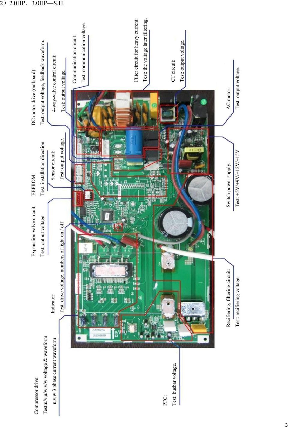
4 2)2.0HP 3.0HP S.H. 3
5 2. Diagram of outdoor unit. 1)1.0HP 1.5HP S.H. 4

6 2)2.0HP 3.0HP S.H. 5
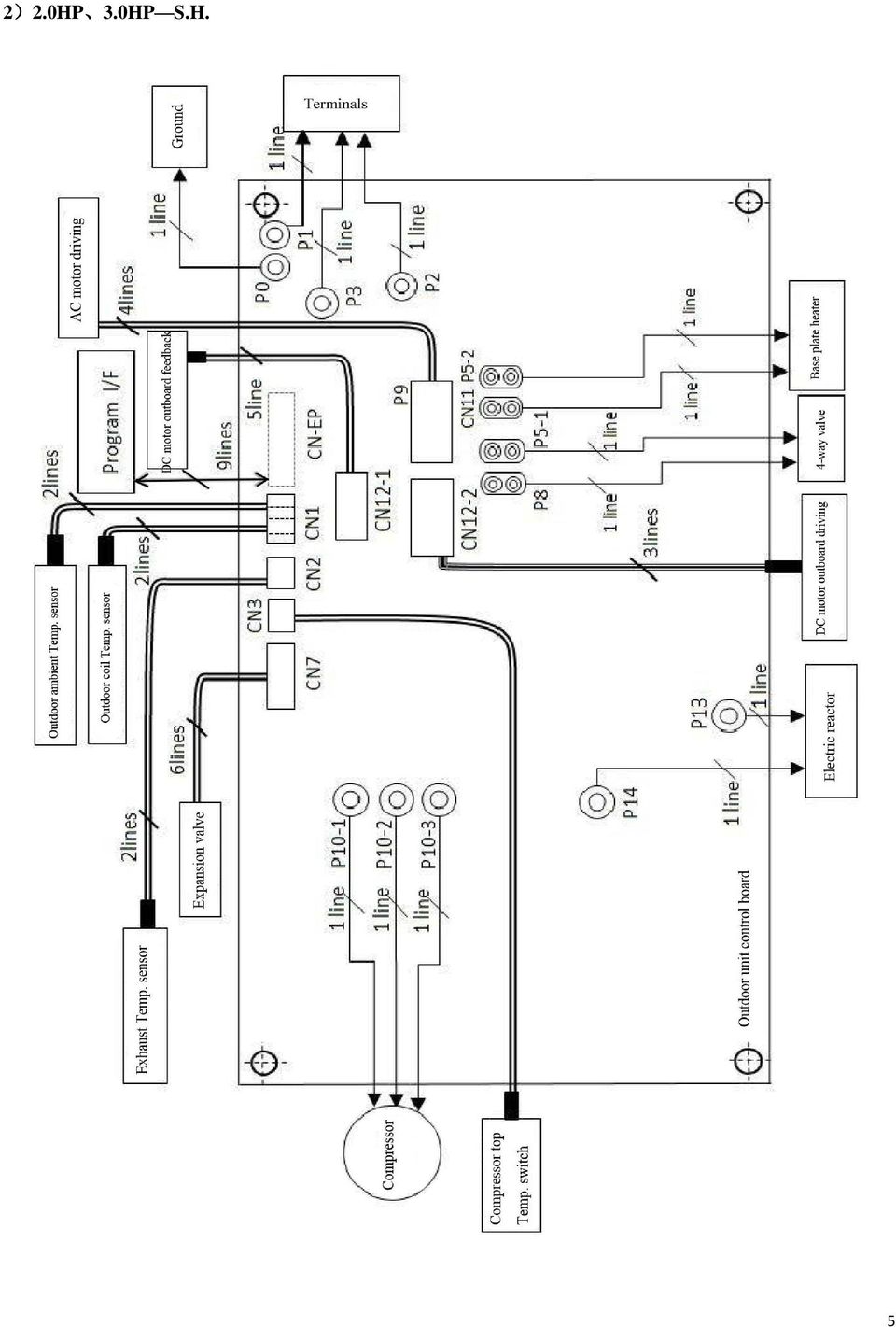
7 PC monitor DRM-COM DRM1 DRM2 DRM3 COMP. top Temp protection Suction Temp sensor Outdoor ambient Temp sensor Out door coil Temp sensor Exhaust Temp. sensor Expansion valve (Blue) (White) (Red) DRM-COM DRM1 DRM2 DRM3 COMP. top Temp protection Suction Temp sensor Outdoor ambient Temp sensor Out door coil Temp sensor Exhaust Temp. sensor Expansion valve (Red) (White) (Blue) 3)1.0HP 1.5HP R.J. COMP. To indoor unit CN409 For programming U405 IPM CN7 (LEV) CN2 (OHT) P10-3(W) P10-2(V) CN1 (OPTOAT) CN12 CN3 (ORQ)(OVT) P9 CN12-1 (DC fan motor feedback) CN13 wu v CN12-2 CN401 (485-COM) P5-1 P8 (VAL) CN11 P11-1 P11-2 (HEAT) P2 (CAN-Blue) C N L H CN410 (OUTFAN) P1 (ACL-Brown) P3 (S-Black) CN407 For EEPROM programming Q403 IGBT DN401 rectifier D412 Fast recovery diode P 14 (L) P13 (L) P10-1(U) P00 P01 Electric reactor 4)2.0HP-3.0HP R.J. COMP. To indoor unit CN409 For programming CN407 For EEPROM programming Q403 IGBT U603 IPM D412 Fast recovery diode DN401 rectifier P14(L) P13(L) CN7 (LEV) P10-1(U) P10-2(V) P10-3(W) CN2 (OHT) CN1 CN12 CN3 (OPTOAT)(ORQ) (OVT) P9 (DCFAN) CN13 CN11 (HEAT) C N L H CN410 (OUTFAN) P5-1 P8 (VAL) CN401 (485-COM) PC monitor P2 (ACN) P00 P01 P3 (S) P1 (ACL) Electric reactor 6
 CN2 (OHT) P10-3(W) P10-2(V) CN1 (OPTOAT) CN12 CN3 (ORQ)(OVT) P9 CN12-1 (DC fan motor feedback) CN13 wu v CN12-2 CN401 (485-COM) P5-1 P8 (VAL)")
8 Ground Neutral Live 3. Current flow. Power supply live U Indoor unit PCB Neutral Communication wire Outdoor unit PCB V W Compressor Ground Indoor unit Outdoor unit 4. Protection and fault codes Fault code: Fault type Function indicator(flash) Digital display(led) Indoor unit/ outdoor unit communication fault RUN,TIMER: blink E0 Indoor room temp. sensor(irt) RUN-1 /8 sec. E1 Indoor pipe temp. sensor (IPT) RUN-2 /8 sec. E2 Outdoor pipe temp. sensor (OPT) RUN-3 /8 sec. E3 System abnormal RUN-4 /8 sec. E4 Indoor fan motor fault RUN-6 /8 sec. E6 Outdoor temp. sensor RUN-7 /8 sec. E7 Exhaust temp. sensor RUN-8 /8 sec. E8 IPM drive and module fault RUN-9 /8 sec. E9 Outdoor fan motor fault (DC motor) RUN-10 /8 sec. EF Current sensor fault RUN-11 /8 sec. EA Indoor unit EEPROM fault RUN-12 /8 sec. EE Temp. switch fault ( on top of the compressor) RUN-13 /8 sec. EP Voltage sensor fault RUN-14 /8 sec. EU 7
 RUN-10 /8 sec.")
9 Display on outdoor PCB: The indicator alerts the fault in a cycle as such that it is bright for 0.5 seconds, dark for 0.5 seconds, blinks n times and then dark for 3 seconds. Blink times(n) 3 Over current Fault Message 4 Exhaust over-temperature protection 5 Outdoor coil (pipe) over-temperature protection Indoor unit display( LED) 7 Communication fault with indoor unit E0 8 Compressor overheat fault (compressor top switch) EP Short-circuit / open-circuit fault of outdoor temperature sensor Short circuit / open-circuit fault of outdoor heat exchanger temperature sensor Short-circuit / open-circuit fault of exhaust temperature sensor 12 Voltage sensor fault EU 13 Current sensor fault EA 16 No feedback from DC fan motor(outdoor unit) EF 17 Defrost state 19 Outdoor PCB EEPROM fault 23 System in shortage of Freon E4 25 Indoor unit room temp. sensor fault E1 26 Indoor unit pipe temp. sensor fault E2 27 Indoor PCB EEPROM fault EE 28 Indoor fan motor fault E6 32 Indoor coil defrost prevention 33 Indoor coil overheating protection 37 Drive abnormal(current sampling circuit fault) E9(P9) 39 Drive abnormal(over voltage) E9(P9) 40 Drive abnormal(under voltage) E9(P9) 41 Drive abnormal(ipm protection DC peak) E9(P9) 44 Drive abnormal(over current of phase current) E9(P9) 45 Drive abnormal(compressor phase failure protection) E9(P9) 47 Drive abnormal(compressor high frequency protection) E9(P9) E7 E3 E8 48 Remark: Temperature Temp. Drive abnormal(compressor frequency fluctuation abnormal) E9(P9) 8
 EF 17 Defrost")
10 Ⅱ. Troubleshooting 1. Voltage test and inspection. When an air conditioner has problem, first we need to test the key point voltage on the PCB. 1).Switch on the air conditioner normally. 2).Use a digital multimeter to measure the AC power supply (L, N) shown as picture 1AC-L, 2AC-N. 3). Measuring the busbar voltage between point 3 (DC+) and point 4 (DC-) as shown below, normally it should be DC 310V. 4). Test voltage +5V (5-9), +9V (6-9), +12V (7-9) and +15V (8-9). Analysis: 1) If AC power input normal but without DC output 310V, please check FUSE1 and/or rectifier DB101. 2) If DC 310V ok, but without +15V/+12V/+9V/+5V, inspect IC5 and/or transformer T1. 3) If +15V/+12V/+9V normal but without +5V, please check IC6 (7805) broken or not. If the air conditioner still can t work after inspection as above, replace the outdoor PCB please. 9
 If AC power input normal but without DC output 310V, please check FUSE1 and/or rectifier DB101. 2) If DC 310V ok, but without +15V/+12V/+9V/+5V, inspect IC5 and/or transformer T1.")
11 Voltage TEST POINT (examples): 1) :Single side printed board (SSPB) HP 1.5HP S.H. 10
 ---1.0HP 1.")
12 2) :Dual side printed board (DSPB) HP 3.0HP S.H. 11

13 2. According to the fault code (outdoor PCB blink times (n) or indoor unit LED display E*) 1) Blink 10 times (E3) 9times(E7) 11times(E8) 4times 5times Symptom cause Blink or 5times Outdoor pipe sensor fault (10 times), outdoor temp. sensor fault (9times) exhaust temp. sensor (11times) Exhaust over-temperature protection (4times) Outdoor coil over-temperature protection (5times) S/N Inspection Solve Remark 1 2 Check connector CN1 and CN2 on outdoor board, Measure the resistance of the outdoor temp. sensor: CN1-- ( 25 / 5KΩ ) test outdoor ambient /pipe temp. sensor value; CN2 --(25 / 20KΩ)test outdoor exhaust temp. sensor value; (for the other resistance value, please refer to the TEMP--Resistance sheet.) Insert again if it loose PIC 1 Replace the temperature sensor assembly if the resistance is not in standard level. 3 If the above testing is normal Replace outdoor PCB PIC 1 & Appendix 2 ODU ambient temp. sensor ODU ambient temp. sensor Exhaust temp. sensor Exhaust temp. sensor ODU Pipe temp. sensor ODU Pipe temp. sensor SSPB for DSPB for PIC 1:Position of sensor connector CN1 CN2 12
 test outdoor ambient /pipe temp. sensor value; CN2 --(25 / 20KΩ)test outdoor exhaust temp.")
14 2) Blink 13 times(ea) 3times Symptom Blink 13 times(ea) 3times Cause Current sensor fault(ct)(13times); Over current protection (3times) S/N Inspection Solve Remark 1 Check if refrigerant leakage 2 Find and repair the leakage problem and recharge refrigerant Switch on air conditioner, measure If the voltage is + 5V or 0V,replace the voltage between D21 + and GND with a digital multimeter the outdoor PCB PIC 2 SSPB for DSPB for PIC 2:Position of D21 and it s polarity mark 13

15 3) Blink 37~ 48 times(e9) Symptom Cause Blink 37~ 48times (E9) IPM drive fault or IPM module itself fault S/N Inspection Solve Remark 1 1.Check the sequence of wiring Wiring connection to U(red), V(white), W(blue) connection on the compressor inspection 2.The wiring connection tightly? Make sure the phase sequence of wiring connection to compressor correct. Insert again if loose. 1If this code E9(P9) is displayed when the compressor is started for several seconds or even not started, check the compressor connection for correctness To be sure the wiring connection on compressor correct. Blink 37 times: current sampling circuit fault Test voltage of IC8 pin-7, it should be: 2.5V±0.25V;if no, replace outdoor PCB PIC 3 and PIC 4 2 Power off and then, power on again, check the protection code. 2 Cooling/ heating normally in the beginning, but for some time it shows E9(P9), based on LED1 blink times on outdoor unit for further analysis Blink 39 times: over voltage protection Blink 41 times:ipm protection DC peak over current protection Blink 44 times: over current protection for Phase Current Blink 47 times: compressor high frequency protection Blink 48 times: compressor frequency fluctuation abnormal Test voltage between IC1 pin-7 and PIC 3 and PIC GND, it should be more than + 4.6V; 4 if no, replace outdoor PCB 1) Inspect the resistance R49: check whether its broken? 2) Check whether IPM (Q1) broken. Inspect the resistance R49: check whether its broken? PIC 5 PIC 5 Blink 45 times: compressor phase failure protection To be sure the wiring connection on For factory test compressor correct. only 3.No cooling or no heating: Check the wiring connection to compressor. 4.The compressor restart immediately after stopped, this might also cause E9(P9) protection because the cooling system is not stable. To be sure there is no false connection Try to start the air conditioner again after a longer period of stop 14
 is displayed when the compressor is started for several seconds or even not started, check the compressor connection for correctness To be sure the wiring connection on")
16 图 三 :IC8 IC1 位 置 示 意 图 ( 单 面 板 ) SSPB for PIC 3:Position of IC8 IC1(Single printed board) 15

17 图 四 :IC8 IC1 位 置 示 意 图 ( 双 面 板 ) DSPB for PIC 4: Position of IC8 IC1(Dual printed board) SSPB for DSPB for PIC 5:Position of R49, IC3 and Q1 16

18 4) Blink 7 times(e0) Symptom Cause Blink 7 times (E0) Communication fault of indoor / outdoor unit S/N Inspection Solve Remark 1 Check if the indoor and outdoor wiring connections are correct. The terminal L, N and S(1) shall correspond to each other on indoor and Replace the indoor main PIC 6 outdoor units. Measure the voltage on outdoor PCB terminal L and N (before display of E0 fault). If the voltage is 0 : 2If the L & N voltage is normal, measure the voltage between the outdoor terminal N and S. If the voltage change occurs between 0~24V (pulsating voltage) Replace the indoor main PCB (Red circle) 1 Energize and observe for approx. 10 minutes. If E0 is always displayed 3If the L & N voltage is normal, measure the voltage between the outdoor terminal N and S. If the voltage change occurs between 0~12V (pulsating voltage), but there is no 24V Replace the outdoor PCB Firstly replace the indoor 4If the L & N voltage is normal, measure the main PCB. If the fault voltage between the outdoor terminal N and S. If remains unsolved, replace the voltage has no change the outdoor PCB. 1).The indicator is dark, and+5v is normal, test voltage between N and S, If yes, replace the if there is no 0~24V pulsating voltage, resistance or please check R1,R2 whether it s opened replace outdoor PCB or shorted after switch off the air conditioner. PIC 6 (Yellow circle) PIC 7 5 Indicator on outdoor PCB 2).The indicator is dark, and also without +5V power supply: Switch off air conditioner, and inspect components as rectifier bridge---db101, fast recovery diode D84, IGBT(Q9) and IPM(Q1), check whether it broken or not If yes, replace the Component(s) or replace outdoor PCB PIC 8 3).if no damage as above 1) and 2),test voltage between DC+ and DC-, if the Replace outdoor PCB voltage is 0V 1). Replace outdoor PCB 6, if the problem cannot be solved by using the firstly, methods as above 2). if still has problem, replace the indoor PCB 17
 Replace the indoor main PCB (Red circle) 1 Energize and observe for approx. 10 minutes.")
19 PIC 6: L N S(1)on outdoor unit terminal SSPB for DSPB for PIC 7: Position of N S R1 R2 on outdoor unit SSPB for DSPB for PIC 8: Position of DB101 D84 Q9 Q1 DC+ DC- 18

20 5) Blink 27 times(ee) Symptom Blink 27 times (EE) Cause EEPROM fault(indoor outdoor) S/N Inspection Solve Remark 1 Power off and then power on, if the fault remains, it is needed to check if the indoor EEPROM installation is Install again loose or improper. 2 Power off and then power on, if the fault remains, it is needed to check if the outdoor EEPROM installation is Install again loose or improper. 3 If the installation is good, check whether there is Soldering again component(s) pseudo soldering on board 4 If the fault remains unsolved after replacement of the Test outdoor unit PCB or replace it indoor control board 5 Check up the Checksum on outdoor PCB --EEPROM (IC3), it should be correspond to the Checksum on Control Box shown as PIC 9 If no, replace outdoor PCB PIC 9 SSPB for DSPB for PIC 9:EEPROM and Checksum on PCB and Control Box. 19
 pseudo soldering on board 4 If the fault remains unsolved after replacement of the Test outdoor unit PCB or replace")
21 6) Blink 16 times(ef) Symptom Cause Blink 16 times (EF) Outdoor fan motor fault(dc fan motor) S/N Inspection Solve Remark 1 2 Power off and then power on, if the fault remains, it s needed to check the connection of CN12-1 CN12-2. Check the soldering of the connector CN12-1 CN12-2 on the PCB, it should be no pseudo soldering. 3 Replace the DC motor and check it s action. Reconnect again PIC 10 If yes, solder again. Problem has no change, replace outdoor PCB. 4 Switch off airco, and test U/V; U/W;V/W on CN12-2, there should be no short circuit happened. If yes, replace outdoor PCB PIC 10 5 Test between pins of IPM(IC13),there should be no If yes, replace outdoor PCB PIC 10 breakdown or short circuit happened. 6 Test voltage of pin 7 on IC14, it should be + 5V If no, replace outdoor PCB PIC 11 7 Test voltage of pin 22 (signal F0) on IC13, it should be + 5V If no, replace outdoor PCB PIC 11 SSPB for DSPB for PIC 10:The position of CN12-1 CN12-2 and IC13 20
22 SSPB for DSPB for PIC 11:The test pin position of IC14 IC13 3. Normally inspection 1).The indoor unit works normally but the outdoor unit does not work. Cause Analysis: a). Check if fault code is displayed: If yes, treat according to fault code. If no, check according to the following steps. b). If the outdoor fan runs normally (The outdoor fan is started 5 seconds before the compressor is started, and it is stopped 15 seconds after the compressor is stopped), the client might make wrong judgment on that the outdoor unit does not work because the compressor working frequency is low or the system is in shortage of refrigerant. Check the system cooling / heating effect and confirm if the system is in shortage of refrigerant. c).check if the resistance of each temperature sensor is in standard level. (See appendix for the temperature sensor parameters): If not, replace the temperature sensor. d).check if the indoor / outdoor and circuit board wiring. Check if the connection is good. Please tighten the wires. 2).The outdoor unit is stopped when the air conditioner has run for a period of time Cause Analysis: a).if any fault is displayed after stop: If yes, treat according to fault code. If not, check according to Step (b). b).check if the supply voltage is normal, including the voltage change when the air condition is started. If the voltage is unstable or changes too heavily, please check the power source. If no problem, check according to Step (c). c).check if the temperature sensors are normal (See appendix for the temperature sensor parameters). Check if the 21
23 resistance is in standard level. If not, replace the temperature sensor. If normal, check according to Step (d). d).check if the indoor / outdoor circuit connection and power connection are in good contact. If no, tighten the connection wires. If yes, check according to Step (e). e).check if the refrigerant is too much or too less. If yes, add refrigerant. 3). The air conditioner is tripped when it is started. Cause Analysis: a).check if the user's power source plug is correctly connected (for example, the ground wire might be wrongly connected as the neutral wire) b).check if the indoor / outdoor circuit and the wiring terminal are correctly connected, and if there is short circuiting. c).check if the outdoor circuit board, wiring terminal and power connection wires are damaged, and if there is short circuiting to the metal parts. d).check if the rectifier bridge of outdoor controller is short circuited (The short circuiting of rectifier bridge will probably cause tripping error). 4). The complete unit does not work Cause Analysis: a).if fault code is displayed: If yes, treat according to fault code. If no, check according to Step (2). b).check if the power plug has electricity. If no, check the power source. If yes, check if the fuse is good. If no, replace the fuse. If yes, check according to Step (3). c).check if the resistance of the sensors on indoor and outdoor units is in standard level. If not, replace the sensor. If yes, check according to Step (4). d).check if the indoor and outdoor communication is failed. The step is same as that for check when the indoor unit works normally but the outdoor unit does not work. 22
24 Appendix 1 The PCB difference for 1HP\1.5HP\2HP \3HP (S.H) 1. Single printed board(the difference of 1HP and 1.5HP) The difference:1 1HP-C2:1100uF C3:NG;1.5HP-C2 C3:680uF; 2 1HP-R49:R025; 1.5HP-R49:R02 2. Dual printed board(the difference of 2HP and 3HP) The difference: 3 2HP-C2 C3:850uF; 4 2HP-R49:R02; 3HP-C2 C3:1100uF; 3HP-R49:R01 23
25 Appendix 2 AD value of the sensor ( outdoor Temp. sensor and outdoor pipe temp. sensor) R25 =5KΩ±2% B25 /50 =3470±2% TEMP. R(Kohm) Sensor Sensor Sensor TEMP R(Kohm) TEMP R(Kohm) voltage voltage voltage
26 AD value of the sensor (Exhaust Temp. sensor) R85 =2.113KΩ±3% B25 /85 =4000±2% TEMP. R(Kohm) Sensor Sensor Sensor TEMP R(Kohm) TEMP R(Kohm) voltage voltage voltage
27 Appendix 3 Silk-printed label on outdoor PCB Name of connector Connector label description AC power input-- L P1 AC-L AC power input-- N P2 AC-N Relay label Remark Communication wire to indoor unit P3 S Black GND P0 GND Outgoing L after filter P4 L K1 Outgoing N after filter P5 N Multi-marked as P5-1 P5-2 4-way valve output P8 VAL K4 Outdoor fan motor control HIGH speed P9-1 H K2 Outdoor fan motor control LOW speed P9-2 L K3 Capacitor of fan motor P9-3 C Compressor control phase U P10-1 U Compressor control-- phase V P10-2 V Compressor control-- phase W P10-3 W Inductance connector for PFC control P13 P14 L DC fan motor connector-1 CN12-1 Fan speed feedback DC fan motor connector-2 CN12-2 Fan motor (U V W) driving Pipe temp. sensor CN1 Pin1 Pin2 Outdoor temp. sensor CN1 Pin3 Pin4 Exhaust temp. sensor Compressor top thermostat Socket of electronic expansion valve CN2 CN3 CN7 Auxiliary heater CN11 HEATER 26
28 Appendix 4 Cautions on Replacement of PCB Boards When replace outdoor PCB, caution should be taken as follow. 1). Before replacing the outdoor PCB, it must be confirmed that this is the right and qualified one match to the air conditioner to be repaired. 2). Power off air conditioner first before the process of PCB disassembly and/or installation, while operating personnel must wear anti-static discharge wrist strap or gloves. It is prohibited to make any measures directly touching PCB before static discharging. 3) Pay attention to the PCB waterproof, moisture-proof and dust-proof and components fasten, if only to replace the on-board components, you must refill yellow or silicone gel scratched 4) The wire s direction and fixed should be made as it s original alignment after PCB installation. Each wires plug must be inserted in place, to be sure all of the connectors connect/insert to PCB correctly. It is forbidden to pull the ends of the wires too tightly, some looseness required to prevent circuit board broken. 5) The outdoor PCB mostly has strong electrical parts and using some isolated control, but many with strong electrical circuit Common GND, pay attention to personal safety during operation. 6) Because of the short distance between Strong and Weak electrical part, pay attention to security issues as measure GND during maintenance. 7) Due to large outdoor PCB electrolytic capacitor(s), the capacitor(s) still have a lot of electricity needs time to release while power off, and normally fully discharge needs about 30 seconds, please be patient capacitor discharge before you start working, or you can use an external load (such as electric iron, etc.) between DC-, DC+ for fast discharging. After the charge exhausted and tested by Analog Multimeter RX10K, the pointer should refer to 0, and then slowly retreated, otherwise the electrolytic capacitor broken. 8) Before repairs must have some knowledge of the circuit, fully understand the Structure of control board, and the function of each parts. 9) The cable sequence from indoor to outdoor must correct, otherwise it will be unable to work, besides additional damage maybe happened to PCB. Removing the screws should pay attention to protect against foreign objects such as screws or other solder falling to the board or the electrical control box, if that it must be cleared up. 10) After repairing, first confirm each voltage is normal after power on, then operate the air conditioner to confirm function. 27
29 Appendix 5 Photos of outdoor unit PCB 1A. 1.0HP,1.5HP---R.J. 1B. 1.0HP,1.5HP ---R.J. 28
30 2A. 2.0HP,3.0HP ---R.J. 2B. 2.0HP, 3.0HP---R.J. 29
31 3A. 1.0HP,1.5HP --- EUROPE ---R.J. 3B. 1.0HP,1.5HP --- EUROPE ---R.J. 30
32 4A. 1.0HP,1.5HP AUSTRALIA---R.J. 4B. 1.0HP,1.5HP ---AUSTRALIA---R.J. 31
33 5A. 1.0HP---S.H. 5B. 1.0HP---S.H. 32
34 6A. 1.5HP---S.H. 6B. 1.5HP---S.H. 33
35 7A. 2.0HP---S.H. 7B. 2.0HP---S.H. 34
36 8A. 3.0HP---S.H. 8B. 3.0HP---S.H. 35
Repair Guideline for SANYO New Erp. DC Inverter Air Conditioner (Published in May, 2013)
") Repair Guideline for SANYO New Erp DC Inverter Air Conditioner (Published in May, 2013) Contents I. Electronic Control of DC Inverter Air Conditioner 2 1. Main parts of the electronic control of DC inverter
Repair Guideline for SANYO New Erp DC Inverter Air Conditioner (Published in May, 2013) Contents I. Electronic Control of DC Inverter Air Conditioner 2 1. Main parts of the electronic control of DC inverter
Repair Guideline for TCL DC Inverter Air Conditioner
 Repair Guideline for TCL DC Inverter Air Conditioner Contents I. Electrical Control of Inverter Air Conditioner 2 1. Main compositions of the electrical control of inverter air conditioner 2 2. Wiring
Failure code manual. content
 Failure code manual content 一 wall split AC series 2 二 floor standing AC series. 4 三 portable AC series.. 5 四 dehumidifer 6 五 DC inverter single split series...7 六 DC inverter multi-split series 10 1 一
14. Troubleshooting Guide
 14. Guide 14.1 Refrigeration Cycle System In order to diagnose malfunctions, ensure the air conditioner is free from electrical problems before inspecting the refrigeration cycle. Such problems include
Service manual. The voltage in P3 and P4 in outdoor PCB is high voltage about 310V The voltage in P5 and P6 in outdoor PCB is high voltage about 310V
 Resistance The voltage in P3 and P4 in outdoor PCB is high voltage about 310V The voltage in P5 and P6 in outdoor PCB is high voltage about 310V 9.2 Troubleshooting for indoor unit E0 E1 E2 E3 E5 E6 P0
LG Air Conditioning - Universal Split Fault Codes Sheet. Universal Split Systems
 Universal Split Systems If there is a fault on any LG Universal unit, a two digit number will appear on the remote controllers led display. If the unit does not have a remote controller the fault will
SERVICE MANUAL. Room Air Conditioner Multi Split type Outdoor unit /R410A DC Inverter/
 SERVICE MANUAL Room Air Conditioner Multi Split type Outdoor unit /R410A DC Inverter/ FS2MI-147HFD FS2MI-187HFD FS3MI-217HFD FS3MI-277HFD FS4MI-277HFD FS4MI-367HFD FS5MI-367HFD NOTE: Before servicing the
13. Troubleshooting. Indoor unit s LED indication of Corona DC inverter unit. Indoor unit s LED indication of Alfa DC inverter unit
 Troubleshooting 13. Troubleshooting Indoor unit s LED indication of Corona DC inverter unit MCAC-HTSM-2007-11 E0 E1 E2 E3 E5 E6 P0 P1 P2 P3 P5 EEPROM error outdoor communication error Zero-crossing examination
LG Air Conditioning Multi F(DX) Fault Codes Sheet. Multi Split Units
 Fault Codes Sheet. Multi Split Units") Multi Split Units If there is a fault on any LG Multi unit, an Error mark is indicated on the display window of the indoor unit, wired-remote controller, and LED s of outdoor unit control board. A two
Multi Split Units If there is a fault on any LG Multi unit, an Error mark is indicated on the display window of the indoor unit, wired-remote controller, and LED s of outdoor unit control board. A two
Haier Air conditioner
 For Europe Haier Air conditioner HAND in HAND HIGHER and HIGHER Page:1 For Europe HSU-09/12HVA103/R2(DB) HSU-09/12RHA103/R2(DB) Page:2 Error Codes and Description indoor and outdoor display(1) indoor Code
Indoor coil is too warm in cooling mode or too cold in heating mode. Reversing valve or coil thermistor is faulty
 Codes Room Air Conditioner range: Indoor unit alarm s If timer lamp flashes for 1 second on, 1 second off, this indicates pre heating on the coil during heating mode and is not an error. If timer lamp
CONTENTS 1. IMPORTANT NOTICE 2 2. TECHNICAL SPECIFICATION 3 3. OPERATION DETAILS 4 4. WIRING DIAGRAM 11 5. EXPLOSION VIEW 12 6.
 TCL WALL MOUNTED SPLIT-TYPE AIR CONDITIONERS SERVICE MANUAL No.TE051220 Models TAC-09CHSA/GI TAC-12CHSA/GI CONTENTS 1. IMPORTANT NOTICE 2 2. TECHNICAL SPECIFICATION 3 3. OPERATION DETAILS 4 4. WIRING DIAGRAM
Technical service manual 2009
 MULTI SPLIT TYPE, HEAT PUMP AIR CONDITIONERS Technical service manual 2009 KSIM MULTI ZONE SERIES R410A DC Inverter multi Series Models KSIM20912-H216 KSIM30912-H216 KSIM40912-H216 CONTENT 1. Product features
10.1 Indoor Unit Error Display
 10.1 Indoor Unit Error Display Display E0 E1 E2 E3 E5 E6 P0 P1 P2 P4 LED STATUS EEPROM parameter error Indoor / outdoor units communication protection Zero-crossing signal error Fan speed out of control
Technical service manual
 GD Midea Refrigeration Equipment Co.,Ltd ODMI-A-1202 MULTI SPLIT TYPE, HEAT PUMP AIR CONDITIONERS Technical service manual R410A Multi DC inverter 220~240V-1Ph-50Hz Outdoor units Models M2OC-14HRDN1 M2OC-14HRDN1-Q
SERVICE INSTRUCTION R410A. WALL MOUNTEDtype INVERTER SPLIT TYPE ROOM AIR CONDITIONER. Models Indoor unit Outdoor unit
 SERVICE INSTRUCTION SPLIT TYPE ROOM AIR CONDITIONER WALL MOUNTEDtype INVERTER Models Indoor unit Outdoor unit ASYG07LECA ASYG09LECA ASYG12LECA ASYG14LECA AOYG07LEC AOYG09LEC AOYG12LEC AOYG14LEC R410A CONTENTS
543-0032-00, 943-0032-00. User s Manual
 543-0032-00, 943-0032-00 User s Manual 1 Comfort Alert Diagnostics Faster Service And Improved Accuracy The Comfort Alert diagnostics module is a breakthrough innovation for troubleshooting heat pump and
TAS-18MVHN/O TAS-27MVHN/O TAS-36MVHN/O
 SERVICE MANUAL AIRCONDITIONER DC INVERTER MULTI TYPE TAS-18MVHN/O TAS-27MVHN/O TAS-36MVHN/O DC MULTI OUTDOOR UNITS CONTENTS 1. General information of Outdoor Units... 3 2. Dimensions... 4 3. Wiring Diagram...
R22. K Control. Indoor Unit. Nomenclature. Compatibility PL H 3 G K H B. Unit style Heat Pump Horse Power
 R22. K Control. Indoor Unit. Nomenclature. PL H 3 G K H B Compatibility Unit style Heat Pump Horse Power Control Boost Heaters R22. K Control. Outdoor Unit. Nomenclature. PU H 3 Y K A Compatibility Outdoor
FILE NO. SVM-07013 11. HOW TO DIAGNOSE THE TROUBLE
 FILE. SVM-070. HOW TO DIAGSE THE TROUBLE The pulse motor circuits are mounted to both indoor and outdoor units. Therefore, diagnose troubles according to the trouble diagnosis procedure as described below.
Si10-417_C. Pocket Manual. Service Diagnosis SPLIT & MULTI
 Pocket Manual Service Diagnosis SPLIT & MULTI Service Diagnosis SPLIT & MULTI 1. Troubleshooting with LED...5 1.1 Indoor Unit... 5 1.2 Outdoor Unit... 10 2. Troubleshooting by Symptoms...11 2.1 Air conditioner
Split and Multi Split air conditioners Service information
 Split and Multi Split air conditioners Service information Programming LG wired controllers 2 New type 2 Old type 7 Fault codes 9 Wall units (single split) 9 Universal split and multi split 10 Detailed
Service manual. Website: www.andico.com.au CAUTION - BEFORE SERVICING THE UNIT, READ THE SAFETY - PRECAUTIONS IN THIS MANUAL.
 Website: www.andico.com.au Service manual CAUTION - BEFORE SERVICING THE UNIT, READ THE SAFETY - PRECAUTIONS IN THIS MANUAL. - ONLY FOR AUTHORISED SERVICE PERSONNEL. MODELS: MPK1-09CR-QB8 MPK1-12ER-QB6
SERVICE MANUAL FOR 6535 SERIES TWO TON HIGH EFFICIENCY PACKAGED HEAT PUMPS
 SERVICE MANUAL FOR 6535 SERIES TWO TON HIGH EFFICIENCY PACKAGED HEAT PUMPS TABLE OF CONTENTS 1. Warnings...2 2. Accessibility Of Appliance...3 3. Unit Dimensions And Specifications...3 4. Unit Specifications
SERVICE INSTRUCTION R410A. WALL MOUNTEDtype SPLIT TYPE ROOM AIR CONDITIONER INVERTER. Models Indoor unit Outdoor unit AOU 9RLFW AOU12RLFW AOU15RLS
 SERVICE INSTRUCTION SPLIT TYPE ROOM AIR CONDITIONER WALL MOUNTEDtype INVERTER Models Indoor unit Outdoor unit ASU 9RLF ASURLF ASU5RLS AOU 9RLFW AOURLFW AOU5RLS R40A CONTENTS. DESCRIPTION OF EACH CONTROL
NO-FROST CUSTOMER SUPPORT INFORMATION INFORMATION ON THE NO-FROST TECHNOLOGY WHITE GOODS
 INFORMATION INFORMATION ON THE TECHNOLOGY The -Frost refrigerators are different from the other static refrigerators in terms of their operational system. In normal refrigerators, in the freezing section,the
PANASONIC TROUBLE SHOOTING GUIDE
 A General Guide To Room Style Products Pipework Pipe sizes and lengths should be as the relevant Technical Guide Both lines should be insulated No line accessories or oil traps should be fitted In cooling
Heater and Air Conditioner, Blend Air System, Troubleshooting 83.06
 A/C Performance Diagnosis Problem Warm Airflow When the Air Conditioner is On, A/C Not Working, or Poor A/C Performance (dash outlet temperature is too high) Problem Warm Airflow When the Air Conditioner
AIR CONDITIONER INSTALLATION MANUAL
 INSTALLATION MANUAL AIR CONDITIONER Please read this installation manual completely before installing the product. Installation work must be performed in accordance with the national wiring standards by
How To Use A Power Supply Unit (Upu)
") BRAVER UPS (Uninterruptible Power System) User s Manual Safety CAUTION! This UPS utilizes voltages that may be hazardous. Do not attempt to disassemble the unit. The unit contains no user replaceable parts.
BRAVER UPS (Uninterruptible Power System) User s Manual Safety CAUTION! This UPS utilizes voltages that may be hazardous. Do not attempt to disassemble the unit. The unit contains no user replaceable parts.
SERVICE MANUAL OUTDOOR UNIT. No. OBH590 REVISED EDITION-B. Models HFC
 SPLIT-TYPE AIR CONDITIONERS Revision B: MUZ-EF25/35/42/50VE - E2 and MUZ-EF25/35VEH - E2 have been added. Please void OBH590 REVISED EDITION-A. OUTDOOR UNIT SERVICE MANUAL HFC utilized R410A. OBH590 REVISED
800-292-3279 916 638-0828
 800-292-3279 916 638-0828 http://easycleansystems.com/heaters/heater-parts.html VAL6 KBE5S and KBE5L Service manual KBE5S 1 2 Specifications Type VAL6 KBE5S Heat Output 111,000BTU/h Fuel Kerosene, Diesel
TECHNICAL SERVICE DEPARTMENT Technical Service Bulletin 1-800-432-8373. 2 Inch PowerVent LED Indicator Explanations & Troubleshooting Table
 New Robertshaw control valve was introduced in May 2008 as a replacement part. See last page for troubleshooting this replacement part. All voltage inputs are 120V. All electrical connectors are Molex
Thermo Top - Troubleshooting Tree
 Thermo Top - Troubleshooting Tree 07-15-2002 CAUTION Troubleshooting requires comprehensive knowledge about the structure and theory of operation of the Thermo Top heater. Troubleshooting and repairs may
ECEN 1400, Introduction to Analog and Digital Electronics
 ECEN 1400, Introduction to Analog and Digital Electronics Lab 4: Power supply 1 INTRODUCTION This lab will span two lab periods. In this lab, you will create the power supply that transforms the AC wall
SERVICE MANUAL AE-X2M14LR MULITI SPLIT TYPE ROOM AIR CONDITIONERS (OUTDOOR UNIT) MODEL. No. S2038AEX2MLRT CONTENTS AEX2M14LR
 MODEL. No. S2038AEX2MLRT CONTENTS AEX2M14LR") TopPage AEX2M14LR SERVICE MANUAL. S2038AEX2MLRT MULITI SPLIT TYPE ROOM AIR CONDITIONERS (OUTDOOR UNIT) MODEL AE-X2M14LR In the interests of user-safety (Required by safety regulations in some countries)
TopPage AEX2M14LR SERVICE MANUAL. S2038AEX2MLRT MULITI SPLIT TYPE ROOM AIR CONDITIONERS (OUTDOOR UNIT) MODEL AE-X2M14LR In the interests of user-safety (Required by safety regulations in some countries)
HVAC SYSTEM (AUTO A/C) (DIAGNOSTICS) AC
 (DIAGNOSTICS) AC") HVAC SYSTEM (AUTO A/C) (DIAGNOSTICS) AC Page. Basic Diagnostic Procedure.... General Description...3 3. Electrical Components Location...6 4. A/C Control Module I/O Signal...8 5. Self-diagnosis...0 6.
HVAC SYSTEM (AUTO A/C) (DIAGNOSTICS) AC Page. Basic Diagnostic Procedure.... General Description...3 3. Electrical Components Location...6 4. A/C Control Module I/O Signal...8 5. Self-diagnosis...0 6.
MP-4000 Alarm List (Software version 2.4.3 or later)
") Service Bulletin SUBJECT: MP4000 Alarm s BULLETIN: C 100 DATE: June 19, 2013 ALARM LIST Where it is possible the alarm number is kept the same as for MP-3000. MP-3000 holds alarm number from 0 to 127.
Service Bulletin SUBJECT: MP4000 Alarm s BULLETIN: C 100 DATE: June 19, 2013 ALARM LIST Where it is possible the alarm number is kept the same as for MP-3000. MP-3000 holds alarm number from 0 to 127.
Technical Information
 Date of last update: Oct-11 Ref: D7.8.4/1011/E Application Engineering Europe CORESENSE DIAGNOSTICS FOR STREAM REFRIGERATION COMPRESSORS CoreSense Diagnostics for Stream Refrigeration Compressors... 1
I. R. D. T INSTITUTE OF RESEARCH DEVELOPMENT AND TRAINING
 I. R. D. T INSTITUTE OF RESEARCH DEVELOPMENT AND TRAINING SYLLABUS SIX MONTHS FULL TIME Repair and Maintenance of Electrical gadgets EFFECTIVE FROM:- UNDER DEVELOPMENT Prepared By: Curriculum Development
A.Y. McDonald Mfg. Co. Troubleshooting Submersible and Jet Pumps
 A.Y. McDonald Mfg. Co. Troubleshooting Submersible and Jet Pumps Troubleshooting Submersible Pumps Fuse overload or circuit breaker trips when motor is started 1. Incorrect line voltage. Check the line
User s Manual AURORA 1.2K/2.2K
 User s Manual AURORA 1.2K/2.2K Uninterruptible Power System Safety CAUTION This UPS utilizes voltages that may be hazardous. Do not attempt to disassemble the unit. The unit contains no user serviceable
SECTION 26 29 23 VARIABLE FREQUENCY DRIVES
 SECTION 26 29 23 VARIABLE FREQUENCY DRIVES PART 1 GENERAL 1.01 SCOPE A. Furnish and install individual freestanding variable frequency AC drives (VFD) as shown on the Drawings and specified herein. 1.02
1 4. 3 4-2 ABNORMAL OPERATION. 4-2-1 Error code Display. Specifics Error Code. Subsection Error Code. Subsection and Specifics Error code target
 4-2 ABNORMAL OPERATI 4-2-1 An is represented by 3 digit characters. The first 2 digit means the subsection, and the last 1 digit means the specifics. Ex.) Indoor unit Network communication Error Subsection
AIR CONDITIONING SYSTEMS
 Installation Manual for DRED Interface (DRC-101A) About DRED Interface The DRED interface (DRC-101A) allows the air-conditioner to go in to Demand Response Mode in response to signals sent from the Electric
Midea Commercial Air Conditioner Malfunction Handbook
 Midea Commercial Air Conditioner Malfunction Handbook May 1, 2008 Customer Service Philosophy of Midea Air Conditioner Service Target: 100% Customer Satisfaction Service Standard: 100% Earnestness Service
SERVICE MANUAL SPLIT SYSTEM ROOM AIR CONDITIONER SHARP CORPORATION SHARP CORPORATION CONTENTS
 SERVICE MANUAL SPLIT SYSTEM ROOM AIR CONDITIONER INDOOR UNIT AH-129 AH-MP14 OUTDOOR UNIT AU-129 AU-MP14 CONTENTS SPECIFICATIONS...2 EXTERNAL DIMENSIONS...4 WIRING DIAGRAMS...5 ELECTRICAL PARTS...6 MICROCOMPUTER
Air conditioning, electrical testing
 just a test. Air conditioning, electrical testing 01-253 Wire and component test using VAG1598 A test box Special tools and equipment VAG 1598 A test box and VAG 1598/11 adapter cable and VAG 1598/12 VAG1526
ELECTRONIC THERMOSTAT AND THERMOMETER With SPEED CONTROL
 148 OLD CONCORD TURNPIKE, BARRINGTON NH 03825 USA TEL (603) 868-5720 FAX (603) 868-1040 1-800-435-6708 E-Mail:sales@seafrost.com www.seafrost.com ELECTRONIC THERMOSTAT AND THERMOMETER With SPEED CONTROL
SERVICE MANUAL REFRIGERATION
 SERVICE MANUAL REFRIGERATION ELECTROLUX HOME PRODUCTS S.p.A. Publication no. Spares Operations Italy 599 36 16-90 Corso Lino Zanussi, 30 031117 I - 33080 PORCIA / PN (ITALY) ITZ/SERVICE/AA Fax +39 0434
AUTOMATIC CONTROL HEATING, VENTILATION AND AIR CONDITIONING SYSTEM
 SECTION 7D AUTOMATIC CONTROL HEATING, VENTILATION AND AIR CONDITIONING SYSTEM TABLE OF CONTENTS Description and Operation... 7D- General... 7D- FATC Control... 7D- FATC Input/Output Routing Diagram...
ESPD8-301R MODEL ESP-D FAN COIL UNIT TROUBLESHOOTING GUIDE
 ESPD8-301R MODEL ESP-D FAN COIL UNIT TROUBLESHOOTING GUIDE Protected by one or more of the following U.S. Patents (3,507,354; 3,575,234; 3,596,936; 3,605,797; 3,685,329; 4,045,977; 4,698,982; 926,673 and
sip Sanyo Modbus Guide Technical Specification Pinouts, Cable Connections & Wiring Issue 2: February 2009 Synapsys Solutions Ltd, all rights reserved
 Sanyo Section : Section : Section : Section : Section : sip Modbus Guide Configuration Modbus Table Technical Specification Pinouts, Cable Connections & Wiring Alarm Fault Codes Issue : February 009 Section
SERVICE MANUAL 12VDC WALL THERMOSTAT AIR CONDITIONING SYSTEMS ROOFTOP UNITS ONLY
 SERVICE MANUAL 12VDC WALL THERMOSTAT AIR CONDITIONING SYSTEMS ROOFTOP UNITS ONLY! WARNING - SHOCK HAZARD! TO PREVENT THE POSSIBILITY OF SEVERE PERSONAL INJURY, DEATH, OR EQUIPMENT DAMAGE DUE TO ELECTRICAL
EVANS ELECTRONIC TEMPERATURE CONTROL TROUBLESHOOTING GUIDE for systems equipped with electric coolant valve and external PC board.
 EVANS ELECTRONIC TEMPERATURE CONTROL TROUBLESHOOTING GUIDE for systems equipped with electric coolant valve and external PC board. This Troubleshooting Guide covers the electric coolant valve and control
Operational Overview and Controls Guide
 DOCUMENT: ECSEQ2-1 EFFECTIVE: 02/14/07 SUPERSEDES: 02/26/03 Operational Overview and Controls Guide Standard Two or Three Pump Type VFD Booster Controls 6700 Best Friend Road. Norcross, GA 30071. (770)
SERVICE MANUAL MUZ-FE09NA MUZ-FE12NA MUZ-FE18NA OUTDOOR UNIT. No. OBH543 REVISED EDITION-A. Models HFC
 SPLIT-TYPE AIR CONDITIONERS Revision A: MUZ-FE18NA has been added. Please void OBH543. OUTDOOR UNIT SERVICE MANUAL HFC utilized R410A. OBH543 REVISED EDITION-A Models MUZ-FE09NA MUZ-FE12NA MUZ-FE18NA Indoor
Oil and Coolant Circulating Heating System. Model - OCSM
 Oil and Coolant Circulating Heating System Model - OCSM Installation & Operation Manual 216280-000 REV 2 Identifying Your System The HOTSTART heating system is designed to heat fluids for use in marine
HEAT SIPHON ANSWERBOOK
 ERROR CODES -Displayed on Player Board There are three different types of error codes displayed by the Digital Player Controller" 1 WARNING CODE - The Warning Code is displayed for the duration the error
Simple Self-Diagnosis by Malfunction Code
 Simple Self-Diagnosis by Code After Sales Service Division (SM-TS2) Detail Division 0 Indoor Unit System Others A C E F H J L P U M 7 8 9 External device activated (unified) Protection devices activated
How To Wire Wire Wire A Power Supply On A Powerline (Powerline) From A Powerstation To A Powerplant (Powerplant) (Powerplant) (Control Board) (Wire) (Switchboard) (Wired) (
 From A Powerstation To A Powerplant (Powerplant) (Powerplant) (Control Board) (Wire) (Switchboard) (Wired) (") SERVICE MANUAL Order No.AC0S020V0 Wall mounted Type DC Inverter EA-Series Model No. HSU09VHJ(DB) WARNING This service information is designed for experienced repair technicians only and is not designed
SERVICE MANUAL Order No.AC0S020V0 Wall mounted Type DC Inverter EA-Series Model No. HSU09VHJ(DB) WARNING This service information is designed for experienced repair technicians only and is not designed
INSTALLATION MANUAL. Address card EKAC10B
 INSTALLATION MANUAL 88 44 µchiller compact 70 64 4a 4b G G0 power supply G G0 power supply 50 5 50 5 4a 4b 5a 5b 4 5a 5b Installation manual READ THIS MANUAL ATTENTIVELY BEFORE STARTING UP THE UNIT. DO
Air Conditioning Sign-Off Sheet
 Air Conditioning Sign-Off Sheet Printed Technician Name Address Social Security Number Telephone Number City State Zip Code Install Or Verify The Accuracy Of An Air Conditioner s Installation The candidate
SERVICE MANUAL. Room Air Conditioner Multi Split Wall-Mounted Type Indoor. FSAI-Pro-91AE2 FSAI-Pro-121AE2 FSAIF-Pro-181AE2
 SERVICE MANUAL Room Air Conditioner Multi Split Wall-Mounted Type Indoor FSAI-Pro-91AE2 FSAI-Pro-121AE2 FSAIF-Pro-181AE2 NOTE: Before servicing the unit, please read this at first. Always contact with
01-3 0000-00 6810-20 AIR CONDITIONING SYSTEM 1. FFH SPECIFICATION AIR CONDITIONING SYSTEM RODIUS 2004.09
 0000-00 01-3 6810-20 1. FFH SPECIFICATION 01-4 0000-00 2. SYSTEM LAYOUT AND COMPONENTS 0000-00 01-5 01-6 0000-00 3. FFH GENERAL INFORMATION The system is to increase the coolant temperature quickly by
Kit 106. 50 Watt Audio Amplifier
 Kit 106 50 Watt Audio Amplifier T his kit is based on an amazing IC amplifier module from ST Electronics, the TDA7294 It is intended for use as a high quality audio class AB amplifier in hi-fi applications
ALL IN ONE. Heat Pump Water Heater
 ALL IN ONE Heat Pump Water Heater INSTALLATION AND OPERATION INSTRUCTIONS Please read this user s manual carefully before operate the unit. www.airtradecentre.com CONTENTS A. IMPORTANT REMARKS ------------------------------------------------------------------------------------------------
Section 7. Evaporator thermistor. Under-and-over pressure safety switches. Connections to the ECU
 Automatic Temperature Control Diagnosis and Repair Diagnosis of Automatic A/C Systems The most common automatic A/C system malfunctions tend to be the result of basic air conditioning problems. These problems
SERVICE MANUAL MUZ-GE25VA - E1 MUZ-GE25VAH - E1 MUZ-GE35VA - E1 MUZ-GE35VAH - E1 MUZ-GE42VA - E1 MUZ-GE42VAH - E1 MUZ-GE50VA - E1 MUZ-GE50VAH - E1
 SPLIT-TYPE AIR CONDITIONERS Revision A: MUZ-GE42/50VA(H) - E1 has been added. Please void OBH516. OUTDOOR UNIT SERVICE MANUAL HFC utilized R410A. OBH516 REVISED EDITION-A Models MUZ-GE25VA - E1 MUZ-GE25VAH
USER S MANUAL. MaxPower 400-600 UPS. Uninterruptible Power System 28-2MAXPO0018
 USER S MANUAL MaxPower 400-600 UPS Uninterruptible Power System 28-2MAXPO0018 IMPORTANT SAFETY INSTRUCTIONS SAVE THESE INSTRUCTIONS This manual contains important instructions for models MaxPower 400 and
Portable Air Conditioner
 Portable Air Conditioner Owner's Manual Model:3 in 1 12,000 Btu/h Series 3 Please read this owner s manual carefully before operation and retain it for future reference. CONTENTS 1. SUMMARY...1 2. PORTABLE
SERVICE MANUAL. Model No. HSU24VHJ(DB) Wall mounted Type DC Inverter EA-Series WARNING. Haier Group. Order No.AC1101S021V0
 Wall mounted Type DC Inverter EA-Series WARNING. Haier Group. Order No.AC1101S021V0") SERVICE MANUAL Order No.AC1101S021V0 Wall mounted Type DC Inverter EA-Series Model No. HSU24VHJ(DB) WARNING This service information is designed for experienced repair technicians only and is not designed
SERVICE MANUAL Order No.AC1101S021V0 Wall mounted Type DC Inverter EA-Series Model No. HSU24VHJ(DB) WARNING This service information is designed for experienced repair technicians only and is not designed
GLOLAB Universal Telephone Hold
 GLOLAB Universal Telephone Hold 1 UNIVERSAL HOLD CIRCUIT If you have touch tone telephone service, you can now put a call on hold from any phone in the house, even from cordless phones and phones without
technical data air conditioning systems RXS20-25-35E (single phase) FBQ-B8V1-B8V3B Split Heat Pump Condensing Units Split Sky Air
 FBQ-B8V1-B8V3B Split Heat Pump Condensing Units Split Sky Air") technical data RXS20-25-35E FBQ-B8V-B8V3B (single phase) Split Heat Pump Condensing Units air conditioning systems Split Sky Air Outdoor Units R-40A RXS-E2VB Split Sky Air Outdoor Units Features O u t
technical data RXS20-25-35E FBQ-B8V-B8V3B (single phase) Split Heat Pump Condensing Units air conditioning systems Split Sky Air Outdoor Units R-40A RXS-E2VB Split Sky Air Outdoor Units Features O u t
E2 Series Electric Furnaces
 E2 Series Electric Furnaces Service Manual Table of Contents Electrical Requirements... 10 Codes, Specifications Requirements... 10 Connection Supply Service Wires... 10 Furnace Sequence of Operation...
Model: AC-S13CG x 2. Model No: AC-S13CGx2.doc Version 1.0
 Air Conditioner Service Manual 2 3 Model: AC-S13CG x 2 3 Content Technical specification.. 4 Performance curve.5 Outline & dimension of indoor unit..10 Outline & dimension of outdoor unit 11 Exploded view
6. Diagnostics for A/C System Malfunction
 6. A: A/C OR SELF-DIAGNOSIS SYSTEMS DO NOT OPERATE TROUBLE SYMPTOM: Set temperature is not indicated on the display, switch LEDs are faulty or switches do not operate. Self-diagnosis system does not operate.
YSmart Technology Co.,Ltd
 YSmart Technology Co.,Ltd GWV Series Grid Tie Microinverter User Manual The copyright of this user manual belong to YSmart TechnologyCompany Limited. Without the written permission of the copyright holder,
SOLAR POWER CONDITIONER Service Manual
 SOLAR POWER CONDITIONER Service Manual JH-1600E Released in May 2009 Version: V00 TABLE OF CONTS Important Service Safety Precautions 2 Warning.. 3 General Information.. 5 1 System Overview... 5 2 Overview
Charge Regulator SCR 12 Marine
 Charge Regulator SCR 12 Marine Manual Many thanks for purchasing a superwind product. The SCR 12 Marine is a charge regulator of highest quality and will perfectly and reliably charge your batteries for
SERVICE INSTRUCTION R410A. SPLIT TYPE ROOM AIR CONDITIONER Universal Floor / Ceiling Duct / Cassette Wall Mounted / Floor type INVERTER MULTI
 SERVICE INSTRUCTION SPLIT TYPE ROOM AIR CONDITIONER Universal Floor / Ceiling Duct / Cassette Wall Mounted / Floor type INVERTER MULTI R410A Models Indoor unit Outdoor unit AB*14LBAJ AB*18LBAJ AB*F14LAT
Air Conditioner Water Heater - A Product of HotSpot Energy LLC
 Air Conditioner Water Heater - A Product of HotSpot Energy LLC PLEASE READ THIS BEFORE YOU INSTALL THE UNIT 1. This air conditioner must be installed and/or repaired by a qualified technician. If you perform
Service Guide 12/27/03 TESTING, SERVICE & REPAIR GUIDE (For SH Space Heating Models & RA Water Heating Models)
") TESTING, SERVICE & REPAIR GUIDE (For SH Space Heating Models & RA Water Heating Models) WARNING - HIGH VOLTAGE AC electrical circuits are connected to this heater. Do not attempt any service work on the
TESTING, SERVICE & REPAIR GUIDE (For SH Space Heating Models & RA Water Heating Models) WARNING - HIGH VOLTAGE AC electrical circuits are connected to this heater. Do not attempt any service work on the
SERVICE MANUAL MUZ-GE09NA MUZ-GE12NA MUZ-GE15NA MUZ-GE18NA MUZ-GE24NA MUY-GE09NA MUY-GE12NA MUY-GE15NA MUY-GE18NA MUY-GE24NA OUTDOOR UNIT
 SPLIT-TYPE AIR CONDITIONERS Revision B: Descriptions regarding the outdoor fan motor have been corrected. Please void OBH549 REVISED EDITION-A. OUTDOOR UNIT SERVICE MANUAL HFC utilized R410A. OBH549 REVISED
Subject: Circuit Board troubleshooting Bulletin
 Subject: Circuit Board troubleshooting Bulletin Problem Statement: The heater lead connections on circuit board (PN 150132) used on many 208 or 240 volt LAC, LBB, LCC, LCD, RAD, and RFD Despatch ovens
TECHNICAL DATA & SERVICE MANUAL SPLIT SYSTEM AIR CONDITIONER INDOOR UNIT: AW52AL AW64AL AW52AL 387030095 AW64AL 0.8180.463.0 07/05
 TECHNICAL DATA & SERVICE MANUAL INDOOR UNIT: AW52AL AW64AL SPLIT SYSTEM AIR CONDITIONER Model No. Product Code No. AW52AL 387030095 AW64AL 387030096 0.8180.463.0 07/05 IMPORTANT! Please read before installation
Business/Home GSM Alarm System. Installation and User Manual
 Business/Home GSM Alarm System Installation and User Manual Brief Introduction: GSM 900/1800/1900 bands, can be used in most parts of the world Full duplex communication with the host Monitor the scene
Panel Mounted Air Conditioners by Dantherm, Inc.
 Panel Mounted Air Conditioners by Dantherm, Inc. CS020020A/B with USACG-6 Control PRODUCT INFORMATION MANUAL AC-2 CS020020 USACG-6 Manual Rev H Page 1 of 17 Dantherm, Inc. 110 Corporate Drive, Suite K
Adjustment functions for both span and shift have been incorporated
 SENSORS FOR SERIES LED Type Wafer Alignment Sensor FX-0-F FT-F9 FD-F7 EX-F70/F60 M SH-7 FD-L4 M-DW The use of a safe LED light beam now allows for high precision detection with a resolution of 0!m (.8
Skills Canada National Competition Instructions and Competition Details 38 Refrigeration and Air Conditioning / Post - Secondary May 27-30, 2015 -
 Skills Canada National Competition Instructions and Competition Details / Post - Secondary May 27-30, 2015 - Saskatoon 1. Test Project Details This project is designed to test the range of skills used
step 1 Unpack the lunchbox And check whether you have got all the components~ If you have questions please contact us at: info@unitunlikely.
 step 1 Unpack the lunchbox And check whether you have got all the components~ If you have questions please contact us at: info@unitunlikely.com This part is called the PCB (printed circuit board). All
DC INVERTER MULTI-SYSTEM AIR CONDITIONER
 AIR CONDITIONER AIR CONDITIONER TECHNICAL & SERVICE MANUAL INDOOR UNIT : CS-MKE7NKU CS-MKE9NKU CS-MKE12NKU CS-MKE18NKU CS-MKE24NKU DC INVERTER MULTI-SYSTEM AIR CONDITIONER Capacity 7,500BTU / h 9,000BTU
Heating, Ventilation, Air Conditioning and Refrigeration (HVACR)
") Heating, Ventilation, Air Conditioning and Refrigeration (HVACR) I. Demonstrate safety skills in typical HVACR work situations to NATE Core Installer Knowledge Areas for Technician Excellence for Safety
Heating, Ventilation, Air Conditioning and Refrigeration (HVACR) I. Demonstrate safety skills in typical HVACR work situations to NATE Core Installer Knowledge Areas for Technician Excellence for Safety
CCH/CCW, VFC/VFW, MHC/MHW, LVC/LVW
 Operation & Maintenance Manual OM 931-6 Group: WSHP Part Number: 910157590 Date: September 2014 MicroTech III Unit Controller for Water Source Heat Pump Units Used with Enfinity Models CCH/CCW, VFC/VFW,
AIR CONDITIONER OUTDOOR UNIT. Product Specifications. Disassembly and Reassembly. Troubleshooting. PCB Diagram. Wiring Diagram.
 SYSTEM AIR CONDITIONER OUTDOOR UNIT AM036FXMDCH AM048FXMDCH AM053FXMDCH AIR CONDITIONER CONTENTS Product Specifications Disassembly and Reassembly Troubleshooting PCB Diagram Wiring Diagram Reference Sheet
Gas Oven Repair Guide
 - /6 - Gas Oven Repair Guide [ FX70*, FX50*] Ver. Aug-0 Ignition Failure Cooktop ignition Oven ignition Heating defect Oven Cooktop Abnormal Flame Button, Motors Lamp Others Smell, Smoke, Noise No Display,
MicroTech III Unit Controller for Water Source Heat Pump Units
 Operation & Maintenance Data OM 931-1 Group: WSHP Part Number: 910100893 Date: April 2009 MicroTech III Unit Controller for Water Source Heat Pump Units 2009 McQuay International Table of Contents Introduction...
TECHNICAL & SERVICE MANUAL WINDOW TYPE AIR CONDITIONER SA 79G SA 99G FILE NO. SA 79G SA 99G REFERENCE NO. SM700402
 TECHNICAL & SERVICE MANUAL SA 79G SA 99G FILE NO. WINDOW TYPE AIR CONDITIONER Model No. Product Code No. Destination SA-79G-A 1 851 005 18 General (50Hz) & Europe SA-99G-A 1 851 005 19 SA 79G SA 99G REFERENCE
Install Guide CT100. Caution. Caution ENGLISH. disconnect the power supply before beginning work.
 Install Guide CT100 PG 1 Caution top cover Your thermostat is a precise instrument, handle it with care. Turn off electricity to the system before installing or servicing thermostat or any part of the
LS1024B / LS2024B/ LS3024B. Solar Charge Controller USER MANUAL
 EPSOLAR LS1024B / LS2024B/ LS3024B Solar Charge Controller USER MANUAL Thank you very much for selecting our product! This manual offers important information and suggestions with respect to installation,