EVANS ELECTRONIC TEMPERATURE CONTROL TROUBLESHOOTING GUIDE for systems equipped with electric coolant valve and external PC board.
|
|
|
- Aubrie Harmon
- 7 years ago
- Views:
Transcription
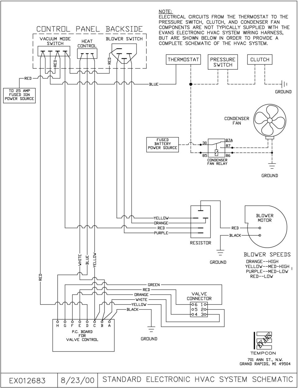
1 EVANS ELECTRONIC TEMPERATURE CONTROL TROUBLESHOOTING GUIDE for systems equipped with electric coolant valve and external PC board. This Troubleshooting Guide covers the electric coolant valve and control system only. For other HVAC system components, diagnosis, and repair, refer to the separate Evans Tempcon publication titled "Dash Heater-Air Conditioner Troubleshooting Guide, Book Two, Rotary Control Panel Systems". NOTE IF TESTING INDICATES A REPLACEMENT VALVE IS NEEDED, IT WILL NEED TO BE REPLACED WITH OUR KIT RV218809, WHICH INCLUDES A NEW STYLE VALVE, WIRING HARNESS, AND INSTRUCTIONS FOR INSTALLATION. THE STYLE OF VALVE COVERED BY THESE INSTRUCTIONS IS NO LONGER AVAILABLE. IF TESTING INDICATES THAT A REPLACEMENT CIRCUIT BOARD IS NEEDED, IT WILL BE AVAILABLE FOR A LIMITED TIME AS OUR SERVICE PACKAGE RV WHEN CURRENT INVENTORY IS GONE, IT TOO WILL NEED TO BE REPLACED BY A KIT RV REPLACEMENT POTENTIOMETERS WILL CONTINUE TO BE AVAILABLE AS OUR SERVICE PACKAGE RV FOR AN INDEFINITE PERIOD. There are three common symptoms of an improperly operating electric coolant control system: No heat in the heat mode (Steps ) Unable to control the temperature in any operating mode (Steps ) Poor cooling, no cooling, or even heat while operating in A/C mode (Steps ) 1.1 Before attempting to troubleshoot, verify that the HVAC system (other than temperature control) is operating correctly. With the vehicle running, test-operate the system and check the following: Blower Motor and 4 operating speeds Mode selector switch and air distribution system A/C system (engine-driven compressor, refrigeration system, etc.). 1.2 With the vehicle running and the A/C system engaged (Blower turned on, Mode selector set to "MAX A/C", Temperature dial rotated to full cool), clamp off the heater inlet hose to see if the A/C system is cooling properly. Test the A/C performance using the EVANS A/C SYSTEM OPERATIONAL CHECK AND PERFORMANCE GUIDELINES. Once this has been determined (and corrected if necessary), remove the clamp from the coolant inlet hose. 1.3 If a significant loss in cooling capacity in the A/C system occurs when the clamp is removed, shut the vehicle off, and carefully follow the step-by-step directions listed below for troubleshooting the coolant control system. If a problem is found, repair/correct the fault before proceeding to the next step. When troubleshooting electric and/or electronic components, care must be taken to prevent component

2 damage while inspecting, using a test meter, light, etc. If questions or concerns arise during the troubleshooting process, contact Evans Tempcon for telephone assistance before proceeding further ( ). 2.1 Remove and inspect the temperature control circuit board, located behind the dashboard. This circuit board is located inside a black plastic housing, which is part of the HVAC wire harness, immediately behind the dash-mounted HVAC control panel. 2.2 The back of the circuit board (smooth side) should be marked with a black letter "B" or "C" stamped in the upper left corner. If a "B" or "C" is not found, replace the circuit board with a new marked board. "B" and "C" boards are physically and electronically identical. The "C" simply designates a supplier labeling change. 2.3 Look for any visual signs of electronic component damage, such as a burned circuit trace or the odor of burnt electronics. If any damage is detected, replace the board. Do Not attempt to solder and/or repair a board. The failure will simply re-occur. 2.4 Check all of the electrical connections in the black plastic housing. Make sure all of the terminals are properly locked in position, in the housing bottom. Check the terminal/wire crimps in this area for secure crimps and positive electrical contact. If damaged terminals or wires are found, replace the wire harness. Refer to attached wiring diagram to verify correct wire color and location in the housing. 2.5 With the engine running, and the HVAC system operating, use a DC voltmeter to verify 12 volt power to the board housing terminals. Terminal "A" is negative (-), and Terminal D is positive (+). With the board removed, volts should be measured across these terminals. If no voltage can be measured across the "A" and "D" terminals, check for a blown fuse, bad ground connection (see Item 7.2), or bad power wire connection. 3.1 The temperature dial on the control panel is a potentiometer control. Unplug the 3-wire connector from the back of this control. Make sure the socket terminals are fully engaged and locked into the wire connector. 3.2 Verify correct wire colors and locations in the connector. Check the 3 pin terminals on the potentiometer for damage. 3.3 Rotate the potentiometer knob to verify smooth operation. The knob should rotate freely from the cool stop (blue), to the warm stop (red). Do not force the knob to rotate past the cool or warm stops. Doing so will cause irreparable damage to the potentiometer control. If the knob can be rotated past the internal stop at the full cool and full heat positions, the potentiometer must be replaced.

3 4.1 Locate the electric coolant valve assembly in the heater base unit compartment, near the Evans Heater-Evaporator unit (on the firewall). The electrical connector is located on the outlet side of the valve. 4.2 Verify positive electrical connections at the coolant valve. Unplug the wire harness connector from the coolant valve. The orange connector cap (containing 6 pin holes) can then be removed from the gray connector body. Loose wires/terminals cannot be locked into place in the connector if the orange connector cap is installed. Use a small screwdriver to pry the orange cap off. With the cap removed, verify that each of the 5 socket terminals is pushed into the gray connector until the retaining ring on the terminal is past the locking tab inside the connector housing. The center tab on the orange cap acts as a secondary lock that holds the socket terminals in place within the gray connector body. Check the socket terminals for damage. Refer to the attached wiring diagram to verify correct wire color and pin location in the gray connector. Re-install the orange locking cap. Inspect the pin terminals on the coolant valve for damage. If any pins (5) in the valve are loose, broken, or missing, replace the valve. 4.3 Verify that the port on the outlet side of the valve is connected to the inlet tube on the heater coil. The coolant supply hose from the engine connects to the inlet side of the valve. Using the attached coolant valve installation diagram, verify that the coolant valve is properly installed in the heater supply hose with the valve ports in a horizontal position as shown in figure 2 of the installation diagram. NOTE: The electric coolant valve is a "directional" valve, and must be correctly installed, or it will not function properly. Coolant valves installed with the coolant flow reversed will leak coolant past the valve gates resulting in poor A/C performance. Valves that have been installed backwards can be reused, but should first be inspected and tested (refer to Step ). 4.4 Verify that the heater supply hose (containing the coolant valve) is actually the hose coming from the supply port on the engine. The supply port is usually on, or near the engine thermostat housing. To positively identify the supply line, remove the valve from the coolant lines and place both ends of the lines into a container to capture escaping fluid. Have an assistant "turn over" the engine while you observe the coolant lines. The line that discharges coolant when the engine is turned over is the supply line for the HVAC system. CAUTION: Removal of the coolant valve should be performed when the engine is cold. Removing the valve from the system when the engine is hot could result in burns and/or serious injury due to extremely hot coolant escaping under pressure. Do not start the engine while the coolant lines are disconnected as the engine will quickly pump the system dry, which could result in damage to the engine.

4 If you have reached this point in the troubleshooting sequence, and no problems or faults have been found, operational testing will be necessary to isolate a faulty component. 5.1 Install a 3/4" O.D. hose splice into the valve location, so the vehicle can be started if necessary. 5.2 Use a wire tie to hang the valve from the heater hose, so the electrical connector can remain plugged in. Position the valve so that you can look into the inlet port of the valve and view the valve gate mechanism operation. 5.3 Turn the vehicle ignition switch to the ignition position; it is not necessary to actually start the vehicle at this time. 5.4 Have a helper slowly rotate the temperature dial from full cool (blue), to full heat (red) while you are watching the white valve gate. As the dial is rotated towards full heat, gate movement should be seen. A small slot will slowly appear, and then a larger opening will appear as the valve fully opens. Then have the helper slowly rotate the temperature dial back to full cool (blue). The valve gate should now move slowly to the closed position. VALVE WITH GATE FULL OPEN VALVE WITH GATE FULL CLOSED NOTE: By nature of the design of the valve, when the coolant valve gate is fully open, half of the valve port opening appears to be blocked. At no time will the valve port appear to be empty. 5.5 If the valve does not operate, disconnect the valve from the wire harness and apply 12 VDC power from an alternate power source directly to the #4 and #6 pins on the valve to determine if the valve gate will open and close. (12 VDC positive to the #4 pin and 12 VDC negative to the #6 pin to close the valve gate VDC positive to the #6 pin and 12 VDC negative to the #4 pin to open the valve gate)

5 5.6 If the valve operates, proceed to Step 5.7. If the valve does not operate, replace the valve and repeat function test (Step ). If the replacement valve does not operate, replace the circuit board and go to Step With the valve gate open, inspect the valve for debris which may cause the valve to not seal properly. Flush the valve with water to remove any visible debris. 5.8 Close the valve gate and test the valve under pressure to determine if the valve is sealing properly. This can be done by securely attaching a water hose to the inlet port on the valve and engaging the source. If a steady stream of water escapes through the outlet port, the valve is defective and must be replaced. 5.9 If the valve operates and seals, replace the circuit board for test purposes. 6.1 Re-test for operation with the new coolant valve and/or circuit board plugged into the harness for test purposes. If coolant valve does not operate, plug a new potentiometer into the harness for test purposes. 7.1 Re-test with the new potentiometer plugged into the harness. If the valve fails to operate, run a complete continuity test of the HVAC electrical system harness to determine if there is a broken or shorted wire, faulty or corroded terminal, etc. 7.2 The HVAC wire harness is supplied with two (2) ground leads crimped into a common terminal. The 16 gauge black wire is the ground lead for the coolant valve circuit. Often, body builders will cut the common terminal off the ground leads and butt splice the leads to the existing chassis ground circuit. The 16 gauge black ground lead for the coolant control circuit should be physically traced back to the grounding source to ensure proper grounding. Check any splices in the leads for continuity. Examine the grounding terminal to determine if it is secure, and the grounding location to determine if it is a good grounding source. 7.3 If a defect is found in the harness, other than any butt spliced connections to the vehicle wiring, the entire harness should be replaced. Any defective butt splices from the HVAC wire harness to the vehicle electrical system should be cut out and replaced. 8.1 Once the faulty component has been identified, the new replacement can be permanently installed. The coolant valve can then be re-installed back into the heater hose. Once everything is buttoned back up, perform an actual function test for warm and cool air with the vehicle running. Test A/C performance using the EVANS A/C SYSTEM OPERATIONAL CHECK AND PERFORMANCE GUIDELINES. NOTE IF TESTING INDICATES A REPLACEMENT VALVE IS NEEDED, IT WILL NEED TO BE REPLACED WITH OUR KIT RV218809, WHICH INCLUDES A NEW STYLE VALVE, WIRING HARNESS, AND INSTRUCTIONS FOR INSTALLATION. THE STYLE OF VALVE COVERED BY THESE INSTRUCTIONS IS NO LONGER AVAILABLE. IF TESTING INDICATES THAT A REPLACEMENT CIRCUIT BOARD IS NEEDED, IT WILL BE AVAILABLE FOR A LIMITED

6 TIME AS OUR SERVICE PACKAGE RV WHEN CURRENT INVENTORY IS GONE, IT TOO WILL NEED TO BE REPLACED BY A KIT RV REPLACEMENT POTENTIOMETERS WILL CONTINUE TO BE AVAILABLE AS OUR SERVICE PACKAGE RV FOR AN INDEFINITE PERIOD.

7
Heater and Air Conditioner, Blend Air System, Troubleshooting 83.06
 A/C Performance Diagnosis Problem Warm Airflow When the Air Conditioner is On, A/C Not Working, or Poor A/C Performance (dash outlet temperature is too high) Problem Warm Airflow When the Air Conditioner
6. Diagnostics for A/C System Malfunction
 6. A: A/C OR SELF-DIAGNOSIS SYSTEMS DO NOT OPERATE TROUBLE SYMPTOM: Set temperature is not indicated on the display, switch LEDs are faulty or switches do not operate. Self-diagnosis system does not operate.
CDS TROUBLESHOOTING SECTION I. VACUUM. 1.0. Weak vacuum at wand. Gauge reads normal (10hg to 14hg)
") CDS TROUBLESHOOTING SECTION I. VACUUM 1.0. Weak vacuum at wand. Gauge reads normal (10hg to 14hg) 1.1. Clogged hoses or wand tube. Disconnect hoses and carefully check for an obstruction. 1.2. Excessive
CDS TROUBLESHOOTING SECTION I. VACUUM 1.0. Weak vacuum at wand. Gauge reads normal (10hg to 14hg) 1.1. Clogged hoses or wand tube. Disconnect hoses and carefully check for an obstruction. 1.2. Excessive
Oil and Coolant Circulating Heating System. Model - OCSM
 Oil and Coolant Circulating Heating System Model - OCSM Installation & Operation Manual 216280-000 REV 2 Identifying Your System The HOTSTART heating system is designed to heat fluids for use in marine
INSTRUCTION MANUAL FOR RECREATIONAL REFRIGERATOR/FREEZER MODEL
 INSTRUCTION MANUAL FOR RECREATIONAL REFRIGERATOR/FREEZER MODEL 15-LITER, 20-LITER, 35-LITER, 45-LITER, 60-LITER & 100-LITER SECTION 1 Basic Operation SECTION 2 Cleaning and Storing SECTION 3 Basic Trouble
Thermo Top - Troubleshooting Tree
 Thermo Top - Troubleshooting Tree 07-15-2002 CAUTION Troubleshooting requires comprehensive knowledge about the structure and theory of operation of the Thermo Top heater. Troubleshooting and repairs may
INSTALLATION INSTRUCTIONS
 INSTALLATION INSTRUCTIONS Electric Vacuum Pump Kit 28146 Thank you for choosing STAINLESS STEEL BRAKES CORPORATION for your braking needs. Pleases take the time to read and carefully follow these instructions
1993 ACCESSORIES & EQUIPMENT Volkswagen Instrument Panels. Volkswagen; EuroVan, Passat
 Article Text Saturday, March 18, 2000 10:33PM ARTICLE BEGINNING 1993 ACCESSORIES & EQUIPMENT Volkswagen Instrument Panels Volkswagen; EuroVan, Passat DESCRIPTION & OPERATION Instrument cluster for most
AUTOMATIC CONTROL HEATING, VENTILATION AND AIR CONDITIONING SYSTEM
 SECTION 7D AUTOMATIC CONTROL HEATING, VENTILATION AND AIR CONDITIONING SYSTEM TABLE OF CONTENTS Description and Operation... 7D- General... 7D- FATC Control... 7D- FATC Input/Output Routing Diagram...
Your safety and the safety of others are very important.
 NATURAL GAS TO PROPANE CONVERSION KIT 090 INSTALLATION INSTRUCTIONS FOR ALTITUDES 0 -,00 FT. ONLY PROPANE CONVERSION KIT SAFETY... INSTALLATION REQUIREMENTS... Tools and Parts... LP Gas Requirements...
SERVICE MANUAL RESIDENTIAL ELECTRIC AND LIGHT DUTY COMMERCIAL ELECTRIC WATER HEATERS. Troubleshooting Guide and Instructions for Service
 RESIDENTIAL ELECTRIC AND LIGHT DUTY COMMERCIAL ELECTRIC WATER HEATERS SERVICE MANUAL Troubleshooting Guide and Instructions for Service (To be performed ONLY by qualified service providers) Models Covered
SERVICE MANUAL 12VDC WALL THERMOSTAT AIR CONDITIONING SYSTEMS ROOFTOP UNITS ONLY
 SERVICE MANUAL 12VDC WALL THERMOSTAT AIR CONDITIONING SYSTEMS ROOFTOP UNITS ONLY! WARNING - SHOCK HAZARD! TO PREVENT THE POSSIBILITY OF SEVERE PERSONAL INJURY, DEATH, OR EQUIPMENT DAMAGE DUE TO ELECTRICAL
ENGINE COOLING SYSTEM
 ENGINE COOLING SYSTEM 1988 Toyota Celica 1987-88 TOYOTA Engine Cooling Systems Celica DESCRIPTION The basic liquid cooling system consists of a radiator, water pump, thermostat, cooling fan, pressure cap,
Section 7. Evaporator thermistor. Under-and-over pressure safety switches. Connections to the ECU
 Automatic Temperature Control Diagnosis and Repair Diagnosis of Automatic A/C Systems The most common automatic A/C system malfunctions tend to be the result of basic air conditioning problems. These problems
Service Guide 12/27/03 TESTING, SERVICE & REPAIR GUIDE (For SH Space Heating Models & RA Water Heating Models)
") TESTING, SERVICE & REPAIR GUIDE (For SH Space Heating Models & RA Water Heating Models) WARNING - HIGH VOLTAGE AC electrical circuits are connected to this heater. Do not attempt any service work on the
TESTING, SERVICE & REPAIR GUIDE (For SH Space Heating Models & RA Water Heating Models) WARNING - HIGH VOLTAGE AC electrical circuits are connected to this heater. Do not attempt any service work on the
PRODUCT: WASHER / WASHER-DRYER COMBO MODEL: AW 120 / AW 122 / AW 125 AWD 120 / AWD 121 / AWD 129
 PRODUCT: WASHER / WASHER-DRYER COMBO MODEL: The information included in this Splendide Repair Manual may change without notice. Please see our web site www.splendide.com/service/docs.html for updates,
SERVICE MANUAL FOR 12 VDC WALL THERMOSTAT AIR CONDITIONING SYSTEMS ROOF TOP UNITS ONLY
 RV Products Division SERVICE MANUAL FOR 12 VDC WALL THERMOSTAT AIR CONDITIONING SYSTEMS ROOF TOP UNITS ONLY Airxcel, Inc. RV Products Division P.O. Box 4020 Wichita, KS 67204 1976A376 (1-11) TABLE OF CONTENTS
specializing in AIR CONDITIONING, PARTS AND SYSTEMS for your classic vehicle PERFECT FIT IN-DASH HEAT/ COOL/ DEFROST 1967-72 CHEVROLET PICKUP
 specializing in AIR CONDITIONING, PARTS AND SYSTEMS for your classic vehicle PERFECT FIT IN-DASH HEAT/ COOL/ DEFROST 1967-72 CHEVROLET PICKUP CONTROL & OPERATING INSTRUCTIONS The controls on your new Perfect
HPC Radiator Fan Control Module with Sensor PN: 102001
 Revised 25.07.15 www.hpcontrols.ca HPC Radiator Fan Control odule with Sensor PN: 102001 The HPC Radiator Fan Controller provides automatic control over one or more electric radiator fan(s). The module
ENGINE COOLING FAN. 1987 Lincoln Mark VII COOLING SYSTEM SERVICING DESCRIPTION MAINTENANCE DRAINING CLEANING FLUSHING
 ENGINE COOLING FAN 1987 Lincoln Mark VII 1987 ENGINE COOLING Ford Motor Co. Engine Cooling Fans Ford; Crown Victoria, Escort, Mustang, Taurus, Tempo & Thunderbird Lincoln; Continental, Mark VII & Town
Left Hand Limit Switch. Housing. Left Hand. Connections. Motor Connector BROWN PURPLE GRAY BLACK DARK BLUE BLACK BROWN BROWN LIGHT BLUE.
 LIGHT BLUE GRAY PURPLE Circuit Breaker Intput Circuit Breaker Output #1 Relay Left Hand Limit Switch Housing Left Hand Motor Connector Right Hand Limit Switch on Radiator Support Right Hand Limit Switch
Service manual. Website: www.andico.com.au CAUTION - BEFORE SERVICING THE UNIT, READ THE SAFETY - PRECAUTIONS IN THIS MANUAL.
 Website: www.andico.com.au Service manual CAUTION - BEFORE SERVICING THE UNIT, READ THE SAFETY - PRECAUTIONS IN THIS MANUAL. - ONLY FOR AUTHORISED SERVICE PERSONNEL. MODELS: MPK1-09CR-QB8 MPK1-12ER-QB6
HVAC SYSTEM (AUTO A/C) (DIAGNOSTICS) AC
 (DIAGNOSTICS) AC") HVAC SYSTEM (AUTO A/C) (DIAGNOSTICS) AC Page. Basic Diagnostic Procedure.... General Description...3 3. Electrical Components Location...6 4. A/C Control Module I/O Signal...8 5. Self-diagnosis...0 6.
HVAC SYSTEM (AUTO A/C) (DIAGNOSTICS) AC Page. Basic Diagnostic Procedure.... General Description...3 3. Electrical Components Location...6 4. A/C Control Module I/O Signal...8 5. Self-diagnosis...0 6.
Class 5 to 7 Truck and Bus Hydraulic Brake System
 Class 5 to 7 Truck and Bus Hydraulic Brake System Diagnostic Guide 1st Edition * 5+0 Important Service tes The information in this publication was current at the time of printing. The information presented
Air conditioning, electrical testing
 just a test. Air conditioning, electrical testing 01-253 Wire and component test using VAG1598 A test box Special tools and equipment VAG 1598 A test box and VAG 1598/11 adapter cable and VAG 1598/12 VAG1526
OASIS SERVICE & TROUBLESHOOTING MANUAL (WITH DM10 OR DM12)
") OASIS SERVICE & TROUBLESHOOTING MANUAL (WITH DM10 OR DM12) Revision 1.0 Page 1 of 50 THE INFORMATION CONTAINED IN THIS DOCUMENT IS THE SOLE PROPERTY OF INTERNATIONAL THERMAL RESEARCH, LTD. ANY REPRODUCTION
OASIS SERVICE & TROUBLESHOOTING MANUAL (WITH DM10 OR DM12) Revision 1.0 Page 1 of 50 THE INFORMATION CONTAINED IN THIS DOCUMENT IS THE SOLE PROPERTY OF INTERNATIONAL THERMAL RESEARCH, LTD. ANY REPRODUCTION
Cooling system components, removing and installing
 Engine BHW Cooling system components, removing and installing Page 1 / 24 19-1 Cooling system components, removing and installing Warning! When doing any repair work, especially in the engine compartment,
Air Conditioning Sign-Off Sheet
 Air Conditioning Sign-Off Sheet Printed Technician Name Address Social Security Number Telephone Number City State Zip Code Install Or Verify The Accuracy Of An Air Conditioner s Installation The candidate
COOL-01, Cooling Fan Operation and Troubleshooting
 COOL-01, Cooling Fan Operation and Troubleshooting Table of Contents Introduction Early 944s With Air Conditioning Cooling Fan Operation On Early 944s With Air Conditioning Testing Fan Relay One Early
NO-FROST CUSTOMER SUPPORT INFORMATION INFORMATION ON THE NO-FROST TECHNOLOGY WHITE GOODS
 INFORMATION INFORMATION ON THE TECHNOLOGY The -Frost refrigerators are different from the other static refrigerators in terms of their operational system. In normal refrigerators, in the freezing section,the
CPL SYSTEMS / GROENEVELD AUTOMATIC GREASING SYSTEM COMPLETE SYSTEM CHECK PNEUMATIC PUMP
 CPL SYSTEMS / GROENEVELD AUTOMATIC GREASING SYSTEM COMPLETE SYSTEM CHECK PNEUMATIC PUMP Feb 5, 2003 1 CPL SYSTEMS / GROENEVELD AUTOMATIC GREASING COMPLETE SYSTEM CHECK - PNEUMATIC PUMP THE SYSTEM DOES
Heating, Ventilation, Air Conditioning and Refrigeration (HVACR)
") Heating, Ventilation, Air Conditioning and Refrigeration (HVACR) I. Demonstrate safety skills in typical HVACR work situations to NATE Core Installer Knowledge Areas for Technician Excellence for Safety
Heating, Ventilation, Air Conditioning and Refrigeration (HVACR) I. Demonstrate safety skills in typical HVACR work situations to NATE Core Installer Knowledge Areas for Technician Excellence for Safety
INSTRUMENT PANEL. 1995 Volvo 850 DESCRIPTION & OPERATION. 1995-96 ACCESSORIES & EQUIPMENT Volvo Instrument Panels
 INSTRUMENT PANEL 1995 Volvo 850 1995-96 ACCESSORIES & EQUIPMENT Volvo Instrument Panels 850 WARNING: When working around steering column and before performing repairs, disconnect and shield battery ground
Not required for most applications Not required for most applications High pressure (12-803 provided) High pressure (12-803 provided)
 High pressure (12-803 provided)") ELECTRIC FUEL PUMPS P/N 12-801-1, 712-801-1, 12-802-1, 712-802-1, 12-815-1, & 712-815-1 FUEL PRESSURE REGULATORS P/N 12-803, 12-501, 12-804, 12-500, & 15812NOS Installation Instructions THESE INSTRUCTIONS
ELECTRIC FUEL PUMPS P/N 12-801-1, 712-801-1, 12-802-1, 712-802-1, 12-815-1, & 712-815-1 FUEL PRESSURE REGULATORS P/N 12-803, 12-501, 12-804, 12-500, & 15812NOS Installation Instructions THESE INSTRUCTIONS
TECHNICAL SERVICE DEPARTMENT Technical Service Bulletin 1-800-432-8373. Tankless Electric (RTE) Troubleshooting
 Troubleshooting") Sequence of Operations 1 Power supply and field wiring block 2 Energy Cut Off (ECO) 3 Water flow plunger and cold inlet 4 Magnetic flow switch 5 Water temperature thermistor 6 Control panel and circuit
Sequence of Operations 1 Power supply and field wiring block 2 Energy Cut Off (ECO) 3 Water flow plunger and cold inlet 4 Magnetic flow switch 5 Water temperature thermistor 6 Control panel and circuit
SERVICE MANUAL FOR 6535 SERIES TWO TON HIGH EFFICIENCY PACKAGED HEAT PUMPS
 SERVICE MANUAL FOR 6535 SERIES TWO TON HIGH EFFICIENCY PACKAGED HEAT PUMPS TABLE OF CONTENTS 1. Warnings...2 2. Accessibility Of Appliance...3 3. Unit Dimensions And Specifications...3 4. Unit Specifications
Companion Service Guide
 Companion Service Guide This Service Guide contains: Troubleshooting Replacement Instructions Contact Information Golden Technologies 401 Bridge Street Old Forge, PA 18518 Toll-free: 800-624-6374 Fax:
12 Volt 30 Amp Digital Solar Charge Controller
 12 Volt 30 Amp Digital Solar Charge Controller User s Manual WARNING Read carefully and understand all INSTRUCTIONS before operating. Failure to follow the safety rules and other basic safety precautions
73 Chevy C10 Ammeter to Volt Gauge Conversion Mark and Michael Olson 2013 Rev 1.0
 73 Chevy C10 Ammeter to Volt Conversion Mark and Michael Olson 2013 Rev 1.0 The ammeter in my son s 73 Chevy C10 did not work, so we decided to convert it to a more modern volt gauge. We made a number
TOYOTA ELECTRONIC TRANSMISSION CHECKS & DIAGNOSIS
 Checks and Adjustments The transmission requires regular maintenance intervals if it is to continue to operate without failure. As we discussed in previous sections, transmission fluid loses certain properties
TROUBLESHOOTING GUIDE
 TROUBLESHOOTING GUIDE LESTRONIC II BATTERY CHARGER FOR MOTIVE POWER BATTERIES PLEASE SAVE THESE IMPORTANT SAFETY AND OPERATING INSTRUCTIONS For correct operation of the equipment, it is important to read
ADDING AN ELECTRIC AUXILIARY FAN TO RADIATOR STACK ON 03 ALPINE COACH
 ADDING AN ELECTRIC AUXILIARY FAN TO RADIATOR STACK ON 03 ALPINE COACH The original design of the 03 Alpine Coaches (and perhaps other years as well) did not include any kind of engine fan engage mechanism
A/C-HEATER SYSTEM - AUTOMATIC
 A/C-HEATER SYSTEM - AUTOMATIC 1995 Volvo 850 1995-96 Auto. A/C-Heater Systems Volvo 850 * PLEASE READ THIS FIRST * WARNING: To avoid injury from accidental air bag deployment, read and carefully follow
Networkfleet 3500 Product Line Installation Guide
 Networkfleet 3500 Product Line Installation Guide Light/Medium Duty (L3500) Heavy Duty (H3500) Universal (U3500) www.networkcar.com/fleet Customer Care: (866) 227-7323 customercare@networkcar.com Table
Electronic Brake Controller Hayes Brake Controller Company ENERGIZE III P/N # 81741B or ENERGIZE XPC P/N #81745 OPERATION MANUAL
 Electronic Brake Controller Hayes Brake Controller Company ENERGIZE III P/N # 81741B or ENERGIZE XPC P/N #81745 OPERATION MANUAL ENERGIZE III is for trailers with 2 or 4 electric brakes and vehicles with
01 12 COOLING SYSTEM COOLING SYSTEM. End of Toc. End Of Sie
 LOCATION INDEX. 1 SERVICE WARNINGS...................... 2 ENGINE COOLANT LEVEL INSPECTION..................... 2 ENGINE COOLANT PROTECTION INSPECTION..................... 2 ENGINE COOLANT REPLACEMENT..
A.Y. McDonald Mfg. Co. Troubleshooting Submersible and Jet Pumps
 A.Y. McDonald Mfg. Co. Troubleshooting Submersible and Jet Pumps Troubleshooting Submersible Pumps Fuse overload or circuit breaker trips when motor is started 1. Incorrect line voltage. Check the line
! WARNING. McDonnell & Miller Installation & Maintenance Instructions MM-217(I) Series 150S and 157S (Snap Switch, All Models except 157S-RB-P)
 Series 150S and 157S (Snap Switch, All Models except 157S-RB-P)") Series 150S and 157S (Snap Switch, All Models except 157S-RB-P) Low Water Cut-Off/Pump Controllers For Steam Boilers and Other Level Control Applications McDonnell & Miller Installation & Maintenance Instructions
Series 150S and 157S (Snap Switch, All Models except 157S-RB-P) Low Water Cut-Off/Pump Controllers For Steam Boilers and Other Level Control Applications McDonnell & Miller Installation & Maintenance Instructions
INSTALL INSTRUCTIONS KK-C-HVAC-1 HVAC UNIT 2003-2014 CHEVROLET/GMC VANS FOR
 INSTALL INSTRUCTIONS KK-C-HVAC-1 HVAC UNIT 2003-2014 CHEVROLET/GMC VANS FOR (For NEW 2007 ALL WHITE KWIK-KITS ONLY) Warning do not attempt to install A/C units unless you are experienced with servicing
THERMOSTATIC MIXING VALVE TRIM K-T9493, K-T9494
 THERMOSTATIC MIXING VALVE TRIM K-T9493, K-T9494 1. BEFORE YOU BEGIN IMPORTANT INSTRUCTIONS READ AND SAVE FOR THE CONSUMER WARNING: Risk of scalding or other severe injury. Before completing installation,
SERVICE TIPS. Dometic REFRIGERATORS. Models. OS1927 4/96 Copyright 1996 The Dometic Corporation
 SERVICE TIPS Dometic REFRIGERATORS Models RM2612 RM2652 RM2812 RM2852 OS1927 4/96 Copyright 1996 The Dometic Corporation THE MOST COMMON SYSTEM PROBLEMS ASSOCIATED WITH THE RM2612, RM2812, RM2652, RM2852
ENERGY SMART TROUBLESHOOTING GUIDE TABLE OF CONTENTS:
 ENERGY SMART TROUBLESHOOTING GUIDE TABLE OF CONTENTS: COMPONENTS/BOARD LAYOUT... 2 HOT WATER... 3 1 FLASH (GREEN DIAGSTIC LIGHT)... 4 2 FLASHES (GREEN DIAGSTIC LIGHT)... 5 3 FLASHES (GREEN DIAGSTIC LIGHT)...
1970-72 Chevelle. 1970-72 Chevelle. (500645) Gauge Cluster Kit Installation Instructions. (500645) Gauge Cluster Kit Installation Instructions
 Gauge Cluster Kit Installation Instructions. (500645) Gauge Cluster Kit Installation Instructions") 1970-72 Chevelle (500645) Gauge Cluster Kit Installation Instructions 1970-72 Chevelle (500645) Gauge Cluster Kit Installation Instructions STEP 1: There are 4 small gauges. This is a photo of the bare
1970-72 Chevelle (500645) Gauge Cluster Kit Installation Instructions 1970-72 Chevelle (500645) Gauge Cluster Kit Installation Instructions STEP 1: There are 4 small gauges. This is a photo of the bare
Cooling system components, servicing
 19-1 Cooling system components, servicing WARNING! The cooling system is pressurized when the engine is warm. When opening the expansion tank, wear gloves and other appropriate protection, cover the cap
Essential Electrical Concepts
 Essential Electrical Concepts Introduction Modern vehicles incorporate many electrical and electronic components and systems: Audio Lights Navigation Engine control Transmission control Braking and traction
Norcold Repair Guide Models 442, 443, 452, 453, 462, 463, 482, 483
 Norcold Repair Guide Models 442, 443, 452, 453, 462, 463, 482, 483 Section 3 Table of Contents Page 3-2 General Information and Specification 3-3 Information About Electrical Connections 3-3 Description
HVAC-02, Air Conditioning Troubleshooting and Repair
 HVAC-02, Air Conditioning Troubleshooting and Introduction Since I'm constantly receiving questions on 944 air conditioning systems, I figured it's time to come up with come helpful troubleshooting tips.
Section 7 Adjustment, Repair and Replacement
 Section 7 Adjustment, Repair, and Replacement Page 7-1 Section 7 Adjustment, Repair and Replacement Section Contents Page Overview...7-5 Belts Belt Guard Removal/Installation...7-7 Belt Removal/Installation...7-11
Volkswagen B3 Passat General-Engine 4 CYL. 19 Engine - Cooling System (Page GR-19)
") 19 Engine - Cooling System (Page GR-19) Cooling system draining and filling general information Body components, layout Engine components, layout Radiator fan run-on checking Recommended mixture ratios
19 Engine - Cooling System (Page GR-19) Cooling system draining and filling general information Body components, layout Engine components, layout Radiator fan run-on checking Recommended mixture ratios
Automatic taper of charge rate for superior battery life through good equalization of cells and low water use rate.
 *00151* FEATURES Automatic taper of charge rate for superior battery life through good equalization of cells and low water use rate. Silicon diodes with inherent surge protection operated at a conservative
OWNER S MANUAL FORCE 10 MARINE COMPANY 23080 HAMILTON ROAD RICHMOND, BC CANADA V6V 1C9 TEL: (604) 522-0233 FAX: (604) 522-9608
 522-0233 FAX: (604) 522-9608") Electric Water Heater OWNER S MANUAL FORCE 10 MARINE COMPANY 23080 HAMILTON ROAD RICHMOND, BC CANADA V6V 1C9 TEL: (604) 522-0233 FAX: (604) 522-9608 If your water Heater is Damaged or you have questions
Electric Water Heater OWNER S MANUAL FORCE 10 MARINE COMPANY 23080 HAMILTON ROAD RICHMOND, BC CANADA V6V 1C9 TEL: (604) 522-0233 FAX: (604) 522-9608 If your water Heater is Damaged or you have questions
Technical Guide 08/15/14
 Technical Guide 08/15/14 1 Table of Contents Contact information.3 Identifying your system..4-8 Model Number Serial number location Parts of your fuel system..9-14 Fuel pump diagram Wire harness schematics
http://waterheatertimer.org/how-to-troubleshoot-gas-water-heater.html
 http://waterheatertimer.org/how-to-troubleshoot-gas-water-heater.html TECHNICAL SERVICE DEPARTMENT Effective October 2007, we transitioned to the White Rodgers (Intelli-Vent TM )Thermostat Control for
The Charging System. Section 5. Charging System. Charging System. The charging system has two essential functions:
 The Charging System Charging System The charging system has two essential functions: Generate electrical power to run the vehicle s electrical systems Generate current to recharge the vehicle s battery
How To Fix A Car With A Carbide Engine
 Section 12 Adjustment, Repair, and Replacement Page 12-1 Section 12 Adjustment, Repair and Replacement Section Contents Page Overview...12-5 Belts Belt Guard Removal/Installation...12-7 Belt Removal/Installation...12-11
PUSH BUTTON START INSTALLATION MANUAL
 PUSH BUTTON START INSTALLATION MANUAL ALTHOUGH THIS PRODUCT HAS BEEN THOROUGHLY TESTED KPIERSON TECHNOLOGIES ASSUMES NO RESPONSIBILITY FOR ANY DAMAGE THAT MAY RESULT BY THE INSTALLATION OF THIS PRODUCT.
USER INSTRUCTIONS FOR GET PORTABLE 12k BTU AIR CONDITIONER MODEL No. GPACU12HR
 USER INSTRUCTIONS FOR GET PORTABLE 12k BTU AIR CONDITIONER MODEL No. GPACU12HR CONTENTS Introduction Safety Notes Identification of parts Installation instructions Operation instructions Maintenance Troubleshooting
1978-83 Malibu 1978-87 Monte Carlo 1978-87 El Camino
 Important facts about this kit. 1. The dash panel used in this picture is used by permission of Covan's Classic. 2. This kit requires some modification to your original under dash wiring harness. It is
DANGER DANGER. General Information. Safety Is Your Responsibility. Ordering Parts. Contact Information
 Safety Safety Is Your Responsibility DANGER To avoid personal injury or death, carefully read and understand all instructions pertaining to the Anthony Liftgates product. Do not attempt to install, operate,
CARING FOR YOUR WATER HEATER
 http://waterheatertimer.org/troubleshoot-rheem-tankless-water-heater.html Water Heater Inspections CARING FOR YOUR WATER HEATER Venting System (Direct Vent Only) The venting system should be inspected
i ChatterBox! Motorcycle Security
 i Before you Start the Installation * Please read this manual to become familiar with the requirements necessary to complete the installation. * Use a high quality multi-meter to test all wires before
DRIVEABILITY MALFUNCTION INDICATOR LAMP
 DRIVEABILITY MALFUNCTION INDICATOR LAMP Article No. (MIL) ILLUMINATED WITH DIAGNOSTIC TROUBLE 01-7-8 CODES (DTCS) P0455, P0456, P0457, P0442, P1442, P1443, P1450 OR P1455 ROTUNDA VACUTEC 522 LEAK DETECTOR
ELECTRONIC THERMOSTAT AND THERMOMETER With SPEED CONTROL
 148 OLD CONCORD TURNPIKE, BARRINGTON NH 03825 USA TEL (603) 868-5720 FAX (603) 868-1040 1-800-435-6708 E-Mail:sales@seafrost.com www.seafrost.com ELECTRONIC THERMOSTAT AND THERMOMETER With SPEED CONTROL
FAN-PWM-V3. Instructions
 FAN-PWM-V3 Instructions HOLDER AMP BOOKLET YELLOW RING CONNECTORS (2) INSTRUCTION INSTRUCTION BOOKLETBOOKLET ITEMS INCLUDED IN KIT INSTRUCTION ITEMS INCLUDED IN KIT ITEMS INCLUDED IN KIT INSTRUCTION BOOKLET
Digi-Motor Installation Guide
 Digi-Motor Installation Guide Installation Video...located at marsdelivers.com Digi-Motor Installation Guide Digi-Motor For technical assistance with your Azure Digi-Motor, call the MARS technical support
A4 Air Conditioning Control Circuit Troubleshooting Rev 7, 6/18/2009
 A4 Air Conditioning Control Circuit Troubleshooting Rev 7, 6/18/2009 ** This guide is for Manual Air Conditioning (as opposed to Climatronic A/C or Climatic A/C), with two 2-speed fans on Volkswagen A4's
Battery Chargers. Revised 8/00 Form Number 56041170 FORM NO. 56041170 / BATTERY CHARGER SERVICE MANUAL / PARTS LIST - 45
 Battery Chargers SERVICE MANUAL / PARTS LIST AUTOMATIC Advance MODELS 0980, 098, 797, 8809, 90, 880, 880, 099, 08,, 09788, 098, 7, 097, 70, 790, 889 Lester MODELS 007,, 8, 8, 89, 80, 9, 00, 00, 008 MANUAL
 0150506194 C Limited 2nd through 5th Year Functional Parts Warranty During the 2nd through 5th year,haier will provide functional parts which prove to be defective due to workmanship
A&A CORVETTE PERFORMANCE C6 BOOST & FUEL GAUGE INSTALLATION INSTRUCTIONS
 A&A CORVETTE PERFORMANCE C6 BOOST & FUEL GAUGE INSTALLATION INSTRUCTIONS 1. Check your gauges before you take them out of the packaging to make sure they are at 0 (zero) psi for both boost and fuel pressure.
Rain+Birdt. Simple To Set Timer (SST) Setup & Operation Instructions. English. 1-800- RAIN BIRD (800-724-6247) or visit www.rainbird.
 Setup & Operation Instructions. English. 1-800- RAIN BIRD (800-724-6247) or visit www.rainbird.") Rain+Birdt Simple To Set r (SST) Setup & Operation Instructions English Installation...2 Tools and Supplies Needed...2 Step 1. Mount r...2 Step 2. Connect Power...2 Indoor r...2 Outdoor r...2 Step 3. Connect
Rain+Birdt Simple To Set r (SST) Setup & Operation Instructions English Installation...2 Tools and Supplies Needed...2 Step 1. Mount r...2 Step 2. Connect Power...2 Indoor r...2 Outdoor r...2 Step 3. Connect
WIRE, TERMINAL AND CONNECTOR REPAIR CONDUCTORS
 CONDUCTORS Conductors are needed to complete the path for electrical current to flow from the power source to the working devices and back to the power source. Special wiring is needed for battery cables
R02GA. July 31, 2002. Dear Blue Bird Owner:
 R02GA July 31, 2002 Dear Blue Bird Owner: This notice is sent to you in accordance with the requirements of the National Traffic and Motor Vehicle Safety Act. Blue Bird Body Company has determined that
Installation and Troubleshooting Instructions for Electric Tankless Residential Water Heaters.
 Model Number: Serial Number: Information Manual Installation and Troubleshooting Instructions for Electric Tankless Residential Water Heaters. ATTENTION: IF YOU ARE NOT A LICENSED PLUMBER OR A LICENSED
Cooling system components, removing and installing
 Page 1 of 34 19-1 Cooling system components, removing and installing WARNING! The cooling system is pressurized when the engine is warm. When opening the expansion tank, wear gloves and other appropriate
Windshield Wiper Motors
 Windshield Wiper Motors Originally posted by Dan Masters, danmas@aol.com Also see http://www.advanceautowire.com/ WIPER OPERATION: There are three major components to a wiper motor: Motor Rotary to linear
Cooling system components, removing and installing
 Volkswagen Touareg 3.2 - Cooling system components, removing and installing Page 1 / 24 19-1 Cooling system components, removing and installing Warning! Hot steam may escape when opening expansion tank.
Name of Equipment Silver King Model SKMCD1P/C1. This equipment chapter is to be inserted in the appropriate section of the Equipment Manual.
 Name of Equipment Silver King Model SKMCD1P/C1 This equipment chapter is to be inserted in the appropriate section of the Equipment Manual. Manufactured exclusively for McDonald s By Silver King Refrigeration,
UNIVERSAL LUMBAR INSTALLATION INSTRUCTIONS
 UNIVERSAL LUMBAR INSTALLATION INSTRUCTIONS CONTENTS Parts List... 2 Parts Diagram... 2 Helpful Hints... 3 Installation... 4 Operation and Troubleshooting Guide... 6 Warranty Information... 8 Form #3132,
Trouble Shooting BD & TW Compressor Systems 12 and 24 Volt
 Trouble Shooting BD & TW Compressor Systems 12 and 24 Volt Determine the Model. The data plate is on the left end near the wiring entrance. BD - BD air* TW - Tradewinds air** BDAW - BD air/water TWAW -
Ultraviolet Germicidal Lamps Owner s Manual MODELS 1910 & 1930
 Ultraviolet Germicidal Lamps Owner s Manual MODELS 1910 & 1930 WARNING Ultraviolet light is harmful to eyes and skin. Never look at light produced by this lamp. Unplug lamp before servicing. Electrical
DESCRIPTION. DTC P0351 Ignition Coil "A" Primary / Secondary Circuit. DTC P0352 Ignition Coil "B" Primary / Secondary Circuit
 1 of 10 6/4/2012 10:38 PM Last Modified: 3-27-2012 6.4 C From: 201203 Model Year: 2013 Model: FR-S Doc ID: RM000000XH40PUX Title: FA20 ENGINE CONTROL: SFI SYSTEM: P0351-P0354: Ignition Coil "A" Primary
Installation Instructions 4508 4508S
 SYMPHONY Spread Lavatory Faucet with Speed Connect Drain Congratulations on purchasing your American Standard faucet with Speed Connect drain, a feature found only on American Standard faucets. Speed Connect
MODEL 300505 INSTALLATION INSTRUCTIONS
 WWW.BURCAM.COM 2190 Boul. Dagenais West TEL: 514.337.4415 LAVAL (QUEBEC) FAX: 514.337.4029 CANADA H7L 5X9 info@burcam.com Your pump has been carefully packaged at the factory to prevent damage during shipping.
http://waterheatertimer.org/troubleshoot-rheem-tankless-water-heater.html
 http://waterheatertimer.org/troubleshoot-rheem-tankless-water-heater.html TECHNICAL SERVICE DEPARTMENT Removal, Cleaning, & Reinstallation of the Burner Assembly For models 74 & GT199 Required tools -
Installation and Operation Guide for PD4100 Series Power Control Centers
 Installation and Operation Guide for PD4100 Series Power Control Centers Extended warranties are available for purchase at www.progressivedyn.com Member Thank you for selecting Progressive Dynamics as
Customized Assessment Blueprint
 Customized Assessment Blueprint HVAC Installer Basic - Test Codes: 7906 and 7796 Measuring What Matters Competencies and Skills Tested in this Assessment: HVAC Theory Heat Theory and Refrigeration HVAC
Transport Air Conditioning TRANSPORT AIR CONDITIONING OPERATOR S MANUAL. for SPLIT SYSTEM. Bus Air Conditioning Units.
 R Transport Air Conditioning TRANSPORT AIR CONDITIONING OPERATOR S MANUAL for SPLIT SYSTEM Bus Air Conditioning Units T--326 Rev -- OPERATOR S MANUAL BUS AIR CONDITIONING UNITS GEN IV & GEN V CONTENTS
USER MANUAL WARNING! CONTENTS MODEL 1 SPECIFICATIONS READ ALL INSTRUCTIONS BEFORE PROCEEDING. Non-Programmable Single Stage Heat/Cool Thermostat
 Builder MODEL 1010 Series Non-Programmable Single Stage Heat/Cool Thermostat USER MANUAL Compatible with low voltage single stage gas, oil or electric heating or cooling systems, including single stage
Training Syllabus to Instruct/Prepare for the ASE Transit Bus HVAC Test
 APTA STANDARDS DEVELOPMENT PROGRAM RECOMMENDED PRACTICE American Public Transportation Association 1666 K Street, NW, Washington, DC, 20006-1215 APTA BTS-BMT-RP-001-10 Approved October, 2010 APTA Bus Maintenance