Hydraulic Compressor Module
|
|
|
- Rachel Elliott
- 8 years ago
- Views:
Transcription
1 Down Force Circuit 3/8 PTC Ports Hydraulic Compressor Module (Top 2 Shown With Plugs) Lift Force Circuit Tank Drain (Pull Cord) 10 Gallon Air Tank Down Pressure Gauge Lift Pressure Gauge 3/8 Quick-Connect Female Hydraulic Motor Tank Pressure Gauge Enclosure Lid Latch Hydraulic Inlet Hydraulic Outlet Air Compressor

2 Sub-Assembly Manifold Hydraulic Motor Check Drive Belt Tensioner Air-In from Tank Air Line Out to Tank Air Force Module (AFM) Tank Air Filter Thermistor Compressor Temperature Flow Control Valve K-12 Air Compressor Hydraulic Hose Return Line Hydraulic Hose Positive Line Diagnostic Test Plug Hydraulic Manifold ON/OFF Valve Relief Valve Compressor Air Filter with Pre-Filter Control Harness Air Force

3 Tank Pressure Sensor Down System Pressure Sensor Down System Inlet Check Valve Auxiliary Air Input Down Vent Control Valve Down Increase Control Valve Lift Increase Control Valve Exhaust Vent Lift System Pressure Sensor Lift Vent Control Valve Lift System Auxiliary Air Input Relief Valve Accessory Air Chuck

4 Connecting Power to the Compressor For Hydraulic Compressor Modules, the compressor is belt driven from an hydraulic motor within the enclosure. Hydraulic Hose Kit * ^ Part Number Part Name Description Note TEE -8 STOR TEE A ELBOW -8 STOR X -6 JIC 90 DEG ELBOW B ADAPTER -8 STOR X -6 JIC C HOSE AS ENCLOSURE TO TRACTOR D REDUCER -8 JIC X '6 JIC REDUCER E ELBOW -6 JIC 90 DEG SWIVEL ELBOW E TEE -8 JIC RUN TEE E COUPLER PIONEER COUPLING - POPPET STYLE C * THIS KIT IS INTENDED FOR INSTALLING IN CCS CIRCUIT OF DEERE PLANTERS + THIS KIT IS INTENDED FOR INSTALLING IN CCS CIRCUIT OF DB PLANTERS ^ THIS KIT INTENDED WHEN USING A SEPARATE DEDICATED CIRCUIT FOR AIRFORCE COMPRESSOR Note: A B C D E E E C Install between Pioneer quick couplers and existing hoses of planter 2 get installed at manifold on enclosure, 2 install into Tee's at hydraulic coupler Install at end of hose which plugs into tractor Enclosure to Tractor, approx. 10' lengths Install at bulkhead fittings on planter hitch

5 Standard Installation: Compressor Module mounted on Draft Bar at the front of the planter Plumbing to CCS Circuit / Planter Raise-Lower Circuit Hydraulic Connections will be made to the front of the compressor module to the gold colored manifold in the lower left corner. Port A will be the oil inlet port - requires oil supplied to it. Port B will be the oil return port - oil is plumbed to return to the tractor. The lower left and top right ports are construction ports and will remain plugged. Port A Oil Inlet Port B Oil Return Construction Ports; these remain plugged Locate the hydraulic circuit on the planter marked Frame or Lift. This should be the largest set of hoses leading to the planter and is the circuit responsible for raising and lowering the planter. Most planter manufacturers label these hoses with a colored cable in the context of Raising the planter; such as Pressure and Return. The compressor module will be plumbed in reverse of this condition; or requires flow when Lowering the planter. Connect port A to the hose marked Return Connect port B to the hose marked Pressure The image at right shows this connection made to the rear of the fixed plate on the front of John Deere DB series planters. Verify on your planter which hose is Pressure and which is Return.

6 For non-db series planters, this connection should be made just behind the Pioneer couplers that plug into the tractor remotes. The images below show examples of this connection. -8 STOR TEE -8 STOR X -6 JIC 90DEG ELBOW Hydraulic Hose Assembly Non-Standard Installation: Compressor Module installed at rear of planter Plumbing to CCS Circuit / Planter Raise-Lower Circuit Hydraulic Connections will be made to the front of the compressor module to the gold colored manifold in the lower left corner. Port A will be the oil inlet port - requires oil supplied to it. Port B will be the oil return port - oil is plumbed to return to the tractor. The lower left and top right ports are construction ports and will remain plugged. Port A Oil Inlet Port B Oil Return Construction Ports; these remain plugged

7 When installing the Compressor Module at the rear of the planter (most often on the tongue of the planter in front of the CCS blower or Refuge tank) hydraulic oil will need to be supplied from the planters main hydraulic line or manifold. This is usually located at the center of the planter, under the CCS tanks or catwalks. You will need to locate the Frame/Planter Raise and Lower circuit lines or trace backwards from the CCS blower motor to the manifold to find the appropriate ports to tie into. We strongly discourage getting the oil supply for the Compressor Module directly from the CCS blower hoses, This will add restriction to the line and could negatively affect CCS blower operation if done incorrectly. Once the correct ports/hoses have been identified, you can T into the lines just as with a standard installation. The required fittings for this installation may vary, but the most common fittings required are listed below. These may be obtained locally or through Precision Planting using the part numbers referenced. Quantity Part Number Description JIC TEE JIC X -6 JIC REDUCER SAE X -6 JIC ELBOW HYD HOSE (approx. 100 long) JIC Straight Coupling (for use with hose only) Quick Checks for Hydraulic Compressors Common reasons Hydraulic Compressor will not operate: Planter must be lowered Hydraulic Circuit must be connected and engaged Tank Pressure is within 25psi of target (ie; target tank pressure is 150psi, actual tank pressure must be <125psi before compressor will engage) Verify that circuit is plumbed correctly: the hose into Port A should visibly pulse when the circuit is energized. AirForce System must be Enabled within the 20/20 SeedSense monitor. To test the system, the AirForce system must be in Manual mode (selected on the monitor through the AirForce Control Center). Automatic modes require the planter to be lowered, the hydraulic circuit energized, moving forward, and to be planting.


8 Nominal Size Dash Size Nominal Thread Chart for identifying size and type of common hydraulic system threads NPTF SAE ORB JIC 37 Deg FLARE ORFS Male Thd OD Female Thd ID Nominal Thread Male Thd OD Female Thd ID Nominal Thread Male Thd OD Female Thd ID Nominal Thread 1/8 02 1/ / / N/A 3/16 03 N/A 3/ / N/A 1/4 04 1/ / / / /16 05 N/A 1/ / N/A 3/8 06 3/ / / / /2 08 1/ / / / /8 10 N/A 7/ / /4 12 3/ / / / /8 14 N/A 1 13/ / N/A / / / / / /4-11 1/ / / / / /2-11 1/ / / / / / N/A These four different types of threads can often be mismatched due to common threads but will not seal properly and may result in dangerous leaks. When ordering replacement fittings, verify which style and speak in terms of -Dash size to prevent confusion. NPTF is easily recognizable and looks like regular pipe threads. It is not recommended for hydraulic systems but does exist on some ag equipment. SAE ORB is a common and reliable thread type used in ports on valves, pumps, and cylinders. It utilizes an O-ring for sealing and the port can be recognized by a spot face and nice chamfer at the top of the port. JIC 37 Deg FLARE is the common thread type used on hoses. The fitting has a taper on the end and the coupling of the hose has an internal taper. The taper is the sealing surface. ORFS (O-Ring Face Seal) is a newer style of fitting used on hoses. It uses an O-ring at the face of the seal instead of relying on a metal-to-metal seal on the taper. Male Thd OD Female Thd ID

9 Hydraulic Compressor Module


10


11


12

13 Item Quantity Part Number Part Name Description Bolt 1/4-20 X 5/8" GRD5 Zinc Bolt 1/4-20 X 1 GRD5 Zinc Bolt 1/4X1.75 HCS Bolt 5/16X1.5 GRD5 Zinc Bolt 3/8-16X2 GRD5 Zinc Bolt 3/8-16 X 2 HHCS GRD5 Zinc Bolt 3/8-16 X 3.5 HCS Bolt 1/4-28 X 5/8 LG GRD5 ZN Screw X 1/2 Pan Phillips m/s steel Zinc Washer 5/16 USS Flat Washer 3/8 USS Flat ZN Lock Washer Washer #10 External Tooth Lock Washer 1/4" External Tooth Lock Nut Zinc Hex Nut Nut 1/4-20 GRD5 Zinc Hex Nut Nut 3/8-16 Z5 Hex Nut Nut 3/8-16 Square STL Zinc Cable Tie 6" UV Black Cable Tie 30# Tensile Screw 6-32 X 5/16" Pan Phillips T/F Zinc Manifold Group Pneumatic Down and Lift Air Tank 10 Gallon Air Tank Assembly Control Module AirForce Module Sensor Thermistor, Compressor Temperature Sensor Valve Relief Valve (175psi) Drain Cock Tank Condensate Drain Fitting 1/4"NPT X 1/4" PTC Straight Male Fitting Fitting 1/4"NPT X 3/8" PTC Straight Male Fitting Fitting 1/4"NPT Brass Plug Hinge Enclosure Lid Hinge Bumper Rubber Enclosure Lid Filter Compressor Pre-Filter Compressor Hydraulic Compressor Assembly Service Kit Service Kit Assembly Latch Enclosure Lid Latch Manifold Hydraulic Manifold Cover Hydraulic Enclosure Enclosure Hydraulic Enclosure Assembly

14 Item Quantity Part Number Part Name Description Bolt 1/4-20 X 5/8" GRD5 Zinc Guard Hydraulic Assembly Fitting 1/8"PTC 90degree Elbow Fitting 3/8"PTC 90degree Elbow Rivet 7/32" Tubular Rivet Fitting 1/4" NPT Coupler - Quick Disconnect Fitting 3/4" NPT Plug Chuck Air Chuck Hose Assembly Hydraulic Motor, Hose Assembly Motor Hydraulic Motor V Belt Drive Belt (A-57) Harness Hydraulic Control Harness Hose Assembly Accessory Hose Idler Flat Idler Filter Tank Filter (Hydraulic) Sheave Adapter Compressor Outlet Adapter -8 SAEBoss X -6 JIC Straight Adapter Plug -8 JIC Plug Hose Assembly Hydraulic Compressor Bushing 3/4"NPT X 3/8"NPT Valve Unloading Check Valve Adapter 3/8"NPT X 3/8" JIC Grommet Wire Harness Grommet Fitting -6SAE Boss X -6JIC 45degree Elbow Tubing 3/8" Tank to Filter Tubing 3/8" Filter to Manifold Tubing 1/8" Sensor to Guage (Tank & Lift) Tubing 1/8" Sensor to Guage (Down) Oil (gal) Compressor 20WT Oil (gal) Hydraullic 10WT Gauge 160 psi Panel Mount Clamp Push Mount 2-Stage Lock Filter Compressor Inlet Lanyard Enclosure Lid Label "Drain Condensation" Label Guages' Label Tank and Enclosure' Label Hydraulic Enclosure AirForce Label Serial Number
 53 1 726383 Sheave 54 1 726387 Adapter Compressor Outlet 55 2 726404 Adapter -8 SAEBoss X -6 JIC Straight Adapter 56 2 726417 Plug")

15 Manifold Sub-Assembly
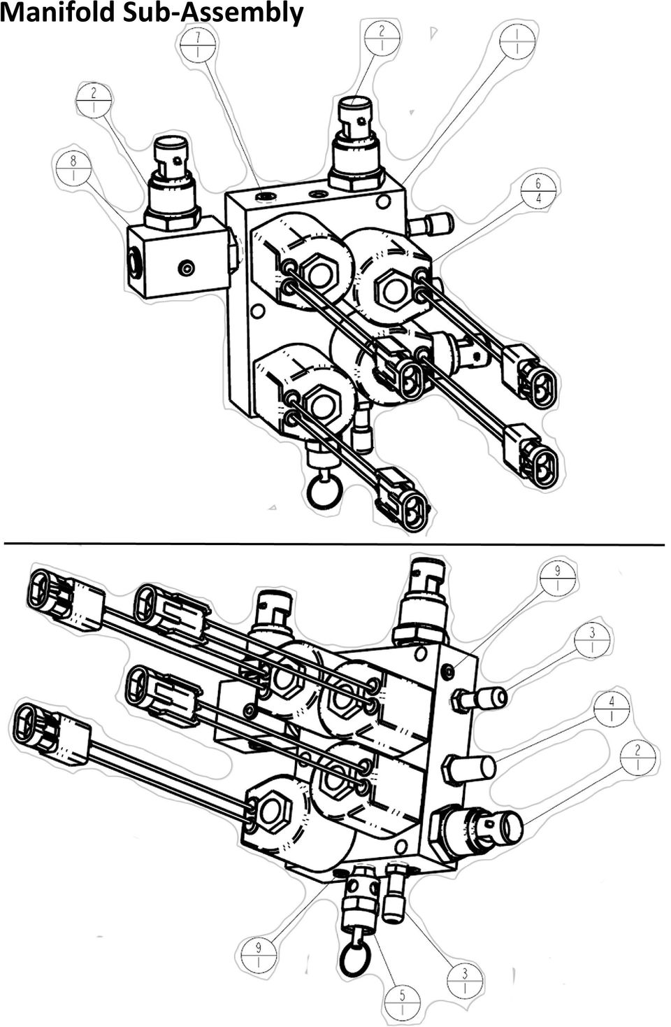

16 Item Quantity Part Number Part Name Description Machined Cast Aluminum Manifold Assembly Manifold Block Sensor Pressure Valve Schrader Vent Exhaust Vent Valve Relief Valve Valve Assembly Fitting 1/8"NPT Plug Valve Assembly Inlet Check Fitting 1/8" PTC Cartridge Fitting 3/8" PTC Cartridge Cap Red 3/8 PTC

17 Compressor Sub-Assembly

18

19 Hydraulic Compressor Maintenance Guidelines LUBRICATION The compressor has been filled with 20 WT oil at the factory. Before beginning operation, check that the oil level is still correct. The oil sight gauge should be filled ¾ full. You should be able to see a small bubble at the top of the sight gauge. Be sure not to fill above the indicated level. DO NOT USE A DETERGENT OIL! All models are splash lubricated by means of dippers on the connecting rods. The pump must be operated in a level position for proper lubrication. Oil Capacity 15 oz ( <½ quart ) Oil type Deg F ambient 20 WT Non-Detergent 56 Deg F & above 30 WT Non-Detergent Always check when cool BELTS Belt tension should be adjusted to allow 3/8 to ½ deflection with normal thumb pressure. GUARDS Always ensure that guard is in place before operating the compressor. FILTER Monitor the pre-cleaner for blockage. A torn or damaged pre-cleaner should be replaced. In normal use the precleaner will prevent the paper element filter from becoming plugged even in dusty conditions. MAINTENANCE SCHEDULE DAILY Drain condensation from water separator and tank. Check oil level and fill as needed. (Change compressor oil after first 50 compressor hours) SEASONALLY / 200 COMPRESSOR HOURS Change compressor oil. Examine compressor inlet filter and change if dirty. Check drive belt and adjust if necessary. Check for air and oil leaks and correct.
 Oil type 32-55 Deg F ambient 20 WT Non-Detergent 56 Deg F & above 30 WT Non-Detergent Always check when cool BELTS Belt tension should be adjusted to allow 3/8 to ½")
 C7, N2 3 Pink RS 485(-) C6, N3 4 Red 12 Volt Power B8, DB, EB, FB, JA, KA, MB, N4 726367 Connector B 12 Pin Deutsch Gray Plug AFM PIN NO.")
20 Connector A 4 Pin AMP Receptacle From Display PIN NO. COLOR FUNCTION TO 1 Black Ground C4, JB, N1 2 Brown RS 485 (+) C7, N2 3 Pink RS 485(-) C6, N3 4 Red 12 Volt Power B8, DB, EB, FB, JA, KA, MB, N Connector B 12 Pin Deutsch Gray Plug AFM PIN NO. COLOR FUNCTION TO 1 Green Compressor Temp (-) L2 2 Not used 3 Orange Compressor Temp (+) L1 4 White Down PSI Signal HC 5 Blue Lift PSI Signal GC 6 Red Analog (+) 5 Volt GB, HB, IB 7 Not Used 8 Red 12 Volt Power A4, DB, EB, FB, JA, KA, MB, N4 9 Green Sensor Ground GA, HA, IA 10 Purple Tank PSI Signal IC 11 Not Used 12 Not Used Connector H Packard Plug Down Pressure Sensor PIN NO. COLOR FUNCTION FROM A Green Sensor Ground C9, GA, IA B Red Analog (+) 5 Volt B6, GB, IB C White Down PSI Signal B Connector I Packard Plug Tank Pressure Sensor PIN NO. COLOR FUNCTION From A Green Sensor Ground C9, GA, HA B Red Analog (+) 5 Volt B6, GB, HB C Purple Tank PSI Signal B10

21 Connector D 2 Pin Weather Pack Female Lift Vent Solenoid PIN NO. COLOR FUNCTION FROM A White Lift Vent (LV) C9 B Red Lift Vent (LV) Power A4, B8, EB, FB, JA, KA, MB, N Connector E 2 Pin Weather Pack Female Lift Increase Solenoid PIN NO. COLOR FUNCTION FROM A White Lift Increase (LI) C10 B Red Lift Increase (LI) Power A4, B8, DB, FB, JA, KA, MB, N Connector F 2 Pin Weather Pack Female Down Vent Solenoid PIN NO. COLOR FUNCTION FROM A White Down Vent (DV) C5 B Red Down Vent (DV) Power A4, B8, DB, EB, JA, KA, MB, N Connector G Packard Plug Lift Pressure Sensor PIN NO. COLOR FUNCTION FROM A Green Sensor Ground. C9, HA, IA B Red Analog (+) 5 Volt B6, HB, IB C Blue Lift PSI Connector Signal C B5 12 Pin Deutsch Connector J 2 Pin Weather Pack Female Diagnostic Connector 12 Volt PIN NO. COLOR FUNCTION FROM A Red 12 Volt Power A4, B8, DB, E8, FB, KA, MB, N4 B Black Ground A1, C4, N Connector K 2 Pin Weather Pack Female Compressor Relay PIN NO. COLOR FUNCTION FROM A Red Compressor Relay +12 A4, B8, DB, EB, FB, JA, MB, N4 B Black Compressor (-) C Connector L 2 Pin Deutsch Gray Receptacle Compressor Temperature Sensor PIN NO. COLOR FUNCTION FROM 1 Orange Compressor Temperature (+) B3 2 Green Compressor Temperature (-) B Connector M 2 Pin Weather Pack Female Down Increase Solenoid PIN NO. COLOR FUNCTION FROM A White Down Increase (DI) C8 B Red Down Increase (DI) Power A4, B8, DB, EB, FB, JA, KA, N4 Black Plug AFM PIN NO. COLOR FUNCTION TO 1 Not Used 2 Not Used 3 Not Used 4 Black Ground A1, JB, N1 5 White Down Vent (DV) FA 6 Pink RS 485(-) A3, N3 7 Brown RS 485 (+) A2, N2 8 White Down Increase (DI) MA Connector N 4 Pin AMP Plug Auxiliary Power Connector PIN NO. COLOR FUNCTION FROM 1 Black Ground A1, C4, JB 2 Brown RS 485 (+) A2, C7 3 Pink RS 485 (-) A3 C6 4 Red 12 Volt Power A4, B8, DB, EB, FB, JA, KA,MB 9 White Lift Vent (LV) DA 10 White Lift Increase (LI) EA 11 Black Compressor (-) KB 12 Not Used
VOYAGER 570G. 744A Sprayer Control
 VOYAGER 570G 744A Sprayer Control U S E R M A N U A L U S E R M A N U A L Table of Contents CHAPTER 1 - INTRODUCTION...1 SYSTEM CONFIGURATIONS...1 KIT CONTENTS...3 CONTROL HOUSING ASSEMBLY...5 CHAPTER
7.1. Part Lists. Hardware Insertion Machine. Instructions. Instructions
 Instructions Instructions The Parts in this section of the manual are listed by Item Number, Part Number, Description and Quantity. The Item Numbers are in a circle with an arrow pointing to the specific
Air Vantage 500 Kubota
 Illustration of Sub Assemblies Illustration of Sub Assemblies Illustration of Sub Assemblies Illustration of Sub Assemblies P-625 P-625 RETURN TO MAIN INDEX PARTS LIST FOR Air Vantage 500 Kubota P-625-A
Before installation it is important to know what parts you have and what the capabilities of these parts are.
 INSTALLATION GUIDE Before installation it is important to know what parts you have and what the capabilities of these parts are. The Recon XZT is the smallest and most powerful gauge of its kind. With
DANGER DANGER. General Information. Safety Is Your Responsibility. Ordering Parts. Contact Information
 Safety Safety Is Your Responsibility DANGER To avoid personal injury or death, carefully read and understand all instructions pertaining to the Anthony Liftgates product. Do not attempt to install, operate,
Power Cube Open Source Ecology Page 1. Power Cube. Version 4
 Power Cube Open Source Ecology Page 1 Power Cube Version 4 Power Cube Open Source Ecology Page 2 Contents Table of Contents Power Cube... 1 Contents...2 Introduction... 3 Bill Of Materials...4 Discrete
Replacement parts. WM97+ gas-fired water boiler Boiler Manual. OBTAIN PARTS ONLY THROUGH WEIL-McLAIN THE BOILER CONTAINS CERAMIC FIBER MATERIALS
 Replacement parts DO NOT SERVICE THE BOILER WITHOUT A WM97+ MAINTENANCE KIT AVAILABLE Failure to adhere to these guidelines can result in severe personal injury, death or substantial property damage. The
REMOVAL AND INSTALLATION
 303-01C-1 REMOVAL AND INSTALLATION Engine Body On Special Tool(s) Adapter For 303-D043 303-D043-02 or equivalent Special Tool(s) 303-01C-1 Turbocharger Lifting Bracket 303-1266 Wrench, Fan Clutch Nut 303-214
GROENEVELD AUTOMATIC GREASING SYSTEMS
 GROENEVELD AUTOMATIC GREASING SYSTEMS TWIN Parts & Accessories Book Pumps, Fittings, Injectors, Lining, etc. www.groeneveld-group.com 1 TWIN ELECTRICAL Item Part # Description 1 F113966 Switch 24V 2 F122991
BUILT-IN DISHWASHER INSTALLATION INSTRUCTIONS
 BUILT-IN DISHWASHER INSTALLATION INSTRUCTIONS PLEASE READ COMPLETE INSTRUCTIONS BEFORE YOU BEGIN LEAVE INSTALLATION INSTRUCTIONS AND USER'S GUIDE WITH OWNER ALL ELECTRIC WIRING AND PLUMBING MUST BE DONE
ALTRA 400 Operator Manual. Planographs and Wiring Diagrams
 Planographs and Wiring Diagrams 16 Altra 400 Final Assembly All Altras w/head # Part # Description Specific Use (if any) 1 60323A Tank Assy, Altra 400 115 Volt model 60358A Tank Assy, Altra 400 SP 230
Service Parts. John Deere TO4039D 4039TL CD4039DF CD4039TF 4045DF 4045TF. Engine. Engine Models:
 Service s Engine Engine Models: John Deere TO4039D 4039TL CD4039DF CD4039TF 4045DF 4045TF Generator Models: 20--40ROZJ/REOZJ 20--40DSJ/DSEJ 50/60ROZJ serial nos. 257821 and above 50/60REOZJ/REOZJB 50/60DSJ/DSEJ/DSEJB
Powers Controls TH 192 HC Heating/Cooling Room Thermostat
 Powers Controls TH 192 HC Heating/Cooling Room Thermostat Technical Instructions Document No. 155-066P25 TH 192-2 50 60 70 80 70 TH0356R1 60 80 POWERS Description The TH 192 HC thermostats are proportional
Chief S21M PARTS MANUAL. 2005 Chief Automotive Technologies
 Chief SM 00 Chief Automotive Technologies Chief s Limited One-Year Warranty & Liability CHIEF'S LIMITED ONE-YEAR WARRANTY & LIABILITY Chief Automotive Technologies, Inc. warrants for one year from date
Section M POWER LIFTS
 Section M POWER LIFTS December 2009 1M Index 1. 53-520244-000 Poly V Idler Assembly 2. 53-520205-000 N.A. Mounting Bracket 3. 53-520212-000 Cable Assembly 4. 53-600149-000 Wire Harness Assembly 5. 53-860322-010
Volkswagen Golf 5 2004-> VW Rabbit GTI 2006->
 Стр. 1 из 24 Volkswagen Golf 5 2004-> VW Rabbit GTI 2006-> 19-1 Cooling system components Warning! Hot steam may escape when opening expansion tank. Wear protective goggles and protective clothing to prevent
ILLUSTRATED PARTS LIST
 TW400 WITH 390cc HONDA ENGINE 390cc 2 WHEEL DRIVE UTILITY VEHICLE ILLUSTRATED S LIST 390cc 2WD B O D Y D I A G R A M 390cc 2WD F R A M E D I A G R A M 390cc 2WD D R I V E T R A I N D I A G R A M DESCRIPTION
Number Wheeler P/N Description Set Rex P/N Notes 1 603500 Base 1 J001 2 603501 Support, Right 1 J002 3 603502 Support, Left 1 J003 4 600328 Nut (M8)
") 1 603500 Base 1 J001 2 603501 Support, Right 1 J002 3 603502 Support, Left 1 J003 4 600328 Nut (M8) 4 5 600130 Spring Washer (8mm) 4 6 600344 Roll Pin (M6x30) 4 7 600129 Socket Hd Cap Screw (M8x25) 4 8
1 603500 Base 1 J001 2 603501 Support, Right 1 J002 3 603502 Support, Left 1 J003 4 600328 Nut (M8) 4 5 600130 Spring Washer (8mm) 4 6 600344 Roll Pin (M6x30) 4 7 600129 Socket Hd Cap Screw (M8x25) 4 8
INSTALLATION MANUAL MODEL RP-150
 INSTALLATION MANUAL FOR 24 VALVE 5.9L CUMMINS POWERED DODGE TRUCKS 2003 THROUGH 2004.5 MODEL RP-150 READ THESE INSTRUCTIONS THOROUGHLY BEFORE BEGINNING INSTALLATION 5400 BUSINESS 50 WEST SUITE 8 573 635-0555
Number Wheeler P/N Description Set Rex P/N Notes
 1 604041 Base 1 4041 2 604042 Base Cover 1 4042 3 608849 Washer (M5) 2 4 600124 Spring Washer (M5) 2 5 600329 Rd Hd Machine Screw (M5x8) 2 6 604047 Strainer 1 4047 7 600204 Rd Hd Machine Screw (M6x10)
Agri-Fab OWNERS MANUAL. Model No. 45-02931 25 GALLON "PRO" TOW SPRAYER
 Agri-Fab OWNERS MANUAL Model No. 45-02931 CAUTION: Read Rules for Safe Operation and Instructions Carefully Assembly Operation Maintenance Repair Parts 25 GALLON "PRO" TOW SPRAYER the fastest way to purchase
PSS10H/B PSS12H/A ILLUSTRATED PARTS LISTS
 PSS10H/B PSS12H/A ILLUSTRATED PARTS LISTS AC AND DC GENERATOR SCHEMATIC ENGINE GENERATOR ASSEMBLY REF Description QTY PSS10 PSS12 1 Engine, Honda GX620K1VXC2 Code 637220 1 99779-000 GX670VXC2 Code 637220
Powers Controls Free Energy Band TH 193 HC Heating/Cooling Room Thermostat
 Document No. 155-068P25 TH 193-4 Powers Controls Free Energy Band TH 193 HC Heating/Cooling Room Thermostat 50 60 70 80 70 TH0356R1 60 80 POWERS Description The TH 193 HC thermostats are proportional dual
ILLUSTRATED PARTS LIST XTREME ICE MAKER (1230 SERIES) MODEL NO.
 MODEL NO.") XTREME ICE MAKER (0 SERIES) MODEL NO. 00 00 00 00 00 00 0 XTREME ICE MAKER (0 SERIES) FIGURE. GENERAL ASSEMBLY (AIR CONDENSER SHOWN) 00 Screw TC - HXWS 00000 Screw TC - HXWS 0 (Marine) 0000 Grommet Nut
XTREME ICE MAKER (0 SERIES) MODEL NO. 00 00 00 00 00 00 0 XTREME ICE MAKER (0 SERIES) FIGURE. GENERAL ASSEMBLY (AIR CONDENSER SHOWN) 00 Screw TC - HXWS 00000 Screw TC - HXWS 0 (Marine) 0000 Grommet Nut
OWNERS MANUAL. Model No. 45-0292 15 GALLON "PRO" TOW SPRAYER
 OWNERS MANUAL Model No. 45-0292 CAUTION: Read Rules for Safe Operation and Instructions Carefully Assembly Operation Maintenance Repair Parts 15 GALLON "PRO" TOW SPRAYER PRINTED IN USA FORM NO. 47628 (REV.
INSTALLATION MANUAL MODEL RP-100
 INSTALLATION MANUAL FOR 24 VALVE 5.9L CUMMINS POWERED DODGE TRUCKS 2003 THROUGH 2004.5 MODEL RP-100 READ THESE INSTRUCTIONS THOROUGHLY BEFORE BEGINNING INSTALLATION 5400 BUSINESS 50 WEST SUITE 8 573 635-0555
1998½-2007 Dodge Ram 5.9L Cummins
 9 January 2014 1081130-33 Dodge Cummins Low Fuel Pressure Alarm Light Kit (I-00143) 1 1998½-2007 Dodge Ram 5.9L Cummins LOW FUEL PRESSURE ALARM LIGHT - Installation Manual - Part Number Sequence: 1081130
INSTALL INSTRUCTIONS KK-C-HVAC-1 HVAC UNIT 2003-2014 CHEVROLET/GMC VANS FOR
 INSTALL INSTRUCTIONS KK-C-HVAC-1 HVAC UNIT 2003-2014 CHEVROLET/GMC VANS FOR (For NEW 2007 ALL WHITE KWIK-KITS ONLY) Warning do not attempt to install A/C units unless you are experienced with servicing
HC-3000 SERIES RAKE Parts Breakdown DURABILT INDUSTRIES, LLC - 1810 AIRPORT ROAD POCAHONTAS ARKANSAS 72455
 HC-3000 SERIES RAKE Parts Breakdown 1 SPRING TOWER PARTS PAGE 4 RAKE WHEEL AND ARM PARTS PAGE 8 PIVOT PARTS PAGE 6 6 2,3,4 23 21 7 22 24 HUB & SPINDLE PARTS 8 THRU 20 HYDRAULIC PARTS PAGES 10 AND 12 1
INSTALLATION INSTRUCTIONS
 INSTALLATION INSTRUCTIONS Application Outboards Faria 5 Gauge Set* Publication No. Description Part Number Honda Code PII53606A White faced, flat lens 06300-ZW5-010ZB 6315410 Issue Date Black faced, flat
MDT5N25 & MTD5N40 SERVICE PARTS
 MDTN & MTDN0 SERVICE PARTS This parts list contains the service parts and wiring diagrams for this model. Check the model number of the machine requiring the parts to be sure that this is the correct parts
with installation dynafact boost GAUGE this manual is for use with systems 64050-64054
 owners manual with installation instructions dynafact boost GAUGE this manual is for use with systems 64050-64054 GENERAL INSTALLATION PRACTICES This manual is an installation guide for all 1. Banks DynaFact
Self Purging Liquid Trap (SPLT ) User s Manual
 User s Manual") Self Purging Liquid Trap (SPLT ) User s Manual High pressure liquids and gases are potentially hazardous. Energy stored in these liquids and gases can be released unexpectedly and with extreme force. High
Self Purging Liquid Trap (SPLT ) User s Manual High pressure liquids and gases are potentially hazardous. Energy stored in these liquids and gases can be released unexpectedly and with extreme force. High
Troubleshooting Guide for Jacks Down LED Lights
 Troubleshooting Guide for Jacks Down LED Lights Equalizer Systems Auto-Level systems manufactured after 2005 feature a pressure switch system that monitors the retracted state of leveling jacks and any
Transport & Automotive CATALOGUE. March 2011. Customer Service Phone: 1800 777 299 Fax: 1800 065 321 Email:sales@tubefit.com.au. www.tubefit.com.
 Transport & Automotive CATALOGUE Customer Service Phone: 1800 777 299 Fax: 1800 065 321 Email:sales@tubefit.com.au March 2011 www.tubefit.com.au Page 1 4 6 9 12 14 16 17 19 20 22 23 24 26 28 29 31 33 Index
OVEN PARTS For Models:GSC308PJB05, GSC308PJQ05, GSC308PJT05, GSC308PJS05 (Black) (White) (Biscuit) (Black Stainless)
 (White) (Biscuit) (Black Stainless)") OVEN PARTS 30" BUILT IN ELECTRIC COMBO SENSOR/SC (GOLD LINE) 3 05 Litho In U.S.A. (cre) 1 Part No. Rev.A OVEN PARTS 1 Literature Parts 4455994 Installation Instructions Use & Care Guide 8300346 Microwave
OVEN PARTS 30" BUILT IN ELECTRIC COMBO SENSOR/SC (GOLD LINE) 3 05 Litho In U.S.A. (cre) 1 Part No. Rev.A OVEN PARTS 1 Literature Parts 4455994 Installation Instructions Use & Care Guide 8300346 Microwave
refrigeration SOFT SERVE #30CMT ICE CREAM MACHINE ELECTRO FREEZE HEAD ASSEMBLY BEATER SHAFT ASSEMBLY KEY PART # DESCRIPTION KEY PART # DESCRIPTION
 Having your serial # ready before ordering ElectroFreeze parts, when calling our sales staff, will ensure speed & accuracy. 9 0 HEAD ASSEMBLY BEATER SHAFT ASSEMBLY EF Beater Shaft EF90 Cylinder Bushing
TOP AND CABINET PARTS For Models: WTW5500XW0, WTW5500XL0 (White) (Silver)
 (Silver)") TOP AND CABINET PARTS AUTOMATIC WASHER 5 10 Litho in U.S.A. (drd)(bay) 1 Part No. Rev. A TOP AND CABINET PARTS 1 Literature Parts Installation Instructions W10240509 English/French W10240510 Spanish W10280477
TOP AND CABINET PARTS AUTOMATIC WASHER 5 10 Litho in U.S.A. (drd)(bay) 1 Part No. Rev. A TOP AND CABINET PARTS 1 Literature Parts Installation Instructions W10240509 English/French W10240510 Spanish W10280477
Parts Catalog For Nordco Engine 31750309 (JD 4045TF270)
") POWERTECH-E.5L 05 OEM Diesel Engines and Accessories Parts Catalog For Nordco Engine 75009 (JD 05TF70) (Rev A, Last Update: 06/) PARTS ORDERING INSTRUCTIONS John Deere parts may be ordered from Superior
POWERTECH-E.5L 05 OEM Diesel Engines and Accessories Parts Catalog For Nordco Engine 75009 (JD 05TF70) (Rev A, Last Update: 06/) PARTS ORDERING INSTRUCTIONS John Deere parts may be ordered from Superior
POWER WAVE 455M/STT & (CE)
") Illustration of Sub Assemblies Illustration of Sub Assemblies Illustration of Sub Assemblies Illustration of Sub Assemblies P-450 P-450 PARTS LIST FOR POWER WAVE 455M/STT & (CE) P-450-A P-450-A ILLUSTRATION
Illustration of Sub Assemblies Illustration of Sub Assemblies Illustration of Sub Assemblies Illustration of Sub Assemblies P-450 P-450 PARTS LIST FOR POWER WAVE 455M/STT & (CE) P-450-A P-450-A ILLUSTRATION
COMMERCIAL GAS DRYER
 COMMERCIAL GAS DRYER MODELS CGM2941TQ0 CGM2941TQ1 07 08 Litho in U.S.A. (LT)(mek) c 2008 WHIRLPOOL CORPORATION Part No. Rev. B BULKHEAD PARTS (White) (White) 2 BULKHEAD PARTS 1 Literature Parts 8563800
UNIVERSAL 1550 PRE-MIX DISPENSER
 MODEL NO. 284974xxx 1 of 8 Control Code A ªIMI Cornelius Co., 1987-95 22 5 6 2 3 7 4 1 26 32 19 28 33 29 27 11 15 18 16 17 14 9 31 30 34 24 20 23 8 10 21 13 FIGURE 1. ASSEMBLY ªIMI Cornelius Co., 1987-95
INSTRUCTIONS AND PARTS LIST FOR MODEL 70H & 75H HAND-OPERATED HYDRAULIC PRESS
 INSTRUCTIONS AND PARTS LIST FOR MODEL 70H & 75H HAND-OPERATED HYDRAULIC PRESS SETTING UP THE PRESS FOR OPERATION For shipping convenience, the gauge, pump handle, hoist crank, screw nose and base angles
Unit 24: Applications of Pneumatics and Hydraulics
 Unit 24: Applications of Pneumatics and Hydraulics Unit code: J/601/1496 QCF level: 4 Credit value: 15 OUTCOME 2 TUTORIAL 4 DIRECTIONAL CONTROL VALVES The material needed for outcome 2 is very extensive
Cooling system components, removing and installing
 Page 1 of 34 19-1 Cooling system components, removing and installing WARNING! The cooling system is pressurized when the engine is warm. When opening the expansion tank, wear gloves and other appropriate
TOP AND CABINET PARTS
 TOP AND CABINET PARTS AUTOMATIC WASHER 10 10 Litho in U.S.A. (drd) (psw) 1 Part No. W10337313 Rev. C TOP AND CABINET PARTS 1 Literature Parts Installation Instructions W10240509 English/French W10240510
specializing in AIR CONDITIONING, PARTS AND SYSTEMS for your classic vehicle PERFECT FIT IN-DASH HEAT/ COOL/ DEFROST 1967-72 CHEVROLET PICKUP
 specializing in AIR CONDITIONING, PARTS AND SYSTEMS for your classic vehicle PERFECT FIT IN-DASH HEAT/ COOL/ DEFROST 1967-72 CHEVROLET PICKUP CONTROL & OPERATING INSTRUCTIONS The controls on your new Perfect
Stainless Steel Single and Dual Circulation Kits
 Instruction Sheet P/N 160780 01 Stainless Steel Single and Dual Circulation Kits Introduction The single and dual high-pressure circulation kits allow you to vary and control the circulation rate of coating
Part Name/Description Part Number Quantity. Power Cable 4000950-5 1
 Note: Indented items indicate parts included in an assembly listed above Part Name/Description Part Number Quantity Power Cable 4000950-5 1 Raven Harness Adapter Kit 4100525 1 Installation Instructions
Number Wheeler P/N Description Set Rex P/N Notes
 1 607051 Base 1 A050 2 607052 Motor Cover 1 A052 3 600778 Socket Hd Cap Screw (M8x60) 2 4 607053 Scrap Receiver 1 A053 5 607054 Tank Upper Cover 1 A054 6 607055 Oil Pot 1 A055 7 607056 Strainer 1 A056
ROUGHNECK II Pumpless Drain
 SERVICE BULLETIN SB4027 Rev. I 1/11 For Used Oil Only ROUGHNECK II Pumpless Drain Model #4110-022 FOR USED OIL ONLY (Black) For Antifreeze Only Model #4110-023 FOR USED ANTIFREEZE ONLY (Green) Patent #
TOP AND CABINET PARTS
 TOP AND CABINET PARTS AUTOMATIC WASHER 9 06 Printed in U.S.A. (drd) 1 Part No. Rev. A TOP AND CABINET PARTS 1 Literature Parts 8182271 Use & Care Guide 8182277 Tech Sheet 8182614 Energy Guide 8182196 Quick
WHAT YOU DON T KNOW ABOUT ACCUMULATORS CAN KILL YOU!
 WHAT YOU DON T KNOW ABOUT ACCUMULATORS CAN KILL YOU! Atlanta (Monroe) GA 770-267-3787 gpm@gpmhydraulic.com www.gpmhydraulic.com What You Don t Know About Hydraulic Accumulators Can Kill You TABLE OF CONTENTS
AFE424 SERVICE PARTS
 This is the parts list for the AFE. When looking up part numbers, always check the complete model and serial numbers to be certain of ordering the correct parts. The Air Cooled model has also been manufactured
2700 DUST CONTROL MACHINE:
 700 DUST CONTROL MACHINE: 30016 PAGE 1 700 DUST CONTROL MACHINE: 30016 11 17 9 15 8 16 10 1 13 7 6 1 1 30 OLD STYLE BATERY BOX 8 3 5 3 7 0 18 19 31 3 9 5 1 FACTORY INSTALLED OPTIONS: 30011 ELECTRIC CLUTCH
NITROUS TRANSFER PUMP INSTRUCTIONS
 NITROUS TRANSFER PUMP INSTRUCTIONS SAFETY TIPS Never directly inhale nitrous oxide. When inhaled in large quantities, nitrous oxide can cause respiratory ailments or in extreme cases, death by suffocation.
MODEL 565E - 22 TON AIR/HYDRAULIC AXLE JACK
 1 565AKHU HYDRAULIC 1.22 O-RING - 2 REQUIRED UNIT 1.23 O-RING COMPLETE 1.24 TEFLON O-RING 2 REQUIRED 1.3 EXTENSION SCREW 1.3A SPRING PIN 1.4 SPRING SUPPORT 1.5 SCREW BUSHING 1.6 Y SHAPE SEAL RING 1.7 HEAD
1978-83 Malibu 1978-87 Monte Carlo 1978-87 El Camino
 Important facts about this kit. 1. The dash panel used in this picture is used by permission of Covan's Classic. 2. This kit requires some modification to your original under dash wiring harness. It is
Spare Parts Program. Parts, Consumables & Accessories. 800.837.9711 superproductsllc.com
 Spare Parts Program Parts, Consumables & Accessories TABLE OF CONTENTS Program Introduction 3 Body 4 5 Boom 5 6 Hydraulic 6 Lights & Accessories 7 Tubes, Nozzles & Hose Fittings 8 11 Vacuum 11 Water 12
Chief EZ Liner S21 PARTS MANUAL. 1999 Chief Automotive Systems, Inc.
 Chief EZ Liner S21 R 1999 Chief Automotive Systems, Inc. CHIEF EZ LINER CHIEF S LIMITED ONE-YEAR WARRANTY & LIABILITY Chief Automotive Systems, Inc. warrants for one year from date of installation and/or
Cooling system components, removing and installing
 Engine BHW Cooling system components, removing and installing Page 1 / 24 19-1 Cooling system components, removing and installing Warning! When doing any repair work, especially in the engine compartment,
OVEN PARTS For Models:RBS305PDB16, RBS305PDQ16, RBS305PDT16, RBS305PDS16 (Black) (Designer White) (Biscuit) (S.Steel)
 (Designer White) (Biscuit) (S.Steel)") OVEN PARTS 30" BUILT IN ELECTRIC OVEN SELF CLEAN 10 04 Litho in U.S.A.(cre) 1 Part No. OVEN PARTS 1 Literature Parts LIT8300654 Installation Instructions LIT8300772 Use & Care Guide (Oven) LIT8301758 Tech
OVEN PARTS 30" BUILT IN ELECTRIC OVEN SELF CLEAN 10 04 Litho in U.S.A.(cre) 1 Part No. OVEN PARTS 1 Literature Parts LIT8300654 Installation Instructions LIT8300772 Use & Care Guide (Oven) LIT8301758 Tech
PRODUCT: WASHER / WASHER-DRYER COMBO MODEL: AW 120 / AW 122 / AW 125 AWD 120 / AWD 121 / AWD 129
 PRODUCT: WASHER / WASHER-DRYER COMBO MODEL: The information included in this Splendide Repair Manual may change without notice. Please see our web site www.splendide.com/service/docs.html for updates,
Spare Parts List M96A.24SM/B M96A.28SM/B
 *16202390* 162.0239.0 REV5 14/04 2015 Spare Parts List M96A.24SM/B M96A.28SM/B Issue Table description Issue n. of pages Overall view 09/2008 1 C.h. return group and d.h.w. heat exchanger 09/2008 1 C.h.
FUEL SYSTEMS OUR PARTS PUT YOU IN THE PASSING LANE. Protect your fuel system. velvac.com
 OUR PARTS PUT YOU IN THE PASSING LANE FUEL SYSTEMS Protect your fuel system. Velvac offers a wide range of locking fuel caps and anti-siphon tubes to keep unlawful occurances at bay. With OEM approved
Powers Controls TH 192 S Single Temperature Room Thermostat
 Technical Instructions Document No. 155-065P25 TH 192-1 Powers Controls TH 192 S Single Temperature Room Thermostat 50 60 70 80 TH0355R1 70 80 POWERS Description The TH 192 S thermostats are proportional
COMMERCIAL GAS DRYER
 COMMERCIAL GAS DRYER MODELS CGD8990XW0 4 12 Litho In U.S.A. (CMS) (psw) c 2012 WHIRLPOOL CORPORATION Part No. Rev. B TOP AND CONSOLE PARTS 2 TOP AND CONSOLE PARTS 1 Literature Parts W10184516 Installation
OVEN PARTS For Models:GMC305PDB07, GMC305PDQ07, GMC305PDT07, GMC305PDS07 (Black) (White) (Biscuit) (S.Steel)
 (White) (Biscuit) (S.Steel)") OVEN PARTS 30" BUILT IN ELECTRIC COMBO SENSOR/SC (GOLD LINE) 7 03 Litho In U.S.A. (cre) 1 Part No. OVEN PARTS NOTE: The screws and nuts required to attach a part are listed immediately following that part.
OVEN PARTS 30" BUILT IN ELECTRIC COMBO SENSOR/SC (GOLD LINE) 7 03 Litho In U.S.A. (cre) 1 Part No. OVEN PARTS NOTE: The screws and nuts required to attach a part are listed immediately following that part.
COMMERCIAL GAS DRYER
 COMMERCIAL GAS DRYER MODELS CGM2751TQ0 (WHITE) CGM2751TQ1 (WHITE) 5 12 Litho in U.S.A. (CMS) (psw) c 2012 WHIRLPOOL CORPORATION Part No. W10119631 Rev. C TOP AND CONSOLE PARTS W10119631 2 TOP AND CONSOLE
HOW TO ORDER SAFETY PRODUCTS/SAFETY CONTROL SYSTEMS ELECTRICAL SAFETY CONTROLS
 HOW TO ORDER SAFETY PRODUCTS/SAFETY CONTROL SYSTEMS PNEUMATIC SAFETY CONTROLS BASIC CONTROLS SC3000 - SELF CONTAINED 2 HAND CONTROL - STAND ALONE MODEL SC3300 - SELF CONTAINED 2 HAND CONTROL - PRESS READY
Single sub-base valve
 solenoid valves Mini-valves 10 mm Electrical connection... Mounting... Port sizes... Rated temperature... Fluid... Working pressure... Nominal flow... Pneumatic connections Voltage... Power... NC poppet
Parts Manual. TWIN 2 & 3 Parts & Accessories F210846R01. Your efficiency is our Challenge!
 Parts Manual TWIN 2 & 3 Parts & Accessories F210846R01 Your efficiency is our Challenge! All rights reserved. No part of this manual may be copied and/or published by means of printing, photocopying, microfilm
PARTS LIST T30 MODEL 2545 TWO STAGE INDUSTRIAL AIR COMPRESSOR
 Ingersoll-Rand Company 800-B Beaty Street P. O. Box 1803 Davidson, NC 28036 1-800-AIR-SERV (1-800-247-7378) www.air.ingersoll-rand.com PARTS LIST T30 MODEL 2545 TWO STAGE INDUSTRIAL AIR COMPRESSOR Ingersoll-Rand
Volkswagen Jetta, Golf, GTI 1999, 2000 Brake System 47 Brakes - Hydraulic Components (Page GR-47)
") 47 Brakes - Hydraulic Components (Page GR-47) FS III front brake calipers, servicing Front brake caliper piston, removing and installing FN 3 front brake calipers, servicing Front caliper piston, removing
47 Brakes - Hydraulic Components (Page GR-47) FS III front brake calipers, servicing Front brake caliper piston, removing and installing FN 3 front brake calipers, servicing Front caliper piston, removing
3. SEISCO PARTS & SERVICE REMOVAL AND REPAIR GUIDE
 4 3. SEISCO PARTS & SERVICE REMOVAL AND REPAIR GUIDE A. Changing the Control Board B. Replacing a Heating Element C. Thermistor Replacement D. High Limit Switch Replacement E. Level Detector Replacement
Standard Bills of Materials Commonly Ordered Models Only
 Standard Bills of Materials Commonly Ordered Models Only Meters Always check www.lcmeter.com for the most current BOM. This document is for reference only. Always use Bill of Material shipped with meter
2003 ACCORD - Automatic Transmission Removal
 2003 ACCORD - Automatic Transmission Removal Special Tools Required Engine support hanger, A and Reds AAR-T-12566 Engine hanger balancer bar VSB02C000019 Front subframe adapter VSB02C000016 These special
46431x92A Garden Tractor (1998) Page 1 of 16 Body Chassis
 Page 1 of 16 Body Chassis") 46431x92A Garden Tractor (1998) Page 1 of 16 Body Chassis 46431x92A Garden Tractor (1998) Page 2 of 16 Body Chassis 1 092546E701 Bracket, Seat 2 091963 Z Plate Assembly, Switch 3 164X26 Spring, Compression
46431x92A Garden Tractor (1998) Page 1 of 16 Body Chassis 46431x92A Garden Tractor (1998) Page 2 of 16 Body Chassis 1 092546E701 Bracket, Seat 2 091963 Z Plate Assembly, Switch 3 164X26 Spring, Compression
Hose Clamps & Fittings
 All Stainless Steel Marine or Underground Hose Clamps 5/16 HEX HEAD SCREW 60000 SERIES Highly corrosion resistant Use for marine or underground applications Stainless Steel Band, Housing Plated Steel Screw
Spare Parts List Activ A 25C Activ A 30C Activ A 35C Activ A 18S Activ A 25S Activ A 30S
 *1756202470* 17562.0247.0 REV3 06/09 2012 Spare Parts List Activ A 25C Activ A 30C Activ A 35C Activ A 18S Activ A 25S Activ A 30S Issue Table description Issue n. of pages Overall view 06/2009 1 C.h.
CPL SYSTEMS / GROENEVELD AUTOMATIC GREASING SYSTEM COMPLETE SYSTEM CHECK PNEUMATIC PUMP
 CPL SYSTEMS / GROENEVELD AUTOMATIC GREASING SYSTEM COMPLETE SYSTEM CHECK PNEUMATIC PUMP Feb 5, 2003 1 CPL SYSTEMS / GROENEVELD AUTOMATIC GREASING COMPLETE SYSTEM CHECK - PNEUMATIC PUMP THE SYSTEM DOES
SITE REQUIREMENTS AND INSTALLATION INSTRUCTIONS
 ADVANTAGE PLUS SITE REQUIREMENTS SITE REQUIREMENTS AND INSTALLATION INSTRUCTIONS 50096-927 Rev A For additional information contact your Medivators Pg 1 of 18 SITE REQUIREMENTS The purpose of this section
NEW 1600 AND 2000 RAILGATE SERIES PARTS DRAWING FOR MODELS 73, 79, 85, 89 & 95 55 53, 54 59 68
 NEW 600 AND 2000 RAILGATE SERIES PARTS DRAWING FOR MODELS 73, 79, 5, 9 & 95 4 49 3 0 0 46 0 0 33 2 47 67 4 3 27 37 35 20 24 26 34 32 66 2 3 23 2 3 39 7 40 30 4 5 6 2 9 70 5 25 4 7 6 4 44 42 2 5 65 7 3
MÁQUINAS AGRÍCOLAS JACTO S.A. EDITION
 AJ English version EDITION - 06/007 CODE - 9790 Parts catalog MÁQUINAS AGRÍCOLAS JACTO S.A. Rua Dr. Luiz Miranda, 650 7580-000 - Pompéia - SP - Brasil Tel.: +55 4 3405-00 - Fax: +55 4 345 306 E-mail: export@jacto.com.br
FANG 24T, 26T and 28T -EU
 Model: FANG 24T FANG 26T FANG 28T Lista Części Polish Spis Treści Solution tank 3 Recovery tank 5 Brush lift - Drive 7 Brush - Pad Drive 9 Solution Control 11 Brush skirt 13 Control housing 15 Squeegee
COMMON WEAR PARTS & QUICK REFERENCE PARTS BREAKDOWN
 COMMON WEAR PARTS & QUICK REFERENCE PARTS BREAKDOWN SERIES MECHANICAL SWEEPERS pn GS328985 REV B MAY 2012 COPYRIGHT 2012 GLOBAL ENVIRONMENTAL PRODUCTS, INC. ALL RIGHTS RESERVED REV B MAY 2012 Page 2 Common
http://waterheatertimer.org/troubleshoot-rheem-tankless-water-heater.html
 http://waterheatertimer.org/troubleshoot-rheem-tankless-water-heater.html TECHNICAL SERVICE DEPARTMENT Removal, Cleaning, & Reinstallation of the Burner Assembly For models 74 & GT199 Required tools -
Used Fluid Handling Portable Used-Oil Gravity Drains
 Portable Used-Oil Gravity Drains Choose the fluid handling equipment that fits your needs. Traditional Drain: the traditional method for handling used fluids allows gravity to drain fluids from vehicle(s)
CHAPTER 7 PARTS LISTS, SCHEMATIC DIAGRAMS AND WARRANTY
 CHAPTER 7 PARTS LISTS, SCHEMATIC DIAGRAMS AND WARRANTY Parts List - Handlebar Assembly NOTE: Part numbers listed are available through MacKissic, Inc. Please add 916- prefix to the part number when ordering.
Spray Height Control System
 Spray Height Control System Hagie 2100/2101/284/dts Installation Manual Improving the competitiveness of Industry and Agriculture through Precision Measurement Printed in Canada Copyright 2005-08 by NORAC
CDS TROUBLESHOOTING SECTION I. VACUUM. 1.0. Weak vacuum at wand. Gauge reads normal (10hg to 14hg)
") CDS TROUBLESHOOTING SECTION I. VACUUM 1.0. Weak vacuum at wand. Gauge reads normal (10hg to 14hg) 1.1. Clogged hoses or wand tube. Disconnect hoses and carefully check for an obstruction. 1.2. Excessive
CDS TROUBLESHOOTING SECTION I. VACUUM 1.0. Weak vacuum at wand. Gauge reads normal (10hg to 14hg) 1.1. Clogged hoses or wand tube. Disconnect hoses and carefully check for an obstruction. 1.2. Excessive
1/29/2008 DR50. Baja Motorsports Inc. P.O. Box 61150 Phoenix, AZ 85082 Toll Free: 888-863-2252 PART NUMBERS PRICES ARE SUBJECT TO CHANGE 1 of 45
 DR50 Toll Free: 888-863-2252 PART NUMBERS PRICES ARE SUBJECT TO CHANGE 1 of 45 CYLINDER & CYLINDER HEAD Part UPC Number Description Baja Description 1 DR50-001 842645074424 CYLINDER 1 1 2 DR50-002 842645074431
Installation Instructions
 Installation Instructions S50-310 (Semi-Circular) S50-311 (Circular) Accu-Zone Infrared Control Conversion Kit for Terrazzo & Stainless Steel Classic Washfountains (Non-sectional) Table of Contents Pre-Installation
Series 30000 Hose Reels
 Operating Instructions and Parts List for Series 30000 Hose Reels - MANUAL DRIVEN - - POWER DRIVEN - SAFETY PRECAUTIONS Personal injury and/or equipment damage may result if proper safety precautions are
PUMP MAINTENANCE SCHEDULE AND CHECKLISTS
 PUMP MAINTENANCE SCHEDULE AND CHECKLISTS Providing a maintenance schedule defined specifically by run hours or yardage pumped serves only as a general guideline given the large amount of variables a unit
MODEL T200-F18 MODEL T125-F18 Finish Nailers
 P MODEL T200-F18 MODEL T125-F18 Finish Nailers IMPORTANT! DO NOT DESTROY It is the customer s responsibility to have all operators and service personnel read and understand this manual. OPERATING MANUAL
Your safety and the safety of others are very important.
 NATURAL GAS TO PROPANE CONVERSION KIT 090 INSTALLATION INSTRUCTIONS FOR ALTITUDES 0 -,00 FT. ONLY PROPANE CONVERSION KIT SAFETY... INSTALLATION REQUIREMENTS... Tools and Parts... LP Gas Requirements...
DR ALL-TERRAIN FIELD and BRUSH MOWER
 DR ALL-TERRAIN FIELD and BRUSH MOWER Parts List and Assembly Diagrams Important: Please read the Safety and Operating Instructions and the separate Engine Manufacturer s Owners Manual to become familiar
Complete Systems & Parts Automatic Oiler & Grease Bank
 MADE IN THE USA Complete Systems & Parts Automatic Oiler & Grease Bank www.gosuburban.com 2 Lubrication Systems Lubrication Systems, a division of Suburban Manufacturing, manufactures a complete line of
Turbocharger system components, servicing
 21-1 Turbocharger system components, servicing Engine codes: AAZ, 1Z, AHU Observe rules of cleanliness Page 21-10 Turbocharger hoses and lines, connecting Page 21-11 WARNING! Do not re-use any fasteners