Standard penetration test (SPT)
|
|
|
- Anis Bates
- 10 years ago
- Views:
Transcription
1 Standard penetration test (SPT) Evolution of SPT Test methods and standards Influence of ground conditions on penetration resistance SPT energy measurement and corrections for SPT Use of SPT results Profiling Soil classification Determination of geotechnical parameters Direct design uses Appendix: International reference test procedure IRTP CIVL576/Zhang 1

2 References Clayton, C.R.I The standard penetration test (SPT): Methods and use. CIRIA Report 143, London. GEO Geoguide 2-Guide to site investigation. Geotechnical Engineering Office, Hong Kong SAR. GEO Interim review of the standard penetration test procedures with reference to Hong Kong practice. Geotechnical Engineering Office, Hong Kong SAR. Mayne, P.W., Christopher, B.R., and DeJong, J Manual on Subsurface Investigations. National Highway Institute Publication No. FHWA NHI , Federal Highway Administration, Washington, DC. CIVL576/Zhang 2

3 Standard penetration test (SPT) CIVL576/Zhang 3

4 Evolution of SPT The Standard Penetration Test, or SPT, is the most widely used in-situ test, in Hong Kong and throughout the world, as an indicator of the density and compressibility of granular soils. It is also commonly used to check the consistency of stiff or stony cohesive soils and weak rocks. Estimation of the liquefaction potential of saturated granular soils for earthquake design is often based on these tests. Available design methods for both shallow and deep foundations rely heavily on SPT results. The test consists of driving a standard 50-mm outside diameter thickwalled sampler into soil at the bottom of a borehole, using repeated blows of a 63.5-kg hammer falling through 760 mm. The SPT N value is the number of blows required to achieve a penetration of 300 mm, after an initial seating drive of 150 mm. One of the advantages of the test is that it is carried out in routine exploration boreholes of varying diameters, so that (in contrast with other in-situ tests, such as the Cone Penetration Test) there is no need to bring special equipment to site. CIVL576/Zhang 4

5 1947, Terzaghi s paper in a conference in Texas 1948, in Soil Mechanics in Engineering Practice by Terzaghi & Peck 1958, ASTM Designation D , BS 1377: 1967 (Determination of the penetration resistance using the split-barrel sampler), now BS 1377: Part 19: , International reference test procedure (ISSMFE) CIVL576/Zhang 5
, now BS 1377: Part 19: 1990.")
6 (a) Early SPT split-spoon sampler (Terzaghi and Peck 1948) (b) Early SPT trip hammer (Ireland et al. 1970) (c) Manual lifting of the SPT weight on a washboring rig in Brazil in 1987 CIVL576/Zhang 6

7 Summary The Standard Penetration Test was introduced in 1947, and is now in widespread use because of its low cost, simplicity and versatility. The SPT procedure initially arose from a desire to obtain cheap additional information during small-diameter sampler driving. The test is not yet fully standardised, either nationally or internationally. Differences in boring, equipment and test procedure are likely to influence the SPT N value. The SPT provides a simple, universally applicable, testing method. No sophisticated boring or testing rig is required. The test has sufficient versatility that it can provide information on hard-to-sample soil and weak rocks. CIVL576/Zhang 7

8 Standard penetration test (SPT) Evolution of SPT Test methods and standards Influence of ground conditions on penetration resistance SPT energy measurement and corrections for SPT Use of SPT results Profiling Soil classification Determination of geotechnical parameters Direct design uses Appendix: International reference test procedure IRTP CIVL576/Zhang 8

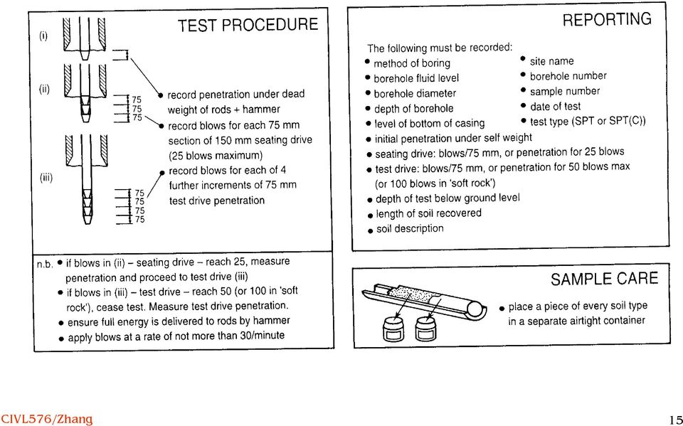
9 Test methods and standards UK & Hong Kong practice BS 1377:1990 Part 9, Section 3.3 (Determination of the penetration resistance using the split-barrel sampler (the Standard Penetration Test, SPT) a requirement to drill for at least 1 m before carrying out an SPT a return to a 63.5-kg (140 lb) drive weight the specification of an anvil mass between 15 kg and 20 kg a specified maximum overall weight for the drive assembly (or trip hammer) of 115 kg the introduction of a maximum rod weight of 10 kg/m the specification of a maximum permitted curvature for bent rods, in the form of a relative deflection of 1/1000 maximum blow counts for the seating drive and test drive: In seating drive In test drive Soil Soft rock In HK (GEO 1995), a SPT test should be terminated when any increment of 75 mm penetration cannot be achieved after 100 blows or where the total number of blows, excluding the seating drive, reaches 200. where the penetration under the dead weight of the rods and hammer exceeds 450 mm, the N value is recorded as zero. CIVL576/Zhang 9

10 1995 GEO Term Contract Specification for SPT CIVL576/Zhang 10

11 BS 1377 split-barrel samplers (a) BS 1377: 1975, (b) BS 1377: 1990 CIVL576/Zhang 11

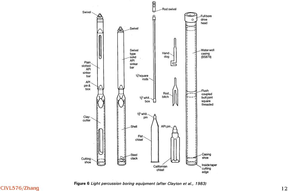
12 CIVL576/Zhang 12
13 The tool consists of three components: An inner stem connected at its base to an anvil ('drive-head' or 'striker plate') which screws directly to the drill rods. Current British anvils are large, weighing up to 20 kg. A 140-lb cylindrical weight which has a small central hole allowing it to slide freely over the inner stem. An outer tube assembly with pawls at its base. These pawls pick up the 140-lb weight and release it when the weight has been lifted 30-in above the upper surface of the striker plate. CIVL576/Zhang 13

14 British standard requirements for the SPT CIVL576/Zhang 14

15 CIVL576/Zhang 15
16 Test procedures in BS 1377: 1990 BS 1377: 1990 requires that the borehole shall be cleaned using equipment which ensures that the material in the test section is 'relatively undisturbed'. Common practice in granular soils is to use a full-diameter shell or bailer. The maximum depth of the shell is rarely checked, but it is common for the driller to lower a weighted tape to check the level of the bottom of the hole. The depth of the bottom of the casing is normally estimated from the number of casing lengths in use and the stickup at ground level. While the level of the bottom of the hole can be calculated, the thickness of disturbed soil or material fallen from the sides of the hole will not be known. The split-barrel sampler is then lowered on rods to the bottom of the hole and the trip hammer assembly connected. The SPT tool penetrates under the dead-weight of the rods and trip hammer, before being driven the 150 mm of the seating drive. The blows for the seating drive are recorded for two 75 mm increments of penetration, although this is optional in the current British Standard. It is commonly assumed that the 150 mm seating drive penetrates completely the zone of soil disturbed by the action of boring, but in some cases (for example, in granular soil) this may not be so. The sampler is then driven a further 300 mm, sometimes recording the blows for each of four 75 mm increments of penetration, sometimes for two 150 mm increments, and occasionally even for a single 300 mm drive. The rate of application of blows is not standardised, but may typically be about blows per minute. The total blows for the last 300 mm of penetration is the penetration resistance, N. When values are obtained using the standard cutting shoe, the result is recorded either as SPT or as SPT (S) on the driller's daily report. When the solid 60 cone is in use, the test is recorded as SPT (cone) or SPT(C). CIVL576/Zhang 16

17 Test procedures in BS 1377:1990 (Cont.) Test procedures are varied for very hard soils, and sometimes for very soft or loose soils. In the case of hard soils, BS 1377 recommends a maximum of 25 blows for the seating drive, and 50 blows for the test drive in soils, or 100 blows for a test drive in 'soft rock', but no further detail is required other than the total penetration for these blow counts. A good practice, used by some contractors, is to record the penetration for increments of 20 blows. The previous British Standard did not give guidance on what should be done if more than 50 blows were used during the seating drive, and as a result many different procedures are adopted. The maximum number of blows to be given in an entire test (i.e. including the seating drive) varies from one investigation to another. Some drillers use a maximum of 50 blows, while other use 80 or even 100 blows, and there are often inconsistencies between drillers working for the same company, or between different sites investigated by the same specialist contractor. In very loose or soft soils the weight of the rods plus the trip hammer alone may cause the SPT tool to drop through part or all of the test section. Some operators record this as a zero penetration resistance. In other cases the tool is allowed to stabilise under its self weight before the seating drive (and therefore the blow count) is started. In very loose soils, where 15 blows or less achieve the total penetration of 450 mm, some engineers require that further penetration should be made until either the total blowcount exceeds 80 at the end of a penetration increment, or the total penetration exceeds 750 mm. This procedure may be helpful in demonstrating that boring disturbance has occurred, but its results should be clearly marked to distinguish it from the standard procedure. CIVL576/Zhang 17

18 The US practice ASTM split-barrel sampler (ASTM D , re-approved 1992) Similar to BS1377 except: Rods 41.2 mm OD and 28.5 mm ID are slightly lighter than AW rods. The borehole diameter must be between 57.2 and 162 mm. The use of a cathead to pull a rope attached to the hammer Core catchers may be fitted in the driving shoe to prevent sample loss. CIVL576/Zhang 18

19 ASTM D1586 test procedures Rest the split spoon on the bottom of the borehole. Drive the split spoon with the 140-lb. hammer falling 30 in and count the number of blows applied in each increment until either a total of 50 blows in any one increment, or a total of 100 blows is reached, or there is no observable penetration, or the full penetration of 18 in (450 mm) is achieved. Repeat the procedure every 5 ft (1.5 m) or closer in homogeneous strata, and at every stratum change. Record the number of blows for each 6 in (150 mm) penetration. If a full drive is achieved, add the blows for the last 300 mm of penetration, to give the penetration resistance N. If not, the number of blows for each complete or part increment shall be recorded on the boring log. Part increments of penetration shall be reported to the nearest 1 in. CIVL576/Zhang 19
 penetration. If a full drive is achieved, add the blows for the last 300 mm of penetration, to give the penetration resistance N.")
20 Worldwide practice summary CIVL576/Zhang 20

21 World-wide practice summary The ASTM standard for the SPT is widely used. An International Reference Test Procedure (IRTP) has been approved by the ISSMFE (see Appendix). All SPT tests should, ideally, conform to the essential elements of the IRTP, and these aspects of the SPT should be reported whenever SPT results are published. There are many variations in international SPT practice, which lead to differences in the penetration resistances determined in similar soil types. The main variations lie in The methods of drilling and supporting the hole The hammer mechanisms and rod sizes used There are also minor variations in the split-spoon geometry and the method of testing. CIVL576/Zhang 21
22 Standard penetration test (SPT) Evolution of SPT Test methods and standards Influence of ground conditions on penetration resistance SPT energy measurement and corrections for SPT Use of SPT results Profiling Soil classification Determination of geotechnical parameters Direct design uses Appendix: International reference test procedure IRTP CIVL576/Zhang 22
23 The influence of different practices and equipment on penetration resistance The result of a Standard Penetration Test is influenced by three main groups of factors, associated with: Drilling or boring technique Method of hole support Method of advancing the hole Size of hole SPT test equipment Hammer design Rod size Split-spoon design Test procedure Seating drive Rate of application of blows. Differences in drilling technique produce the largest differences in penetration resistance in granular soils. In this respect the driller plays the most important role; the manual dexterity and care which he uses while boring or raising and lowering tools in the hole may have as great an influence on penetration resistance as the soil itself. CIVL576/Zhang 23
24 Effect of practices on SPT values Fig. 14 CIVL576/Zhang 24
25 Summary Figure 14 summarises the effects of drilling, test equipment and test procedure on penetration resistance. The major factors are: in granular soils, and chalk, the disturbance caused by drilling in sands, the use of a solid cone in place of the spoon the omission of liners in the spoon the efficiency of the hammer. Of these the disturbance caused by drilling has the greatest effect. Drilling disturbance may be particularly large in uncemented granular deposits, and in chalk. Most, but not all, factors are likely to lead to blow counts which are too low. Exceptions can occur when rod energy is low or the bottom of the casing is below the test section. The use of the SPT cone should be discouraged, except where essential, such as in coarse granular soils. When the intention is to measure N values, standard 35 mm i.d. split spoons should be used, i.e. without liners. Hammer efficiency may be checked using energy measurement techniques. In the UK it is thought that the SPT is well standardised, giving about 70-75% of the free-fall hammer energy. SPT equipment used abroad should be carefully evaluated, because the energy delivered by the hammer may be quite variable and, on average, different to that given by UK automatic trip hammers. Other influences, such as rod bending, are thought to be of generally minor importance. But such factors cannot always be ignored, and may be considered important under particular circumstances. In clays, drilling disturbance is generally small, and the results of the SPT are therefore relatively reliable. SPT results are used in empirical calculations, and the test is therefore the basis upon which experience is transferred from site to site, and from engineer to engineer. This Section has shown that, under certain circumstances, the test may be greatly affected by factors other than the ground. CIVL576/Zhang 25
26 Influence of ground conditions on penetration resistance The SPT spoon, 50 mm in diameter, is forced into the ground by short pulses of hammer energy passing down the rods. Ground resistance is provided by friction on the outside and inside of the spoon, and by end-bearing. Thus the N value results from a test on a relatively small volume of ground, that is performed dynamically and intermittently, to failure, and beyond, in conditions which may be either undrained or partially drained. CIVL576/Zhang 26
27 The SPT in granular soil influence factors CIVL576/Zhang 27
28 Effect of σ v and Dr (Skempton 1986) N = D a + b, σ v r C oc a= 17-46, a material dependent parameter b= 17-28, a material dependent parameter C OC, a correction factor for over-consolidation The effect of σ v can be removed for NC soils by normalizing the penetration resistance to its equivalent value at σ v = 100 kpa using a depth correction factor: C N = N N 1 σ v = D 2 r ( a + b) ( a / b + 1) 2 Dr, σ v a + b 100 = (, a / b + σ /100) v K 0 /K 0NC CIVL576/Zhang 28
29 Influence of density Clayton et al. (1983) ( N ) 1 60 N = 60 ( in the range 2 D r 33 ~ 84) where (N 1 ) 60 is the blow count normalised to an effective overburden pressure of 100 kpa and corrected to 60% of free fall energy. Skempton (1986) CIVL576/Zhang 29
30 The SPT in cohesive soil The relationship between undrained shear strength of cohesive soil and SPT N is controlled by a number of factors: Plasticity Sensitivity Fissuring CIVL576/Zhang 30
31 Weak and weathered rocks The SPT provides one of the very few techniques by which information can be obtained on the mass properties of weak and weathered rocks. Some influence factors are: strength of the intact rock porosity of the intact rock spacing of joints aperture and tightness of joints the presence of hard inclusions (such as flint or core stone). When joints are widely spaced and tight, such as in less-weathered weak rocks, the resistance of the rock mass to penetration is a function of porosity and intact strength. A high porosity allows the fractured rock to be pushed aside; a low strength makes it easier for the split spoon to fracture the rock (Meigh, 1980; Leach and Thompson, 1979). A slight change in water content can greatly change the SPT N value in intact chalk (Clayton 1970) CIVL576/Zhang 31
32 Lack of strong correlation between SPT N value and weathering grade CIVL576/Zhang 32
33 Summary The SPT is a small diameter, dynamic test to failure. The N value will reflect these factors. In granular soil, a great many factors inter-react to produce the measured penetration resistance. Simple correlations, which do not consider more than one factor, are likely to be unreliable. The major factors controlling dynamic penetration resistance in granular soils are: Cementing and ageing Mean effective stress level Overconsolidation Relative density and particle size. There is a clear need for explicit standardisation of density descriptors used on the basis of SPT N value as part of sample description. The system recommended here uses N values corrected for both energy and overburden pressure. Whatever system is adopted, its basis must be clearly stated. In cohesive soils, undrained shear strength is the main factor controlling penetration resistance. The measured value of undrained shear strength obtained from other in-situ or laboratory tests depends upon test size and method, thus affecting correlations with the SPT. Correlations between undrained shear strength and SPT N will depend upon: The method of measuring C u The sensitivity of the soil Fissuring. Available evidence suggests that the SPT provides a cheap reliable method of determining the undrained shear strength of firm to hard clays. The factors controlling dynamic penetration resistance in weak and weathered rock are: The strength of the intact rock The porosity of the intact rock The spacing, aperture and tightness of joints The presence of hard inclusions, such as flint or chert. The SPT cannot be used to provide reliable estimates of the visual weathering grade of chalk. Although the SPT cannot be expected to provide precise estimates of weak rock parameters, it is one of very few methods available. Therefore, in order to enhance its reliability, site specific correlation with directly determined parameters should be carried out whenever possible. CIVL576/Zhang 33
34 Standard penetration test (SPT) Evolution of SPT Test methods and standards Influence of ground conditions on penetration resistance SPT energy measurement and corrections for SPT Use of SPT results Profiling Soil classification Determination of geotechnical parameters Direct design uses Appendix: International reference test procedure IRTP CIVL576/Zhang 34
35 SPT energy measurement and corrections for SPT Skempton (1986) stated that the energy transmitted by a particular hammer and rod system would significantly affect the penetration resistance. Energy measurements can be made with the use of a pile driving analyzer (PDA) following ASTM D SPT values should be corrected to a common reference energy rating. Skempton (1986) proposed the use of 60% of the free fall energy as the reference energy rating. CIVL576/Zhang 35
36 PDA test CIVL576/Zhang 36
37 PDA force F(t) and velocity v(t) records Force (kip) Z Velocity Force Time (ms) CIVL576/Zhang 37
38 SPT energy rating The energy transferred to the SPT rods E r from beginning to t 2 is E r = 2 0 F( t) v( t) dt Free fall energy t E* = m g h = 63.5 x g x 0.76 = 483 J Rod energy ratio E R r (or hammer energy transfer efficiency E m ) is a measure of the energy efficiency of a hammer system: ER r = 100 E r / E* CIVL576/Zhang 38
39 (GEO 1997 TN2/97) CIVL576/Zhang 39
40 SPT N correction for test procedure The variations in testing procedure may be at least partially compensated by converting thee measured N to N 60 as follows (Skempton 1986): N 60 = E m CBCSC 0.60 R N N 60 = SPT N value corrected for field procedure E m = hammer energy transfer efficiency C B = borehole diameter correction C S = sampler correction C R = rod length correction N = measured SPT N value CIVL576/Zhang 40
41 SPT N correction for overburden stress The SPT data also should be adjusted using an overburden correction that compensate for the effective stress. The overburden correction adjusts the measured N values to what they would have been if the vertical effective stress σ z was 100 kpa. Liao and Whitman (1985) proposed: ( N 1 ) 60 = N kpa σ, z (N 1 ) 60 SPT N value corrected for field procedure and overburden stress σ v = vertical effective stress at the test location N 60 = SPT N value corrected for field procedure CIVL576/Zhang 41
42 Standard penetration test (SPT) Evolution of SPT Test methods and standards SPT energy measurement and corrections for SPT Influence of ground conditions on penetration resistance Use of SPT results Profiling Soil classification Determination of geotechnical parameters Direct design uses Appendix: International reference test procedure IRTP CIVL576/Zhang 42
43 Use of SPT results The SPT has been used for many purposes. At its simplest, it is a lowquality sampler. At its most useful it is a rapid, inexpensive, qualitative test which can provide data even when other techniques of sampling or testing are not viable or cannot be justified financially. The earliest application, the prediction of the allowable pressure of shallow foundations on sand, fulfilled a major need. Increasing use of the test then led to attempts to correlate its results with other geotechnical characteristics. Starting from site-specific correlations, more general ones have been proposed. But all too often specific correlations have been applied to inappropriate circumstances - in spite of the warnings of the original authors that such correlations were of limited validity. From the previous sections it can be seen that the SPT will often yield data which are, to some extent, affected by factors other than soil conditions. It is not, then, a test which yields data of great subtlety and precision. But this is not to deny its usefulness, given reasonable care in the pre-test work and testing according to sound established principles. CIVL576/Zhang 43
44 Applications of SPT Other applications: Profiling Soil classification CIVL576/Zhang 44
45 Profiling Profiling is carried out during ground investigation in order to establish boundaries between different soil or rock types. Dynamic penetrometers of different sizes are used to make crude estimates of penetration resistance at different depths and locations across a site. When used as a dynamic penetrometer, the SPT will need to be carried out frequently, say at 1 m centres in each borehole. CIVL576/Zhang 45
46 Soil classification Classification is the process used during ground investigation to divide soil and rock into a limited number of groups, each of which contains materials expected to have broadly similar engineering behaviour. The engineering parameters which are of most importance in estimating behaviour are strength, compressibility and permeability and rate of consolidation. The methods most commonly used for classification are sample description, moisture content and plasticity testing (for cohesive soils) and particle size distribution (for granular soils). Classification with the SPT is made possible because the test combines both a sampler (albeit of very poor quality and unable to sample coarse granular soils) and a penetrometer. CIVL576/Zhang 46
47 Determination of geotechnical parameters CIVL576/Zhang 47
48 Estimation of parameters in granular soils-effective angle of friction φ Use of Peck, Hansen and Thornburn s chart Mitchell et al (1978) chart: recognises the influence of vertical effective stress. CIVL576/Zhang 48
49 Discussion on φ φ is a function of State (density and stress) Grain characteristics Stress path The strength of soil may be derived from The critical state angle of friction φ cv A dilatancy component, φ -φ cv Effective stress Cementing φ cv = 33 for quartz sands, 37 for feldspathic sands (Bolton 1986) φ cv = for uniformly graded quartz sands, for sand containing feldspar, for well graded sands (Youd 1973) Peak friction angle from direct shear at plane strain condition CIVL576/Zhang 49
50 Estimation of parameters in granular soils - Stiffness Stiffness is a function of strain level, stress path, stress history etc. K' = vp' λ f or virgi nl oadi ng; vp' κ f or unl oadi ng Stroud (1989) E /N 60 = 1.0 (MPa) at a factor of safety of 3.0 Many foundations have FS values > 3.0 so E /N 60 may rise to about 2 MPa for NC sands, and to 16 for OC sands and gravels. CIVL576/Zhang 50
51 Correlations for HK soils (GEO 1997 TN2/97) CIVL576/Zhang 51
52 Other correlations CIVL576/Zhang 52
53 Estimation of parameters in fine-grained soils - Undrained shear strength C u = f 1 N 60 f 1 depends slightly on the plasticity of the clay. CIVL576/Zhang 53
54 Estimation of parameters in fine-grained soils - Compressibility Undrained Young s modulus E u E u /N = (MPa), likely to be reasonable for design for a wide range of degree of loading (q/q ult ) down to about 0.1 (Butler 1975) At smaller strains, E u /N = (MPa) Drained Young s modulus E E /N = (MPa) (Butler 1975) for London clay E /N = 0.9 (MPa) for a range of clays at q/q ult = Both E u and E are a function of strain level. CIVL576/Zhang 54
55 Direct design uses Design can proceed directly from the SPT N value as an input parameter to the value to be calculated (e.g., pile capacity) without providing any estimates of soil parameters. Examples to be illustrated Design of piles Liquefaction potential in granular soils CIVL576/Zhang 55
56 Design of piles shaft resistance f s = α + β N (Poulos 1989) f s is in kpa α and β are constants depending upon Soil and pile type Construction method (e.g., for driven piles, shaft resistance will depend upon the extend to which the pile displaces the soil, upon the rate at which excess pore water pressures can dissipate during and after driving and upon the amount of lateral movement allowed during driving.) CIVL576/Zhang 56
57 Design of piles toe resistance q b = K N (kpa) (Poulos 1989) The behaviour of piles in endbearing is barely observed, since shaft resistance must be substantially mobilized before end bearing is brought into play. Estimates of end-bearing in the literature are probably not of great accuracy. Correlations can only be used in the region where data were extracted. CIVL576/Zhang 57
58 Liquefaction potential in granular soils (Seed et al. 1983, 1985) During an earthquake, the average cyclic stress ratio in soil is, τ σ av, 0 a = 0.65 g max σ σ 0, 0 where τ av = average applied shear stress σ o '= effective overburden stress at the depth under consideration σ o = total overburden stress at the depth under consideration a max = maximum acceleration at ground surface r d = a stress reduction factor, which decreases from 1 at the ground surface to about 0.9 at a depth of 10 m. The limiting cyclic stress ratio above which liquefaction may be expected to occur is a function of Corrected SPT-N ((N 1 ) 60 corrected to 60% energy ratio and to an overburden pressure of 100 kpa) The fines content The magnitude of the earthquake CIVL576/Zhang 58 r d
59 The SPT procedure to be adopted when using these figures is (Seed et al. 1985): mm dia. rotary borehole with bentonite drilling mud. Upward deflected drilling mud at bit (tricone or baffled drag bit). Standard split spoon (34.5 mm internal diameter, 50.8 mm outside diameter - i.d. to be constant along length of barrel). A or AW drill rods to 15 m, N or NW rods at greater depth. 60% free-fall energy blows per minute. Penetration resistance measured over penetration range mm. CIVL576/Zhang 59
Geotechnical Measurements and Explorations Prof. Nihar Ranjan Patra Department of Civil Engineering Indian Institute of Technology, Kanpur
 Geotechnical Measurements and Explorations Prof. Nihar Ranjan Patra Department of Civil Engineering Indian Institute of Technology, Kanpur Lecture No. # 13 (Refer Slide Time: 00:18) So last class, it was
INDIRECT METHODS SOUNDING OR PENETRATION TESTS. Dr. K. M. Kouzer, Associate Professor in Civil Engineering, GEC Kozhikode
 INDIRECT METHODS SOUNDING OR PENETRATION TESTS STANDARD PENETRATION TEST (SPT) Reference can be made to IS 2131 1981 for details on SPT. It is a field edtest to estimate e the penetration e resistance
Site Investigation. Some unsung heroes of Civil Engineering. buried right under your feet. 4. Need good knowledge of the soil conditions
 This is an attempt to create a stand alone self learning module on site investigation. Fasten your seat belts. Sit back, relax and enjoy. 1 2 Site Investigation Some unsung heroes of Civil Engineering
Module 1 : Site Exploration and Geotechnical Investigation. Lecture 4 : In-situ tests [ Section 4.1: Penetrometer Tests ] Objectives
![Module 1 : Site Exploration and Geotechnical Investigation. Lecture 4 : In-situ tests [ Section 4.1: Penetrometer Tests ] Objectives](/thumbs/26/8734290.jpg "Module 1 : Site Exploration and Geotechnical Investigation. Lecture 4 : In-situ tests [ Section 4.1: Penetrometer Tests ] Objectives") Lecture 4 : In-situ tests [ Section 4.1: Penetrometer Tests ] Objectives In this section you will learn the following Penetrometer Tests Standard penetration test Static cone penetration test Dynamic cone
Lecture 4 : In-situ tests [ Section 4.1: Penetrometer Tests ] Objectives In this section you will learn the following Penetrometer Tests Standard penetration test Static cone penetration test Dynamic cone
INSITU TESTS! Shear Vanes! Shear Vanes! Shear Vane Test! Sensitive Soils! Insitu testing is used for two reasons:!
 In-situ Testing! Insitu Testing! Insitu testing is used for two reasons:! To allow the determination of shear strength or penetration resistance or permeability of soils that would be difficult or impossible
c. Borehole Shear Test (BST): BST is performed according to the instructions published by Handy Geotechnical Instruments, Inc.
: BST is performed according to the instructions published by Handy Geotechnical Instruments, Inc.") Design Manual Chapter 6 - Geotechnical 6B - Subsurface Exploration Program 6B-2 Testing A. General Information Several testing methods can be used to measure soil engineering properties. The advantages,
Design Manual Chapter 6 - Geotechnical 6B - Subsurface Exploration Program 6B-2 Testing A. General Information Several testing methods can be used to measure soil engineering properties. The advantages,
INTERNATIONAL JOURNAL OF CIVIL AND STRUCTURAL ENGINEERING Volume 3, No 3, 2013
 INTERNATIONAL JOURNAL OF CIVIL AND STRUCTURAL ENGINEERING Volume 3, No 3, 2013 Copyright by the authors - Licensee IPA- Under Creative Commons license 3.0 Research article ISSN 0976 4399 Reliability of
How To Design A Foundation
 The Islamic university - Gaza Faculty of Engineering Civil Engineering Department CHAPTER (2) SITE INVESTIGATION Instructor : Dr. Jehad Hamad Definition The process of determining the layers of natural
CIVL451. Soil Exploration and Characterization
 CIVL451 Soil Exploration and Characterization 1 Definition The process of determining the layers of natural soil deposits that will underlie a proposed structure and their physical properties is generally
The physical survey is that part of site investigation which aims to determine the physical properties of the ground. These are required:
 Chapter 9 In situ testing INTRODUCTION The physical survey is that part of site investigation which aims to determine the physical properties of the ground. These are required: 1. to classify the soil
product manual HS-4210 HS-4210_MAN_09.08 Digital Static Cone Penetrometer
 HS-4210_MAN_09.08 product manual HS-4210 Digital Static Cone Penetrometer Introduction This Manual covers the measurement of bearing capacity using the Humboldt Digital Static Cone Penetrometer (DSCP).
Standard Test Procedures Manual
 STP 240-6 Standard Test Procedures Manual Section: PENETRATION TEST & SPLIT- BARREL SAMPLING 1. SCOPE 1.1. Description of Test This method describes the standard penetration test using the split-barrel
NEW DEVELOPMENTS AND IMPORTANT CONSIDERATIONS FOR STANDARD PENETRATION TESTING FOR LIQUEFACTION EVALUATIONS. Jeffrey A Farrar M.S.
 NEW DEVELOPMENTS AND IMPORTANT CONSIDERATIONS FOR STANDARD PENETRATION TESTING FOR LIQUEFACTION EVALUATIONS Jeffrey A Farrar M.S., P E 1 ABSTRACT Standard Penetration Tests (SPT) are often used for evaluating
A study on the Effect of Distorted Sampler Shoe on Standard Penetration Test Result in Cohesionless soil
 ISSN: 319-53 (An ISO 39: 00 Certified Organization) A study on the Effect of Distorted Sampler Shoe on Standard Penetration Test Result in Cohesionless soil Utpal Kumar Das Associate Professor, Department
KWANG SING ENGINEERING PTE LTD
 KWANG SING ENGINEERING PTE LTD 1. INTRODUCTION This report represents the soil investigation works at Aljunied Road / Geylang East Central. The objective of the soil investigation is to obtain soil parameters
Geotechnical Investigation using Standard Penetration Test (SPT) in Rangamati, Bandarban and Khagrachari Towns
 in Rangamati, Bandarban and Khagrachari Towns") 1. Introduction 1.1 Scope of Work The Asian Disaster Preparedness Centre (ADPC) is implementing the project Seismic Hazard and Vulnerability Mapping for Rangamati, Bandarban and Khagrachari Municipality.
1. Introduction 1.1 Scope of Work The Asian Disaster Preparedness Centre (ADPC) is implementing the project Seismic Hazard and Vulnerability Mapping for Rangamati, Bandarban and Khagrachari Municipality.
Pavements should be well drained both during and upon completion of construction. Water should not be allowed to pond on or near pavement surfaces.
 Project No. 208-8719 January, 2009 Ref: 2-8719BR Anthony Hudson - Broadscale Geotechnical Investigation - Proposed Commercial Development - 52 Old Pacific Highway, Pimpama Page 32 iii) Pavements should
GUIDELINE FOR HAND HELD SHEAR VANE TEST
 GUIDELINE FOR HAND HELD SHEAR VANE TEST NZ GEOTECHNICAL SOCIETY INC August 2001 CONTENTS Page 1.0 Introduction 2 2.0 Background 2 3.0 Recommended Practice 3 4.0 Undrained Shear Strength 3 5.0 Particular
Geotechnical Testing Methods II
 Geotechnical Testing Methods II Ajanta Sachan Assistant Professor Civil Engineering IIT Gandhinagar FIELD TESTING 2 1 Field Test (In-situ Test) When it is difficult to obtain undisturbed samples. In case
Figure 2.31. CPT Equipment
 Soil tests (1) In-situ test In order to sound the strength of the soils in Las Colinas Mountain, portable cone penetration tests (Japan Geotechnical Society, 1995) were performed at three points C1-C3
Anirudhan I.V. Geotechnical Solutions, Chennai
 Anirudhan I.V. Geotechnical Solutions, Chennai Often inadequate In some cases, excess In some cases, disoriented Bad investigation Once in a while good ones Depends on one type of investigation, often
Soil behaviour type from the CPT: an update
 Soil behaviour type from the CPT: an update P.K. Robertson Gregg Drilling & Testing Inc., Signal Hill, California, USA ABSTRACT: An initial application of CPT results is to evaluate soil type and soil
Table of Contents 10.1 GENERAL... 10.1-1
 Table of Contents Section Page 10.1 GENERAL... 10.1-1 10.1.1 Overview... 10.1-1 10.1.2 Role of Uncertainty in Property Interpretation... 10.1-1 10.1.3 Role of Drainage in Property Interpretation... 10.1-2
GEOTECHNICAL ENGINEERING II. Subject Code : 06CV64 Internal Assessment Marks : 25 PART A UNIT 1
 GEOTECHNICAL ENGINEERING II Subject Code : 06CV64 Internal Assessment Marks : 25 PART A UNIT 1 1. SUBSURFACE EXPLORATION 1.1 Importance, Exploration Program 1.2 Methods of exploration, Boring, Sounding
SPECIFICATION FOR DYNAMIC CONSOLIDATION / DYNAMIC REPLACEMENT
 SPECIFICATION FOR DYNAMIC CONSOLIDATION / DYNAMIC REPLACEMENT 1.0 SOIL IMPROVEMENT 1.1 General Soil Investigation Information are provided in Part B1 annex as a guide to the Contractor for his consideration
T2: Reduce overall transport cost by cost effective road rehabilitation and maintenance
 PROJECT REPORT PR/INT/277/04 Dynamic Cone Penetrometer tests and analysis Technical Information Note By Colin Jones Sector: Theme: Project Title: Project Reference: Transport T2: Reduce overall transport
DYNAMIC CONE PENETRATION TEST INSTRUCTIONAL MANUAL GEOTECHANICAL
 DYNAMIC CONE PENETRATION TEST INSTRUCTIONAL MANUAL GEOTECHANICAL J. P. Scientific Instruments 7, Civil Lines, Roorkee-247667 DYNAMIC CONE PENETRATION TEST CONTENTS: PAGE NO. 1.0 INTRODUCTION 03 2.0 PROBLEM
System. Stability. Security. Integrity. 150 Helical Anchor
 Model 150 HELICAL ANCHOR System PN #MBHAT Stability. Security. Integrity. 150 Helical Anchor System About Foundation Supportworks is a network of the most experienced and knowledgeable foundation repair
Numerical Analysis of Texas Cone Penetration Test
 International Journal of Applied Science and Technology Vol. 2 No. 3; March 2012 Numerical Analysis of Texas Cone Penetration Test Nutan Palla Project Engineer, Tolunay-Wong Engineers, Inc. 10710 S Sam
Geotechnical Investigation Test Report
 Geotechnical Investigation Test Report Report No. htsc/rcd/ 3457 Dated: - 20/03/2010 Asphalt Standard Penetration Test as per IS 2131 ------------- IS 6403 Soil Job Card No - 1649 Cement Client/Department
CHAPTER 1 INTRODUCTION
 CHAPTER 1 INTRODUCTION 1.1 Introduction The design and construction of foundations require a good knowledge of the mechanical behaviour of soils and of their spatial variability. Such information can be
NOTES on the STANDARD PENETRATION TEST
 GE 441 Advanced Engineering Geology & Geotechnics Spring 2004 NOTES on the STANDARD PENETRATION TEST Origins of the Standard Penetration Test Around 1902 Colonel Charles R. Gow, owner of the Gow Construction
Cone Penetration Testing in Geotechnical Practice. Tom Lunne Peter K. Robertson John J.M. Powell
 Cone Penetration Testing in Geotechnical Practice Tom Lunne Peter K. Robertson John J.M. Powell BLACKIE ACADEMIC & PROFESSIONAL An Imprint of Chapman & Hall London Weinheim New York Tokyo Melbourne Madras
NOTES on the CONE PENETROMETER TEST
 GE 441 Advanced Engineering Geology & Geotechnics Spring 2004 Introduction NOTES on the CONE PENETROMETER TEST The standardized cone-penetrometer test (CPT) involves pushing a 1.41-inch diameter 55 o to
ASSESSMENT OF SHEAR WAVE VELOCITY FROM INDIRECT INSITU TESTS
 Proceedings of Indian Geotechnical Conference IGC-2014 December 18-20, 2014, Kakinada, India ASSESSMENT OF SHEAR WAVE VELOCITY FROM INDIRECT INSITU TESTS Kant, L., M. Tech Student, Department of Earthquake
COMPENDIUM OF INDIAN STANDARDS ON SOIL ENGINEERING PART 2
 (PREVIEW) SP 36 (Part 2) : 1988 COMPENDIUM OF INDIAN STANDARDS ON SOIL ENGINEERING PART 2 IS 1893 : 1979 (Reaffirmed 1987) CODE OF PRACTICE FOR SUBSURFACE INVESTIGATION FOR FOUNDATIONS 1.1 This code deals
Chittagong Hill Tract Development Facilities (CHTDF) United Nations Development Programme
 United Nations Development Programme") Chittagong Hill Tract Development Facilities (CHTDF) United Nations Development Programme Main Report Deliverable 02 Sub-Surface Properties of Soil Development in Rangamati, Bandarban and Khagrachari Municipality
Chittagong Hill Tract Development Facilities (CHTDF) United Nations Development Programme Main Report Deliverable 02 Sub-Surface Properties of Soil Development in Rangamati, Bandarban and Khagrachari Municipality
Chapter 7 Analysis of Soil Borings for Liquefaction Resistance
 Chapter 7 Analysis of Soil Borings for Liquefaction Resistance 7.1. Introduction. This chapter addresses the analysis of subsurface soil data to determine the factor of safety against liquefaction and
Using Combination of SPT, DMT and CPT to Estimate Geotechnical Model for a Special Project in Turkey
 Using Combination of SPT, DMT and CPT to Estimate Geotechnical Model for a Special Project in Turkey Figen Orhun Onal GE, M.Sc., Site Works Manager, Zemin Etud ve Tasarım A.Ş., Istanbul, [email protected]
CPTic_CSM8. A spreadsheet tool for identifying soil types and layering from CPTU data using the I c method. USER S MANUAL. J. A.
 CPTic_CSM8 A spreadsheet tool for identifying soil types and layering from CPTU data using the I c method. USER S MANUAL J. A. Knappett (2012) This user s manual and its associated spreadsheet ( CPTic_CSM8.xls
Soil Classification Through Penetration Tests
 Pak. J. Engg. & Appl. Sci. Vol. 9, Jul., 2011 (p. 76-86) Soil Classification Through Penetration Tests A. H. Khan, A. Akbar, K. Farooq, N. M. Khan, M. Aziz and H. Mujtaba Department of Civil Engineering,
Cone Penetration Testing (CPT) Michael Bailey, P.G. U.S. Army Corps of Engineers, Savannah District
 Michael Bailey, P.G. U.S. Army Corps of Engineers, Savannah District") Cone Penetration Testing (CPT) Michael Bailey, P.G. U.S. Army Corps of Engineers, Savannah District Recommended publications ASTM D 5778-07 Standard Test Method for Electronic Friction Cone and Piezocone
Cone Penetration Testing (CPT) Michael Bailey, P.G. U.S. Army Corps of Engineers, Savannah District Recommended publications ASTM D 5778-07 Standard Test Method for Electronic Friction Cone and Piezocone
Method Statement FOR. Soil Investigation
 Method Statement FOR Soil Investigation PREPARED BY JUNE 2010 Infratech ASTM CO., LTD. TABLE OF CONTENTS Chapter Title Page Table of Contents..1 List of Appendix... 2 List of Table... 2 List of Figures...
1 Mobilisation and demobilisation 1 Deep boring sum 2 Cone penetration tests sum 3 Miscellenous tests sum
 Malaysian Civil Engineering Standard Method of Measurement (MyCESMM) CLASS D: SITE INVESTIGATION WORK Measurement covered under other classes: Excavation not carried out for the purpose of soil investigation
CHAPTER 9 SOIL EXPLORATION 9.1 INTRODUCTION
 CHAPTER 9 SOIL EXPLORATION 9.1 INTRODUCTION The stability of the foundation of a building, a bridge, an embankment or any other structure built on soil depends on the strength and compressibility characteristics
Dynamic Load Testing of Helical Piles
 Dynamic Load Testing of Helical Piles ANNUAL KANSAS CITY SPECIALTY SEMINAR 2014 JANUARY 10, 2014 Jorge Beim JWB Consulting LLC Pile Dynamics, Inc. Main Topics Brief description of the Dynamic Load Test
CONE PENETRATION TESTING AND SITE EXPLORATION IN EVALUATING THE LIQUEFACTION RESISTANCE OF SANDS AND SILTY SANDS ABSTRACT
 CONE PENETRATION TESTING AND SITE EXPLORATION IN EVALUATING THE LIQUEFACTION RESISTANCE OF SANDS AND SILTY SANDS E. J. Newman 1, T. D. Stark 2, and S. M. Olson 3 ABSTRACT Refined relationships between
Applicability of Standard Penetration Test in Bangladesh and Graphical Representation of SPT-N Value
 International Journal of Science and Engineering Investigations vol. 4, issue 41, June 2015 ISSN: 2251-8843 Applicability of Standard Penetration Test in Bangladesh and Graphical Representation of SPT-N
Standard Test Method for Mechanical Cone Penetration Tests of Soil 1
 Designation: D 3441 98 AMERICAN SOCIETY FOR TESTING AND MATERIALS 100 Barr Harbor Dr., West Conshohocken, PA 19428 Reprinted from the Annual Book of ASTM Standards. Copyright ASTM Standard Test Method
ENCE 4610 Foundation Analysis and Design
 This image cannot currently be displayed. ENCE 4610 Foundation Analysis and Design Shallow Foundations Total and Differential Settlement Schmertmann s Method This image cannot currently be displayed. Strength
TECHNICAL REPORT ON SCALA DYNAMIC CONE PENETROMETER IRREGULARITY
 TECHNICAL REPORT ON SCALA DYNAMIC CONE PENETROMETER IRREGULARITY CETANZ Technical Report TR 1 Author(s) SJ Anderson, Geotechnics Ltd Report Date First Issue May 2010 Report Revision Date September 2011
Comparison of Continuous Dynamic Probing with the Standard Penetration Test for Highly Weathered Limestone of Eastern Sudan
 Comparison of Continuous Dynamic Probing with the Standard Penetration Test for Highly Weathered Limestone of Eastern Sudan Prof. Dr. Khairul Anuar Kassim Deputy Dean, Research and Graduate Studies, Faculty
Eurocode 7 - Geotechnical design - Part 2 Ground investigation and testing
 Brussels, 18-20 February 2008 Dissemination of information workshop 1 Eurocode 7 - Geotechnical design - Part 2 Ground investigation and testing Dr.-Ing. Bernd Schuppener, Federal Waterways Engineering
FINAL REPORT ON SOIL INVESTIGATION
 FINAL REPORT ON SOIL INVESTIGATION FOR PROPOSED CONSTRUCTION AT SS-6B AREA AT HPCL VISAKH REFINERY VISAKHAPATNAM ANDHRA PRADESH J.J. ASSOCIATES(VISAKHAPATNAM) AETP(P) LIMITED #11-6-3, RockDale Layout,
INTRODUCTION TO SOIL MODULI. Jean-Louis BRIAUD 1
 INTRODUCTION TO SOIL MODULI By Jean-Louis BRIAUD 1 The modulus of a soil is one of the most difficult soil parameters to estimate because it depends on so many factors. Therefore when one says for example:
DIRECT PUSH DRILLING.
 DIRECT PUSH DRILLING. CONCEPT. Direct Push Drilling is a method of drilling and sampling where the tools are pushed or driven into the ground. No rotation is involved so all the samples are uncontaminated
TECHNICAL Summary. TRB Subject Code:62-7 Soil Foundation Subgrades February 2003 Publication No.: FHWA/IN/JTRP-2002/30, SPR-2362
 INDOT Research TECHNICAL Summary Technology Transfer and Project Implementation Information TRB Subject Code:62-7 Soil Foundation Subgrades February 3 Publication No.: FHWA/IN/JTRP-2/3, SPR-2362 Final
LABORATORY DETERMINATION OF CALIFORNIA BEARING RATIO
 LABORATORY DETERMINATION OF CALIFORNIA BEARING RATIO STANDARD IS: 2720 (Part 16) 1979. DEFINITION California bearing ratio is the ratio of force per unit area required to penetrate in to a soil mass with
Module5: Site investigation using in situ testing
 Module5: Site investigation using in situ testing Topics: Introduction Penetration testing 1. Standard penetration test 2. Cone penetration test Strength and compressibility testing 1. Field vane shear
Fundamentals of CONE PENETROMETER TEST (CPT) SOUNDINGS. J. David Rogers, Ph.D., P.E., R.G.
 SOUNDINGS. J. David Rogers, Ph.D., P.E., R.G.") Fundamentals of CONE PENETROMETER TEST (CPT) SOUNDINGS J. David Rogers, Ph.D., P.E., R.G. Cone Penetration Test CPT soundings can be very effective in site characterization, especially sites with discrete
Fundamentals of CONE PENETROMETER TEST (CPT) SOUNDINGS J. David Rogers, Ph.D., P.E., R.G. Cone Penetration Test CPT soundings can be very effective in site characterization, especially sites with discrete
PILE FOUNDATIONS FM 5-134
 C H A P T E R 6 PILE FOUNDATIONS Section I. GROUP BEHAVIOR 6-1. Group action. Piles are most effective when combined in groups or clusters. Combining piles in a group complicates analysis since the characteristics
USE OF CONE PENETRATION TEST IN PILE DESIGN
 PERIODICA POLYTECHNICA SER. CIV. ENG. VOL. 47, NO. 2, PP. 189 197 (23) USE OF CONE PENETRATION TEST IN PILE DESIGN András MAHLER Department of Geotechnics Budapest University of Technology and Economics
HAULBOWLINE, CORK STATIC CONE PENETRATION TESTS FACTUAL REPORT
 HAULBOWLINE, CORK STATIC CONE PENETRATION TESTS FACTUAL REPORT CONE PENETRATION TESTS Cone resistance Local friction Porewater pressure Dissipations REPORT NO: RRM CONTRACT NO: GLOVER SITE INVESTIGATIONS
By D. P. StewarP and M. F. Randolph z
 T-BAR PENETRATION TESTING IN SOFT CLAY By D. P. StewarP and M. F. Randolph z ABSTRACT: A t-bar penetration test for soft clay that can be performed with existing cone penetration test (CPT) equipment is
King Saud University College of Engineering Civil Engineering Department DEFORMATION OF PARTIALLY SATURATED SAND. Sultan Musaed Al-Ghamdi
 King Saud University College of Engineering Civil Engineering Department DEFORMATION OF PARTIALLY SATURATED SAND By Sultan Musaed Al-Ghamdi Submitted in Partial Fulfillment of The Required For the Degree
Improvement in physical properties for ground treated with rapid impact compaction
 International Journal of the Physical Sciences Vol. 6(22), pp. 5133-5140, 2 October 2011 Available online at http://www.academicjournals.org/ijps ISSN 1992-1950 2011 Academic Journals Full Length Research
Effect of grain size, gradation and relative density on shear strength and dynamic cone penetration index of Mahi, Sabarmati and Vatrak Sand
 Discovery ANALYSIS The International Daily journal ISSN 2278 5469 EISSN 2278 5450 2015 Discovery Publication. All Rights Reserved Effect of grain size, gradation and relative density on shear strength
Numerical Simulation of CPT Tip Resistance in Layered Soil
 Numerical Simulation of CPT Tip Resistance in Layered Soil M.M. Ahmadi, Assistant Professor, [email protected] Dept. of Civil Engineering, Sharif University of Technology, Tehran, Iran Abstract The paper
Local Authority Building Control Technical Information Note 3 Driven and In-situ Piled Foundations
 Local Authority Building Control Technical Information Note 3 Driven and In-situ Piled Foundations Cambridge City Council - East Cambridgeshire District Council - Fenland District Council, Huntingdonshire
Caltrans Geotechnical Manual
 Cone Penetration Test The cone penetration test (CPT) is an in-situ sounding that pushes an electronic penetrometer into soil and records multiple measurements continuously with depth. Compared with rotary
QUESTION TO AUDIENCE
 Site investigation some aspects of EN1997 Part 2 David Norbury David Norbury Limited BGA Symposium Eurocode 7 Today and Tomorrow, Cambridge, England, March 2011 QUESTION TO AUDIENCE How many of you have
TECHNICAL NOTE: SI 01 SPECIFIC REQUIREMENTS FOR THE ACCREDITATION OF INSPECTION BODIES FOR SITE INVESTIGATION
 ACCREDITATION SCHEME FOR INSPECTION BODIES TECHNICAL NOTE: SI 01 SPECIFIC REQUIREMENTS FOR THE ACCREDITATION OF INSPECTION BODIES FOR SITE INVESTIGATION Technical Note SI 01: 3 February 2016 The SAC Accreditation
Dyanmic Cone. for Shallow
 Dyanmic Cone for Shallow George F. Sowers' and Charles S. Hedge* REFERENCE: George F. Sowers and Charles S. Hedges, "Dynamic Cone for Shallow In-Situ Penetration Testing," Vane Shear and Cone Penetration
1.0 INTRODUCTION 1 2.0 SCOPE OF WORK 2 3.0 EXECUTION OF FIELD WORK 2 4.0 LABORATORY TESTS 8 5.0 FINDINGS OF THE GEOTECHNICAL INVESTIGATION 9
 REPORT ON GEOTECHNICAL INVESTIGATION FOR LPG MOUNDED STORAGE AT VISAKHA REFINERY, MALKAPURAM, VISAKHAPATNAM (A.P) FOR HINDUSTAN PETROLEUM CORPORATION LIMITED CONTENTS SR.NO. DESCRIPTION PAGE NO. 1.0 INTRODUCTION
EVALUATION OF TEXAS CONE PENETROMETER TEST TO PREDICT UNDRAINED SHEAR STRENGTH OF CLAYS HARIHARAN VASUDEVAN
 EVALUATION OF TEXAS CONE PENETROMETER TEST TO PREDICT UNDRAINED SHEAR STRENGTH OF CLAYS by HARIHARAN VASUDEVAN Presented to the Faculty of the Graduate School of The University of Texas at Arlington in
A Ground Improvement Update from TerraSystems
 TERRANOTES A Ground Improvement Update from TerraSystems SOIL MODULUS AFTER GROUND IMPROVEMENT Evaluation of ground improvement is accomplished using a variety of methods, from simple elevation surveys
International Journal of Scientific & Engineering Research, Volume 4, Issue 9, September-2013 409 ISSN 2229-5518
 International Journal of Scientific & Engineering Research, Volume 4, Issue 9, September-2013 409 Estimation of Undrained Shear Strength of Soil using Cone Penetration Test By Nwobasi, Paul Awo Department
Use and Application of Piezocone Penetration Testing in Presumpscot Formation
 Use and Application of Piezocone Penetration Testing in Presumpscot Formation Craig W. Coolidge, P.E. Summit Geoengineering Services, Rockland, Maine ABSTRACT: This paper examines the advantages and limitations
HIGHWAYS DEPARTMENT GUIDANCE NOTES ON SOIL TEST FOR PAVEMENT DESIGN
 HIGHWAYS DEPARTMENT GUIDANCE NOTES ON SOIL TEST FOR PAVEMENT DESIGN Research & Development Division RD/GN/012 August 1990 HIGHWAYS DEPARTMENT GUIDANCE NOTES (RD/GN/012) SOIL TEST FOR PAVEMENT DESIGN Prepared
Ingeniería y Georiesgos Ingeniería Geotécnica Car 19 a Nº 84-14 of 204 ; TEL : 6916043 E-mail: [email protected]
 The plot below presents the cross correlation coeficient between the raw qc and fs values (as measured on the field). X axes presents the lag distance (one lag is the distance between two sucessive CPT
ANNEX D1 BASIC CONSIDERATIONS FOR REVIEWING STUDIES IN THE DETAILED RISK ASSESSMENT FOR SAFETY
 ANNEX D1 BASIC CONSIDERATIONS FOR REVIEWING STUDIES IN THE DETAILED RISK ASSESSMENT FOR SAFETY ANNEX D1: BASIC CONSIDERATIONS FOR REVIEWING STUDIES IN DRA FOR SAFETY D1-1 ANNEX D1 BASIC CONSIDERATIONS
BEARING CAPACITY AND SETTLEMENT RESPONSE OF RAFT FOUNDATION ON SAND USING STANDARD PENETRATION TEST METHOD
 SENRA Academic Publishers, British Columbia Vol., No. 1, pp. 27-2774, February 20 Online ISSN: 0-353; Print ISSN: 17-7 BEARING CAPACITY AND SETTLEMENT RESPONSE OF RAFT FOUNDATION ON SAND USING STANDARD
GUIDE TO CONE PENETRATION TESTING
 GUIDE TO CONE PENETRATION TESTING www.greggdrilling.com Engineering Units Multiples Micro (μ) = 10-6 Milli (m) = 10-3 Kilo (k) = 10 +3 Mega (M) = 10 +6 Imperial Units SI Units Length feet (ft) meter (m)
Penetrometer testing in residual soils from granitic rocks in the South of Portugal
 Penetrometer testing in residual soils from granitic rocks in the South of Portugal Isabel M. R. Duarte Department of Geosciences, University of Évora; Research Centre Industrial Minerals and Clays António
ESTIMATION OF UNDRAINED SETTLEMENT OF SHALLOW FOUNDATIONS ON LONDON CLAY
 International Conference on Structural and Foundation Failures August 2-4, 2004, Singapore ESTIMATION OF UNDRAINED SETTLEMENT OF SHALLOW FOUNDATIONS ON LONDON CLAY A. S. Osman, H.C. Yeow and M.D. Bolton
Work Type Definition and Submittal Requirements
 Work Type: Highway Materials Testing Geotechnical Laboratory Testing, Geotechnical Laboratory Testing, Standard Penetration (SPT) & Rock Coring, Cone Penetration Test, Solid Stem Auger Drilling, and Materials
Drained and Undrained Conditions. Undrained and Drained Shear Strength
 Drained and Undrained Conditions Undrained and Drained Shear Strength Lecture No. October, 00 Drained condition occurs when there is no change in pore water pressure due to external loading. In a drained
Micropiles Reduce Costs and Schedule for Merchant RR Bridge Rehabilitation
 Micropiles Reduce Costs and Schedule for Merchant RR Bridge Rehabilitation Jeff R. Hill, P.E. Hayward Baker Inc. 111 W. Port Plaza Drive Suite 600 St. Louis, MO 63146 314-542-3040 [email protected]
ALLOWABLE LOADS ON A SINGLE PILE
 C H A P T E R 5 ALLOWABLE LOADS ON A SINGLE PILE Section I. BASICS 5-1. Considerations. For safe, economical pile foundations in military construction, it is necessary to determine the allowable load capacity
CIV4249 1. SITE INVESTIGATION AND EXPLORATION TABLE OF CONTENTS
 Unit CIV4249: Foundation Engineering 1.1 CIV4249 1. SITE INVESTIGATION AND EXPLORATION TABLE OF CONTENTS 1. GENERAL... 2 1.1. Objectives... 2 1.2. Reasons for investigating Subsurface... 2 1.3. Sources
Penetration rate effects on cone resistance measured in a calibration chamber
 Penetration rate effects on cone resistance measured in a calibration chamber K. Kim Professional Service Industries, Inc, Houston, TX, USA M. Prezzi & R. Salgado Purdue University, West Lafayette, IN,
GUIDE TO CONE PENETRATION TESTING
 GUIDE TO CONE PENETRATION TESTING www.greggdrilling.com Engineering Units Multiples Micro (μ) = 10-6 Milli (m) = 10-3 Kilo (k) = 10 +3 Mega (M) = 10 +6 Imperial Units SI Units Length feet (ft) meter (m)
When to Use Immediate Settlement in Settle 3D
 When to Use Immediate Settlement in Settle 3D Most engineers agree that settlement is made up of three components: immediate, primary consolidation and secondary consolidation (or creep). Most engineers
Soil Mechanics. Outline. Shear Strength of Soils. Shear Failure Soil Strength. Laboratory Shear Strength Test. Stress Path Pore Pressure Parameters
 Soil Mechanics Shear Strength of Soils Chih-Ping Lin National Chiao Tung Univ. [email protected] 1 Outline Shear Failure Soil Strength Mohr-Coulomb Failure Criterion Laboratory Shear Strength Test
TITLE: DCP analysis and design of low volume roads by new TRL software UK DCP AUTHORS: Piouslin Samuel and Simon Done, TRL
 SEMINAR: SUSTAINABLE ACCESS AND LOCAL RESOURCE SOLUTIONS Date : 28 30 November 2005 TITLE: DCP analysis and design of low volume roads by new TRL software UK DCP AUTHORS: Piouslin Samuel and Simon Done,
Instrumented Becker Penetration Test for Liquefaction Assessment in Gravelly Soils
 Instrumented Becker Penetration Test for Liquefaction Assessment in Gravelly Soils Mason Ghafghazi 1, PhD, PEng. Jason DeJong 2, Professor Department of Civil and Environmental Engineering University of
High Strain Dynamic Load Testing of Drilled Shafts
 Supplemental Technical Specification for High Strain Dynamic Load Testing of Drilled Shafts SCDOT Designation: SC-M-712 (9/15) September 3, 2015 1.0 GENERAL This work shall consist of performing high-strain
FACTUAL GROUND INVESTIGATION
 FACTUAL GROUND INVESTIGATION REPORT COMMERCIAL/INDUSTRIAL REDEVELOPMENT OF LAND AT STEADMAN S WELTON CUMBRIA Web: www.geoenvironmentalengineering.com Telephone: 08456 768 895 Project Ref: 2013-657 Site
NUMERICAL MODELLING OF PIEZOCONE PENETRATION IN CLAY
 NUMERICAL MODELLING OF PIEZOCONE PENETRATION IN CLAY Ilaria Giusti University of Pisa [email protected] Andrew J. Whittle Massachusetts Institute of Technology [email protected] Abstract This paper
Testing Procedures. Note: Please refer to Table 2 for a list of completed borings.
 Testing Procedures Drilling and Sampling: Standard penetration tests (SPT) were conducted for every ten feet of boring advancement. SPT tests were conducted in accordance with ASTM D1586, using a 140 pound