SD95-16-G2. SD Department of Transportation Office of Research. Rural Road Design, Maintenance, and Rehabilitation Guide
|
|
|
- Eustace Gallagher
- 8 years ago
- Views:
Transcription
1 SD95-16-G2 SD Department of Transportation Office of Research Rural Road Design, Maintenance, and Rehabilitation Guide Prepared by ERES Consultants, Inc. 505 West University Champaign, IL September 1995

2 DISCLAIMER The contents of this report reflect the views of the authors who are responsible for the facts and accuracy of the data presented herein. The contents do not necessarily reflect the official views or policies of the South Dakota Department of Transportation, the State Transportation Commission, or the Federal Highway Administration. This report does not constitute a standard, specification, or regulation. ACKNOWLEDGMENTS This work was performed under the supervision of the SD95-16 Technical Panel: Ray Roggow... Gregory County Roger Muller... Turner County Hiene Junge... Codington County Ken Skorseth... South Dakota Technology Transfer Center Brett Hestdalen... Federal Highway Administration Toby Crow... Office of Planning and Programming Joe Feller... Office of Materials and Surfacing Terry Jorgensen... Office of Local Government Assistance David Huft... Office of Research Blair Lunde... Office of Research

3 TECHNICAL REPORT STANDARD TITLE PAGE 1. Report No. SD95-16-G2 2. Government Accession No. 3. Recipient's Catalog No. 4. Title and Subtitle Rural Road Design, Maintenance, and Rehabilitation Guide 5. Report Date September 22, Performing Organization Code 7. Author(s) Mr. Curt A. Beckemeyer and Mr. Trent J. McPeak 8. Performing Organization Report No. 9. Performing Organization Name and Address ERES Consultants, Inc. 505 West University Avenue Champaign, Illinois Sponsoring Agency Name and Address South Dakota Department of Transportation Office of Research 700 East Broadway Avenue Pierre, SD Work Unit No. 11. Contract or Grant No Type of Report and Period Covered Guideline 14. Sponsoring Agency Code 15. Supplementary Notes The Rural Road Design, Maintenance, and Rehabilitation Guide (SD95-16-G2) is part of a series of three guides. The other two guides are the Rural Road Condition Survey Guide (SD95-16-G1) and the Rural Road Management Guide (SD95-16-G3). 16. Abstract The Rural Road Design, Maintenance, and Rehabilitation Guide was developed to provide the counties of South Dakota with an established, uniform set of guidelines for the design, maintenance, and rehabilitation of rural roads. The guidelines address items such as roadway geometry (horizontal and vertical), typical roadway surface types, roadway surface design and repair, subgrade soils, and trench backfilling. The geometric-related guidelines are adapted from the SDDOT Secondary & Off-System Road Plan and the 1990 American Association of State Highway and Transportation Officials (AASHTO) manual, A Policy on Geometric Design of Highways and Streets. The geometry guidelines address design speed, roadway width, vertical grades, stopping sight distance, curvature, cross slope, superelevation, right-of-way (ROW) width, vertical clearance, and ditch slopes. The roadway surface-related guidelines pertain to the design, maintenance, and rehabilitation of the four types of roadway surfaces typically constructed on South Dakota s rural roads gravel, blotter, asphalt concrete, and portland cement concrete. The guidelines describe the primary design and performance characteristics of each surface type, provide design thicknesses, identify various repair techniques, and discuss the applicability of each technique. In addition, guidelines for the inspection and testing of materials and construction activities are discussed. 17. Keyword 18. Distribution Statement No restrictions. This document is available to the public from the sponsoring agency. 19. Security Classification (of this report) Unclassified Security Classification (of this page) 21. No. of Pages Price n/a Unclassified i

4 TABLE OF CONTENTS Page 1. INTRODUCTION GEOMETRIC DESIGN...3 Introduction...3 Geometric Requirements...3 Design Speed...7 Width of Roadway...7 Vertical Grades...7 Stopping Sight Distance...7 Minimum Curve Radius/Maximum Degree of Curvature...7 Pavement Surface Crown...8 Superelevation...8 Right-of-Way (ROW) Width...8 Vertical Clearance...8 Inslope TYPICAL ROADWAY SURFACE TYPES...11 Gravel-Surfaced Roads...11 Blotter (Chip Seal) Pavements...11 Asphalt Concrete Pavements...12 Portland Cement Concrete Pavements...14 PCC Pavement Types...14 Function of the Various Layers in a PCC Pavement GRAVEL ROAD DESIGN AND REPAIR...17 Gravel Road Repair Options...17 Typical Gravel Road Repair Techniques...19 Surface Blading...19 Regraveling...21 Dust Control...21 Cleaning Ditches...21 New or Reconstructed Gravel Roads...22 Typical Gravel Road Repair Frequency...22 iii

5 TABLE OF CONTENTS (continued) iv Page 5. FLEXIBLE PAVEMENT DESIGN AND REPAIR...25 Flexible Pavement Repair Options...25 Flexible Pavements in Excellent Condition (Rating Value of 86 to 100)...27 Flexible Pavements in Very Good Condition (Rating Value of 71 to 85)...27 Flexible Pavements in Good Condition (Rating Value of 56 to 70)...27 Flexible Pavements in Fair Condition (Rating Value of 41 to 55)...28 Flexible Pavements in Poor Condition (Rating Value of 26 to 40)...28 Flexible Pavements in Very Poor and Failed Condition (Rating Value of 0 to 25)...29 Flexible Pavement Repair Techniques...29 Crack Sealing...29 Pothole Patching...32 Patching of Alligator-Cracked Areas...32 Surface Treatments...33 AC Overlays...35 Partial-Depth Removal and Replacement of the AC Layer...38 New Construction or Reconstruction of Flexible Pavements RIGID PAVEMENT DESIGN AND REPAIR...43 Jointed Plain Concrete Pavement Repair Options...43 JPCP in Excellent Condition (Rating Value of 86 to 100)...43 JPCP in Very Good Condition (Rating Value of 71 to 85)...45 JPCP in Good Condition (Rating Value of 56 to 70)...45 JPCP in Fair Condition (Rating Value of 41 to 55)...45 JPCP in Poor Condition (Rating Value of 26 to 40)...46 JPCP in Very Poor and Failed Condition (Rating Value of 0 to 25)...46 Jointed Plain Concrete Pavement Repair Techniques...46 Joint and Crack Sealing...46 Partial-Depth Spall Repair...48 Full-Depth PCC Patches...49 Diamond Grinding...50 AC Overlays...50 Crack and Seat or Break and Seat Followed by an AC Overlay...50 New or Reconstructed JPCP...51 Jointed Plain Concrete Pavement Joints...53 Longitudinal Joint Spacing...53 Transverse Joint Spacing...53 Joint Design...54
...29 Flexible Pavement Repair Techniques...29 Crack Sealing...29 Pothole Patching.")
6 TABLE OF CONTENTS (continued) Page 7. SUBGRADE SOILS...55 Design Considerations...55 Construction Considerations...57 Drainage...60 Swelling Soils TRENCH BACKFILLING REFERENCES...63 APPENDIX A SDDOT JPCP JOINT DETAILS v

7 INTRODUCTION 1. INTRODUCTION This document is the second in a series of three manuals produced for the South Dakota Department of Transportation. It is intended for use by county superintendents and other county roadway agency personnel within the State of South Dakota for the efficient selection of maintenance, rehabilitation, and reconstruction alternatives for rural gravel, blotter, asphalt concrete (AC), and portland cement concrete (PCC) roads. The first manual, Rural Road Condition Survey Guide, provides a methodology for determining the condition of rural paved and gravel-surfaced roads. The third manual, Rural Road Management Guide, provides direction for establishing county-wide management systems for rural paved and gravel-surfaced roads. The Rural Road Design, Maintenance, and Rehabilitation Guide was developed to provide the counties of South Dakota with an established, uniform set of guidelines for the design, maintenance, and rehabilitation of rural roads. The guidelines address items such as roadway geometry (horizontal and vertical), typical roadway surface types, roadway surface design and repair, subgrade soils, and trench backfilling. The geometric-related guidelines are adapted from the SDDOT Secondary & Off- System Road Plan and the 1990 American Association of State Highway and Transportation Officials (AASHTO) manual, A Policy on Geometric Design of Highways and Streets. The geometry guidelines address design speed, roadway width, vertical grades, stopping sight distance, curvature, cross slope, superelevation, right-of-way (ROW) width, vertical clearance, and ditch slopes. The roadway surface-related guidelines pertain to the design, maintenance, and rehabilitation of the four types of roadway surfaces typically constructed on South Dakota s rural roads gravel, blotter, AC, and PCC. The guidelines describe the primary design and performance characteristics of each surface type, provide design thicknesses, identify various repair techniques, and discuss the applicability of each technique. In addition, guidelines for the inspection and testing of materials and construction activities are discussed. 1

8 2

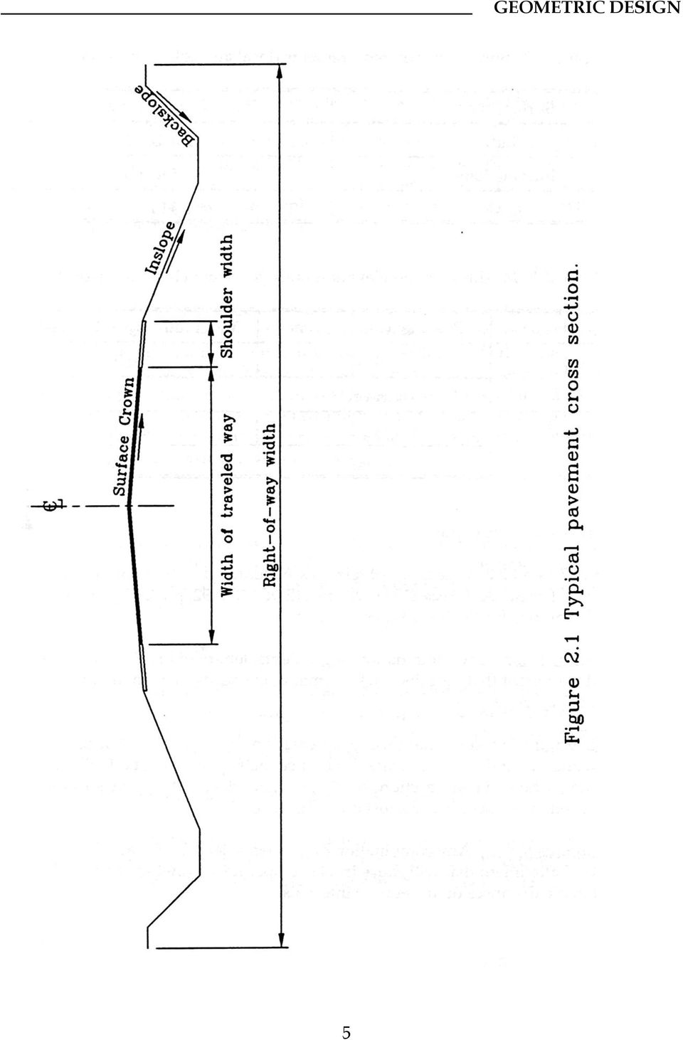
9 GEOMETRIC DESIGN 2. GEOMETRIC DESIGN 2.1. Introduction The geometric design guidelines presented in this section are adapted from the SDDOT Secondary & Off-System Road Plan agreement between the Federal Highway Administration (FHWA) and the South Dakota Department of Transportation, dated November 26, Where information on a certain topic was not available in the above reference, the AASHTO manual entitled A Policy on the Geometric Design of Highways and Streets (AASHTO 1990) was used. In general, the information contained in these two documents tends to agree very closely. This section outlines a set of guidelines for the geometric design of local and collector rural roads. Because there are no rural arterial roads under local jurisdiction in South Dakota, guidelines on rural arterials are omitted from this document. It is important to note that these are guidelines and not mandatory standards. More detailed information on the design of rural roads may be found in the SDDOT Secondary and Off-System Road Plan and the AASHTO Geometric Guide. The designer should make every effort to provide the best possible alignment, grade, adequate drainage, and sight distance consistent with the terrain, present and proposed development, and funds available to the agency. Please note that guidelines on signing and safety appurtenances are not included in this document. These guidelines are available from the SDDOT Office of Local Government Assistance ( ) and the South Dakota Transportation Technology Transfer (T 3 ) Service. The South Dakota T 3 Service has developed a document that summarizes the requirements of the Manual on Uniform Traffic Control Devices (MUTCD). This document is available to the counties of South Dakota Geometric Requirements The following 12 geometric-related items addressed in this document: Design speed. Roadway width. Vertical grades. Stopping sight distance. Pavement surface crown. Right-of-way width. Superelevation. Shoulder width. Minimum curve radius. Maximum degree of curvature. Vertical clearance. Inslope (foreslope). A summary of the requirements for each of these items is provided in Tables 2.1 through 2.4 and the paragraphs following. An illustration of several of the items is provided in Figure 2.1. Information on other geometric-related items can be found in 3
 was used.")
10 GEOMETRIC DESIGN 4

11 5 GEOMETRIC DESIGN
12 GEOMETRIC DESIGN Table 2.3. Surface crown requirements (local and collector roads). Surface type Rate of surface crown, % High 1.5 to 2.0 Intermediate 1.5 to 3.0 Low 2.0 to 6.0 Table 2.4. Maximum superelevation rates (local and collector roads). Rural road type Pavement surface type Maximum superelevation rate Local Paved 0.06 Gravel 0.12 Collector Paved 0.06 Gravel n\a the AASHTO Geometric Guide. In Tables 2.1 and 2.2, three types of terrain are identified level, rolling, and mountainous. The SDDOT Road Design Manual (SDDOT 1992, pp. 2-7) provides the following definitions for the three types of terrain: Level (flat) terrain: Any combination of gradients, length of grade, or horizontal or vertical alignment that permits trucks to maintain speeds that equal or approach the speeds of passenger cars. Rolling terrain: Any combination of gradients, length of grade, or horizontal or vertical alignment that causes trucks to reduce their speeds substantially below that of passenger cars on some sections of highway, but does not involve sustained crawl speed by trucks for any substantial distance. Mountainous terrain: Any combination of gradients, length of grade, or horizontal or vertical alignment that will cause trucks to operate at crawl speed for considerable distances or at frequent intervals. 6
 provides the following definitions for the three types of terrain: Level (flat) terrain: Any combination of gradients, length of grade, or horizontal or vertical alignment that permits trucks to")
13 GEOMETRIC DESIGN Design Speed Design speed is the maximum safe speed that can be maintained under favorable conditions and should be consistent with the speed a driver is likely to expect. Typically, the posted speed should be less than the design speed. Design speed influences a vehicle s stopping sight distance and side friction on curves. Lower design speeds are applicable to roads with winding alignment in rolling or mountainous terrain. Higher design speeds are applicable to roads in level terrain or where other environmental conditions are favorable Width of Roadway The roadway width is defined as the combined width of the traveled way (trafficked area) and the shoulders. The minimum width of traveled way for rural roads is 5.5 m (18 ft), and the minimum shoulder width is 0.6 (2 ft). These minimum values are to be increased based on road classification, design speed, and traffic levels. By South Dakota statute, the minimum total roadway width is 6.7 m (22 ft). If there is significant truck traffic and there is a possibility that the road will receive improvements, including additional gravel or an asphalt overlay, it is strongly suggested that a wider roadway width be used Vertical Grades The vertical grade of a roadway is defined as the ratio between the change in elevation over a change in length. Grades should be as level as practical, given the surrounding terrain. Adequate surface crown should be provided to drain water from the pavement surface Stopping Sight Distance The length of roadway that is visible ahead of the driver should be long enough to enable a vehicle traveling at the design speed to stop before reaching a stationary object in the road. Stopping sight distance is directly related to design speed, higher design speed requires a longer stopping sight distance Minimum Curve Radius/Maximum Degree of Curvature The allowable degree of curvature is determined from the design speed, superelevation, and side friction characteristics of the road in question. The degree of curvature is directly related to the curve radius by the following relationship: 7

14 GEOMETRIC DESIGN D = 5,729.6 R (Eq. 2.1) where D = Degree of curvature. R = Curve radius, ft Pavement Surface Crown Pavement surface crown, or cross slope, should be adequate to provide proper surface drainage. The surface crown for rural roads typically ranges from 1.5 to 6.0 percent, depending on the pavement surface type. A summary of surface crown requirements is provided in Table 2.3. High-type pavements retain structural integrity and do not ravel if placed on a stable subgrade. The smoothness characteristics and proper crown of the surface enable drivers to steer easily and maintain a proper path. On the other hand, low-type pavements with raveled or loose surfaces, such as gravel, require greater steering effort to maintain a correct path. The surface type should be provided commensurate with the design speed selected for the road Superelevation The maximum rates of superelevation usable on roadways are controlled by several factors, including pavement surface type, climate conditions, terrain conditions, and traffic usage. A superelevation rate of 0.12 may be used on low-volume gravel-surfaced roads to facilitate cross drainage; however, rates this high may cause higher travel speed, conducive to rutting and displacement of gravel. Superelevation rates greater than 0.06 should not be used for roads with paved surfaces (high- or intermediate-types) Right-of-Way (ROW) Width Right-of-way width adequate to accommodate the construction, proper drainage, and maintenance of the roadway should be obtained. A wide right-of-way permits construction of gentle slopes and widening or strengthening of the pavement as traffic increases Vertical Clearance Vertical clearance at underpasses should be at least 4.3 m (14 ft) over the entire roadway width. It is a good idea to add 150 mm (6 in) to this height to allow future 8

15 GEOMETRIC DESIGN pavement resurfacing. By South Dakota statute, the minimum vertical clearance is 4.6 m (15 ft) under railroads and 5.5m (18 ft) for utilities Inslope Inslopes should be as gentle as feasible. Gentle inslopes increase safety by providing maneuvering area in emergencies, are more stable than steep slopes, aid in establishing plant growth, and simplify maintenance work. The maximum rate of inslope depends on the stability of local soils as determined by investigation and local experience, as well as available right-of-way width. The steepest inslope that should be used is 2:1 on local rural roads and 3:1 on rural collector roads. 9

16 3. TYPICAL ROADWAY SURFACE TYPES TYPICAL ROADWAY SURFACE TYPES Typically, a rural road is constructed with the type of surface consistent with the nature and volume of the traffic it accommodates. The four road surface types that are typically constructed in South Dakota's roads are: Gravel-surfaced. Blotter (chip seal). Asphalt concrete. Portland cement concrete. A brief discussion of each pavement type is presented below Gravel-Surfaced Roads Gravel roads are referred to as low-type surfaces because they usually serve low traffic volumes. This surface type provides the lowest level of service. The basic structure of gravel roads consists of a gravel layer of adequate thickness and quality overlying the subgrade. The thickness of the gravel layer generally depends on traffic volume, quality of gravel available, and the existing soil or subgrade. Structurally, gravel-surfaced roads function as flexible pavements. Structural capacity is achieved by spreading the load over the weaker underlying soil (the subgrade). The basic principle in the thickness design of gravel roads is to provide an adequate thickness based on traffic volume and the strength of the subgrade such that the stress reaching the subgrade does not exceed the in-place strength of the subgrade. For most conditions, a minimum of 100 to 150 mm (4 to 6 in) of gravel is required Blotter (Chip Seal) Pavements A blotter-surfaced road is considered an intermediate-type road. A blotter road consists of a surface treatment placed on a granular base. The surface treatment consists of a uniform application of asphalt cement to a road surface, followed immediately by a layer of aggregate chips. The surface treatment may be as thin as 6 mm (0.25 in) or as thick as 25 mm (1 in), depending on the size of the aggregate chips and the number of surface treatment applications. On lightly traveled roads, blotters provide a relatively long-term, inexpensive pavement that does not dust, corrugate (washboard), or lose surface materials from the abrasive action of vehicle tires. However, on roads carrying heavier volumes of traffic (especially trucks), the blotter pavement provides only a comparatively short service life. 11

17 TYPICAL ROADWAY SURFACE TYPES 3.3. Asphalt Concrete Pavements Asphalt concrete (AC) pavements are considered to be high-type pavements and are intended to serve intermediate to high traffic volumes or heavy wheel loads. Conventional AC pavements are layered systems, typically consisting of an asphalt concrete surface placed on one or more layers of bound or unbound granular materials, which in turn are placed on the existing subgrade soil. The various layers of a conventional AC pavement consist of the following material types and typical thicknesses: AC layer that is 50 to 150 mm (2.0 to 6.0 in) thick. Aggregate (gravel) base course that is 150 to 300 mm (6.0 to 12.0 in) thick. Compacted subgrade. Figure 3.1 shows a typical cross section of a conventional AC pavement. The basic principle supporting the design and performance of such layered pavement systems is to provide higher quality (stronger) materials in the top layers, where the stresses from vehicle loads are high, and to use lower quality (weaker) materials in the lower pavement layers, where stress intensities are much lower. For example, in Figure 3.1 the surface course should have the highest strength and the subgrade the lowest strength. 12
 thick.")
18 TYPICAL ROADWAY SURFACE TYPES In a conventional AC pavement, the AC layer is intended to provide smooth rideability and good skid resistance, promote good pavement surface drainage, prevent moisture from infiltrating into the pavement structure, and protect the underlying base course layers from the high stresses that occur at the interface between the pavement surface and tires. Although the AC layer does provide some distribution of vehicle loads, the relative thinness of this layer limits its load-carrying capabilities. A majority of the load distribution occurs in the base course layer. Therefore, adequate layer thickness and material quality should be used in the base course layer to ensure that load-related stresses are sufficiently distributed and that the underlying subgrade is protected. The two primary load-related failure modes of AC pavements are alligator cracking and pavement rutting. AC alligator cracking occurs when excessive tensile strains develop at the bottom of the AC layer. This form of cracking can best be minimized by providing adequate AC thickness and good underlying support. AC pavement rutting typically results from excessive vertical stresses on top of the subgrade or excessive shear stresses in the aggregate (gravel) base course. Again, adequate pavement thickness (both AC and base course) can minimize this rutting. Rutting can also occur in the AC or base course layer as a result of increased material densification under traffic. However, this type of rutting can be minimized through proper material specification and construction control. Significant amounts of rutting and alligator cracking can be expected if heavy trucks are allowed to travel on under-designed pavements. Primary material- and AC mixture-related failure modes of AC pavements include asphalt stripping (separation of the asphalt from the aggregate), low-temperature cracking, and asphalt bleeding. These forms of deterioration generally occur as a result of poor material selection or improper AC mixture design. However, improper construction techniques, such as improper compaction, can cause or worsen these conditions. Although these forms of AC pavement deterioration are important to overall pavement performance, this guide focuses primarily on load-related distresses. Full-depth AC pavements consist of one or more layers of AC placed directly on the subgrade or improved subgrade. In the State of South Dakota, poor pavement performance has been associated with this type of AC pavement. Therefore, the South Dakota Department of Transportation does not encourage the construction of full-depth AC pavements. 13

19 TYPICAL ROADWAY SURFACE TYPES 3.4. Portland Cement Concrete Pavements PCC Pavement Types Portland cement concrete (PCC) pavements are referred to as rigid pavements. The PCC is typically placed on an aggregate (gravel) base layer. A typical cross section of a PCC pavement is presented in Figure 3.2. The types of concrete pavement that are typically constructed on rural roads include: Jointed plain concrete pavement (JPCP). Jointed reinforced concrete pavement (JRCP). Continuously reinforced concrete pavement (CRCP) is another type of PCC pavement, but CRCP is rarely used on rural, low-volume roads. The primary differences between JPCP and JRCP are associated with the use of slab reinforcement and the transverse joint spacing. JPCP has no reinforcement and a short (typically 4.6 m [15 ft ] or less) transverse joint spacing. JRCP has reinforcing steel in the PCC to hold tightly together any cracks that form. Typically, the joint spacing in a JRCP is much greater (up to 15 m [50 ft]) than in a JPCP. Therefore, fewer joints are required in a JRCP, but the trade-off is the cost of the reinforcement. Cracking in concrete pavements is caused by the combined effects of temperature and moisture changes and the effect of wheel loads. Transverse and longitudinal joints are provided in concrete pavements to control the locations of the cracking. 14
 is another type of PCC pavement, but CRCP is rarely used on rural, low-volume roads.")
20 TYPICAL ROADWAY SURFACE TYPES Load transfer across PCC joints is very important in reducing stresses at the joints. Aggregate interlock across a joint is typically the only form of load transfer in PCC rural roads, although this frequently results in joint faulting. Load transfer devices, such as dowel bars, can also be used to provide additional load transfer across a PCC joint. However, use of load transfer devices in thin PCC (less than 200-mm [8-in] thick slabs) can result in severe joint deterioration due to high stress concentrations around the devices. Because of the shortened life of under-designed PCC pavements and their costly rehabilitation, extreme caution should be used in constructing PCC slabs that are less than 200 mm (8.0 in) thick. Also, the SDDOT Office of Local Government Assistance ( ) should be consulted regarding aggregate sources, as some aggregates will contribute to premature PCC deterioration Function of the Various Layers in a PCC Pavement The PCC surface layer performs two primary functions it provides a smooth riding surface and significant load distribution over a relatively large area. In a properly designed PCC pavement, the vertical stress levels in the layers below the PCC are only a small fraction of those applied on the pavement surface. Due to the tremendous stiffness of the PCC layer (with respect to the underlying base and subgrade layers) the PCC layer provides a vast majority of the pavement's load-carrying capabilities. Therefore, the most effective way to reduce stresses (and hence, reduce cracking) in a PCC pavement is through increased PCC thickness. Increases in PCC strength or underlying base/subgrade support only have a minimal effect in reducing PCC stresses. However, this does not preclude the importance of the use of good bases and subgrades. A base in a PCC pavement is provided directly under the concrete surfacing. Base material may either be of natural selected aggregate (gravel) or stabilized soil with emphasis on a minimum amount of fine-grained materials. One of the primary functions of a base is to prevent the pumping of these fine-grained subgrade materials from beneath the PCC layer. When pumping occurs, corner breaks, joint faulting, and slab cracking can be expected. The simultaneous existence of three factors heavy traffic loads, pumpable fine-grained soils, and excessive subgrade moisture can result in the pumping of fines. Where these three critical factors prevail, the use of a base under the PCC is highly encouraged. Other functions of PCC pavement bases include: Provide improved load transfer at pavement joints. Provide uniform support for the pavement. Provide a firm improved platform for pavement construction. Provide a drainage layer for water entering the pavement system. The typical base layer thickness on a rural PCC pavement is 100 to 150 mm (4 to 6 in). 15
 can result in severe joint deterioration due to high stress concentrations around the devices.")
21 4. GRAVEL ROAD DESIGN AND REPAIR 4.1. Gravel Road Repair Options GRAVEL ROAD DESIGN AND REPAIR Gravel surfacing is common on low-volume rural roads. If properly constructed and maintained, a gravel-surfaced road provides a low-cost structure that can more than adequately support low-volume traffic conditions. However, proper maintenance is the key to the performance of this roadway surface type. Typically, in the maintenance and repair of a gravel-surfaced road, the following seven distresses/conditions must be addressed (Eaton and Beaucham 1992): Improper cross section. A properly crowned gravel pavement should have 100 to 150 mm (4.0 to 6.0 in) of crown, or slope, from its center to the edge. Inadequate roadside drainage. Corrugations. Dust. Potholes. Ruts. Loose aggregate. Each of these seven distresses has three severity levels low, medium, and high (Eaton and Beaucham 1992). Descriptions of the seven distresses and illustrations of the three severity levels for each distress are provided in the Rural Road Condition Survey Guide. The types of repairs and maintenance that are recommended for a gravel-surfaced road are related to the types and severities of distresses evident in the pavement. A summary of the recommended gravel-surfaced roadway maintenance and repair options, along with the distress type and severity each addresses, is provided in Table 4.1. An illustration of the relationship between gravel road condition and the corresponding repair method(s) is provided in Figure
22 GRAVEL ROAD DESIGN AND REPAIR Table 4.1. Suggested gravel road repair alternatives (Eaton and Beaucham, 1992). Distress type Improper gravel road surface crown Improper roadside drainage Distress severity Low Medium High Low Medium High Typical repair techniques Blade surface of roadway. Blade surface or blade surface and add material (water and aggregate), then recompact. Cut to subgrade, add aggregate, shape, add water, and compact. Clean ditches. Clean out culverts. Reshape, construct, and improve inslopes of ditches. Eliminate secondary ditches. Regrade ditches, construct special ditch grade, and raise the ditch grade line. The installation of larger culverts, ditch dams, rip rap, geotextiles, or underdrains may also be necessary. Corrugations Low Blade surface. Medium High Blade surface or blade surface and add material (aggregate and water), then compact. Cut to subgrade, add new aggregate (or alter gradation), shape, add water, and compact. Dust stabilization Low Add water to surface. Medium High Add a stabilizer (e.g., calcium chloride) to the surface. Increase stabilizer use or Cut to subgrade, add stabilizer, water, and compact or Cut to subgrade, add aggregate and stabilizer, shape, water, and compact. or Upgrade to a paved surface. 18
23 GRAVEL ROAD DESIGN AND REPAIR Table 4.1.Suggested gravel road repair alternatives (continued). Distress type Distress severity Typical repair techniques Potholes Low Blade surface of roadway. Medium High Blade surface or blade surface, add material (water, aggregate, or mix of calcium chloride and crushed gravel), and compact. Cut to subgrade, add aggregate, shape, add water, and compact. Ruts Low Blade surface of roadway. Medium High Blade surface or blade surface, add material (water, aggregate, or mix of calcium chloride and crushed gravel), and compact. Cut to subgrade, add aggregate, shape, add water, and compact. Loose aggregate Low Blade surface. Medium High Blade surface or blade surface, add material (restore gradation and water), and compact. Cut to subgrade, add new aggregate, shape, add water, and compact Typical Gravel Road Repair Techniques Surface Blading As illustrated in Table 4.1, blading of the gravel surface is periodically necessary to restore proper pavement crown and remove minor corrugations, potholes, and ruts. When blading a gravel road (especially in the spring or when adequate moisture is present), the top 50 to 100 mm (2.0 to 4.0 in) of gravel should be scarified and reshaped to provide the necessary crown and to eliminate the surface irregularities. When dry conditions exist, only light blading should be done, and care should be taken not to disturb any crust that exists. 19
24 GRAVEL ROAD DESIGN AND REPAIR 20
25 GRAVEL ROAD DESIGN AND REPAIR Regraveling Over time, the gravel layer thickness becomes significantly reduced due to dusting and the pushing of loose gravel to the shoulders and ditches. In these instances, it is necessary to add new gravel to the roadway surface. The aggregate material, whether for repair of an existing gravel-surfaced road or for a new gravel-surfaced road, should comply with the gradation and durability requirements outlined in section 882, Aggregates for Granular Bases and Surfacing, of the SDDOT Standard Specifications for Road and Bridge Construction. Regraveling thicknesses are typically in the range of 75 to 150 mm (3 to 6 in) Dust Control Rolling and compacting of a new gravel surface will help to maintain a tight and impervious surface that has few dusting problems. When dusting does occur, it can be minimized through the application of water or a stabilizing agent (calcium chloride or magnesium chloride) to the surface. The water will only provide a short-term solution and is seldom feasible except in special situations on short sections of road, whereas the stabilizing agent provides a more long-term solution. Section 205, Dust Control, of the SDDOT Standard Specifications for Road and Bridge Construction, provides specifications for the application of either calcium chloride or magnesium chloride (magwater). A summary of these specifications is provided below. 1. The dust control chlorides should be uniformly applied under pressure in liquid form by mechanical equipment. The rate of application should be 0.65 kg/m 2 (1.2 lb/yd 2 ) of pavement surface. This weight should be the anhydrous (free of water) weight of the chloride solution. The chloride material should comply with section 891, Dust Oil and Dust Control Chlorides, of the SDDOT Standard Specifications for Road and Bridge Construction. 2. The chloride should be blended into the top 25 to 50 mm (1 to 2 in) of the gravel surface. 3. The pavement surface should be tightly compacted. The addition of water may be necessary in order to adequately compact the material Cleaning Ditches Roadside ditches play a substantial role in providing adequate drainage for a gravel road. It is important that the roadside ditches be properly shaped and sloped and remain free of vegetation and debris. The ditch bottom should always be below the subgrade elevation, and the longitudinal grade of the ditch should be 1 percent or more, if possible, to promote good drainage. 21
26 GRAVEL ROAD DESIGN AND REPAIR Ditches must periodically be cleaned to restore drainage. This work is typically performed with a motor grader. However, on some roads either the right-of-way is too limited or the ditch slope is too steep to allow the use of a motor grader. In these instances, an articulated, boom-mounted bucket can be used. Erosion of ditches can also be a problem. To prevent erosion of ditches, one of the following techniques can be used: Lining the ditch with a geotextile and rock. Building ditch checks (dams) that reduce the velocity of the flow in the ditch. Letting grass grow in the bottom of the ditch. Widening the ditch to shallow the flow and reduce the velocity of the water flow New or Reconstructed Gravel Roads The thickness of new aggregate-surfaced roads typically ranges from 150 to 375 mm (6 to 15 in). A gravel thickness of 75 to 150 mm (3 to 6 in) is very typical on South Dakota s rural gravel-surfaced roads. The gravel layer thickness necessary is primarily dependent on the level of heavy truck traffic that uses the roadway and the strength of the subgrade. The desired level of gravel road performance is also a factor in determining the necessary gravel layer thickness. Obviously, the greater the desired level of performance the thicker the gravel layer should be. Guidelines for selecting the appropriate gravel layer thickness are provided in table 4.2. These thicknesses were calculated using the design procedures presented in the 1993 American Association for State and Highway Transportation Officials (AASHTO) Guide for the Design of Pavement Structures. Table 4.2 identifies four truck traffic ranges and three subgrade strength ranges. These designs are based on a 5-year design life and 60 mm (2.5 in) of allowable rutting. The suggested gravel layer thickness presented in Table 4.2 should be used as guidelines. Local experience and expertise should also be considered when selecting a gravel layer thickness. Also, please consult the SDDOT Office of Local Government Assistance ( ) for assistance in the design of a gravel road for a route that carries more than 50 heavy trucks per day Typical Gravel Road Repair Frequency Unlike paved roads, gravel-surfaced roads require continual maintenance and repair efforts. On paved roads, maintenance activities typically occur on an annual or 22
27 GRAVEL ROAD DESIGN AND REPAIR biannual basis. On gravel-surfaced roads, maintenance activities are typically performed weekly, every few weeks, or every few months. Based on interviews with several South Dakota county highway agencies, the maintenance schedule outlined in Table 4.3 is commonly used. Table 4.2. Suggested gravel layer thicknesses for new or reconstructed rural roads. Estimated daily no. of heavy trucks Subgrade support condition 1 Suggested minimum gravel layer thickness, mm (in) 0 to 5 Low 165 (6.5) Medium 140 (5.5) High 115 (4.5) 5 to 10 Low 215 (8.5) Medium 180 (7.0) High 140 (5.5) 10 to 25 Low 290 (11.5) Medium 230 (9.0) High 180 (7.0) 25 to 50 Low 370 (14.5) Medium 290 (11.5) High 215 (8.5) Notes. 1 Low subgrade support: average CBR < 3 percent; medium subgrade support: 3 percent < average CBR < 10 percent; high subgrade support: average CBR > 10 percent. 2 CBR = California Bearing Ratio of the in-place subgrade soils. Methods of estimating CBR are discussed in section 7 of this document. 23
28 GRAVEL ROAD DESIGN AND REPAIR Table 4.3. Gravel road maintenance guidelines. ADT ADTT Terrain Gravel frequency, years Blading frequency, per month > 50 < 50 High Low Low Level 4 4 Rolling 5 4 Mountainous 4 4 Level 7 3 Rolling 7 3 Mountainous 6 3 Level 5 2 Rolling 7 2 Mountainous 6 2 ADT = average daily traffic. ADTT = average daily truck traffic. 24
29 5. FLEXIBLE PAVEMENT DESIGN AND REPAIR 5.1. Flexible Pavement Repair Options FLEXIBLE PAVEMENT DESIGN AND REPAIR This section identifies the techniques that are typically used to repair flexible pavements in each of the seven pavement condition categories listed below. For the purpose of this guide, flexible pavements include both AC and blotter pavements. Condition Rating Category Value Range Excellent 100 to 86 Very Good 85 to 71 Good 70 to 56 Fair 55 to 41 Poor 40 to 26 Very Poor 25 to 11 Failed 10 to 0 The intent of this section is to identify the different pavement repair techniques and briefly discuss when application of each of the repair techniques is appropriate. Discussion of specific details of each of the identified repair techniques is provided later in this section. The identified repair techniques primarily address pavement-related deterioration and deficiencies. The techniques do not specifically address geometricrelated deficiencies, although in some instances both concerns will be addressed (i.e., correction of AC rutting and insufficient pavement cross slope through partial depth replacement of the AC layer). As the condition of a flexible pavement changes, so does the pavement's repair needs. For flexible pavements in excellent condition, minimal amounts of crack sealing are all that is typically needed. However, for significantly deteriorated flexible pavements, much more expensive repairs, such as full-depth patching, AC overlays, or complete reconstruction, may be necessary. An illustration of the relationship between flexible pavement condition and the corresponding repair method(s) is provided in Figure 5.1. As seen in this figure, a delay in repairing a pavement can result in significantly greater repair requirements. If not properly maintained, a pavement can deteriorate to a condition where low-cost maintenance activities are no longer effective. 25
30 FLEXIBLE PAVEMENT DESIGN AND REPAIR 26
31 FLEXIBLE PAVEMENT DESIGN AND REPAIR Flexible Pavements in Excellent Condition (Rating Value of 86 to 100) Flexible pavements in excellent condition typically consist of newly-constructed or well-maintained pavements that are in sound structural condition. Typically, the only distresses (if any) in a flexible pavement in excellent condition are minor hairline cracks and minor depressions. Repairs to flexible pavements in excellent condition typically consist of maintenance activities, such as crack sealing. When sealing cracks in a flexible pavement, it is recommended that all visible cracks be routed and sealed. Leaving cracks unsealed, especially as they become wider, can lead to water infiltration and accelerated pavement deterioration Flexible Pavements in Very Good Condition (Rating Value of 71 to 85) The surface of a flexible pavement with a condition rating of 71 to 85 may be partially oxidized or weathered. Also, low- to medium-severity cracking may be present. However, the cracks are generally very tight. Crack sealing is also the primary form of maintenance performed on flexible pavements in very good condition. As previously noted, it is recommended that all visible cracks be routed and sealed when performing crack-sealing operations. In addition to crack sealing, application of a surface treatment may be appropriate if the pavement surface is substantially weathered or oxidized. Also, full-depth patching should be performed in alligator-cracked and potholed areas Flexible Pavements in Good Condition (Rating Value of 56 to 70) Flexible pavements in good condition typically exhibit noticeable amounts of surface oxidation and raveling. Transverse and longitudinal cracks are typically between 6 and 13 mm (0.25 and 0.5 in) wide. Alligator cracking may begin to be present in the wheelpaths, and rutting of the wheelpaths is becoming more pronounced. Maintenance and minor rehabilitation activities are typically required on flexible pavements in good condition. Crack sealing should still be performed, and alligatorcracked and potholed areas should be patched full-depth. If surface oxidation or raveling is significant, a surface treatment may be appropriate. If rutting is a problem, placement of a thin (38 to 50 mm [1.5 to 2.0 in]), nonstructural AC overlay is recommended. 27
32 FLEXIBLE PAVEMENT DESIGN AND REPAIR Flexible Pavements in Fair Condition (Rating Value of 41 to 55) Pavement deterioration is becoming more advanced in flexible pavements in fair condition. Block cracking is common, and weathering of the AC surface is quite noticeable. The cracks are generally greater than 13 mm (0.5 in) wide, and deterioration of the cracks is prevalent. Rutting in the wheelpaths is more pronounced and may be over 13 mm (0.5 in) deep. Areas of medium- to high-severity alligator cracking may also be present in the wheelpaths. For flexible pavements in fair condition, minor to major rehabilitation is typically required. The appropriate form of repair is highly dependent on the types of distresses present. Scenarios of different pavement conditions and suggested repairs are discussed below. Scenario 1: If the pavement distresses are not predominantly load related (e.g., minimal amounts of alligator cracking and rutting) and primarily consist of longitudinal, transverse, and block cracking, an appropriate form of repair includes sealing cracks, full-depth patching of any alligator-cracked and potholed areas, and placement of a thin (38 to 50 mm [1.5 to 2.0 in]) AC overlay. Partial-depth removal of the AC layer may be necessary to accommodate grade constraints, such as overpass clearance requirements, that cannot be overlaid. Scenario 2: If only minor amounts of alligator cracking are evident and the AC surface is either significantly oxidized or rutted, repair should include the partial-depth removal (milling) and replacement of the AC surface. Scenario 3: If alligator cracking is evident over much of the pavement, especially the wheelpaths, complete removal and replacement of the AC layer is suggested. If the alligator cracking occurred over a typical pavement service life (20 years or more) and similar traffic conditions are expected, placement of a similar thickness of AC is most likely sufficient. However, if the alligator cracking occurred over a shorter time period or substantially higher truck volumes are anticipated, a greater thickness of AC is needed. If the base thickness is inadequate, pulverizing the in-place AC and combining it with the upper portion of the underlying base course before placing a new AC wearing course should be considered Flexible Pavements in Poor Condition (Rating Value of 26 to 40) Flexible pavements with this condition rating are badly deteriorated. Severe alligator cracking is common, with pieces of AC missing and potholes present. Rutting is also common on flexible pavements in this condition, and the pavement's rideability is typically poor. 28
33 FLEXIBLE PAVEMENT DESIGN AND REPAIR Flexible pavements in this condition generally require major rehabilitation. The repair techniques discussed in Scenario 3 are typically appropriate. However, if significant quantities of the underlying base and subgrade require stabilization prior to placement of the new AC layer(s), it may be more appropriate to perform complete reconstruction. The actual percentage of base course/subgrade stabilization at which total reconstruction becomes more cost-effective will vary from county to county, depending on actual construction costs Flexible Pavements in Very Poor and Failed Condition (Rating Value of 0 to 25) Flexible pavements in either very poor or failed condition have reached a condition level in which traffic operation is difficult. Potholes and alligator cracking are extensive, and rut depths may exceed 20 mm (0.75 in). Complete reconstruction is the only appropriate means of pavement repair Flexible Pavement Repair Techniques Crack Sealing The purpose of sealing cracks in a flexible pavement is to minimize the amount of water entering the pavement system through the pavement surface and to minimize the amount of deterioration (spalling, additional cracking) along the edges of cracks. Procedures: There are many methods of sealing (or filling) cracks in a flexible pavement. An illustration of some of these methods is provided in Figure 5.2. One of the easiest and cheapest methods is to simply blow debris out of the cracks with an air compressor and fill the cracks with a suitable hot-pour asphalt sealant (method A in Figure 5.2). Unfortunately, use of this method typically results in poor crack sealant performance. More elaborate methods of crack sealing can include crack routing, backer rod placement, use of high-quality sealant materials, and placement of a sealant overband. These advanced methods obviously cost more initially, but the increased sealant performance and life generally offset the increase in initial cost. The SDDOT currently specifies the use of the standard recessed band-aid method (method E) for AC-surfaced pavements. SDDOT experience is that the sealant configuration has performed as well as any method in the State of South Dakota. However, in locations of heavy pedestrian use or turning vehicles, placement of the overband is not recommended. During summer months, the sun-heated sealant will be picked up by pedestrians and turning vehicles. Therefore, the use of the standard reservoir-and-flush configuration (method D) is recommended. The results of a recent national study on flexible pavement joint sealants indicated that both methods D and E exhibited very good performance characteristics. Therefore, 29
34 FLEXIBLE PAVEMENT DESIGN AND REPAIR 30
35 FLEXIBLE PAVEMENT DESIGN AND REPAIR unless the sealant is only needed to perform for 1 year or less (e.g., an overlay is to be placed over the pavement in the very near future), use of the standard reservoir-andflush configuration is recommended. The recommended procedures for sealing cracks in AC-surfaced pavements are provided in the SDDOT Performance Standard Function 2112, Rout and Seal Cracks. Although not outlined in this standard, it is common practice in the State of South Dakota to seal all visible cracks in the pavement surface. A summary of the procedures outlined in Function 2112 is provided below. As previously discussed, the placement of a sealant overband (specified in Function 2112) is not recommended for areas of high pedestrian traffic or turning vehicles. 1. Cracks should be routed with a star bit router or random crack saw. The routed channel should be 20 mm (0.75 in) wide and 20 mm (0.75 in) deep. Cracks greater than 20 mm (0.75 in) wide during the summer months will not require routing but should be thoroughly cleaned to a depth equal to the crack width. 2. An inert compressible material (e.g., backer rod) should be inserted along the bottom of cracks deeper than 20 mm (3/4 in). The material should be positioned such that the sealant depth will be equal to the crack width. 3. The channel shall be thoroughly cleaned of all dust, dirt, and loose materials with oil-free compressed air immediately before sealant application. 4. The channel shall be overfilled with sealant and shall be squeegeed with a U- shaped device that treats the roadway surface 25 to 75 mm (1 to 3 in) on each side of the channel. 5. In areas of high pedestrian traffic or turning vehicles, the channel shall be filled with sealant so that the sealant is flush with the pavement surface. For blotter pavements, a less elaborate means of sealing cracks is recommended. Crack routing is generally not effective on these pavements; the routing operation typically chips the surface treatment. Therefore, on blotter pavements, either method A or method C is recommended, and method C is preferred. For both of these methods, it is imperative that the crack be thoroughly cleaned with oil-free compressed air. Materials: For sealing cracks in flexible (blotter and AC-surfaced) pavements, the SDDOT requires the use of a rubberized asphalt sealant (hot-pour) meeting the requirements of the American Society for Testing and Materials (ASTM) Test Designation D Several manufacturers produce sealants that meet these requirements. 31
APPENDIX B. I. Background Information
 APPENDIX B GUIDELINES FOR IDENTIFYING AND REPAIRING LOCALIZED AREAS OF DISTRESS IN AC PAVEMENTS PRIOR TO CAPITAL PREVENTIVE MAINTENANCE OR REHABILITATION REPAIRS I. Background Information A. AC Pavement
Chapter 7: Pavement Rehabilitation 7-1 Asphalt Pavement Overlays 7-1 Surface Preparation Methods 7-2 Concrete Pavement Preparation 7-3 Recycling
 7-1 Asphalt Pavement Overlays 7-1 Surface Preparation Methods 7-2 Concrete Pavement Preparation 7-3 Recycling Asphalt Pavements 7-7 Chapter 7 Pavement Rehabilitation Pavement rehabilitation can be accomplished
Rehabilitation Strategies for Bonded Concrete Overlays of Asphalt Pavements
 University of Pittsburgh Rehabilitation Strategies for Bonded Concrete Overlays of Asphalt Pavements Authors: J. M Vandenbossche S. Sachs August 2013 1. Introduction Bonded concrete overlays of asphalt
SECTION III-06 Surfacing Page 1 Revised 3/2/10. See the DESIGN GUIDELINES in Section I-06 for requirements for cross slope of the roadway.
 Page 1 Revised 3/2/10 See the DESIGN GUIDELINES in Section I-06 for requirements for cross slope of the roadway. For New/Reconstruction projects: The cross slope of the driving lanes range from 1.5% to
The AASHO Road Test site (which eventually became part of I-80) at Ottawa, Illinois, was typical of northern climates (see Table 1).
 at Ottawa, Illinois, was typical of northern climates (see Table 1).") Página 1 de 12 AASHO Road Test The AASHO Road Test, a $27 million (1960 dollars) investment and the largest road experiment of its time, was conceived and sponsored by the American Association of State
Página 1 de 12 AASHO Road Test The AASHO Road Test, a $27 million (1960 dollars) investment and the largest road experiment of its time, was conceived and sponsored by the American Association of State
September 1, 2003 CONCRETE MANUAL 5-694.900 CONCRETE PAVEMENT REHABILITATION 5-694.900
 September 1, 2003 CONCRETE MANUAL 5-694.900 5-694.901 GENERAL CONCRETE PAVEMENT REHABILITATION 5-694.900 Concrete Pavement Rehabilitation is an extremely valuable tool of the Minnesota Department of Transportation
OHIO ASPHALT PAVING CONFERENCE
 OHIO ASPHALT PAVING CONFERENCE 38 th Annual Conference Wednesday, 2/6/2013 Fawcett Center Campus of The Ohio State University 2400 Olentangy River Road Columbus, Ohio 43210 REHAB STRATEGIES FOR LOCAL
Chapter Forty-seven. RURAL TWO-LANE/MULTILANE STATE HIGHWAYS (New Construction/Reconstruction) BUREAU OF DESIGN AND ENVIRONMENT MANUAL
 BUREAU OF DESIGN AND ENVIRONMENT MANUAL") Chapter Forty-seven RURAL TWO-LANE/MULTILANE STATE HIGHWAYS (New Construction/Reconstruction) BUREAU OF DESIGN AND ENVIRONMENT MANUAL Illinois RURAL TWO-LANE/MULTILANE STATE HIGHWAYS December 2009 2 Illinois
Chapter Forty-seven RURAL TWO-LANE/MULTILANE STATE HIGHWAYS (New Construction/Reconstruction) BUREAU OF DESIGN AND ENVIRONMENT MANUAL Illinois RURAL TWO-LANE/MULTILANE STATE HIGHWAYS December 2009 2 Illinois
State of Illinois Department Of Transportation CONSTRUCTION INSPECTOR S CHECKLIST FOR STORM SEWERS
 State of Illinois Department Of Transportation CONSTRUCTION INSPECTOR S CHECKLIST FOR STORM SEWERS While its use is not required, this checklist has been prepared to provide the field inspector a summary
Pavement Patching Repair for AC and PCC Pavement Surfaces. Vern Thompson www.crafco.com
 Pavement Patching Repair for AC and PCC Pavement Surfaces Vern Thompson www.crafco.com Overview and Objective New Methods For Pavement Patching-Overview What are they How they are applied New Methods Secti
Road Rehabilitation and Reconstruction Using AutoCAD Civil 3D
 Road Rehabilitation and Reconstruction Using AutoCAD Civil 3D Contents Introduction... 3 Introduction to Corridor Targets... 3 Surface Targets... 4 Width and Offset Targets... 5 Elevation or Slope Targets...
CAPITAL PREVENTIVE MAINTENANCE
 CAPITAL PREVENTIVE MAINTENANCE 2003 EDITION April 8, 2010 CONSTRUCTION AND TECHNOLOGY DIVISION Attention Manual Holders This manual is to remain with the assigned user. If the user relocates within the
Joint Rehabilitation. Driving Forces for Concrete Pavement Joint Repairs
 Long Life Concrete Pavement Joint Performance Joint Rehabilitation Gary Fick, Trinity Construction Management Services, Inc. Representing the National CP Tech Center Driving Forces for Concrete Pavement
Transportation Infrastructure Asset Management
 2015 NW Region TTAP& BIA Symposium Transportation Infrastructure Asset Management March, 2015 Happy Longfellow, PE hlongfellow@parametrix.com (206) 394-3649 ASSET MANAGEMENT OVERVIEW What? Why? How? Inventory
4-02 Gravel Base. 4-04 Ballast and Crushed Surfacing
 Chapter 4 Bases 4-02 Gravel Base GEN 4-02.1 General Instructions Gravel Base is typically used in the construction of the roadway section and provides support for the pavement. For the pavement to provide
2011 NACE Conference by. Ken Skorseth SDLTAP Program Manager
 2011 NACE Conference by Ken Skorseth SDLTAP Program Manager Paving or constructing asphalt surface treatments when asphalt prices were low. May not have been justified based on traffic, but it bought political
Pavement Surface Evaluation and Rating. Manual RATING RATING RATING PASER RATING. Concrete Roads
 Pavement Surface Evaluation and Rating PASER Manual Concrete Roads RATING 10 RATING 7 RATING 4 RATING 1 Contents Introduction 2 Rigid pavement performance 2 Pavement conditions and defects 3 Evaluation
738-B-297 POLYMERIC CONCRETE BRIDGE DECK OVERLAY. (Adopted 02-20-14)
") POLYMERIC CONCRETE BRIDGE DECK OVERLAY (Adopted 02-20-14) Description The polymeric concrete bridge deck overlay shall consist of an epoxy polymer that acts together with special aggregate to form an overlay
POLYMERIC CONCRETE BRIDGE DECK OVERLAY (Adopted 02-20-14) Description The polymeric concrete bridge deck overlay shall consist of an epoxy polymer that acts together with special aggregate to form an overlay
CID STREET INFRASTRUCTURE ASSESSMENT
 ABSTRACT An evaluation of the street infrastructure in Foxberry Estates Phase 1, including pavement condition, verification of construction techniques, and subgrade quality. Recommendations and costs for
Safe & Sound Bridge Terminology
 Safe & Sound Bridge Terminology Abutment A retaining wall supporting the ends of a bridge, and, in general, retaining or supporting the approach embankment. Approach The part of the bridge that carries
Local Road Assessment and Improvement Drainage Manual
 Local Road Assessment and Improvement Drainage Manual Donald Walker, T.I.C. Director, author Lynn Entine, Entine & Associates, editor Susan Kummer, Artifax, design Transportation Information Center University
Session 7: Retrofitted Edge Drains 7.1
 Session 7: Retrofitted Edge Drains 7.1 Learning Outcomes 1. List benefits of drainage 2. List components of edge drain systems 3. Describe recommended installation procedures 4. Identify typical construction
CHAPTERS 600 670 PAVEMENT ENGINEERING CHAPTER 600 GENERAL ASPECTS
 HIGHWAY DESIGN MANUAL 600-1 May 7, 2012 CHAPTERS 600 670 PAVEMENT ENGINEERING CHAPTER 600 GENERAL ASPECTS Topic 601 - Introduction Pavement engineering involves the determination of the type and thickness
KENTUCKY TRANSPORTATION CABINET POLICY FOR FEDERALLY FUNDED PAVEMENT REHABILITATION AND PREVENTATIVE MAINTENANCE PROJECTS
 KENTUCKY TRANSPORTATION CABINET POLICY FOR FEDERALLY FUNDED PAVEMENT REHABILITATION AND PREVENTATIVE MAINTENANCE PROJECTS I. GENERAL The following policy shall apply when the intent of the project is to
DRAFT MAINTAINING HOUSTON S STREETS REPAIR, REHABILITATION, RECONSTRUCTION. Using the Full Range of Tools for a Challenging Job
 MAINTAINING HOUSTON S STREETS REPAIR, REHABILITATION, RECONSTRUCTION Using the Full Range of Tools for a Challenging Job Report To: TTI Committee May 13, 2014 1 Pavement Management - Suggested Treatments
Porous Pavement Alternatives Cost Analysis
 Porous Pavement Alternatives Cost Analysis Prepared by Century West Engineering for Metro This cost analysis compares the construction costs of six different types of pavement for three different scenarios.
Construction Specifications for Keyhole Pavement Coring and Reinstatement
 F I N A L Construction Specifications for Keyhole Pavement Coring and Reinstatement Gas Technology Institute 1700 S. Mount Prospect Rd. Des Plaines, Illinois 60018 www.gastechnology.org Version 13 October
Pavement Rehabilitation Selection Rehabilitation Techniques
 Pavement Rehabilitation Selection Rehabilitation Techniques Bituminous Pavement Rehabilitation Techniques Overlays Bituminous Concrete Pre-overlay Treatments Mill and Overlay Mill and Inlay Recycling Options
Why Maintain Your Asphalt?
 Asphalt Maintenance Why Maintain Your Asphalt? Asphalt pavement is basically sand, gravel and glue. The glue used to keep the sand and gravel together is asphalt, a heavy by-product of oil refining. While
SPECIFICATION FOR CONSTRUCTION OF UNBOUND GRANULAR PAVEMENT LAYERS
 TNZ B/02:2005 SPECIFICATION FOR CONSTRUCTION OF UNBOUND 1. SCOPE This specification shall apply to the construction of unbound granular pavement layers. The term pavement layer shall apply to any layer
C. Section 014510 TESTING LABORATORY SERVICE.
 SECTION 014500 QUALITY CONTROL PART 1 GENERAL 1.01 RELATED REQUIREMENTS A. Drawings and General Provisions of Contract, including General and Special Conditions and other Division 1 Specification Sections,
Performance of Edge Drains in Concrete Pavements in California
 Performance of Edge Drains in Concrete Pavements in California Biplab B. Bhattacharya, 1 Michael P. Zola, 2 Shreenath Rao, 3 Karl Smith, 4 Craig Hannenian 5 ABSTRACT The California Department of Transportation
SECTION 311 PLACEMENT AND CONSTRUCTION OF CEMENT TREATED SUBGRADESOIL CEMENT BASE COURSE
 PLACEMENT AND CONSTRUCTION OF CEMENT TREATED SUBGRADESOIL CEMENT BASE COURSE 311.1 DESCRIPTION: This item shall consist of a cement treated subgrade base course composed of a mixture of local soil, portland
CONCRETE REPAIR GUIDELINES. Concrete repairs can be broken down into four basic types, plus special repairs and planing.
 CONCRETE REPAIR GUIDELINES Concrete repairs can be broken down into four basic types, plus special repairs and planing. Note: It is recommended that investigation into soundness of pavement be performed
DISTRESS IDENTIFICATION MANUAL. for the Long-Term Pavement Performance Program
 DISTRESS IDENTIFICATION MANUAL for the Long-Term Pavement Performance Program PUBLICATION NO. FHWA-RD-03-031 JUNE 2003 In 1987, the Strategic Highway Research Program began the largest and most comprehensive
Pavement Rehabilitation Using Hot Mix Asphalt. - National Perspective -
 Pavement Rehabilitation Using Hot Mix Asphalt - National Perspective - Rehabilitation Process Evaluate Existing Pavement and Conditions Evaluate Options Construct Project Monitor Performance Evaluate Existing
Advancements in GPR for a Sustainable Tomorrow
 Advancements in GPR for a Sustainable Tomorrow Shawn Lapain, BSc. E., EIT Pavement Specialist Applied Research Associates Inc. 5401 Eglinton Avenue West, Suite 105, Toronto, ON, Canada, M9C 5K6 Tel: 416-621-9555,
Impacts of Increased Loading Due to Heavy Construction Traffic on Thin Pavements
 Impacts of Increased Loading Due to Heavy Construction Traffic on Thin Pavements Author: Harry Sturm, P. Eng. Stantec Consulting Ltd. 16-77 Mississauga Road Mississauga, ON L5N 7G2 Phone: (95) 817-296
SECTION 55 PIPE FOR STORM DRAINS AND CULVERTS (FAA D-701)
") SECTION 55 PIPE FOR STORM DRAINS AND CULVERTS (FAA D-701) 55-1 GENERAL The Contractor shall perform all work required by the plans for construction of pipe for storm drains, precast polymer trench drains
SECTION 55 PIPE FOR STORM DRAINS AND CULVERTS (FAA D-701) 55-1 GENERAL The Contractor shall perform all work required by the plans for construction of pipe for storm drains, precast polymer trench drains
Expected Service Life and Performance Characteristics of HMA Pavements in LTPP
 Expected Service Life and Performance Characteristics of HMA Pavements in LTPP Expected Service Life and Performance Characteristics of HMA Pavements in LTPP Submitted to: Asphalt Pavement Alliance Prepared
Unit Price Averages Reports
 Unit Price Averages Reports 12/7/2015 UNIT PRICE AVERAGES REPORT Disclaimer The information provided in the following Unit Price Averages Report is only for the use of Alberta Infrastructure & Transportation
ASPHALT PAVEMENT RECYCLING
 HOT IN-PLACE RECYCLING THE ENERGY SAVING METHOD ASPHALT PAVEMENT RECYCLING Hot In-Place alt ec cl n The Energy Saving Method! HIGHWAY REHAB CORP Highway Rehab Corp 2258 Route 22 Brewster, NY 10509 Tel
Chapter 5: Drainage, Ditches, and Culverts
 Chapter 5: Drainage, Ditches, and Culverts chapter contents Characteristics of Good Drainage 82 Elements of Good Surface Drainage 82 Crown 82 Shoulders 82 Slope 82 Ditches 83 Culverts 83 Inlets 83 Optimal
DIVISION 300 BASES SECTION 304 AGGREGATE BASE COURSE DESCRIPTION MATERIALS CONSTRUCTION REQUIREMENTS
 304.06 DIVISION 300 BASES SECTION 304 AGGREGATE BASE COURSE DESCRIPTION 304.01 This work consists of furnishing and placing one or more courses of aggregate and additives, if required, on a prepared subgrade.
I-66 Pavement Rehabilitation
 I-66 Pavement Rehabilitation Fall Asphalt Conference Richmond, VA David Shiells, P.E. Virginia Department of Transportation David White Superior Paving Corporation October 2, 2012 Project Location 2 Goal
Pavement Design. Guest Lecturer Dr. Sirous Alavi, P.E. SIERRA TRANSPORTATION. 1005 Terminal Way, Suite 125 Reno, Nevada 89502
 Pavement Design Guest Lecturer Dr. Sirous Alavi, P.E. SIERRA TRANSPORTATION ENGINEERS,, INC. I 1005 Terminal Way, Suite 125 Reno, Nevada 89502 Topics Introduction Design Factors Pavement Types Fundamentals
INDEX 03010-1 DESCRIPTION 2 03010-2 MATERIALS 2 03010-3 APPROVAL OF SUBBASE COURSE 3 03010-4 CONSTRUCTION 4 03010-5 MEASUREMENT 6 03010-6 PAYMENT 6
 03010_Dec22_2009.pdf Page 1 of 5 INDEX Page 03010-1 DESCRIPTION 2 03010-2 MATERIALS 2 03010-3 APPROVAL OF SUBBASE COURSE 3 03010-4 CONSTRUCTION 4 03010-5 MEASUREMENT 6 03010-6 PAYMENT 6 03010_Dec22_2009.pdf
Pavement Maintenance M A N U A L. Mike Johanns Governor. John Craig Director
 Pavement Maintenance M A N U A L Mike Johanns Governor John Craig Director Pavement Maintenance Manual Acknowledgements........................................................................ii Introduction..............................................................................1
CW 3110 SUB-GRADE, SUB-BASE AND BASE COURSE CONSTRUCTION TABLE OF CONTENTS
 December 2014 CW 3110 SUB-GRADE, SUB-BASE AND BASE COURSE CONSTRUCTION TABLE OF CONTENTS 1. DESCRIPTION... 1 1.1 General... 1 1.2 Definitions... 1 1.3 Referenced Standard Construction Specifications...
The Manitoba Water Services Board SECTION 022180 Standard Construction Specifications PIPE EXCAVATION, BEDDING AND BACKFILL Page 1 of 11
 Page 1 of 11 Part 1 General 1.1 DESCRIPTION OF WORK.1 The work described herein shall consist of the excavation of trenches (or excavation of tunnels); the supply and placing of bedding and backfill materials;
CHAPTER 2 LCCA APPROACHES
 2.1 LCCA Basis CHAPTER 2 LCCA APPROACHES When making decisions about pavement design, LCCA: Compares pavement alternatives; and Identifies the best strategy based on current information as well as meeting
SECTION 5 - STREET CONSTRUCTION AND DESIGN
 SECTION 5 - STREET CONSTRUCTION AND DESIGN 1. SPECIFICATIONS FOR STREET CONSTRUCTION AND DESIGN All residential subdivision streets built within the unincorporated area of Riley County shall be built so
INTRODUCTION TO CONCRETE PAVEMENTS
 INTRODUCTION TO CONCRETE PAVEMENTS Abstract Arvo Tinni Tinni Management Consulting February 2013 This paper describes the experiences and design methodologies for concrete pavements in Australia. It is
CHAPTER 2 PAVEMENT MANAGEMENT SYSTEM
 CHAPTER 2 PAVEMENT MANAGEMENT SYSTEM 2.1. INTRODUCTION TO PAVEMENT MANAGEMENT The ability of a pavement system to serve a society is largely a function of planning. Planning is the intersection between
Appendix D:When to Pave a Gravel Road
 Appendix D:When to Pave a Gravel Road D1 Appendix D: When to Pave a Gravel * Road by Kentucky Transportation Center, University of Kentucky at Lexington,KY Contents A Word About the Term Paved Introduction
3.1 Historical Considerations
 3. Recommended Scope of Bridge improvements 3.1 Historical Considerations In the fall of 2000, an outside consultant, Fraser Design, suggested that the existing 4 th St. Bridge is potentially eligible
Concrete Pavement Rehabilitation
 Concrete Pavement Rehabilitation Rehabilitating Concrete Pavements using CPR 3 Restoration Resurfacing Reconstruction By Tim Smith Director Transportation & Public Works Cement Association of Canada, April
Airfield Pavement Rehabilitation Planning Choosing the right fix. Rob McLure, M.Eng., P.Eng. Senior Associate Hatch Mott MacDonald
 Airfield Pavement Rehabilitation Planning Choosing the right fix Rob McLure, M.Eng., P.Eng. Senior Associate Hatch Mott MacDonald Presentation Objective ¾ Review the pavement rehabilitation strategy development
DESCRIPTION OF WORK:
 DEPARTMENT OF PUBLIC WORKS COUNTY OF HENRICO P.O. BOX 27032 RICHMOND, VIRGINIA 23273 PERMIT NO. One (1) copy of application and four (4) copies of plans are hereby made to the Director of Public Works
HIGHWAYS DEPARTMENT GUIDANCE NOTES ON THE USE OF WATERPROOFING MEMBRANES ON CONCRETE BRIDGE DECKS
 HIGHWAYS DEPARTMENT GUIDANCE NOTES ON THE USE OF WATERPROOFING MEMBRANES ON CONCRETE BRIDGE DECKS Research & Development Division RD/GN/033 June 2008 THE USE OF WATERPROOFING MEMBRANES ON CONCRETE BRIDGE
Section 2100-Trenching and Tunneling
 SECTION 5200 - STORM SEWER PART 1 - GENERAL 1.01 SCOPE: This Section covers installation of storm sewer mains and culverts. Topics include permits and fees, trench widths, pipe laying, bedding, initial
June 2007 CHAPTER 7 - CULVERTS 7.0 CHAPTER 7 - CULVERTS 7.1 GENERAL
 7.0 7.1 GENERAL For the purpose of this manual, culverts are defined as structures that are completely surrounded by soil and located below the surface of the roadway parallel to the general direction
SECTION 36 - CAST-IN-PLACE CONCRETE PIPE (CIPCP) TABLE OF CONTENTS
 TABLE OF CONTENTS") SECTION 36 - CAST-IN-PLACE CONCRETE PIPE (CIPCP) TABLE OF CONTENTS Section Page 36-1 GENERAL... 36.1 36-2 PIPEMAKING EQUIPMENT... 36.1 36-3 TRENCH EXCAVATION... 36.1 36-4 SPECIAL FOUNDATION TREATMENT...
SECTION 36 - CAST-IN-PLACE CONCRETE PIPE (CIPCP) TABLE OF CONTENTS Section Page 36-1 GENERAL... 36.1 36-2 PIPEMAKING EQUIPMENT... 36.1 36-3 TRENCH EXCAVATION... 36.1 36-4 SPECIAL FOUNDATION TREATMENT...
SECTION 31 20 00 EARTH MOVING
 SECTION 31 20 00 PART 1 - GENERAL 1.01 DESCRIPTION A. This Section describes the requirements for excavating, filling, and grading for earthwork at Parking Structure, new exit stair and as required to
CLASS II BASE COURSE - Section 302
 CLASS II BASE COURSE - Section 302 Class II Base Courses are similar to Class I Base Courses, with the exception that placement on a subgrade layer built in accordance with Specification Section 305 is
La Nueva AASHTO Guia de Diseno de Pavimentos Hormigon
 La Nueva AASHTO Guia de Diseno de Pavimentos Hormigon Michael I. Darter Emeritus Prof. Civil Engineering, University of Illinois & Applied Research Associates, Inc. USA October 2012 Cordoba, Argentina
asphalt applications Construction and surfacing of footways and cycleways using asphalt mpa asphalt Asphalt Information Service
 asphalt applications 11 Construction and surfacing of footways and cycleways using asphalt Asphalt Information Service mpa asphalt November 2009 Mineral Products Association Introduction The main use of
RIPRAP From Massachusetts Erosion and Sediment Control Guidelines for Urban and Suburban Areas http://www.mass.gov/dep/water/laws/policies.
 RIPRAP From Massachusetts Erosion and Sediment Control Guidelines for Urban and Suburban Areas http://www.mass.gov/dep/water/laws/policies.htm#storm Definition: A permanent, erosion-resistant ground cover
Jointed Plain Concrete Pavement (JPCP) Preservation and Rehabilitation Design Guide
 Preservation and Rehabilitation Design Guide") CALIFORNIA DEPARTMENT OF TRANSPORTATION DIVISION OF DESIGN Office of Pavement Design Pavement Design & Analysis Branch Jointed Plain Concrete Pavement (JPCP) Preservation and Rehabilitation Design Guide
CALIFORNIA DEPARTMENT OF TRANSPORTATION DIVISION OF DESIGN Office of Pavement Design Pavement Design & Analysis Branch Jointed Plain Concrete Pavement (JPCP) Preservation and Rehabilitation Design Guide
RANDOM/GRID BLOCK CRACKING EXTREME SEVERITY. Transverse Cracking- Extreme Severity. Alligator Cracking- High. Severity
 RANDOM/GRID BLOCK CRACKING EXTREME SEVERITY Transverse Cracking- Extreme Severity Slab Cracking Class II Regular Joint- High Severity Pattern Cracking-High Severity Alligator Cracking- High Severity Shoulder
Installation PowerPoint for Grasscrete Formers
 Installation PowerPoint for Grasscrete Formers 1 This document describes the two single-use tools utilized to create the Grasscrete product. The original Former is a vacuum formed light gauge plastic mold
SPECIAL NOTE FOR ASPHALT WATERPROOFING MIX FOR BRIDGE-DECK OVERLAYS AND ADJACENT APPROACHES
 SPECIAL NOTE FOR ASPHALT WATERPROOFING MIX FOR BRIDGE-DECK OVERLAYS AND ADJACENT APPROACHES 1. DESCRIPTION. Asphalt Waterproofing Mix (AWM) is a highly elastomeric, polymermodified, impermeable asphalt
How To Improve Safety
 Collision Diagrams Collision diagrams are used to display and identify similar accident patterns. They provide information on the type and number of accidents; including conditions such as time of day,
Date: 10/10/2014 Initiated by: AAS-100
 U.S. Department of Transportation Federal Aviation Administration Advisory Circular Subject: Airport Pavement Management Program (PMP) Date: 10/10/2014 Initiated by: AAS-100 AC No: 150/5380-7B Change:
APPENDIX C INLETS. The application and types of storm drainage inlets are presented in detail in this Appendix.
 Storm Drainage 13-C-1 APPENDIX C INLETS 1.0 Introduction The application and types of storm drainage inlets are presented in detail in this Appendix. 2.0 Inlet Locations Inlets are required at locations
ASSET MANAGEMENT GUIDE FOR PROJECT DESIGN FORMAT
 ASSET MANAGEMENT GUIDE FOR PROJECT DESIGN FORMAT 1. BACKGROUND There has been an increasing awareness of design features, which produce poor whole-of-life costs. These poor whole-of-life costs manifest
Fly Ash Slurry Injection (FASI) of Bituminous Thermal Cracks
 of Bituminous Thermal Cracks") Fly Ash Slurry Injection (FASI) of Bituminous Thermal Cracks Schedule What is Fly Ash Slurry Injection (FASI) Thermal Cracks and Why They Depress Pavement Rehab Strategies Special Provisions Upcoming Projects
Fly Ash Slurry Injection (FASI) of Bituminous Thermal Cracks Schedule What is Fly Ash Slurry Injection (FASI) Thermal Cracks and Why They Depress Pavement Rehab Strategies Special Provisions Upcoming Projects
Proposed Revision to Bridge Design & Drafting Manual
 INTEROFFICE MEMO TECHNICAL SERVICES Bridge Engineering Section Office Phone: (503) 986-4200 Fax Number: (503) 986-3407 DATE: February 5, 2014 TO: Scott Liesinger Bridge Design Standards Engineer FROM:
Using Accelerated Pavement Testing to Evaluate Permeable Interlocking Concrete Pavement Performance
 Using Accelerated Pavement Testing to Evaluate Permeable Interlocking Concrete Pavement Performance Rongzong Wu, David Jones, Hui Li and John Harvey University of California Pavement Research Center Prepared
Asset Management Guide For Project Design Format
 NZ Transport Agency Page 1 of 6 Asset Management Guide For Project Design Format 1 Background There has been an increasing awareness of design features, which produce poor wholeof-life costs. These poor
Nevada DOT Cold In-Place Recycling Federal Highway Administration National Review Close out meeting, August 25, 2005
 Nevada DOT Cold In-Place Recycling Federal Highway Administration National Review Close out meeting, August 25, 2005 Purpose The purpose of this review is to capture for technical deployment the most advanced
Emergency Spillways (Sediment basins)
") Emergency Spillways (Sediment basins) DRAINAGE CONTROL TECHNIQUE Low Gradient Velocity Control Short-Term Steep Gradient Channel Lining Medium-Long Term Outlet Control Soil Treatment Permanent [1] [1]
Emergency Spillways (Sediment basins) DRAINAGE CONTROL TECHNIQUE Low Gradient Velocity Control Short-Term Steep Gradient Channel Lining Medium-Long Term Outlet Control Soil Treatment Permanent [1] [1]
SECTION 3.3 - PAVEMENT DESIGN
 SECTION 3.3-3.3.1 GENERAL 3.3.2 SUBSURFACE DRAINAGE 3.3.3 DETERMINATION OF DESIGN TRAFFIC 3.3.4 SUBGRADE EVALUATION 3.3.5 PAVEMENT THICKNESS 3.3.5.1 GRANULAR PAVEMENTS WITH THIN BITUMINOUS SURFACING 3.3.5.2
Ohio Department of Transportation Division of Production Management Office of Geotechnical Engineering. Geotechnical Bulletin PLAN SUBGRADES
 Ohio Department of Transportation Division of Production Management Office of Geotechnical Engineering Geotechnical Bulletin GB 1 PLAN SUBGRADES Geotechnical Bulletin GB1 was jointly developed by the Offices
Chapter 3 Pre-Installation, Foundations and Piers
 Chapter 3 Pre-Installation, Foundations and Piers 3-1 Pre-Installation Establishes the minimum requirements for the siting, design, materials, access, and installation of manufactured dwellings, accessory
REGIONAL TRANSPORTATION COMMISSION OF WASHOE COUNTY
 REGIONAL TRANSPORTATION COMMISSION OF WASHOE COUNTY FLEXIBLE PAVEMENT DESIGN MANUAL February 2007 PREPARED BY: SIERRA TRANSPORTATION ENGINEERS, INC 1005 TERMINAL WAY, SUITE 125 RENO, NV 89502 EXECUTIVE
SPECIFICATION FOR PIPE SUBSOIL DRAIN CONSTRUCTION
 SPECIFICATION FOR PIPE SUBSOIL DRAIN CONSTRUCTION 1. SCOPE Pipe subsoil drains shall be constructed in accordance with this specification and in conformity with the lines, grades and cross-sections shown
STORM DRAINS CHAPTER 7
 CHAPTER 7 Chapter 7 - Storm Drains A storm drain is a drainage system that conveys water or stormwater, consisting of two or more pipes in a series connected by one or more structures. Storm drains collect
Grinding equipment that causes raveling, aggregate fractures or disturbance to the joints shall not be permitted.
 Guide Specification: Diamond Grinding for City Streets Publication Date: May 24, 2010 SCOPE City streets are defined as roadways with a closed drainage system along with numerous structures such as manholes,
Pavement Thickness. esign and RCC-Pave Software. Roller-Compacted Concrete Pavement: Design and Construction. October 24, 2006 Atlanta, Georgia
 Roller-Compacted Concrete Pavement: Design and Construction Pavement Thickness esign and RCC-Pave Software Gregory E. Halsted, P.E. Pavements Engineer Portland Cement Association October 24, 2006 Atlanta,
RMS Guide for design of concrete pavements in areas of settlement. Version 1.0. Roads and Maritime Services www.rms.nsw.gov.au
 Guide for design of concrete pavements in areas of settlement Version 1.0 RMS Guide for design of concrete pavements in areas of settlement Version 1.0 Roads and Maritime Services www.rms.nsw.gov.au Title:
H: Road Asset Management Plan February 2015
 H: Road Asset Management Plan February 2015 Document Format This plan forms one part of a suite of Asset Management Plans that have been developed: A. Bridges B. Buildings C. Drainage D. Footpath E. Levee
State Study 173--Evaluation Of Preventive. Maintenance Treatments
 State Study 173--Evaluation Of Preventive Maintenance Treatments Randall L. Battey, P.E. Assistant Chief Engineer Operations Mississippi Department of Transportation September 2009 (Updated April 2012)
Crack Sealing & Filling. Crack Sealing Why, Where, & How. 5 Benefits of Crack Sealing. Crack Sealing - Overview. Repair Many Types of Cracks
 Crack Sealing Why, Where, & How Dennis Roberts Remac Asphalt Maintenance, Inc. Freeman, Virginia www.remacus.com 434-634-2111 Crack Sealing & Filling Crack repair treatments are an important part of all
CULVERT AND STORM SEWER PIPE MATERIAL POLICY ON FEDERALLY FUNDED LOCAL AGENCY PROJECTS UPDATED March 2013
 CULVERT AND STORM SEWER PIPE MATERIAL POLICY ON FEDERALLY FUNDED LOCAL AGENCY PROJECTS UPDATED March 2013 Background Section 5514, a final rule for SAFETEA-LU was issued on November 15, 2006 and became
SECTION 02630 STORM DRAINAGE SYSTEM
 SECTION 02630 PART 1 - GENERAL 1.01 DESCRIPTION A. Section includes specifications for storm drainage systems including modifications and connections to existing storm drainage systems. 1.02 REFERENCE
CITY UTILITIES DESIGN STANDARDS MANUAL
 CITY UTILITIES DESIGN STANDARDS MANUAL Book 2 (SW) SW9 June 2015 SW9.01 Purpose This Chapter provides information for the design of open channels for the conveyance of stormwater in the City of Fort Wayne.
Permeable Pavement Construction Guide
 Permeable Pavement Construction Guide Permeable pavement at Olympic Park, Waitakere Final Construction result What are permeable pavements? Permeable pavements are hard surface paving systems that reduce
Concrete Pavement Rehabilitation Techniques and Canadian Based Case Studies
 Concrete Pavement Rehabilitation Techniques and Canadian Based Case Studies Rico Fung, P.Eng., LEED AP, Director, Markets & Technical Affairs Tim Smith, P.Eng., Director, Transportation & Public Works
GRAVEL ROADS CONSTRUCTION & MAINTENANCE GUIDE
 August 2015 GRAVEL ROADS CONSTRUCTION & MAINTENANCE GUIDE Acknowledgements The original Gravel Roads Maintenance and Design Manual was published in 2000. It became an invaluable resource for managing gravel