StarTec / AluStar Technical Instruction Manual
|
|
|
- Katherine Miles
- 8 years ago
- Views:
Transcription

1 Technical Instruction Manual


2 Product features The StarTec wall formwork is a frame formwork system made of steel while the AluStar wall formwork is a crane-independent frame formwork system made of aluminium. Both systems can be freely combined without the need for adapters. AluStar and StarTec are ideally suited for alternate building projects in the housing and commercial construction and ideal systems for medium-sized companies. The annealed plastic coating ensures an improved rust and corrosion protection which prolongs the material s lifespan and reduces cleaning. The steel frames are also primed and cavity-sealed. The MEVA multi-function profile with welded nuts and DW-threads facilitates the connection of all accessories, e.g. push-pull props and alignment rails with flange screws walkway brackets with integrated safety pins DW tie rods of any length when bridging problem areas Abbreviations, measurements, figures and tables The abbreviation ST is used for StarTec and the abbreviation AS for AluStar. DIN means Deutsche Industrie-Norm (German Industrial Standard). E DIN (E = Entwurf / draft) means that the DIN is in draft status and not yet approved of. TÜV means Technischer Überwachungsverein. This is the independent German organisation that tests the safety of technical installations, machinery and motor vehicles. If a product passes the test, it is permitted to carry the GS seal. GS stands for Geprüfte Sicherheit (approved safety). Any further abbreviations are explained where they are used the first time. Measurements: This manual uses the metric system and thus m (for metre), cm (for centrimetre) and mm (for millimetre). Dimensions without a measure are in cm. The StarTec and AluStar panels are equipped with a 17 mm thick alkus all-plastic facing. StarTec panels that are 135 and 240 cm wide have a 20 mm alkus facing. For details on alkus refer to p. ST/AS-7. StarTec panels handle a fresh concrete pressure of up to 70 kn/m² or 55 kn/m² while AluStar panels are designed to handle a fresh concrete pressure of up to 60 kn/m². For further details see p. ST/ AS-11. Safety equipment The Securit safety equipment developed for the StarTec system protects workers from falling down while at the same time enhancing work safety and efficiency. For details see the ST Securit Technical Instruction Manual. The page numbers in this manual start with the product abbreviation AS/ST. The figures and tables are numbered per page. Depending on its product abbreviation, a cross reference in the text refers to a page, table or figure in this or in another manual. Updated 30 November 2015 ST/AS 2

3 Contents Please observe This Technical Instruction Manual contains information, instructions and hints describing how to use the MEVA equipment on the construction site in a proper, quick and economic way. Most examples shown are standard applications that will occur in practice most often. For more complicated or special applications not covered in this manual, please contact the MEVA experts for advice. When using our products the federal, state and local codes and regulations must be observed. Many of the details shown do not illustrate the wall formwork system in the ready-to-pour condition as to the aforementioned safety regulations. Please adhere to this manual when applying the equipment described here. Deviations require engineering calculations and analysis to guarantee safety. Please observe the assembly instructions that your local contractor or employer has created for the site on which the MEVA equipment is used. Such instructions are intended to minimise site-specific risks and must contain the following details: The order in which all working steps including assembly and disassembly must be carried out The weight of the panels and other system parts The type and number of ties and braces as well as the distance between them The location, number and dimensions of working scaffolds including working area and protection against falling down Pick points for panel transport by crane. With regard to panel tranport, please observe this manual. Any deviation will require a static proof. Important: Generally, only well maintained material may be used. Damaged parts must be replaced. Apply only original MEVA spare parts for replacement. Attention: Never wax or oil assembly locks. The StarTec panel...4 Large-size StarTec panel 270/ The AluStar panel...6 alkus plastic sheet...7 Panel connection...8 Tie holes...9 Rate of placing...10 Flatness of surface...11 Attachment of accessories...13 Wall braces...14 Bracing / High formwork...15 Working scaffolds / Folding access platform BKB Working scaffolds / Walkway brackets...18 Working scaffolds / Support 800 for guard-railing posts...19 Crane hook...20 Inside corner Outside corner Height-extended outside corners Outside corner 90 with filler corners...26 Hinged corners...27 Stripping corner...29 Length compensation...36 T-wall connection...38 Connection to existing walls...39 Stop ends...40 Wall offset...42 Pilasters...43 Differences in height...44 Panesl in horizontal position...45 Substitution of ties...46 Height extension...47 Crane-ganging...50 StarTec column formwork...58 AluStar column formwork...59 Multi-Purpose Panel...60 Corner solutions with multi-purpose panels...62 Panel with filling nozzle / concreting window...64 Circular formwork...65 Single-sided formwork / Climbing formwork...67 Formwork assembly and stripping...68 Crane slings Strapos Crane slings 40 / Lifting hook Transport angle...75 Transport...76 Service...77 Product List...79 ST/AS 3
4 StarTec / AluStar The StarTec panel Fig. 4.2 Tie hole with conical anchor sleeve (see p. ST/AS 9) Fig. 4.3 Panel connection with the AS assembly lock (see p. ST/AS 8) Fig. 4.2 Fig. 4.4 Cross stiffener made of closed and solid steel profiles Fig. 4.5 Welded DW 15 nut for fast and solid attachment of accessories at the multi-function profile (see p. ST/AS 13) Fig. 4.3 Fig. 4.6 Transport hole for attaching the crane slings 40. It allows a fast loading and unloading of panel stacks as well as moving them at ground or slab level (see p. ST/ AS 74). Fig. 4.4 Fig. 4.7 The steel frames are made of closed hollow profiles and welded in mitred joints. The profiles are provided with a groove and an edge protection. Panels with a width of 135 and 240 cm are equipped with 4 bump notches that are diagonally welded in. An exact panel positioning in all directions is feasible without a hammer. ST/AS 4 Fig. 4.6 Fig. 4.7 Fig. 4.1 StarTec 330/135 st as ava.pdf St. 30/11/15 Printed in Germany Note For a list and details of the available panels, their descriptions and reference numbers refer to the Product List. Fig. 4.5
5 Large-size StarTec panel 270/240 The large-size panel 270/240 (Fig. 5.1) is ideally suited for vertical and horizontal use. Since the tie holes are located inside, the 6.48 m² facing requires only 4 ties (Fig. 5.1). Panels can be connected to existing walls without alignment rails and additional panels or fillers. The panel can overlap up to 50 cm (see p. ST/ AS 39). When extending panels horizontally, a uniform joint pattern with vertical panel joints is achieved if all horizontally used and extended panels have the same standard height. The panels can be freely combined vertically and horizontally (Fig. 5.2). Panels with a width of 135 and 240 cm are equipped with 4 bump notches that are diagonally welded in. An exact panel positioning in all directions is feasible without a hammer (ST/AS-4.7). Fig The large panels can be transported without problems since, due to their width of 240 cm, they fit on any truck. Please observe the transport guidelines on page ST/AS 76. Description ST panel AL / Fig ST/AS 5
6 The AluStar panel Fig. 6.2 Tie hole with conical anchor sleeve (see p. ST/AS 9) Fig. 6.3 The panels are connected with the AS assembly lock (see p. AS/ ST 8). Fig. 6.2 Fig. 6.4 Cross stiffener made of closed aluminium profile Fig. 6.5 Welded DW 15 nut for fast and solid attachment of accessories at the multi-function profile (see p. ST/AS 13) Fig. 6.3 Fig. 6.6 The aluminium frames are mitre-welded and consist of a two-chamber profile equipped with a groove and an edge protection. Fig. 6.4 Note For a list and details of the available panels, their descriptions and reference numbers refer to the Product List. Fig. 6.5 Fig. 6.1 AluStar 270/90 Fig. 6.6 ST/AS 6
7 alkus plastic sheet The polypropylene and aluminium composite forming face (Fig. 7.3) has all the positive properties of plywood plus important advantages: longer lifespan, greater load-bearing capacity, better nail-holding ability, fewer and easier repairs, 100 % recyclability. Besides the obvious advantages, such as considerably reduced cleaning effort, minimum consumption of release agent and an excellent concrete finish, alkus offers substantial ecological benefits. Substituting plastic for wood saves valuable timber resources. Also, further releasing of highly toxic dioxin is avoided, which is released in the process of burning plywood (that is bonded with phenolic resin). Used or damaged alkus plastic sheets can be recycled into the same product. It is 100 % recyclable, and the manufacturer guarantees reacceptance. Fig. 7.1 Frame profile with plywood face: Negative imprint in the concrete when using panels with a conventional plywood face Plastic layer Metal or fibres Foamed plastic core Metal or fibres Plastic layer Fig. 7.2 Frame profile with alkus plastic sheet: Smooth and even concrete surface as there is no projecting profile of the panel frame Fig. 7.3 Layers and material of the alkus plastic sheet ST/AS 7
8 Panel connection The fast and efficient connection of the panels is accomplished with the AS assembly lock (Fig. 8.1) no matter if the panels are assembl ed side by side or on top of each other. The lock can be attached on the frame at any position. Since the lock weighs only 2 kg, it can easily be attached with only one hand. Its 5-point contact (Fig. 8.2 and 8.3) does not only draw the panels together, it also aligns them. With only a few hammer blows a safe connection and a perfect alignment are achieved. Panels up to a height of 270 cm are usually connected with 2 assembly locks and those with a height of 330 cm with 3 assembly locks. Fig. 8.1 Walls to be poured with a top architectural concrete surface require 1 additional assembly lock per joint if panels are 270 cm high (or higher). = 5 point contact Two assembly locks are required for horizontal panel connection. For the quantity of assembly locks required for outside corners and columns see p. ST/AS 22 through 24 und and pages ST/AS-58 through 59 respectively. Description AS assembly lock Fig. 8.2 Fig. 8.3 ST/AS 8
9 Tie holes The conical anchor sleeves for the insertion of the tie rods DW15/90 (Fig. 9.1 and 9.2). The ST/AS formwork can be inclined up to 4 cm per metre. Inclined formwork requires articulated flange nuts and must be secured against uplift. The articulated flange nut 15/120 must be used for the AluStar formwork. Its revolving plate and nut prevent the panel from being damaged. Use a spanner SW 27 (Fig. 9.3) or a hammer (Fig. 9.4) to handle the articulated flange nut 15/120 without damag ing it. 25 mm 20 mm Fig. 9.1 StarTec 25 mm 20 mm Fig. 9.2 AluStar When assembling 2 panels with different widths, the ties should always be placed through the panel with the larger width (Fig. 9.5). Fig. 9.3 Always use all tie holes, i.e. all usable tie holes must be used for tieing and non usable tie holes closed with plug D20. Fig. 9.4 Correct Wrong When using Uni-tie claws, the ties can be placed at the outside edge of the panels, e.g. when forming stop ends, or directly above the panels when forming foundations (Fig. 9.6). Description Tie rod DW 15/ Flange nut Articulated flange nut Plug D Uni-tie claw Spanner SW Fig. 9.6 Fig. 9.5 Uni-tie claw ST/AS 9
10 Rate of placing Recommendation for concrete placement For AluStar walls higher than 2.40 m observe the values in table ST/AS For StarTec walls higher than 2.70 m observe the values in tables ST/AS-11.2 and ST/AS Concrete should be placed in layers, the thickness of which can vary from 0.50 to 1.00 m (DIN 4235). Concrete must not be placed from great heights at free fall (1.50 m or higher). When vibrating the concrete, which is done layer by layer, the vibrator must not penetrate more than 0.50 m into the layer below. A final vibrating over the overall concrete height is not recommended. It does not provide any advantage since concrete that has been vibrated once cannot be compacted further. This may result in water bubbles (shrinkage cavities) on the concrete surface. Specific Value of Tie Rod DW 15 Tie rod DW 15 d 1 in mm 15 d 2 in mm 17 Nominal cross section in mm² 177 Adm. working load in kn according to DIN Tie rod elongation in mm/m when using the admissible working load Table For the specific values of tie rod DW 15 see table ST/AS 10
11 Flatness of surface Walls up to 240 cm (AluStar) and up to 270 cm (StarTec) Concrete can be poured without consideraton of the pouring rate. Walls higher than 240 cm (AluStar) or 270 cm (StarTec): For an exact determination of the maximum pouring rate according to German standard DIN 18218:2010 go to www. meva-international and use the fresh concrete pressure calculator in the WEB SERVICES section. Or observe the pouring rates shown in Tables 11.1 through In order to use the values in these tables, you need to know the end of setting t E of the concrete. You can determine the end of setting with the knead-bag test or by using the MEVA SolidCheck device which measure the concrete s end of setting in real time. Or simply ask your concrete supplier. Tables 11.1 through 11.3 show the recommended pouring rates in line with the fresh concrete pressure when using DW 15 ties with articulated flange nuts 15/120. Maximum rate of placing v b (depending on the consistency and end of setting of concrete t E )* in m/h AluStar (60 kn/m²) t E = 5 h t E = 7 h t E = 10 h t E = 15 h Consistency range Table 11.2 AluStar F F F F SVB Maximum rate of placing v b (depending on the consistency and end of setting of concrete t E )* in m/h StarTec (70 kn/m²)** t E = 5 h t E = 7 h t E = 10 h t E = 15 h Consistency range Table 11.3 StarTec F F F F SVB Maximum rate of placing v b (depending on the consistency and end of setting of concrete t E )* in m/h StarTec (55 kn/m²)*** t E = 5 h t E = 7 h t E = 10 h t E = 15 h Consistency range Tab StarTec ** Not height-extended / all panel widths Height-extended / panel widths up to 90 cm F F F F SVB *** Height-extended / panels that are 135 cm wide or wider * According to DIN 18218: (Fresh concrete pressure on plumb-vertical formwork) t E = End of setting of concrete v b = Maximum rate of pouringt ST/AS 11
12 Flatness of surface The admissible deflection of formwork parts is defined in DIN Ebenheitstoleranzen (flatness tolerances), table 3, lines 5 through 7 (Table 12.1). There, the maximum admissible deflection is laid down in relation to the distance between the measuring points. The admissible fresh concrete pressure that is in line with the flatness tolerances as defined in DIN 18202, table 3, line 6 is 60 kn/m² for AluStar and 70 kn/m² or 55 kn/ m² for StarTec (see p ST/AS-11). DIN 18202, Table 3, Lines 5 through 7 Column Distances as critical value in mm Distances between measuring points in m Line Reference 0.1 1* 4* 10* 15* 5 Not exposed walls and undersides of slabs Exposed walls and undersides of slabs, e.g. plastered walls, paneling, suspended ceiling Like line 6, but with increased requirements Table 12.1 * Interim values can be found in fig Round up found values to full mm. Tolerances of deflection of walls and undersides of slabs (according to DIN 18202, Table 3) The measuring lath is placed on the highest protruding points of the surface and the deflection is measured at the deepest point inbetween. Line 5 The distance between measuring points means the distance between the highest protruding points. Tolerances Line 6 Line 7 Fig Distance of measuring points ST/AS 12
13 StarTec / AluStar Attachment of accessories All panels are provided with multi-function profiles. Dywidag threaded nuts are welded inside the profile (Fig. 13.1, 13.5, 13.6). The difference be tween multi-function profiles and cross stiffeners is that accessories can be attached to the the multi-function profiles. Walkway brackets are provided with selflocking pins (Fig. 13.2). They are attached to the multi-function profile and can be secured with a flange screw 18. Fig Fig Formwork can be set plumb by using a push pull prop that is attached to the panel with the form workprop-connector as shown in fig st as ava.pdf St. 30/11/15 Printed in Germany Alignment rails are attached to the multifucntion profiles with flange scews to stabilize the panels when cranelifting panel gangs, in compensation areas or in order to bridge problem areas. Fig Fig Fig Fig ST/AS 13
14 Wall braces Wall braces are attached to the multi function profiles with formwork prop connectors and flange screws 18 (Fig. 14.1). Guard railing post x If braces are used to align wall formwork, we recommend a max. brace spacing of 4.00 m. For transfer of wind loads a max. spacing of 2.50 m is recommended (Table 14.2). For further applications please contact our technical department. Please note The height of the formwork should match the length of the push-pull props. The angle between ground and push-pull prop should not exceed 60. See also Table Wall braces and push pull props must be anchored to the ground by using foot plates and dowels. Before anchoring the formwork to the ground, the properties of the ground and the rating of the dowels or nails must be verified according to the federal, state and local codes and regulations. Also, observe any regulations that apply when working with high walls. Brace frame 250 This brace frame consists of a push-pull prop 250, a brace SRL 120 and a doublejointed foot plate. Description Brace frame 250 with formworkprop connector Brace frame 250 without formw. prop connector Flange screw Fig Description Adjustment range [m] Braces SRL Table 14.3 Scaffolding bracket Max. 60 Table 14.2 Brace frame 250 with formwork-prop connector Adm. press. [kn] Adm. tension [kn] Spacing of push-pull props / brace frames For alignment of Max 4.00 m the formwork For transfer of wind loads Max 2.50 m Weight [kg] Recommended use SRL Horizontal alignment of the bottom formwork, wall brace 250, climbing formwork SRL Folding shaft formwork Push-pull props R R Horizontal and vertical alignment R Upper prop of wall brace 250 for formwork up to 4.05 m R Wall formwork up to 6.00 m R Wall formwork up to 9.00 m Heavy-duty braces Triplex R for formwork higher than 6.00 m R Wall and column formwork R Wall and column formwork R Wall and column formwork R Wall and column formwork ST/AS 14
15 Bracing / High formwork For wall formwork up to 6 m we recommend assembling an on-site brace frame consisting of the push-pull props R 250 and R 460 (Fig. 15.1). For wall formwork higher than 6 m we recommend assembling and attaching a brace frame consisting of the pushpull props R 630 and R 250 or R 460 or Triplex R props. The Triplex props are used to align and brace high formwork. See also Table 14.3 on p. ST/ AS-14. Guard railing post Scaffolding bracket Formwork-prop connector Please observe and follow the the Triplex manual. In both cases the formwork connection (formwork prop connectors or combi-lock with coupling) and the doublejoint foot plate must be order ed separately. Push-pull prop R 630 (5.10 to 7.60 m) Description Push-pull prop R R R Formwork prop connector Double-joint foot plate Combi-lock with coupling Fig Push-pull prop R 250 (1.90 to 3.20 m) Doouble-joint foot plate ST/AS 15
16 Working scaffolds / Folding access platform BKB 125 Folding access platform BKB 125 The ready-made folding access platform BKB 125 unfolds quickly and provides a safe access and 125 cm wide working scaffold (Fig through 16.3). Suspension point The 48 mm thick planks have a rough surface and a metal lining at the edges. The platform length of 235 cm makes the BKB 125/235 truck-transportable as it fits crosswise on any truck. When stacked, the BKB 125 is only 17 cm high. The permissible load is 2 kn/m² (200 kg). The side railing BKB 125 can be mounted at an angle of 90 or 105. Two flange screws 18 are required to attach the side railing to the platform (Fig. 16.1). Attention Do not fly formwork units when the platform BKB 125 is attached to the formwork. When using our products, the federal, state and local codes and regulations must be observed Fig The access platform is automatically secured against displacement by the integrated self locking mechanism. Fig Fig Fig Examples of application for corner configurations and length compensation Side railing BKB 125 as side protection Residual measure Side railing BKB 125 as rear protection when using the BKB 125/140 for length adjustment Gap to be closed on site by compensation platform Description Folding access platform BKB 125/ BKB 125/ BKB 125/ Side railing BKB Fig ST/AS 16
17 StarTec / AluStar Working scaffolds / Folding access platform BKB 125 When using the folding access platform BKB with 330 cm high StarTec panels, tieing at the top needs to be done above the panels using Unitie claws rather than tieing through the top tie holes (Fig and 17.2). 2 Uni-tie claws, 1 tie rod DW 15 and 2 flange nuts 100 are required per tie (Fig. 17.3). We recommend using an anchor sleeve to serve as a spacer and prevent the tie rod from soiling. Tieing above the panel with Unitie claws Tie holes that are not used must always be closed with plugs D20. Note The modular SecuritBasic safety system offers platforms and ladders access that can be used with the StarTec panels and offer safe and efficient work at all heights. For further details see the SecuritBasic Technical Instruction Manual. Folding access platform BKB Fig ST panel, height 330 cm Tieing above the panel with Uni-tie claws Tieing above the panel with Uni-tie claws st as ava.pdf St. 30/11/15 Printed in Germany Folding access platform BK B Fig Uni-tie claw Flange nut 100 Description Tie rod DW 15/ Flange nut Uni tie claw Plug D Fig ST/AS 17
18 Working scaffolds / Walkway brackets Scaffolding bracket The scaffolding bracket 90 or 125 (Fig. 16.2) is mounted to a multifunction profile. To insert the bracket, turn it by 45, then turn it back to vertical position and secure it with a flange screw 18. Then planks can be bolted to the brackets. The max. bracket spacing for an admissible load of 150 kg/m² (scaffold group 2) is 2.50 m, depending on the type of planks and in line with DIN The minimum plank thickness is 4.5 cm and the minimum width is 24 cm. Guard-railing post UK 48/120 can be used when using scaffold tubes to install a fall-down protection. This guardrailing post consists of a round tube with dia. 48 mm and a rectangular adapter piece that is plugged into the walkway bracket (Fig. 18.4). Please note The minimum cross section of the handrail and midrail (Fig. 18.1) is: 15 x 3 cm for a post distance of up to 2 m 20 x 4 cm for a post distance of up to 3 m Working scaffold according to DIN 4420, Part 1 and Sheet 8 10/01 of the Bauberufsgenossenschaft (German Professional Construction Association) 100 ± Fig Handrail (min. 15 x 3) Midrail (min. 15 x 3) Toe board (min. 10 x 3) Planking width 30 Guard-railing post and side railing The guard-railing post (Fig through 18.5) is plugged into the scaffolding bracket. If the fall height exceeds 2.00 m, a side railing consisting of handrail, midrail and toe board is required (Fig. 18.1). Fig Walkway bracket 90 / 125 Description Walkway bracket Flange screw Guard-railing post with side railing Side railing Guard-railing post /120 UK / Side railing 90/ / Swivel-joint coupler 48/ Scaffold tube 48/ / / / / Fig Guard-railing post 100 / 140 Fig Guard-railing post 48/120 UK Fig Side railing ST/AS 18
19 Working scaffolds / Support 800 for guard-railing posts An additional fall-down protection on the side opposite the working scaffolds, i.e on the other side of the formwork is required for heights of 2.00 m (or more). Note that this regulation is valid for Germany. Make sure to observe the federal, state and local regulations of the country where the formwork is used. Toe boards can also be plugged into the support 800. Boards with a cross section of 150 by 30 mm must be used as handrails and midrails and are attached to the guard-railing post. One flange screw 18 and one guard-railing post per support 800 must be ordered separately. Plug-in support for: MEVA Guard-railing post 100, 140 and 48/120 UK Guard-railing post with a square cross section of 40 by 40 mm Toe board The support 800 for guard-railing posts (Fig. 19.1) is compatible with all MEVA wall formwork systems and designed to mount a fall-down protection on the side opposite the working scaffolds. Fig The support 800 is suspended over the frame of the formwork and secured with a flange screw 18 to a DW-threaded nut of the panel s multi-function profile (Fig. 19.2). MEVA guard-railing posts 100, 140 and 48/120 UK as well as guard-railing posts with a square cross section of 40 by 40 mm can be plugged into the support 800 at an angle of 15 to leave sufficient room for the concrete bucket (Fig. 19.2). Guard-railing post Scaffolding bracket Support for toe board Guard-railing post Support 800 for guard-railing posts Flange screw 18 Description Support 800 for guard-railing post Flange screw Guard-railing post /120 UK / Fig ST/AS 19
20 Crane hook The admissible load of an AS crane hook (Fig. 20.1) is 15 kn (1.5 tons). Handling The handling is easy: 1. Open the safety lever as far as possible (Fig. 20.2). 2. Push the crane hook over the panel profile until the claw engages completely in the groove. 3. Let go of the safety lever and it will go back to its start position and lock the crane hook (Fig. 20.3). Attention When moving gangs, make sure each crane hook is attached at a panel joint (Fig. 20.4). This avoids displacement of the crane hook. Also make sure to always use 2 crane hooks and attach them symmetrically to the centre of gravity. When to replace the crane hook If the reference dimension exceeds 41 mm, the crane hook must be replaced immediately. Replace it also if only one side of the hook exceeds this dimension (Fig. 20.5). Safety check Always check the crane hook before use. Do not overload the crane hook. Overloading causes damage. A damaged crane hook is not capable of full load and its safe use can no longer be guaranteed. Safety regulations When using our products, the federal, state and local codes and regulations must be observed. Also observe the operating instructions delivered with the crane hook. Fig Fig Fig Max 60 When moving single horizontal panels, both crane hooks must be attached at the centre of gravity over the cross stiffeners of the profile. Fig Description AS crane hook Fig Reference dimension must be < 41 mm ST/AS 20
21 StarTec / AluStar Inside corner 90 Both the StarTec and the AluStar inside corners have tie holes and, like the standard panels up to a height of 270 cm, are connected with only 2 assembly locks on each side (Fig. 21.3) or with 3 assembly locks on each side, like the panels with height 330 cm (Fig. 21.1). Each outside is 25 cm long (Fig. 21.2). Inside corner with filler The filler is attached with 2 Uni-assembly locks per panel height (up to a height of 270 cm) or with 3 assembly locks for panel height 330 cm. AS alignment rails on each multi-function profile are required to cover the joints between standard panel, filler and inside corner (Fig. 21.5). st as ava.pdf St. 30/11/15 Printed in Germany Description 25 The StarTec inside corner is primed and cavitysealed and is equipped with an alkus facing or replaceable steel sheet while the AluStar inside corner is made of aluminium with an annealed plastic coating Fig Fig Fig StarTec inside corner 270/25 AL /25 AL /25 AL /25 AL AluStar inside corner 270/ / Uni assembly lock Fig Fig ST/AS 21
22 StarTec / AluStar Outside corner Made of aluminium with an annealed plastic coating, the AS/ST outside corners provide a solid 90 corner solution together with AS/ST panels and AS assembly locks (Fig and 22.3). Corner height 330 cm Panel heights of 330 cm (Fig. 22.1) require 4 assembly locks per joint at position a, all other joints (b) require 3 assembly locks Fig Corner height 270 cm Panel heights of 270 cm (Fig. 22.3) require 3 assembly locks per joint at position a, all other joints (b) require 2 assembly locks. b Fig b b b a a Corner heights 135 und 90 cm Panel heights of 135 cm and 90 cm require 2 assembly locks per joint at all positions. The width of the panel adjoining the outside corner (panel 1, Fig. 22.4) is calculated as follows: wall thickness (cm) plus 25 cm. For the assembly locks required for heightextended outside corners refer to page ST/ AS-24. b b Fig b b Panel width 1 = Wall thickness (WT) + 25 cm Description AS/ST outside corner ST/AS 22 Fig st as ava.pdf St. 30/11/15 Printed in Germany WT Panel 1 a a
23 Outside corner 90 Outside corner 270/5 Alu and 135/5 Alu The outside corners with a side length of 5 cm have a triangular fillet an annealed plastic coating (Fig.23.1 and 23.2). Together with AS/ ST panels and AS assembly lock, they provide a solid 90 corner solution. Corner height 270 cm Panel heights of 270 cm (Fig. 23.3) require 3 assembly locks per joint at position a, all other joints (b) require 2 assembly locks. Corner height 135 cm Panel heights of 135 cm require 2 assembly locks per joint at all positions. b b The width of the panel adjoining the outside corner (panel 1, Fig. 23.3) is calculated as follows: wall thickness (cm) plus 20 cm. Fig a a b For the assembly locks required for heightextended outside corners refer to page ST/ AS-24. Panel width 1 = Wall thickness (WT) + 20 cm b Description Outside corner Alu(minium) 270/ / WT 17 Fig Fig Panel 1 ST/AS 23
24 Height-extended outside corners 90 Pouring heights of 4.05 m (or higher) see Fig require the number of AS assembly locks and alignment rails shown in Table The alignment rails must be attached to the panels with 2 flange screws 18. Make sure to start attaching alignment rails at the bottom multi-function profile, i.e. the first alignment rail must be attached to the bottom multifunction profile of the bottom outside corner. Note that the alignment rails must cover the next panel joint and be bolted at the corners (Fig and 24.2). Fig Flange screw 18 Alignment rails bolted at corner Fig Height 540 cm Description AS/ST outside corner AS alignment rail Pouring height h [cm] Table 24.3 Height-extended outside corners Number of alignment rails (from bottom to top) Wall thickness [cm] Number of AS assembly locks = (5 + 2) = = ( ) = = (5 + 5) = = (6 + 5) = = ( ) = = (6 + 6) = = ( ) = = ( ) = 15 ST/AS 24
25 Outside corner 90 with filler 270 cm high panels are connected with 2 Unit-assembly locks per height and 330 cm high panels with 3 Uni-assembly locks per height. An AS alignment rail must be attached to the multi-function profile or at tie hole level for alignment and bracing. One AS alignment rail is required per tie hole level (Fig. 25.1). Alignment rail must cover the next panel joint Up to 14 cm with Uniassembly lock 22 Up to 5 cm Fig Alignment rail 50 on multi-function profile ST/AS 25
26 135 corners Corners with a 135 angle are formed with the rigid 135 inside and outside corners. 135 outside corner 135 inside corner Side length Outside corner 25 cm (Fig. 26.1) Inside corner 15 cm (Fig. 26.2). Depending on the wall thickness, different timber fillers must be used according to values in table 26.6 and fig through Timber fillers with a maximum width of 2 cm do not require an alignment rail if articulated flange nuts are used for tieing (Fig. 26.3). 12 Fig Fig ca. 52 < Fig Fig Timber filler with Uniassembly lock 22 Alignment rail must cover the next panel joint >25 Fig Description ST inside corner 135, 270/ , 135/ ST outside corner 135, 270/ , 135/ AS inside corner 135, 270/ AS outside corner 135, 270/ Timber filler width Wall thickness Inside filler Outside filler Alignment rail Tab / RS 50 RS 125 RS 125 ST/AS 26
27 Hinged corners Acute and obtuse angled corners are form ed using hinged inside and outside corners (Fig and 27.2). The outside corner requires alignment rails to be attached to the multi-function profiles of the adjacent panels using flange screws. > 100 Additional wooden blocking Inside angles of at least 100 also require alignment rails and a wooden blocking (Fig. 27.1). Fig Timber filler and Uniassembly locks are used for length compensation. Side length Outside corner 7.5 cm Inside corner 30 cm Adjustment range 60 to 180. Please note Acute and obtuse angled corners can also be formed using hinged corners and multipurpose panels (see p. ST/ AS 60). Fig Mind. 60 Description ST hinged inside corner 330/ AS hinged inside corner 270/ / ST hinged outside corner 330/ AS hinged outside corner 270/ / ST/AS 27
28 Hinged corners If the inside angle α is smaller than 100, alignment rails and a wooden blocking are not required on the inside (Fig. 28.1). See table 28.2 to determine the dimension (y) between the hinged outside corner and the first panel where a tie can be used. Bolt M17x150 Hinged outside corner Timber filler with Uni-assembly lock 22 Panel Alignment rail y = panel width E1 + required wooden blocking y Please note Acute and obtuse angled corners can also be formed using hinged corners and multipurpose panels (see p. ST/ AS 60). WT Inside angle 60 to 100 α WT Fig WS Equation to calculate the width y y = [cm] tan α 2 WT = wall thickness Inside angle Wall thickness (WT) (α) 24 cm 25 cm 30 cm 35 cm 40 cm 45 cm 50 cm 60 Y = 64.1 Y = 65.8 Y = 74.5 Y = 83.1 Y = 91.8 Y = Y = Y = 60.2 Y = 61.7 Y = 69.6 Y = 77.4 Y = 85.3 Y = 93.1 Y = Y = 56.8 Y = 58.2 Y = 65.3 Y = 72.5 Y = 79.6 Y = 86.8 Y = Y = 53.8 Y = 55.1 Y = 61.6 Y = 68.1 Y = 74.6 Y = 81.1 Y = Y = 51.1 Y = 52.3 Y = 58.3 Y = 64.2 Y = 70.2 Y = 76.1 Y = Y = 48.7 Y = 49.8 Y = 55.2 Y = 60.7 Y = 66.2 Y = 71.6 Y = Y = 46.5 Y = 47.5 Y = 52.5 Y = 57.5 Y = 62.5 Y = 67.5 Y = Y = 44.5 Y = 45.4 Y = 50.0 Y = 54.6 Y = 59.2 Y = 63.7 Y = Y = 42.6 Y = 43.5 Y = 47.7 Y = 51.9 Y = 56.1 Y = 60.3 Y = Y = 40.9 Y = 41.7 Y = 45.5 Y = 49.4 Y = 53.2 Y = 57.0 Y = Y = 39.3 Y = 40.0 Y = 43.5 Y = 47.0 Y = 50.5 Y = 54.0 Y = Y = 37.8 Y = 38.4 Y = 41.6 Y = 44.8 Y = 48.0 Y = 51.2 Y = Y = 36.4 Y = 36.9 Y = 39.8 Y = 42.7 Y = 45.6 Y = 48.5 Y = Y = 35.0 Y = 35.5 Y = 38.1 Y = 40.7 Y = 43.3 Y = 45.9 Y = Y = 33.7 Y = 34.2 Y = 36.5 Y = 38.8 Y = 41.2 Y = 43.5 Y = Y = 32.4 Y = 32.9 Y = 34.9 Y = 37.0 Y = 39.1 Y = 41.1 Y = Y = 31.2 Y = 31.6 Y = 33.4 Y = 35.2 Y = 37.1 Y = 38.9 Y = Y = 30.1 Y = 30.4 Y = 32.0 Y = 33.5 Y = 35.1 Y = 36.7 Y = Y = 28.9 Y = 29.2 Y = 30.5 Y = 31.9 Y = 33.2 Y = 34.6 Y = Y = 27.8 Y = 28.0 Y = 29.2 Y = 30.3 Y = 31.4 Y = 32.5 Y = Y = 26.7 Y = 26.9 Y = 27.8 Y = 28.7 Y = 29.6 Y = 30.4 Y = Y = 25.7 Y = 25.8 Y = 26.4 Y = 27.1 Y = 27.8 Y = 28.4 Y = Y = 24.6 Y = 24.7 Y = 25.1 Y = 25.6 Y = 26.0 Y = 26.4 Y = Y = 23.5 Y = 23.6 Y = 23.8 Y = 24.0 Y = 24.2 Y = 24.5 Y = Y = 22.5 Y = 22.5 Y = 22.5 Y = 22.5 Y = 22.5 Y = 22.5 Y = 22.5 Table 28.2 st-as ava.pdf St. 02/09/13 Printed in Germany ST/AS 28
29 StarTec / AluStar Stripping corner The ST stripping corners 330, 270 und 135 allow the shaft formwork to be removed from the poured shaft walls in a safe and fast way without damaging the walls or formwork. The stripping corners work according to the jumping jack principle. A The stripping corner is designed with 3 pieces to permit inward movement when being activated. The side length is 25 cm. The stripping corners can easily be height-extended (Fig. 29.1). After pouring and when the concrete has sufficiently set, all stripping corners are activated (Fig and pages ST/ AS-32 through 34) and the entire formwork can be lifted out of the shaft as one single unit with 4-rope crane slings (Fig. 29.3). There is no need to disassemble the formwork. For details see Fig A and 29.5 B. Fig B Fig Fig Note st as ava.pdf St. 30/11/15 Printed in Germany Before pouring, cover the joints on the sides of the stripping corners with an adhesive tape. This will ease and reduce cleaning efforts. Make sure the entire formwork is completely detached from the poured walls before crane-lifting it. Description ST stripping corner 330/ / / Fig A Fig B Adhesive tape ST/AS 29
30 Stripping corner Connection to panels Height 330 cm: Attachment and position of assembly locks The function of the stripping corner can only be guaranteed if the AS assembly locks connecting the stripping corner with the panels are positioned in certain areas of the stripping corner. No assembly locks can be attached and positioned in the grey shaded areas. Height 350 cm requires 3 assembly locks Fig ST stripping corner 330/25 No assembly locks possible in grey shaded areas Description ST stripping corner 330/ ST/AS 30
31 Stripping corner Connection to panels Heights 270 / 135 cm: Attachment and position of assembly locks The function of the stripping corner can only be guaranteed if the AS assembly locks connecting the stripping corner with the panels are positioned in certain areas of the stripping corner. No assembly locks can be attached and positioned in the grey shaded areas. Heights 270 and 135 cm require 2 assembly locks (Fig and 31.2) Fig ST stripping corner 270/ Description ST stripping corner 270/ / Fig ST stripping corner 135/25 No assembly locks possible in grey shaded areas 0 12 ST/AS 31
32 Stripping corner Set up and handling Set up and handling 1. Insert the integrated wedge into the connecting device (Fig C) 2. Connect the stripping corners and panels with AS assembly locks. See p. ST/AS-30 and After pouring and prior to stripping remove the wedges. 4. Activate the stripping corner by pushing the bell-crank lever upwards with a crowbar at position A (Fig A) or at position B (Fig B). This breaks the bond between formwork facing and concrete without much effort. 9. A few hammer blows onto the wedge will move the lateral parts of the stripping corner to the outside and keep them in the pouring position. Heigh extension The stripping corner can easily be extended with another one by connecting the bell-crank levers of the stripping corners. The bolt must be secured with a pin through the crane eye (Fig D). Bolt with cotter pin Fig D Bell-crank lever Bell-crank lever Pages ST/AS-33 and 34 describe how to activate the stripping corner with the stripping support. C 5. Attach the stripping corners with crane slings to the crane gear. Make sure the entire formwork is completely detached from the poured walls before you crane-lift the formwork. 6. The entire formwork is moved in one single lift and detached from the crane when it is in its new position. 7. The stripping corner can be reset for the next pour by positioning the crowbar at position C (Fig C) and pushing the bell-crank lever down. 8. Insert the wedge again into the connecting device (Fig C). Description ST stripping corner 330/ / / Fig D B A Fig A Fig C Fig B Connecting device Fig C - Pouring position st-as ava.pdf St. 02/09/13 Printed in Germany ST/AS 32
33 Stripping support for stripping corner Stripping support The stripping support (Fig. 33.1) is used to easily activate the stripping corner from above with a power screwdriver, a ratchet wrench or a spanner. The tools must have SW 27, 30 or 36. Spanner width (SW) Assembly 1. Place the stripping support onto the connecting device at the top of the stripping corner. Make sure the suspension is inclined downwards (Fig. 33.2). 2. Connect the stripping support to the stripping corner with the head bolt 16/40 and cotter pin 4 that are both integrated in the tensioning screw of the stripping support (Fig. 33.2). 3. Lock the stripping support to the stripping corner by driving the stripping corner s wedge with a few hammer blows into the opening of the stripping support (Fig. 33.2). Head bolt Tensioning screw Fig Stripping support for stripping corner Wedge Suspension Stripping corner Description Stripping support for stripping corner Spanner SW Fig ST/AS 33
34 Stripping support for stripping corner Working principle of the stripping support The stripping support has 3 hexagonal nuts that are operated with tools having SW 27, 30 und 36. Turning the hexagonal nut at the tensioning screw with an electrical powerdrive (Fig. 34.1), a ratchet wrench (Fig. 34.2) or a spanner moves the bell-crank lever upwards. This activates the stripping corner and removes the shaft formwork from the poured walls (Fig. 34.4). Power screwdrive Tensioning screw Suspension Bell-crank lever Hexagonal nut Stripping support for stripping corner Tensioning screw Suspension Bell-crank lever Stripping corner Ratchet wrench Hexagonal nut Stripping support for stripping corner Stripping corner Fig Fig Fig Stripping corner before activating the stripping support Fig Stripping corner before activating the stripping support ST/AS 34
35 Using stripping corners for easy stripping outside shafts The ST stripping corner can also be used as a stripping support for panels between corners inside a room. In this case, the stripping corner is used to reduce the tension between the panels so that they can easily be removed from the poured wall between the corners. Stripping procedure 1. Remove the AS assembly locks connecting the stripping corners with the panels (Fig. 35.1). 2. Activate the ST stripping corners (Fig and p. ST/AS-32 through 34). 3. Lift the ST stripping corners out of their position, then strip the panels (Fig. 35.3). Fig Fig ST stripping corner has been activated Fig ST/AS 35
36 Length compensation Timber filler Gaps up to 14 cm can be formed on site by using timber fillers and Uni-assembly locks 22 while for gaps up to 20 cm timber fillers and Uni-assembly locks 28 are used. Compensation areas are reinforced with alignment rails which must always be attached to the multi-function profile (Fig and 36.2). Fig Uni-assembly lock Timber filler For the use and load capacity of alignment rails see p. ST/AS 46. Description Uni-assembly lock ST aluminium filler 270/ / Fig ST- aluminium filler 270/5 Fig ST/AS 36
37 Length compensation Timber profiles Timber profiles (Fig. 37.4) are used for gaps exceed ing 14 cm (Fig and 37.2). A forming face is cut to size and attached to the timber profiles. Reinforcement is achiev ed with alignment rails which are attached with flange screws to the multi-function profiles. For problem areas (Fig and 37.6), the forming face is attached to the panels with timber profiles. Timber profiles are always delivered in pairs. Fig Gap up to 36 cm without square timber Timber filler Gap > 36 cm with square timber Fig ST compensation plate Alternately, an ST compensation plate (Fig. 37.3) can be used for a gap between 8 and 20 cm. It is attached to the panel with 2 AS assembly locks. Alignment rails must be used for alignment and reinforcement. Fig to 20 cm Compensation plate Please note For the use and load capacity of alignment rails see p. ST/AS 46. Fig Description AS timber profile 270/ / ST compensation plate 270/ / Fig Fig ST/AS 37
38 T-wall connection Fig through 38.5 show a T-wall connection using 2 inside corners. Different wall widths can be compensated with a timber profile (Fig. 28.4) or a wood filler (Fig. 38.5) For the use and load capacity of alignment rails see p. ST/AS 46. Fig The admissible width depends on the alignment rail and tieing Alignment rail Wood filler Fig Fig From 12 to 25 cm Up to 14 cm Timber profiles Wood filler plus Uni-assembly lock Alignment rail Alignment rail Fig Fig ST/AS 38
39 Connection to existing walls Fig 39.1 through 39.7 show some options for connecting formwork to an existing wall. Depending on the wall layout and conditions on the construction site, the most suitable solution may vary from site to site. Hexagonal nut with counter plate Attachment through existing tie holes Make sure the formwork is securely attached to the existing wall in order to avoid a leakage of the fresh concrete and a patchy concrete surface. Fig Fig Wooden blocking Existing tie hole Fig Fig Fig Fig Fig ST/AS 39
40 Stop ends With outside corners and standard panels Stops ends can be formed using outside corners and standard panels (Fig through 40.3). Outside corners Panels that are 50 cm wide or wider require an additional bracing with alignment rails (Fig. 40.3). Use one alignment rail per tie hole level. Rounded stop ends up to 60 cm thick can be formed using a circular half of the circular steel column formwork Circo. The circular half is attached with a Uni-assembly lock 22 (Fig. 40.4). Fig Additional bracing with alignment rails required Fig < 50 cm Panel width until first tie hole > 50 Panel width until first tie hole Also observe the Circo Technical Instruction Manual. For the required number of AS assembly lock at the outside corners and panel joints see Table b Fig Height 330 cm a a Fig The circular half of the circular steel column formwork Circo must be attached with the Uniassembly lock 22 Number of AS assembly locks Pouring height Corner (a) Panel joint (b) h = 90 cm 2 2 h = 135 cm 2 2 h = 270 cm 3 2 Description AS/ST outside coner h = 330 cm 4 3 h = 405 cm 5 4 h = 465 cm 6 5 h = 540 cm 6 5 Table 40.5 ST/AS 40
41 Stop ends With stop end brackets Stop ends can also be formed using the stop end bracket 23/40 for a wall thickness up to 30 cm or the stop end bracket 40/60 for a wall thickness up to 40 cm (Fig. 41.2). When using a stop end bracket, there is no need to use a tie rod. One stop end bracket is required per tie hole level (Fig. 41.1). Up to 40 cm wall thicckness Fig ST panel Joint tape Reinforcement Stop end bracket 40/60 for WT up to 40 cm Stop end bracket 23/40 for WT up to 30 cm With stop end fixtures and alignment rails Another method of forming a stop end is using 2 stop end fixtures 23/40, 2 flange nuts 100 und 1 alignment rail (Fig and 41.4). When using stop end fixtures and alignment rails, tieing is also required outside the panels by using 2 Uni-tie claws, 1 tie rod DW 15 and 2 flange nuts 100 for each additional tie hole (Fig and 41.4). Fig Uni-tie claw Alignment rail Flange nut 100 One stop end fixture and one alignment rail plus the addition tie hole are used per tie hole level (Fig. 41.3). Tie rod Stop end fixture 23/40 ST panel Joint tape Rebar Description Stop end bracket 40/ / Stop end fixture 23/40 yellow Uni-tie claw Uni-assembly lock Flange nut AS alignment rail Fig Fig ST/AS 41
42 Wall offset One sided wall off sets of up to 10 cm are formed by moving back the correspond ing panel (Fig and 42.4). For offsets exceeding 13 cm, inside corners should be used (Fig and 42.5). Wooden blocking Fig Wall offset Detail A Dywidag threaded tie rod with articulated flange nut Up to 10 cm If both sides of the wall are offset as shown in Fig. 42.3, inside corners and M outside corner brackets or corner angle 40/60 should be used. Detail B 13 to 23 cm All types of wall offsets require alignment rails for bracing. Even when the panels are arranged as shown in Fig. 42.3, they can be connected with the Uniassembly lock (Fig. 42.5). Fig Wall offset Must be attached with Uni-assembly lock 22 Corner angle 40/60 or M outside brackets Job-built tied rods of any length can be used for the solid bridging of problem areas such as pilaster, offsets or projecting building parts. Bridging is possible at any multi-function profile and independent of the tie hole location Fig Wall offset on both sides Detail A Detail B Description Corner angle 40/ M outside corner bracket Uni-assembly lock Uni assembly lock 22 Wooden blocking Fig Fig ST/AS 42
43 Pilasters Pilasters are easily formed with inside corners, standard panels and, where necessary, wooden blockings. The static reinforcement is achieved with alignment rails (Fig through 43.3). Pilaster: Up to 50 cm (AS) Up to 85 cm (ST) Wooden blocking Tie rod with articulated flange nut Fig Pilaster: Up to 50 cm (AS) Up to 100 cm (ST) Tie rod with articulated flange nut Fig Fig Pilaster: Up to 80 cm (AS) Up to 125 cm (ST) Tie rod with articulated flange nut Wooden blocking Up to 10 cm ST/AS 43
44 Differences in height The assembly lock can be attached at any position on the frame profile (Fig. 44.1), so the formwork needs no connection grid and requires no additional accessories for assembly. Vertical, horizontal and even inclined panels can all be safely connected with AS assembly locks, even with differences in height (Fig. 44.1). Job-built fillers are made with square timbers and an alkus plastic sheet or plywood cut to size. When required, use a square timber for reinforcing. Square timbers and panels are simply connected to each other with AS assembly locks (Fig and 44.2). The wood filler areas need special attention (see page ST/AS-37). The use of rails and/or blockings may be required. Fig Job-built filler and support construction ST timber profile Square timber AS timber profile Fig ST/AS 44
45 Panels in horizontal position A lot of forming problems can easily be solved by using panels horizontally, e.g. when pouring basin walls in water treatment plants, foundations and strip footings. Having a centered tie hole, the 135 cm wide StarTec and AluStar panels are also ideal for foundations. When using foundation tapes and tensioners AS/ST for foundation tapes, there is no need to put tie rods through the lower tie holes, a task that is very timeconsuming (Fig to 45.4). The tensioner is attached to the formwork with a wedge. The top tie in the concrete can be replaced as follows: by a push-pull strut that firmly connects the opposite panels up to a wall or foundation thickness of 60 cm (Fig. 45.3). or by a Uni-tie claw. Two Uni-tie claws, 1 tie rod DW 15 und 2 flange nuts 100 are required per tie (Fig and 45.5). We recommend using an anchor sleeve D22 to serve as a spacer and prevent the tie from soiling Fig Fig Tensioner for foundation tape Uni-tie claw Fig DW tie rod Push-pull strut Push-pull strut Max. distance (Table 45.5) Foundation tape Anchor sleeve Tensioner for foundation tape Tensioner for foundation tape Foundation tape Uni-tie claw Description Push-pull strut Uni-Kralle Foundation tape 50 m Tensioner AS/ST for foundation tape Trolley for foundation tape Plastic tube D Cone for plastic tube D22/ D22/ Fig Foundation tape Fig Max. spacing of tensioners Pouring height 75 cm 185 cm Pouring height 100 cm 120 cm Pouring height 135 cm 70 cm Table 45.6 Flange nut 100 ST/AS 45
46 Substitution of ties In certain cases alignment rails can reduce the number of tie rods. When extending a horizontal StarTec panel 270/240 with a horizontal panel 270/90 and placing 3 alignment rails on the multi-function profile, the alignment rails substitute 1 row of ties (Fig. 46.1) Compensation areas are reinforced with alignment rails. It is not necessary to install ties at the filler. The length of the filler is determined by the following items: the panel StarTec or AluStar the type of aligment rail that is used the location of the alignment rail at tie hole elevation or at the multi-function profile. For a perfect alignment we recommend attaching the alignment rails at the multi-function profile and limit the filler width to half the length of the alignment rails (Fig. 46.2, Tables 46.3 and 46.4). Fig If the fresh concrete pressure is P bmax = 70 kn/m² and if lines 5 and 6 of DIN are observed (see p. ST/AS 12), the following filler width (in cm) can be bridged, depending on the alignment rail and its location (tie hole or multi-function profile): Alignment rail AS RS 50 AS RS 125 AS RS 200 M RS 180 M RS 250 M RS 450 Table 46.3 StarTec Filler width (tie hole) Filler width (mfp) Description AS alignment rail M alignment rail reinforced reinforced Fig > 1/4 Filler width > 1/4 Length of alignment rail If the fresh concrete pressure is P bmax = 60 kn/m² and if lines 5 and 6 of DIN are observed (see p. ST/AS 12), the following filler width (in cm) can be bridged, depending on the alignment rail and its location (tie hole or multi-function profile): Alignment rail AS RS 50 AS RS 125 AS RS 200 Table 46.4 AluStar Filler width (tie hole) Filler width (mfp) ST/AS 46
47 Height extension Note the following for horizontal height extension: Tie rods must be used for all tie holes for a height extension with a panel that is wider than 50 cm (Fig. 47.1). >50 Only the top ties need to be placed if the height is extended with a panel that has a width over 30 cm and up to 50 cm (Fig. 47.2). For a height extension with a panel that is up to 30 cm wide, it is not required to install ties in the tie holes of the extended panel as long as the scaffolding bracket is attached to the panel below. However, if the scaffolding bracket is attached to the top panel, it is required to install a tie in the top tie holes. The Uni-tie claw in combination with a tie rod and a flange nut 100 can also be used to tie this configuration. Fig >30 to 50 Fig <30 Fig ST/AS 47
48 Height extension Combinations for height extension All panels can be heightextended vertically or horizontally and must always be connected with the AS assembly lock (see p. ST/AS 8). Since the standard panels have heights of 330, 270, 135 and 90 cm (StarTec), height extensions are possible in increments of 45 cm. Foundation Fig Without taking the concrete pressure into account By extending the panels horizontally, almost any formwork height can be achieved. The 270/240 cm large-size panel (StarTec) is used horizontally when extending the formwork height. One-storey up to 330 cm When extending panels with a height of 270 or 90 cm with a panel that is 90 cm high, an align ment rail must be attached for alignment (Fig. 48.3). Fig Without taking the concrete pressure into account Possible height extensions Fig ST/AS 48
49 Height Extension Combinations for Height Extension All panels can be heightextended vertically or horizontally and must always be connected with the AS assembly lock (see p. ST/AS 8). Height-extended over 270 cm As vertical and horizontal panels can be freely combined, the vertical joint is always continuous and formwork projections are minimised. When extending panels with a height of 270 or 90 cm with a panel that is 90 cm high, an align ment rail must be attached for alignment (Fig und 49.2). Fig Vertical or horizontal extension Fig ST/AS 49
50 Crane-ganging Important notes When crane-ganging panels, make sure to check if the crane hook is attached to a cross tiffener made of aluminium or to a cross stiffener made of steel as this will determine how you have to crane-lift the panels. Aluminium It also makes a difference if you lift panels in vertical or horizontal position and the year the panels were produced also plays a role. Methods 1 trough 5 on pages ST/AS-51 through 55 show how to lift and crane-gang the various panels. Note that depending on the type of panel, the AS crane hook s maximum load capacity of 15 kn may be reduced. For a general description and notes on how to use the AS crane hook refer to page ST/AS-20. Aluminium Aluminium Aluminium Aluminium Steel Steel Fig StarTec panels 270/90 and 270/75, built until 2006 Steel Abb StarTect panels 270/90 and 270/75, built from 2006 The StarTec panels 270/90 and 270/75 that were produced until 2006 are equipped with cross stiffeners made of aluminium and steel (Fig. 50.1). Such StarTec panels that have been produced since 2006 only have cross stiffeners made of steel (Fig. 50.2). Cross stiffeners made of aluminium can be identified by their grip profiles (Fig. 50.3). Cross stiffeners made of steel do not have grip profiles (Fig. 50.4). Fig Cross stiffener made of aluminium (with grip profile) Fig Cross stiffener made of steel (without grip profile) ST/AS 50
51 Crane-ganging Method 1 Apply this method for single vertical AluStar and StarTec panels or vertical panel gangs, no matter when the panels were produced (Abb. 51.1). Max. 60 The crane hook s load capacity is 15 kn (1.5 t). Fig ST/AS 51
52 Crane-ganging Method 2 Apply this method for single horizontal panels or for units heightextended with horizontal panels when using StarTec panels built in 2006 or later (Abb. 52.1). The crane hook s load capacity is 15 kn (1.5 t). Max. 60 Fig ST/AS 52
53 Crane-ganging Method 3 Apply this method for single horizontal panels (Fig and 53.2) or for units heightextended with horizontal panels (Fig. 53.3) if these panels are StarTec panels 270/90 or 270/75 built until Note that the AS crane hooks must be attached to the 3rd and 5th cross stiffener which are botht made of steel (Fig through 53.3 and page ST/AS-50). Cross stiffener 3 Max. 60 Cross stiffener 5 3 Max The crane hook s load capacity is 15 kn (1.5 t). Abb StarTec panel 270/90 Abb StarTec panel 270/75 Max or 90 Abb Height extension with horizontal StarTec panels 270/90 or 270/75 ST/AS 53
54 Crane-ganging Method 4 Apply this method for single horizontal panels (Fig and 54.2) or for units heightextended with horizontal panels (Fig. 54.3) if these panels are StarTec panels 270/90 or 270/75 built until The crane hooks may be attached to any cross stiffener but the load capacity of each crane hook is reduced to 9 kn (0.9 t). Max. 60 Max. 60 Fig StarTec panel 270/90 Fig StarTec panel 270/75 Max or 90 Fig Height extension with horizontal StarTec panels 270/90 or 270/75 ST/AS 54
55 Crane-ganging Method 5 Apply this method for single horizontal panels (Fig. 55.1) or for units height-extended with horizontal panels (Fig. 55.2) if these panels are AluStar panels. The crane hook s load capacity is 11 kn (1.1 t). Max. 60 Fig AluStar panel 270/90 Fig Height extension with horizontal AluStar panel 270/90 ST/AS 55
56 Crane ganging Each transport unit requires two AS crane hooks with a load capacity of 15 kn (1.5 tons). They must be attached symmetrically to the centre of gravity. Max 60 Max 60 In order to provide the necessary flexural rigidity when lifting and laying down gangs, alignment rails are mounted by means of flange screws (Fig. 56.3). For gangs with horizontally assembled panels on top, the crane hook must be attached above the horizontal profiles so that the crane hook cannot disengage (Fig and 56.2) Fig AluStar/StarTec Fig AluStar/StarTec Max Fig and 56.2 Panel unit with alkus forming face. Size: 2.70 x 0.90 m = 2.43 m² Weight: AluStar = 65 kg StarTec = kg Fig StarTec panel unit with alkus forming face. Size: 5.40 x 4.65 m = m² Weight including 4 alignment rails 180: 1605 kg Fig ST/AS 56
57 Crane ganging Fig StarTec panel unit with alkus forming face. Size: 5.40 x 3.30 m = m² Weight: 1065 kg. Max 60 Fig StarTec panel unit with alkus forming face. Size: 5.40 x 6.60 m = m² Weight including 4 alignment rails 180: 2250 kg Fig Max Fig ST/AS 57
58 StarTec column formwork Columns with a maximum side length of 50 cm and a maximum pouring height of 495 cm can be formed using standard panels and outside corners. For the number of the required assembly locks refer to table The higher fresh concrete pressure resulting from columns higher than 495 cm or from side lengths exceeding 50 cm also requires additional braces with alignment rails for reinforcement (Table 58.1). Each brace must be attached to the panel with 2 articulated flange screws 18. Make sure that beginning at the bottom all multi-function profiles are used all-around (Fig. 58.3). Also, observe DIN (fresh concrete pressure) and DIN 4235 (vibration of concrete with a vibrator). Foundations: 2 assembly locks are required per height for a foundation with a height of 135 cm and a maximum side length of 135 cm. Formwork height h [cm] Table StarTec column formwork Number of required alignment rails for reinforcement from bottom to top Column side length [cm] Number of required AS assembly locks = (5 + 2) = = ( ) = = (5 + 5) = = (6 + 5) = = ( ) = = (6 + 6) = = ( ) = = ( ) = 15 Note for the horizontal joint of all standard panels: A panel width of 135 cm requires 4 AS assembly locks. A panel width of 90 cm requires 3 AS assembly locks. A panel width of less than 90 cm requires 2 AS assembly locks. h = 405 h = 600 h = 630 h = 660 h = 270 h = 330 Description AS/ST outside corner h = 135 Fig Fig ST/AS 58
59 AluStar column formwork Columns with a maximum side length of 50 cm and a maximum pouring height of 405 cm can be formed with standard panels and outside corners. 3 assembly locks are sufficent for a formwork height of up to 270 cm (Fig. 59.3). A pouring height of 405 cm (panels of 270 and 135 cm) requires 5 assembly locks for the 270 cm panel and 2 assembly locks for the 135 cm panel (Fig. 59.4). The higher fresh concrete pressure of columns higher than 405 cm or with side lengths exceeding 50 cm also requires alignment rails for reinforcement (Table 59.1). Each alignment rail must be attached to the panel with 2 articulated flange screws 18. Make sure that beginning at the bottom all multi-function profiles are used all-around (Fig. 59.5). Also, observe DIN (fresh concrete pressure) and DIN 4235 (vibration of concrete with a vibrator). Table 59.1 Formwork height [cm] AluStar column formwork Number of alignment rails for strengthening from bottom to top Column side length [cm] Number of AS assembly locks = (5 + 2) = = ( ) = = (5 + 5) = = ( ) = = ( ) = = ( ) = 15 Note for the horizontal joint of all standard panels: A panel width of 135 cm requires 4 AS assembly locks. A panel width of 90 cm requires 3 AS assembly locks. A panel width of less than 90 cm requires 2 AS assembly locks h = 270 h = 405 h = 540 Foundation: 2 assembly locks are required for a foundation with a maximum side length of 135 cm and a maximum height of 90 cm or vice versa. h = 135 Fig Fig Fig Fig ST/AS 59
60 Multi-Purpose Panel Multi-purpose panels (MPP) are used as a co lumn formwork, for wall connections (Fig. 60.1), pilasters (Fig. 60.2) and obtuse angled corners (Fig. 60.3). The multi-purpose panels are equipped with a multi-adjustment profile (Fig on p. ST/AS-61) to attach the stop end fixtures, the tie rods and flange screws. In the case of doublesided formwork, the profile with 13 positions ensures complete multifunctionality for tieing (Fig. 60.1). Wall connection Fig MPP MPP Multi-purpose panel Existing wall Articulated flange nut 120 Tie rod DW 15 Column projection < 29 cm Wall thickness (WT) Tie rod DW 15 Articulated flange nut 120 Fig If length X is smaller than L/2, no alignment rails for an additional reinforcement are required on the outside. Fig MPP WT Multi-purpose panel Flange nut 100 Stop end fixture 23/40 yellow Pouring direction Obtuse angled corner Must be secured with tensioning chains against lateral outside movement MPP Description ST multi-purpose panel AL17 270/ / Stop end fixture 23/ Flange nut Articulated flange nut 15/ Tie rod 15/ Fig MPP X L Multi-purpose panel Articulated flange nut 120 Tie rod DW 15 ST/AS 60
61 Multi-Purpose Panel The multi-adjustment profile (Fig. 61.1) permits an accurate forming of square and rectangular columns up to 60 cm, stop ends, pilasters up to a width of 29 cm, 90 corner formations and wall offsets up to 30 cm in all standard dimensions. Tieing at the multi-adjustment profile is possible at 13 positions. Detailed view of the multi-adjustment profile 7.7 Dimension 1 and 13 = tie hole Hole no Square nuts Fig Further formwork dimensions can be achieved by turning the panels by 180 (Fig and 61.3, Table 61.4). X X Attention When using the multipurpose panel (MPP) for a column or corner application, the flange screw must never be used with holes no. 1 and 13 (standard tie hole). MPP MPP MPP MPP X MPP = multi-purpose panel MPP MPP MPP MPP X Fig Example A, counterclockwise Fig Example B, clockwise Tieing overview for column and corner solutions with 2 or 4 multi-purpose panels Description ST multi-purpose panel AL17 270/ / Hole no. Table 61.4 Column dimension x Windmill vane principle Example A Dimension Column dimension x Windmill vane principle Example B x 60 cm x 55 cm x 50 cm x 45 cm 6 19 x 19 cm x 40 cm 7 24 x 24 cm x 35 cm 8 29 x 29 cm x 30 cm 9 34 x 34 cm x 25 cm x 42.5 cm x 16.5 cm x 48 cm x 54 cm ST/AS 61
62 Corner solutions with multi-purpose panels This page shows how to form a 90 corner with 2 multi-purpose panels (MPP) 270/75 or 135/75 in windmill vane form, with DW 15 threads in the side profile and flange screws for connection. MPP Up to 35 cm By using multi-purpose panels the wall thickness can be formed in increments of 5 cm up to a thickness of 35 cm. The flange screw connects both multi-purpose panels solidly, tightly and with a rectangular angle. Fig MPP Up to 35 cm MPP = multi-purpose panel The multi-purpose panel 135/75 requires only 1 flange screw for connection while the multi-purpose panel 270/75 requires 3 flange screws 18. < 4 MPP Up to 35 cm Attention When using the multipurpose panel for a column or corner application, the flange screws must never be used with holes no. 1 and 13 (standard tie hole). Fig MPP Up to 35 cm 7.7 Description ST multi-purpose panel AL17 270/ / Square nut Fig ST/AS 62
63 Corner solutions with multi-purpose panels This page shows how to form a 90 corner with a multi-purpose panel 270/75 or 135/75 and a standard panel, a stop end fixture 23/40 and a flange nut 100 for connection. The multi-purpose panel (MPP) 135/75 requires only 1 stop end fixture 23/40 for connection at tie hole elevation while the 270/75 multipurpose panel requires 3 stop end fixtures 23/40 at tie hole elevation. Attention When using the multipurpose panel for columns or corner solutions, the flange screw must never be used with holes no. 1 and 13 (standard tie holes). Fig MPP < 5 Up to 30 cm MPP Up to 30 cm Fig Fig MPP = multi-purpose panel Description ST multi-purpose panel AL17 270/ / Stop end fixture 23/ Flange nut MPP Fig Up to 30 cm ST/AS 63
64 Panel with filling nozzle / concreting window The ST panel AL /45 with a filling nozzle (Fig. 64.1) is used when concrete cannot be poured from above, e.g. in the case of tunnel formwork. The manual gate valve SK (Fig. 64.2) is used to avoid the return flow of concrete when pumping is interrupted. The valve is attach ed to the filling nozzle with the lever coupling SK-H (Fig. 64.3) Fig Manual gate valve SK Fig Lever coupling SK H After taking off the concrete hose, the filling nozzle cleaner SK (Fig. 64.4) is attached to the manual gate valve with the lever coupling, the manual gate valve opened and the concrete pressed behind the forming face. One sealing washer A SK is required for each lever coupling. Fig Filling nozzle cleaner SK The panel with a con creting window (Fig. 64.6) has a covered opening of 25 x 36 cm that allows you to look behind the facing when you loosen the 4 flange screws and take off the cover. Fig Panel with filling nozzle Description ST panel 270/45 AL 17 with filling nozzle concreting window Manual gate valve SK / Filling nozzle cleaner SK 100/ Lever coupling SK-H DN / Sealing washer A SK / Component Quantity ST panel 270/45 AL 17 with filling nozzle 1 Manual gate valve SK 1 Sealing washer A SK 2 Lever coupling SK H 2 Filling nozzle cleaner SK 1 Table Components required for a panel with filling nozzle Fig Panel with concreting window ST/AS 64

65 Circular formwork Circular buildings can be formed polygonally with standard panels, radius panels and tensioning bows (Fig and 65.2). The ties are placed through the radius panels. The load is transferred through the tension ing bows. The minimum radius is 1.75 m. When extending the panels on top of each other, the panels need to be connected with two assembly locks. Fig Standard panel AS tensioning bow Radius panel Description AS radius panels 270/ / / / / / AS tensioning bow Standard panel Fig ST/AS 65
66 Circular formwork When planning formwork for a full circle, make sure there are enough Uni-assembly locks 22 and timber profiles for compensation. When forming pitch circles make sure that the formwork can overlap for the next cycle or for stop ends. Height of arch (h) in cm for different radii and panel widths Standard panel Fig PW = Panel width Height of arch h WT = Distance between the panel width and the circular arch A functional polygonal formwork requires the inside and outside formwork to be planned in proportion to each other. h = r i r i ² (PW/2)² WT = Wall thickness h = Height of arch (vertical distance between panel middle and circular arch) r i = Inside radius Radius r i The smaller the panels, the lower is the height of arch (Fig and table 66.2). Table to determine the height of arch h in cm (depending on the wall radius and panel width) Wall radius r i [m] Panel width PW [cm] Table 66.2 ST/AS 66

. Please observe the Technical Instruction Manual for the support frame. Fig. 67.")
67 Single-sided formwork / Climbing formwork Support Frame STB for single-sided formwork The StarTec and AluStar form work together with support frames STB can also be used when concrete has to be poured against an existing wall or the like, i.e. when a single-sided formwork is required. Support frames STB 300 allow for walls up to 3.30 m while support frames STB 450 with height extensions allow for wall heights over 12 m (Fig. 67.1). Please observe the Technical Instruction Manual for the support frame. Fig Climbing Scaffold KLK 230 When forming high walls, facades, pillars, staircases or elevator shafts, the StarTec or AluStar formwork is set and secured on climbing scaffolds KLK 230 (Fig. 67.2). Please observe the Technical Instruction Manual for the climbing scaffold. Attention The use of support frame and climbing scaffold requires detailed formwork planning! Fig ST/AS 67
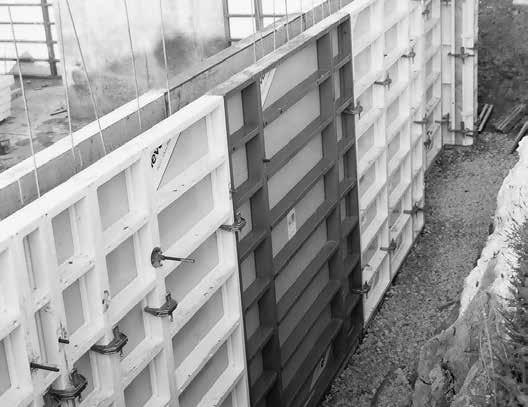
68 Formwork assembly and stripping Important! When assembling and stripping formwork, strictly observe the local accident prevention rules. Note Note that if the formwork is 2 m high or higher, both the inside and the outside formwork must be protected against falling over. Planning If you want to benefit fully from the efficient and economical use that the StarTec/AluStar formwork offers, we recommend you first plan and prepare its use. Start planning by determining the optimum formwork quantity to be held in stock (such quantity is usually based on the amount of formwork required for a one day s work). When determining the quantity, consider this: the formwork weight the time required for formwork assembly and stripping transport of panel gangs from one pour to the next considerably reduces forming time capacity of the lifting devices a logical cycle plan that takes corner configurations, reinforcements etc. into account Once all these aspects have been considered, the quantities of formwork items can be specified. Ground The ground on which the formwork is going to be placed should be clean, even and capabable of bearing the expected load because this will help reduce the time required for the assembly and stripping. Panel transport When unloading panels or moving panel stacks make sure you use appropriate transport devices that can bear the load. For details see p. ST/AS 72 through 75. The steps required for the assembly For ergonomic reasons, the outside formwork is ususally assembled and placed first. Start the assembly in a corner or at a determined point and perform the following steps: Step 1 Place and brace the outside formwork Step 2 Define and mark the pouring height, build in the reinforcements and bloxouts Step 3 Place the inside formwork and tie the outside and inside formwork Refer to the following pages for a detailed deschription of the formwork assembly including the working platform, and for a description of formwork stripping. Fig Double-sided formwork ST/AS 68
69 Formwork assembly and stripping Step 1 - Place and brace the outside formwork The following description is based on an even wall. Before starting, keep in mind: When preassembling large panel units on an even surface, attach the wall braces and the scaffolding bracket as well, i.e. before executing step 1. Walls of less than 6 m require a filler for easy stripping (Fig. 69.3) as otherwise the formwork may wedge when stripping and stick to the concrete. 1. Spray the facing with the release agent MevaTrenn FT8. If the scaffolding bracket was not preassembled before step 1, you can now assemble the working platform and attach it. Fig on page ST/ AS-70 shows a working platform being lifted with a crane for attachment at a braced outside formwork. 3. String further panels together and connect them with AS assembly locks (see p. ST/AS 8). The panels are usually connected with 2 assembly locks (Fig. 69.1). However, outside corner configurations require 3 assembly locks (see pages ST/AS-22 through 24). Fig Place the first panel and immediately attach it with two brace frames to the ground to prevent it from falling over (Fig. 69.1). Attach the foot plates firmly to the ground, with two soil nails when attached directly to the soil or with two heavy-duty dowels when attached to a concrete foundation. After plac ing panels, always reinforce them immediately with pushpull props or brace frames so they withstand tensile force and pressure and are protected against displacement and wind. The push-pull prop spacing depends on the application. Step 2 - Pouring height, reinforcements and boxouts Following step 1, the pouring height is defined and marked, the reinforcements and boxouts, if required, are installed. Step 3 - Place the inside formwork and tie the outside and inside formwork The inside formwork is placed after the outside formwork. Then the inside and outside formwork are tied firmly with tie rods and articulated flange nuts. Fig Fig Filler for easy stripping ST/AS 69
70 StarTec / AluStar Formwork assembly and stripping Working scaffold The plug-in scaffolding bracket (the figures show the BKB) is the basis for the working scaffold. The maximum bracket spacing for a load of 150 kg/m² (platform group 2) is 2.50 m as defined in DIN The planking must at least be 4.5 cm thick. The planking and scaffolding bracket can be firmly connected. Do not place any planks before having secured the formwork with push-pull props or before having tied the inside and the outside formwork. Do not forget to attach a side railing to the working scaffold if such a protection is required. Fig Fig Double-sided formwork with a working scaffold attached to the outside formwork ST/AS 70 st as ava.pdf St. 30/11/15 Printed in Germany Pouring concrete Once you have placed, attached and closed the formwork, you can start pouring concrete. When doing so, observe the admissible rate of placing, taking the temperature and cement type into account (see p. ST/ AS-11).
71 Formwork assembly and stripping Stripping Do not start stripping before the concrete has set to the point where it cannot deform anymore. It is best to start stripping at the stop ends or at a corner. Start stripping with the inside formwork. Stripping of both the outside and the inside formwork is done as follows: 1. Remove the platform. 2. Remove the articulated flange nuts and tie rods section by section. Make sure the unbraced formwork is immediately secured against falling over or strip it immediately. 3. Loosen the formwork panels or large panel units by removing the assembly locks at the panel joints and remove them manually or with a crane. Before removing them with a crane, make sure the formwork is detached from the concrete. 4. Clean the facing and remove any concrete. Before the next use, spray the facing with the release agent MevaTrenn FT8 (for alkus). Observe the operating instructions for the alkus facing. Attention The release agent must not be stored in galvanized containers Please note When stripping manually, detach and disassemble the working scaffold and the brace frames before stripping the panels. When transporting large panel units with a crane, the work ing scaffold and wall braces are not detached from the panel units. While in vertical position, all components are cleaned and sprayed before being transported together to the next site of use (see p. ST/AS 50 through 57). If there is no further use for the panel units, the working scaffold and wall braces are detached and disassembled in horizontal position, cleaned and stacked for transport. Fig Fig ST/AS 71
72 StarTec / AluStar Crane slings Stapos 40 These crane slings are made of polyester tape with double-sided textile coating. The load-bearing capacity is stamped on the coating. The sling is provided with a galvanized self-locking fastening device (Fig. 72.1). Handling 1. Place the panel stack on square timbers of 10 cm (Fig. 72.2). 2. Push the suspension device under the stack with your foot (Fig. 72.3). 3. Yank the sling up (Fig. 72.5). The elastic fastening pin will engage completely in the profile groove and secure the stack against accidental uplift (Fig. 72.4). Description Fig Fig Fig Crane slings Stapos ST/AS 72 Fig Fig st as ava.pdf St. 30/11/15 Printed in Germany Attention Four crane slings Stapos 40 are needed to move and transport panel stacks. They loop securely to the 4 corners.
73 Crane slings Stapos 40 While transporting the stack by crane the loadbearing capacity of the crane slings Stapos 40 is uniformly distributed to all slings. Just one person is required for attachment and removal of the slings. Attention The Stapos crane slings 40 may be used only in conjunction with double-rope crane devices in compliance with applicable safety regulations (Fig. 73.1). Only 2 crane slings may be used to calculate the admissible load. Fig Technical Data Description Crane slings Stapos Weight 3.1 kg Colour Green Admissible load 10 kn (1 ton) per sling Admissible unit weight 2 tons Usable for frame profile thickness 40 mm Maximum stack height 126 cm (10 panels) Maximum stack height for largesize 5 panels StarTec 270/240 panels Tabel 73.2 ST/AS 73
74 Crane slings 40 / Lifting hook 40 Crane slings The crane slings (Fig. 74.1) help to quickly load and unload trucks and move the StarTec panel stacks near the ground. The lifting hooks are inserted into the welded sleeves of the bottom panel frame. After tightening the crane slings check to make sure the hooks are safely locked. (Fig. 74.2). Attention A lifting hook must only be used if its eccentric is easy to turn or automatically falls into the locked position (Fig. 74.2). Never use a lifting hook if you need force to turn its eccentric. Turning the eccentric with force may not the lock the lifting hook but only make it appear to be in the locked position. This may cause the lifting hook to slip off its position when lifting the panel stack. Technical Data Max. load 20 kn (2 tons) per panel stack Max. stack height: 5 StarTec panels 270/240 or 10 StarTec panels 270/135 and smaller. Lifting hook The lifting hook (Fig and 57.3) can be used with any fourrope crane device on the construction site to transport Startec panel stacks. Always use 4 hooks together (Fig. 74.1). To calculate the admissible loadbearing capacity, assume only 2 hooks. When using a lifting hook, observe the Attention paragraph in the left column. Moving panel stacks When moving panel stacks, make sure panels are secured against slipping. MEVA secures them with safety bolts and, for truck transport, also with load/cargo straps (see p. ST/AS-76). Technical Data Weight 1.7 kg Max. load 10 kn (1 ton) Approx m Approx m Fig Locked position Fig Description Crane slings Lifting hook ST/AS 74
75 Transport angle By using transport angles (Fig. 75.1), 5 to 12 ST/AS panels can be stacked, stored and transported without the need for square timber under the stack. We recommend using 2 foldable angles and 2 of the rigid type for each stack. Transport angle 12 rigid The maximum load capacity is 10 kn (1 ton) per angle. For safety reasons consider 20 kn (2 tons) as maximum capacity for the whole stack. Fig Transport angle 12 Description Transport angle rigid ST/AS 75
76 Transport Make sure that all material is secured properly. Recommendation Use one load/cargo strap per 1 metre of cargo. That means for a fully loaded truck with a trailer length of m, 14 load or cargo straps would be required. ST/AS panels require 2 or 3 straps respectively. Due to their low weight, ST/ AS corners require only 2 straps. Fig When moving panel stacks make sure that panels are secured. MEVA secures StarTec panels 270/240 with the grey safety bolts 270/240 and all other AluStar and StarTec panels with the black ST/AS safety bolt (Fig. 76.2). These plugs should also be used by the job-site when returning material. Fig Safety regulations When using or transporting our products, the federal, state, and local codes and regulations must be observed. Description Safety bolt AS/ST black ST 270/240 grey ST/AS 76


77 Service Cleaning The formwork is cleaned professionally upon return. Cleaning is done using industrial equipment with assembly lines. Regeneration The regeneration is carried out as follows: The frames are checked and, if necessary, repaired, painted and provided with a new facing. As long as the formwork equipment is up-todate, a regeneration will always be a more economical solution than purchasing new formwork. Please note that the cleaning and regeneration service is not available in all countries in which MEVA does business. Rentals With much equipment on stock, we offer our customers the option of renting supplementary material during peak times. We also give prospective customers the chance to test MEVA formwork so they can see its benefits for themselves in actual use. RentalPlus Since MEVA started the flat rate for cleaning and repair of rented formwork systems in early 2000, more and more contractors experience the outstanding advantages. Ask our representatives about the details! Formwork drawings Of course, all offices in our technical department have CAD facilities. You get expert, clearly represented plans and work cycle drawings. Special solutions We can help with special parts, customdesigned for your project, as a supplement to our formwork systems. Static calculations Generally, this is only necessary for applications like single sided formwork where the anchor parts are embedded in the foundation or the base slab. If requested, we can perform static calculations for such applications at an additional charge. Formwork seminars To make sure that all our products are used properly and efficiently, we offer formwork seminars. They provide our customers a good opportunity to keep themselves up-to-date and to benefit from the know-how of our engineers. ST/AS 77
78 Notes ST/AS 78
Chapter 10 - Scaffolding Systems
 Chapter 10 - Scaffolding Systems Contents Chapter 10 - Scaffolding Systems... 10-1 Check and Oil the Pump Jacks... 10-4 Set Pump Jack Brackets... Error! Bookmark not defined. Set Pump Jack Poles... 10-5
TRIO 330 The framed panel formwork for heights of up to 3.30 m
 TRIO 330 The framed panel formwork for heights of up to 3.30 m product range 4.30 3.30 2 ties up to 3.30 m TRIO 330 The framed panel formwork for floor heights up to 3.30 m TRIO 330 is an independent formwork
Removable Aluminium posts
 Post Solent Sail Shades Ltd 120 Billington Gardens Hedge End Southampton SO30 2RT Tel/Fax: 01489 788243 www.solentsailshades.co.uk Email: [email protected] Removable Aluminium posts Single Pole
PUMP JACK SYSTEM AND ACCESSORIES
 Pump Jack Model # 2200 A low cost, easy to operate, safe, portable scaffolding built of rugged steel. It's perfect for shingling, siding, sheathing, insulating, painting, building, roofing, home repair
Ceiling Mounted Folding Attic Ladders Installation Instructions
 Ceiling Mounted Folding Attic Ladders Installation Instructions WARNING Before you start installing your new Louisville Ceiling Mounted Folding Attic Ladder, you must read and understand the following:
Wall braces with a swivel head are included to accommodate all roof pitches.
 ULTRA JACK MODEL # 2000 Wall braces with a swivel head are included to accommodate all roof pitches. Product Specifications Model # 2000 Description: Ultra Jack Unit Pack: Weight per Pack: 1 / Carton 32
Since it was established in 1989, with a small manufacturing base in Qwa Qwa and a hire yard in Botswana, Uni-Span
 formwork formwork Since it was established in 1989, with a small manufacturing base in Qwa Qwa and a hire yard in Botswana, Uni-Span has grown to become one of the major players in the scaffolding and
Window Installation Instructions
 Caution The correct installation methods of windows in full frame or insert applications is critical towards achieving the tested performance of the window and longterm enjoyment and energy savings for
TECHNICAL SPECIFICATION SERIES 8000 PRECAST CONCRETE
 TECHNICAL SPECIFICATION SERIES 8000 PRECAST CONCRETE TECHNICAL SPECIFICATION PART 8000 - PRECAST CONCRETE TABLE OF CONTENTS Item Number Page 8100 PRECAST CONCRETE CONSTRUCTION - GENERAL 8-3 8101 General
Mark Cramer Inspection Services, Inc.
 Mark Cramer Inspection Services, Inc. 492 Twentieth Avenue, Indian Rocks Beach, FL 34635-2970 (727) 595-4211 Fax (727) 596-7583 Certified Member #12085 American Society of Home Inspectors Construction
HORIZONTAL INSTALLATION
 THERMO/SOLAR Žiar s.r.o. MANUAL FOR INSTALLATION PV SUPPORTING FRAMES HORIZONTAL INSTALLATION Technical alternation reserved A1410 1 12/2014 CONTENT ORD.NO. PAGE Mounting information 3 Mounting, flat roof
Installation information. METTLER TOLEDO MultiRange DW150 / DW150T wall scale
 Installation information METTLER TOLEDO MultiRange DW150 / DW150T wall scale DW150 / DW150T wall scale Contents Contents Page 1. Installation... 2 1.1 Preparatory work... 2 1.2 Installing the wall plates
Best Barns USA Assembly Book
 Best Barns USA Assembly Book Revised November 27, 2013 the Easton - R 12'x 20' Manufactured by Reynolds Building Systems, Inc. 205 Arlington Drive Greenville, PA 16125 724-646-3775 This manual is copyrighted.
Installation guide for the SafeLine type anchorage device. Tested in compliance with EN 795: 1996. No.: SE-...
 Installation guide for the SafeLine type anchorage device Tested in compliance with EN 795: 1996 No.: SE-... Version: 09.10.2008 SE 67 Subject to technical alterations! Contents 1. General information
CONCRETE FLOOR SLAB & CASTING BED CONSTRUCTION
 CONCRETE FLOOR SLAB & CASTING BED CONSTRUCTION General 7 www.meadowburke.com 877-518-7665 MB1109 CONCRETE FLOOR SLAB AND CASTING BED CONSTRUCTION Quality Construction Begins at Ground Level Everything
Installation information. METTLER TOLEDO MultiRange Floor scales / Pit scales
 Installation information METTLER TOLEDO MultiRange Floor scales / Pit scales KC300/KCS300 KC600/KCS600 KD600/KD1500 KE1500/KE3000 KES1500/KES3000 KG3000/KG6000 KN1500 Floor scales / Pit scales Contents
Formwork Direct International Ltd Phone No +44 (0151) 532 0179 Fax no +44 (0151) 523 8330 E-Mail: [email protected].
 532 0179 Fax no +44 (0151) 523 8330 E-Mail: sales@formworkdirect.co.") Tie Rod & Formwork s well as containing our comprehensive range of Formwork Tie Sytems; this section also covers our market leading Rapidobat Column Former. Exclusive also to Formwork Direct are innovations
Tie Rod & Formwork s well as containing our comprehensive range of Formwork Tie Sytems; this section also covers our market leading Rapidobat Column Former. Exclusive also to Formwork Direct are innovations
39HQ Airovision Air Handling Units
 39HQ Airovision Air Handling Units Mounting instructions CONTENTS 1 - TRANSPORT AND LIFTING INSTRUCTIONS... 3 1.1 - General... 3 1.2 - Transport and storage... 3 1.3 - Roof edge protection during transport
BRIO Modular scaffolding
 BRIO Modular scaffolding // Versatile and multifunctional // Table of content Features Benefits Solutions Basic components 2 4 6 11 // Features BRIO Modular Scaffolding covers the different configurations
MAXIMO The panel formwork with the MX Tie which is installed from one side only
 MAXIMO The panel formwork with the MX Tie which is installed from one side only The PERI MX Tie Edition 02/2010 PERI GmbH Formwork Scaffolding Engineering P.O. Box 1264 89259 Weissenhorn Germany Tel +49
High Strain Dynamic Load Testing of Drilled Shafts
 Supplemental Technical Specification for High Strain Dynamic Load Testing of Drilled Shafts SCDOT Designation: SC-M-712 (9/15) September 3, 2015 1.0 GENERAL This work shall consist of performing high-strain
7. PRINCIPAL STEPS 8. POTENTIAL HAZARDS 9. RECOMMENDED CONTROLS
 ACTIVITY HAZARD ANALYSIS (AHA) 1. Contract Number: 2. Contractor Name: 3. Date prepared: 4. Title/Activity Performed: FIXED SCAFFOLDING 5. Location: 6. Estimated Date of Completion: 7. PRINCIPAL STEPS
Sliding and Folding Door Fittings Sliding Door Accessories
 Sliding door lock Toplock For 1- and 2-leaf sliding doors Suitable for toughened safty glass and laminated sheet glass Suitable for DIN left and DIN right Max. weight per door leaf 120 kg For glass thickness:
The minimum reinforcement for the stem wall is the placement of:
 PolySteel creates an ideal insulated stem wall for concrete slabs that can make this part of your project easier and faster, in addition to making your finished project more energy-efficient. Figures 3.20
General Safety. Always do a risk assessment.
 recipitous.co.uk Access Equipment Call 020 8684 6999 Scaffold Towers Ladders & Steps Podiums Rigging Tube & Fittings New & Used Sales Hire Repair Manufacture The Skymaster Ladder is a 3 section combination
DE Frame with C Series Sidelight
 TOOLS REQUIRED Tape measure 6' magnetic level 3' magnetic level Screw gun with clutch adjusted #2 phillips tip #3 phillips tip Screwdriver (used to adjust frame on will using oval slots) Pry Bar Powder
Front axle components, overview
 just a test. Front axle components, overview 40-1 General Information Load bearing components and parts of the suspension must not be welded or straightened. Vehicles without drive axle must not be moved,
How To Build A Gambrel Roof And A Gable End Roof
 Dutch Gable or Gambrel Roof and The Scotch Valley The folowing pages are an extract from Carp 12 text TAFE NSW Construction and Transport Division 71 HIP and VALLEY ROOFING GAMBREL / DUTCH GABLE The effect
2100 AD 015 0009 Mirror Elevator Ball Nut Replacement Procedure
 2100 AD 015 0009 Mirror Elevator Ball Nut Replacement Procedure Derek Guenther 1/28/2015 Rev. Purpose The purpose of this document is to describe the procedure necessary to replace one of the ball nuts
ASSEMBLY INSTRUCTIONS Residential Roof solutions
 ASSEMBLY INSTRUCTIONS Residential Roof solutions CROSSRAIL System USA Table of contents TABLE OF CONTENTS THE COMPANY SAFETY REGULATIONS MATERIALS REQUIRED TOOLS REQUIRED ASSEMBLY TERMS AND CONDITIONS
C O N V E Y O R C O M P O N E N T S C H A I N S B E L T S B E A R I N G S
 C O N V E Y O R C O M P O N E N T S C H A I N S B E L T S B E A R I N G S January 2009 Issue 6 Valu Guide Brackets The Ultimate in Adjustability and Cost Savings Valu Guide brackets are part of a family
Owner's Manual & Assembly Instructions
 Owner's Manual & Assembly Instructions PM01 BASE KIT Model No. FDN1014 717090311 CAUTION: SOME PARTS HAVE SHARP EDGES. CARE MUST BE TAKEN WHEN HANDLING THE VARIOUS PIECES TO AVOID A MISHAP. FOR SAFETY
Materials. Estimating Steel. Players. Materials. Shop Drawings. Detailing Process. Standard shapes. Fabricated members, Built-up sections
 Materials Standard shapes W sections, C channels, Structural T, Angles, Pipes, Tubes, Rods and Plates Fabricated members, Built-up sections Adding plates to beam flanges, Stiffeners to beam webs Built
PaLLe t trucks Lifting carts t r g in t if L 2435 6815 6836 6856 6842
 l i f t i n g c a r t s Lifting carts The prograe for lifting, transporting and storage From the classical forklift trolley to the machine lifter, from furniture dollies to a chassis with 24 tons load
Structural Holding System
 Structural Holding System Users Manual November 2013 by Vehicle Service Group. All rights reserved. CO8812.1 502071 Rev. - 11/21/2013 CHIEF'S LIMITED ONE-YEAR WARRANTY & LIABILITY Chief Automotive Technologies
Preface nivtec.com 3
 nivtec.com Preface nivtec.com 3 nivtec 4 nivtec.com Planning with an Eye for Details nivtec.com 5 prolight+sound 2012 6 nivtec.com Meeting Point Fair Booth nivtec.com 7 Our Preparations 8 nivtec.com Enable
Layher. Protective Systems. More Possibilities. The Scaffolding System. Layher Keder Roof and Keder Hall Instructions for Assembly and Use
 Layher Keder Roof and Keder Hall Instructions for Assembly and Use Quality management certified according to DIN EN ISO 9001:2000 by German TÜV-CERT Protective Systems Layher More Possibilities. The Scaffolding
Linear modules Lifting units Rotary modules Grip modules Inductive proximity switches Plug connectors
 20000 Linear modules Lifting units Rotary modules Grip modules Inductive proximity switches Plug connectors 23000 22000 21000 20000 09000 08000 07000 06000 05000 04000 03000 02000 01000 823 Notes 824 Technical
Pipe Clamps and Accessories
 Products 4.0 Products 4.1 Connection options to pipe clamps with Triple-Thread Connector NT 3G (M16, M10, M8) 4.2 Connection options to pipe clamps with Triple-Thread Connector NT 3G (3/8", M12, M10) 4.3
Installation Instructions
 Installation Instructions READ BEFORE INSTALLING UNIT For Low Profile Window Air Conditioner INSTALLATION WARNINGS AND CAUTION Carefully read the installation manual before beginning. Follow each step
STRUCTURAL CONCEPT FOR LIGHT GAUGE STEEL FRAME SYSTEM
 Chapter 9 STRUCTURAL CONCEPT FOR LIGHT GAUGE STEEL FRAME SYSTEM 9.1 BACKGROUND Steel is widely used in the construction of multi-storey buildings. However, steel construction is seldom used and is traditionally
LIBERA USER S MANUAL
 USER S MANUAL 2002 Litec s.r.l. Italy All rights reserved. No parts of this manual can be reproduced, without permission of Litec s.r.l. Cod. Version 2 Pag. 2 di 23 INDICE 1. Introduction.... 3 2. The
PITCHED ROOF STRUCTURES
 PITCHED ROOF STRUCTURES for framed and frameless photovoltaic modules Needed tools and materials: cordless screwdriver 10mm and 13mm spanners 5mm Allen key bolts, screws and tools for fixing the system
Schlüter -KERDI-BOARD Substrate, structural panel, bonded waterproofing
 Substrate, structural panel, bonded waterproofing The universal substrate for tiles Perfect covering No matter whether you work with mosaics or large format tiles, an absolutely level substrate with straight
Residential Deck Safety, Construction, and Repair
 Juneau Permit Center, 4 th Floor Marine View Center, (907)586-0770 This handout is designed to help you build your deck to comply with the 2006 International Residential Building code as modified by the
HS-Steel-Classic. Curing chambers for the concrete block industry in a proven steel version
 ANLAGENTECHNIK HS-Steel-Classic Curing chambers for the concrete block industry in a proven steel version + special galvanising + simple assembly due to snap-in connections and building kit system We build
Fixturing systems Fixturing systems for measurement technology
 Fixturing systems Fixturing systems for measurement technology Innovations and new additions to range Sets Spannfix Eco complete set The set contains different supports, extension elements and stop units.
FORM DESIGN. easy to work with, and generally available.
 Forms play a major role in concrete construction. They give the plastic concrete its shape and hold it until it hardens. Forms protect the concrete, assist in curing it, and support any reinforcing rods
POST AND FRAME STRUCTURES (Pole Barns)
") POST AND FRAME STRUCTURES (Pole Barns) Post and frame structures. The following requirements serve as minimum standards for post and frame structures within all of the following structural limitations:
POST AND FRAME STRUCTURES (Pole Barns) Post and frame structures. The following requirements serve as minimum standards for post and frame structures within all of the following structural limitations:
Guidelines for Earthquake Bracing of Residential Water Heaters
 Guidelines for Earthquake Bracing of Residential Water Heaters Department of General Services Division of the State Architect 1102 Q Street, Suite 5100 Sacramento, CA 95814 Phone: (916) 324-7099 Fax: (916)
WHI 90-Minute Rated Veneered Door Frame Installation Instructions
 No. 940-03-10 INSTALLATION INSTRUCTIONS 90 MINUTE RATED VENEERED DOOR FRAME DOOR REQUIREMENTS: Consult the door manufacturer to make sure that the doors are qualified for the hardware to be installed,
WOLFFKRAN. 1 Schedule drawing. 1.1 Schedule drawing, WOLFF 6023.6clear. max. hook height above ground. Data WOLFF 6023.6clear
 1 Schedule drawing 1.1 Schedule drawing, WOLFF 6023.6clear [X] max. hook height above ground Data WOLFF 6023.6clear Item Crane type Design Type of setup Basis of calculation Payload torque Hoist winch
Speed-Mat Rectangle Cutter
 Speed-Mat Rectangle Cutter 1 Honeycomb baseboard. 2 Left hold down. 14 3 Bottom hold down. 4 4 Left / right rule. 8 5 8 5 Left / right rule pointer. 1 6 Top / bottom rule. 7 Top / bottom rule pointer.
UNIVERSAL RAILING, STEEL
 RAILINGS Page Universal Railing, steel 108-109 Large Module Railing, steel 110-111 Allround Railing, aluminium 112-113 Module Railing, aluminium 114-115 Standard Type Railing, aluminium 116-117 107 UNIVERSAL
STEADYfast Stabilizer Installation Notes Fifth Wheel and Travel Trailers 11/23/13
 STEADYfast Stabilizer Installation Notes Fifth Wheel and Travel Trailers 11/23/13 (See Supplemental Instructions for trailers with heavy duty round footplates and/or Power Leveling Systems) PHONE SUPPORT
Technical handbook Panel Anchoring System
 1 Basic principles of sandwich panels 3 Design conditions 4 Basic placement of anchors and pins 9 Large elements (muliple rows) 10 Small elements (two rows) 10 Turned elements 10 Slender elements 10 Cantilevering
DIY CABINET REFACING INSTALLATION GUIDE
 DIY CABINET REFACING INSTALLATION GUIDE CABINET REFACING INSTALLATION Are you ready to reface your outdated cabinets? This guide will show you how to install your new Facelifters Cabinet Refacing Products
It's large enough to handle most welding job shop projects, yet small enough to make it a worth while home-workshop tool
 It's large enough to handle most welding job shop projects, yet small enough to make it a worth while home-workshop tool H Craft Print Project No. 272 ERE'S a metal bender that will enable you to bend
PANELIZED HOME INSTALLATION GUIDELINE
 PANELIZED HOME INSTALLATION GUIDELINE A typical home package will be constructed of Snap-N-Lock Insulated Panels clad with steel skins. 4" panels will be used for the walls, and 6" panels for the roof.
Stair Parts Installation. Tricks
 Stair Parts Installation Tips & Tricks Introduction Your DIY staircase guide Welcome to the Stairpart home installation guide. Your stairway is both a functional and focal point in your home, so keeping
Superform Products Ltd.
 TYPICAL CORNER REINFORCING NOTE : SEE ENGINEERED REBAR SCHEDULES SUPPLIED BY THE MANUFACTURER STEEL REINFORCEMENT WALL CORNER 90 Copyright 2012 Sept. 2012 5.1.1 Rebar Spacing 6" 12" Max. Load LB./FT. 2000
WINDOW INSTALLATION GUIDE FOR NEW CONSTRUCTION - WOOD FRAMING
 WINDOW INSTALLATION GUIDE FOR NEW CONSTRUCTION - WOOD FRAMING IMPORTANT NOTICES AND INFORMATION Read these instructions in their entirety prior to installing windows. Any local building code requirements
Embedded Parts Introduction - Anchors
 In the plant construction or process plants such as chemical, petrochemical, gas or power plants various disciplines are brought into contact and built on each other. Civil, mechanical, electro technical
Rooflight INSTALLATION INSTRUCTIONS
 INSTALLATION INSTRUCTIONS Rooflight These instructions should be used for: Installing Permanent Trickle Ventilation: Constructing & Waterproofing a Timber Upstand Curb: Installing & Waterproofing Proprietary
SHUTTER INSTALLATION INSTRUCTIONS. AUGUST 2006 Version 2
 SHUTTER INSTALLATION INSTRUCTIONS AUGUST 2006 Version 2 All rights reserved; no part of this publication may be reproduced, stored in a retrieval system, or transmitted in any form or by any means, electronic,
Chapter 3 Installing Over-the-Post Railing on an L-Shaped Stair
 49 Chapter 3 Installing Over-the-Post Railing on an L-Shaped Stair In this chapter: The Over-the-Post Balustrade System Determining the Rail Centerline Using Rail Bolts Making a Pitch Block Laying Out
Pole Lathe and Shave Horse Design
 Pole Lathe and Shave Horse Design These pictures and accompanying words are Copyright Michael Hughes February 2002. They are not to be re-produced, in part or whole, without permission from the author.
The WANZ Guide to Window Installation
 The WANZ Guide to Window Installation as described in E2/AS1 Amendment 5 Ver. 1.1 Page 2 of 74 Contents Overview Page 5 Objective Page 5 Scope Page 5 Opening Preparation Page 7 Step P1 Preliminary Check
Clad Direct Glaze Window Installation Instructions
 Clad Direct Glaze Window Installation Instructions Sill flashing and sealing: 2. An overview of the proper flashing sequence is shown in figure 1. Please read entire installation instructions carefully
Installation Instructions For Slider Casement Air Conditioners
 Installation Instructions For Slider Casement Air Conditioners NOTE: These instructions describe installation in a typical wood framed window with a wood SLIDE-BY sash, or installation in a metal CASEMENT
After reading this lesson you will be able to: 12.3 IMPORTANCE OF ROOF 12.4 TYPES OF ROOF IN A HOUSE
 86 :: Certificate in Construction Supervision (CIVIL) 12 ROOF 12.1 INTRODUCTION The structure provided to cover the house surface (floor) is known as roof. For different situation and requirement, it is
Machine devices, jig devices
 Machine devices, jig devices 853 K0697 Rolled thread studs DIN 6379 Material: Tempered steel. KIPP Rolled thread studs DIN 6379 Order No. D L B1 B2 Approx. weight g Surface finish: Thread rolled. Class
CONFER ABOVE GROUND CURVE STEP / ABOVE GROUND CURVE STEP SYSTEM ASSEMBLY AND INSTALLATION MANUAL
 SAVE THESE INSTRUCTIONS DEALER/INSTALLER: GIVE TO HOMEOWNER CONFER ABOVE GROUND CURVE STEP / ABOVE GROUND CURVE STEP SYSTEM ASSEMBLY AND INSTALLATION MANUAL Model CCX-AG Note: 40 lbs. of sand required!
UNIVERSAL ASSEMBLY INSTRUCTIONS FOR VERSATUBE BUILDINGS CONTRACTOR SERIES 2 X 4 FRAMES
 UNIVERSAL ASSEMBLY INSTRUCTIONS FOR VERSATUBE BUILDINGS CONTRACTOR SERIES 2 X 4 FRAMES Our unique assembly process quickly transforms the individual pieces into a finished structure that will give you
MEASURING WHEEL ALIGNMENT
 MEASURING WHEEL ALIGNMENT 2003-04 WHEEL ALIGNMENT Specifications & Procedures - Hummer - H2 Steering and vibration complaints are not always the result of improper alignment. One possible cause is wheel
Panel Track Installation Guide
 Panel Track Installation Guide We make it easy! BTG 493361 EN_0510 Before starting Your new Blinds To Go panel track is custom made to your specifications from the finest materials available. To ensure
PLM series Permanent load lifting magnets
 Lifting gear Load lifting magnets/chain hoists PLM series Permanent load lifting magnets Load-bearing capacity of up to 1 t depending on model despite light weight High standard of safety with simple lever
SELF-STEERING AXLE TABLE OF CONTENTS
 SELF-STEERING AXLE TABLE OF CONTENTS Section 1 - Introduction Section 2 - Pre-Installation Check List Section 3 - Ride Height Adjustments Section 4 - Suspension Mount Section 5 - Axle Mount Section 6 -
9.8.1.1. General (1) This Section applies to the design and construction of interior and exterior stairs, steps, ramps, railings and guards.
 This Section applies to the design and construction of interior and exterior stairs, steps, ramps, railings and guards.") Section 9.8. Stairs, Ramps, Handrails and Guards 9.8.1. Application 9.8.1.1. General (1) This Section applies to the design and construction of interior and exterior stairs, steps, ramps, railings and
Section 9.8. Stairs, Ramps, Handrails and Guards 9.8.1. Application 9.8.1.1. General (1) This Section applies to the design and construction of interior and exterior stairs, steps, ramps, railings and
K. D. FRAME ASSEMBLY FOR CLOSED STEEL STUD WALLS...Ins 10. FRAME INSTALLATION DETAILS FOR CLOSED STEEL STUD WALLS...Ins 11
 K. D. FRAME ASSEMBLY FOR MASONRY WALLS...........................Ins 2 FRAME INSTALLATION DETAILS FOR MASONRY WALLS......................Ins 3 INSTALLING EXISTING MASONRY WALL ANCHORS IN FRAME..................Ins
OWNER S MANUAL Table Tennis Table Patent Pending
 OWNER S MANUAL Table Tennis Table Patent Pending Be sure to write your model number and serial number here for future reference. You can find these numbers printed on the bottom of the table. MODEL # T8179
Chapter. Restoration of Damaged Structures
 5 Chapter Restoration of Damaged Structures Bringing back a damaged structure to its pre-earthquake state and original strength is called restoration. This is the first step of building rehabilitation.
12.1 Schlüter -KERDI-BOARD
 I n n o v a t i v e p r o f i l e s 12.1 Schlüter -KERDI-BOARD S u b s t r a t e U N I V E R S A L S T R U C T U R A L P A N E L, B O N D E D W A T E R P R O O F I N G Application and Function Schlüter
2.9 WINDOW & DOOR BUCKS
 2.9 WINDOW & DOOR BUCKS Bucks provide attachment surfaces for windows and doors while holding back concrete from these openings during concrete placement. Mark the center and edges of openings as you place
STANDARD REQUIREMENTS FOR BONDING OR MECHANICAL ATTACHMENT OF INSULATION PANELS AND MECHANICAL ATTACHMENT OF ANCHOR AND/OR BASE SHEETS TO SUBSTRATES
 ROOFING APPLICATION STANDARD (RAS) No. 117 STANDARD REQUIREMENTS FOR BONDING OR MECHANICAL ATTACHMENT OF INSULATION PANELS AND MECHANICAL ATTACHMENT OF ANCHOR AND/OR BASE SHEETS TO SUBSTRATES Scope 1.1.
FL ADJUSTABLE RIDER BACKREST MOUNTING HARDWARE KIT
 -J070 REV. 0-0-0 FL ADJUSTABLE RIDER BACKREST MOUNTING HARDWARE KIT GENERAL Kit Number 9-09A Models For model fitment information, see the P&A Retail Catalog or the Parts and Accessories section of www.harley-davidson.com
COMBINATION SLAB & TRIM SAW INSTRUCTIONS 12, 14, & 16 MODELS
 COMBINATION SLAB & TRIM SAW INSTRUCTIONS 12, 14, & 16 MODELS DESCRIPTION Covington s Combination Trim & Slab Saws are similar in design with different blade and pulley sizes. Sawing operations remain the
INSTRUCTIONS: LocknCharge Laptop Carts
 INSTRUCTIONS: LocknCharge Laptop Carts www.lockncharge.com Extra Tools required: Hammer, Philips head screwdriver, medium adjustable spanner. (Allen key supplied) (Panel colours for illustration purposes
Cable Support System Guide for Andersen Bow, Bay, and Box Projecting Window Units
 for Andersen Bow, Bay, and Box Projecting Window Units Congratulations! You have just purchased one of the many fine Andersen products. Proper assembly, installation and maintenance are essential if the
BUILDING MATERIALS, Wood, Laminated (Page 1 of 3) Viz.: Rafters; Arches; Beams; Joists; Timbers or Planks, structural or roof.
 Viz.: Rafters; Arches; Beams; Joists; Timbers or Planks, structural or roof.") BUILDING MATERIALS, Wood, Laminated (Page 1 of 3) Viz.: Rafters; Arches; Beams; Joists; Timbers or Planks, structural or roof. 1155 & 4155 LCL: Applies to all freight in less than container load quantities.
BUILDING MATERIALS, Wood, Laminated (Page 1 of 3) Viz.: Rafters; Arches; Beams; Joists; Timbers or Planks, structural or roof. 1155 & 4155 LCL: Applies to all freight in less than container load quantities.
DRAINAGE MATS For Vertical: Flow 15-P For Horizontal: Flow 18-H
 DRAINAGE MATS For Vertical: Flow 15-P For Horizontal: Flow 18-H Soil Drainage Mat with Built-In Protection Layer POLYGUARD DRAINAGE MATS are three-part prefabricated geocomposite drain consisting of a
Hanson Building Products. precast basement solutions
 Hanson Building Products precast basement solutions Hanson Building Products Basement Systems Add an extra dimension and combine the inherent flexible, structural and waterproof properties of concrete
5 axle Lowbed Semitrailer with Automatic Steering Model ST 70-93 L3. (Lowbed length approx. 14,000 mm) Technical Specification no.
 Technical Specification no.") 5 axle Lowbed Semitrailer with Automatic Steering Model ST 70-93 L3 (Lowbed length approx. 14,000 mm) Technical Specification no. ST 70-93 L3 06/02 5 axle Lowbed Semitrailer with automatic steering Model
5 axle Lowbed Semitrailer with Automatic Steering Model ST 70-93 L3 (Lowbed length approx. 14,000 mm) Technical Specification no. ST 70-93 L3 06/02 5 axle Lowbed Semitrailer with automatic steering Model
Calvert USA, Inc. Attic Stairs
 Calvert USA, Inc. Attic Stairs Instructions for installation of vertical opening access stairs Model numbers: 7035 through 7047 Calvert USA, Inc., P.O. Box 841, Solomons, MD 20688, Tel. (410) 286-1430,
MONDOATHENS BASKETBALL SET (Reference PK110)
") MONDOATHENS BASKETBALL SET (Reference PK110) DESCRIPTION The MONDOATHENS backstop unit is mainly designed for multi-sports pavilions and installations where the highest-level basketball competitions are
MONDOATHENS BASKETBALL SET (Reference PK110) DESCRIPTION The MONDOATHENS backstop unit is mainly designed for multi-sports pavilions and installations where the highest-level basketball competitions are
Lunette 2 Series. Curved Fixed Frame Projection Screen. User s Guide
 Lunette 2 Series Curved Fixed Frame Projection Screen User s Guide Important Safety and Warning Precautions Please follow these instructions carefully to ensure proper maintenance and safety with your
Built to Last. Built for Beauty. Good. Solid. Logix. TM
 Built to Last. Built for Beauty. Good. Solid. Logix. TM Quality, Value and Service Introducing LOGIX Insulated Concrete Forms. Based on the simple concept of interlocking blocks, LOGIX ICF gives you a
Designed and Engineered to Perform
 History EARTH CONTACT PRODUCTS, L.L.C., is a family owned company, based in Olathe, Kansas. This company was built upon Don May s U.S. Patented fourth-generation Steel Piering System that has led to the
Auxiliary Rams USERS MANUAL
 Auxiliary Rams 2007 Chief Automotive Technologies, Inc. Chief s Limited One-Year Warranty & Liability CHIEF'S LIMITED ONE-YEAR WARRANTY & LIABILITY Chief Automotive Technologies, Inc. warrants for one
INSTALLATION. General. Important Note. Design. Transport
 General The roof trusses you are about to install have been manufactured to precise engineering standards. To ensure that the trusses perform as designed, it is essential that they be handled, erected