Fatigue of Welded Pressure Vessels
|
|
|
- Derek Casey
- 7 years ago
- Views:
Transcription


")
1 Fatigue of Welded Pressure Vessels CCOPPS Webinar Wednesday 21 st May :00 16:00 BST Steve Maddox Jim Wood The Welding Institute (TWI) University of Strathclyde
2 Agenda Introduction and Relevant CCOPPS Activity Jim Wood Fatigue of Welded Pressure Vessels Steve Maddox Q&A Session Steve Maddox & Jim Wood Closing Remarks Jim Wood
3
4 Industry Needs Survey Findings relevant to this webinar: FEA use is increasing as is complexity of models Interfacing with codes of practice seen as issue Happy with facilities in commercial codes in general (exception is weld modelling and assessment + automation of the analysis process) Non-European Codes are used often by most respondents. P li i t il bl f d l d f Preliminary report available for download from


5
6


7
8
9


10


11
12
13
14
15
16 Agenda Introduction and Relevant CCOPPS Activity Jim Wood Fatigue of Welded Pressure Vessels Steve Maddox Q&A Session Steve Maddox & Jim Wood Closing Remarks Jim Wood
17 Fatigue design of welded pressure vessels BS PD 5500 Annex C, Detailed fatigue assessment EN and - use of design curves ASME VIII, Division 2 - classification of weld details (new structural - stress concentrations stress approach) - fatigue life improvement Fatigue failure in Simplified assessment methods pressure vessels Fatigue assessment of welding Fatigue design data imperfections Stresses used in Future needs fatigue design
18 Effect of welding on fatigue resistance Stress range, MPa R=0 Grade 50 structural steel Cycles


19 Fatigue cracking in a welded joint Fatigue cracking from weld root Fatigue failure in plate at toe (from pre-existing sharp flaw at X) X
20 Key features of welds and welded joints Sharp section changes - High SCF Local discontinuities - Crack initiation sites High tensile residual stresses - Maximum mean stress effect, compressive Consequences: stresses damaging Relatively low fatigue strength, dominated by fatigue crack growth and controlled by full applied stress range. Fatigue life not increased by use of higher strength material
21 Fatigue failure in pressure vessels Fatigue loading Pressure fluctuations Temperature changes Temperature differentials External mechanical loading Vibration Sources of stress concentration and hence fatigue cracking Joints (welds, bolts) Geometric discontinuities (openings, nozzles, ends, supports) Temporary attachments
22 Fatigue failure from weld details Fatigue cracking from inside of butt weld between a cylindrical shell and a flat end Fatigue cracking from nozzle weld toe
23 Fatigue design process Compare number of repetitions (n i ) of stress range Sr i which vessel or part of vessel must withstand in its service life with the number (N i ) withstood by representative specimens at same stress in fatigue tests, such that: n n n n etc = Σ i 1. N N N N N values obtained from relevant design S-N curves i
24 Basis of fatigue design data and assessment method for welded joints BS PD 5500 and EN adapted from nominal stress-based fatigue rules for welded structures (bridges, offshore structures, etc) Thus, grid of S-N curves each applicable to one or more particular weld detail, chosen on the basis of a classification system In general, curves related to structural stress range For potential fatigue failure from weld toe, structural stress range at toe (hot-spot structural stress range) may be used New ASME VIII uses only hot-spot structural stress calculated in a specific way and converted to a fracture mechanics based parameter called the Equivalent structural stress range parameter
25 Stress range S r N/mm 2 World Centre for Materials Joining Technology Fatigue design curves for weld details in BS PD 5500 and other UK Standards S r 3 N = constant for N < 10 7 cycles Applicable to any of metals covered 5 S r N = constant by PD 5500, on for N > 10 7 cycles basis of relative E values For thickness e > e ref, where e ref =22mm, allowable stress e 10 7 ref = Sr. y e E = 2.09 x 10 5 N/mm 2 Class D E F F2 G W Endurance N, cycles
26 Weld detail classification in BS PD 5500 Classification depends on: welded joint geometry direction of loading crack initiation site methods of manufacture and inspection
27 Stresses used in BS PD 5500 for fatigue design Structural (primary + secondary) stress range Principal stress (not stress intensity) used directly Nominal stress for simple details (e.g. attachments, seam welds) Nominal stress x SCF for structural details, or Hot-spot structural stress at any weld toe (Higher design curve than those used with nominal stress) Net section of load-carrying fillet welds
28 Fatigue design S-N curves for weld details in EN Stress range S r N/mm 2 Class Class = fatigue strength in N/mm 2 at 2 x 10 6 cycles S r 5 N = constant for N > 5x10 6 cycles Currently applicable only to steel For thickness e > 25mm, allowable stress 3 S r N = constant for N < 5 x 10 6 cycles 2x10 6 5x10 6 Endurance N, cycles = S r 25mm. e 0.25
29 Stresses used in EN for fatigue design Structural (primary + secondary) stress range Option to use principal or equivalent stress range Nominal stress for simple details (e.g. attachments, seam welds) Structural stress at any weld toe (Hot-spot stress) Net section of load-carrying fillet welds
30 Vessel shell World Centre for Materials Joining Technology Weld detail classification in EN Ring stiffener Class 71 EN offers choice of using equivalent stress or principal stress. Since equivalent stress has no direction, a consequence is that the lowest detail Class must Hoop stress be assumed. Longitudinal Thus, the joint shown stress would be designed as Class 71. Class 80
31 ΔS ess World Centre for Materials Joining Technology Fatigue design curves from ASME VIII MPa/mm ASME 'Master' fatigue design curves Mean - 3SD (normal design curve) Mean - 2 SD Endurance, cycles Applicable to any of metals covered by ASME on basis of relative E values Stress parameter depends on plate thickness, membrane/bending stress ratio and applied stress ratio (Not units of stress) No other thickness correction required
32 Basis of fatigue design curves Regression analysis of S-N data obtained from tests on actual welded joints 2.5% probability of failure (mean 2 standard deviations of log N [SD]):- BS PD 5500 design curves; included in ASME. 0.1% probability curves (mean - 3SD):- BS PD 5500 simplified design methods; all EN design curves for weld details; generally required for ASME
33 Application of design curves for weld details No effect of applied mean stress in PD 5500 and EN 13445; mean stress correction in ASME No effect of material tensile strength No effect of welding process May need to be reduced to allow for corrosive environment; no specific guidance in BS PD 5500 or EN but penalty factors specified in ASME
34 Stresses used in ASME VIII Div. 2 for fatigue design of welded joints Structural (primary + secondary) stress range based on through-thickness stress distribution obtained by numerical analysis Structural equivalent stress range parameter (a function of material s fatigue crack propagation properties (m=3.6), applied structural stress range (Δσ), material thickness (t), membrane to bending stress ratio and applied stress ratio): ΔS ess = t 2 2 m m ess Δσ.I m 1.f M
35 Generalized stress parameter (Maddox, 1974) da / dn = C( Δ K ), ΔK = YΔσ πa, Y = a f t a i t (Y d ( a t πa t ) ) m m = I = m C Δσ m t ( m 2 1) N f ( a / t m m ( 1) 1 2 t i.e Δ σ.n = 1 = cons tant I C or where or Δσ * ( * ) Δσ m.n = a cons tant, ' Generalized stress Δσ = (cf MASME ΔS 2 m m t 2 m.i 1 parameter' Δσ ess ) * & crack t = Δσ front m 2 I 1 m 1 shape a / 2c )
36 ASME Equivalent structural stress range parameter ΔS ess Based on: Structural stress (presumably assumed to allow for SCF factor M k normally applied to stress intensity factor) Fatigue life mainly growth of a pre-existing crack Implicit assumptions made about initial flaw size and shape Specific fatigue crack growth rate relationship


37 Hot-spot structural stress approach Fatigue crack Hot-spot Hot-spot stress = structural stress at weld toe. It includes all stress concentrating effects except the local notch effect of the weld toe.
38 Hot-spot structural stress from through-thickness stress distribution Actual stress Structural stress σ hot-spot t τ(y) σ x (y) τ m σ m σ b
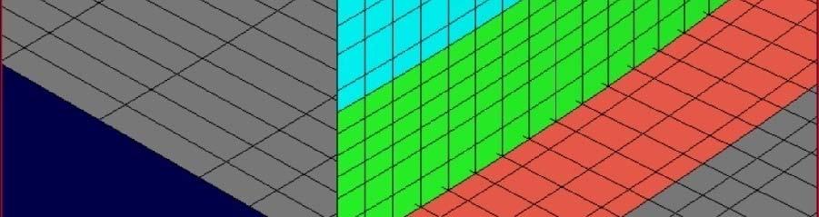
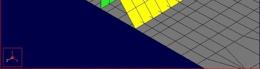
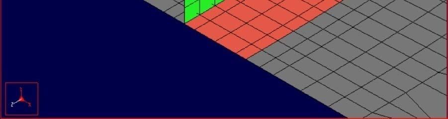
39 Methods for calculating the hot-spot structural stress Using surface stresses (e.g. measured): Surface stress extrapolation (SSE) Using through-thickness stress distribution (e.g. from numerical analysis): - Through-thickness integration (TTI) - Nodal forces (NF) method
40 Hot-spot stress developments in British Standards Current TWI joint-industry project aims to produce guidance on hot-spot structural ral stress approach for inclusion in British Standard fatigue design rules (initially BS 7608) Comparison of the three methods of calculating hot-spot stress (SSE, TTI and NF) from FEA Solid and shell elements, examination of sensitivity to mesh size Case studies on range of structural components All methods mesh sensitive but mesh sensitivity least for simple welded joints in plates under unidirectional loading Findings so far indicate that nodal force method most mesh sensitive of the three when applied to structural component Mesh insensitivity of the ASME method may be for a restricted set of possible mesh types and weld meshing options.
41 Fatigue data expressed in terms of hotspot stress range (SSE method) Hot-spot stress range at weld toe 200 N/mm 2 Class E Pressure vessels - nozzles Plate welded components 95% confidence intervals enclosing data x10 7 Endurance, cycles
42 Hot-spot stress range at weld toe Comparison with mean 2SD S-N curves derived from ASME VIII N/mm 2 BS PD 5500 Pressure vessel data Structural specimen or component data Mean ± 2SD Class E ASME VIII, Div.2 R 0, t 16mm lower: all membrane upper: all bending x10 7 Endurance, cycles
43 Comparison with mean 3SD S-N curves derived from ASME VIII Hot-spot stress range at weld toe Pressure vessel data Structural specimen or component data Mean ± 3SD 200 N/mm 2 EN Class 71 Class ASME VIII, Div.2 R 0, t 16mm lower: all membrane upper: all bending x10 7 Endurance, cycles
44 Misalignment as a source of stress concentration Bending stresses due to misalignment Same guidance on calculation of SCF is given in PD5500 and EN 13445
45 Treatment of weld details subject to combined or multi-axial loading Δσ L = Maximum change in σ L σ H σ 45 σ L Δσ H = Maximum change in σ H Δσ 45 = Maximum change in σ H45 Principal stresses then calculated from Δσ L, Δσ H, and Δσ 45 Same approach in PD5500 and EN Current research should provide better method for out-of-phase loading.
46 ASME treatment t t of weld details subject to multi-axial loading ΔS = 1 Δσ ess F( ) 2 2 m m 2 2 m m m 1 m 1 δ tess.i.fm tess. I Where: Δλ For in-phase loading (principal i stress directions remain constant t throughout loading cycle), F(δ) = 1 while For out-of-phase loading (principal stress directions change during loading cycle), F(δ) = function of applied normal and shear stresses and out-of-phase angle, or conservative value of 1/
47 Elastic-plastic (E-P) conditions BS PD 5500 & EN 13445: Stress range For stress ranges > twice yield: E-P strain obtained directly from analysis and converted to stress or Stresses from design S-N curves reduced by factor that depends on load source (mechanical or thermal) and stress range / yield. ASME VIII, Div. 2: For every case: Corrected for plasticity Design S-N curve Endurance N, cycles E-P strain obtained directly from analysis (Neuber s rule & material s cyclic stress-strain strain properties) and converted to stress range
48 Fatigue life improvement methods BS PD 5500 and EN allow weld toe grinding and corresponding increase in design classification ASME VIII accepts weld toe grinding, TIG dressing or hammer peening. Equivalent structural stress parameter design curves increased accordingly, with greatest benefit in high-cycle regime


49 Assessment of welding flaws Guidance given in BS PD 5500 and EN on flaw assessment based on fitness-for-purpose: Reference to BS 7910 Specific recommendations on: 1. Planar flaws not acceptable 2. Buried flaws - inclusions,,porosity; 3. Deviations from design shape - misalignment, peaking, ovality. ASME seems to accept planar flaws since equivalent structural stress parameter can be calculated for cracks up to 10% of section thickness
50 Fatigue design of pressure vessels - future needs Parametric hot-spot SCFs for pressure vessel details Elastic-plastic fatigue Effect of environment (corrosive, elevated temperature, hydrogen) Closer link between design and fabrication quality Experimental methods for design (draft for EN now available)
51 Thank you for your attention
52 Agenda Introduction and Relevant CCOPPS Activity Jim Wood Fatigue of Welded Pressure Vessels Steve Maddox Q&A Session Steve Maddox & Jim Wood Closing Remarks Jim Wood
53 Agenda Introduction and Relevant CCOPPS Activity Jim Wood Fatigue of Welded Pressure Vessels Steve Maddox Q&A Session Steve Maddox & Jim Wood Closing Remarks Jim Wood
IMPELLER FATIGUE ASSESSMENT USING AN S-N APPROACH
 ENGINEERING PAPER 5244-08 IMPELLER FATIGUE ASSESSMENT USING AN S-N APPROACH Samuel Orr Engineering Analysis Manager Howden Technology AMCA International Engineering Conference Las Vegas, NV, USA 2 4 March
WELD - STATIC AND FATIGUE STRENGTH -III
 32 WELD - STATIC AND FATIGUE STRENGTH -III 1.0 INTRODUCTION A component or a structure, which can withstand a single application of load, may fracture if the same load is applied a large number of times.
Numerical Analysis of Independent Wire Strand Core (IWSC) Wire Rope
 Wire Rope") Numerical Analysis of Independent Wire Strand Core (IWSC) Wire Rope Rakesh Sidharthan 1 Gnanavel B K 2 Assistant professor Mechanical, Department Professor, Mechanical Department, Gojan engineering college,
Numerical Analysis of Independent Wire Strand Core (IWSC) Wire Rope Rakesh Sidharthan 1 Gnanavel B K 2 Assistant professor Mechanical, Department Professor, Mechanical Department, Gojan engineering college,
FATIGUE DESIGN OF OFFSHORE STEEL STRUCTURES
 RECOMMENDED PRCTICE DNV-RP-C03 FTIGUE DESIGN OF OFFSHORE STEEL STRUCTURES PRIL 00 FOREWORD (DNV) is an autonomous and independent foundation with the objectives of safeguarding life, property and the environment,
CH 6: Fatigue Failure Resulting from Variable Loading
 CH 6: Fatigue Failure Resulting from Variable Loading Some machine elements are subjected to static loads and for such elements static failure theories are used to predict failure (yielding or fracture).
C. PROCEDURE APPLICATION (FITNET)
") C. PROCEDURE APPLICATION () 495 INTRODUCTION ASSESSMENT OF SCC ASSESSMENT OF CORROSION FATIGUE STRESS CORROSION AND CORROSION FATIGUE ANALYSIS ASSESSMENT OF LOCAL THINNED AREAS 496 INTRODUCTION INTRODUCTION
C. PROCEDURE APPLICATION () 495 INTRODUCTION ASSESSMENT OF SCC ASSESSMENT OF CORROSION FATIGUE STRESS CORROSION AND CORROSION FATIGUE ANALYSIS ASSESSMENT OF LOCAL THINNED AREAS 496 INTRODUCTION INTRODUCTION
Ultrasonic Technique and Device for Residual Stress Measurement
 Ultrasonic Technique and Device for Residual Stress Measurement Y. Kudryavtsev, J. Kleiman Integrity Testing Laboratory Inc. 80 Esna Park Drive, Units 7-9, Markham, Ontario, L3R 2R7 Canada ykudryavtsev@itlinc.com
RP-C203: Fatigue design of offshore steel structures
 RECOMMENDED PRCTICE DNVGL-RP-0005:04-06 RP-C03: Fatigue design of offshore steel structures The electronic pdf version of this document found through http://www.dnvgl.com is the officially binding version.
Damage due to fatigue occurs when loading is markedly varying in time. R decreases with time S T. MSÚ F max
 5. Fatigue of steel structures Fatigue loading, Wöhler s approach and fracture mechanics, fatigue strength, influence of notches, damage accumulation, Eurocode approach. Damage due to fatigue occurs when
FATIGUE ANALYSIS OF A PRESSURE VESSEL WELDED JOINT USING THE STRESS INTEGRATION METHOD OUTLINED IN THE ASME BOILER & PRESSURE VESSEL CODE VIII
 FATIGUE ANALYSIS OF A PRESSURE VESSEL WELDED JOINT USING THE STRESS INTEGRATION METHOD OUTLINED IN THE ASME BOILER & PRESSURE VESSEL CODE VIII A. Halfpenny 1, R. Plaskitt 2, J. Mentley 3, N.Mann 4 A design
Fatigue Assessment. CSR Harmonisation. Content. Industry Presentation
 CSR Harmonisation Fatigue Assessment Industry Presentation September 2012 Philippe Baumans & Åge Bøe Project Management Team (PMT) Content Basis acceptance criteria Fatigue loads Loading condition for
Technical Report Example (1) Chartered (CEng) Membership
 Chartered (CEng) Membership") Technical Report Example (1) Chartered (CEng) Membership A TECHNICAL REPORT IN SUPPORT OF APPLICATION FOR CHARTERED MEMBERSHIP OF IGEM DESIGN OF 600 (103 BAR) 820MM SELF SEALING REPAIR CLAMP AND VERIFICATION
Technical Report Example (1) Chartered (CEng) Membership A TECHNICAL REPORT IN SUPPORT OF APPLICATION FOR CHARTERED MEMBERSHIP OF IGEM DESIGN OF 600 (103 BAR) 820MM SELF SEALING REPAIR CLAMP AND VERIFICATION
FATIGUE CONSIDERATION IN DESIGN
 FATIGUE CONSIDERATION IN DESIGN OBJECTIVES AND SCOPE In this module we will be discussing on design aspects related to fatigue failure, an important mode of failure in engineering components. Fatigue failure
Frequency domain application of the Hot-Spot method for the fatigue assessment of the weld seams
 Frequency domain application of the Hot-Spot method for the fatigue assessment of the weld seams Dr. Ing. Sauro Vannicola 1 sauro.vannicola@ch.abb.com Dr. Ing. Luigi De Mercato 2 luigi.de-mercato@ch.abb.com
G1RT-CT-2001-05071 D. EXAMPLES F. GUTIÉRREZ-SOLANA S. CICERO J.A. ALVAREZ R. LACALLE W P 6: TRAINING & EDUCATION
 D. EXAMPLES 316 WORKED EXAMPLE I Infinite Plate under fatigue Introduction and Objectives Data Analysis 317 INTRODUCTION AND OBJECTIVES One structural component of big dimensions is subjected to variable
ASTM D 1599 Standard Test Method for Resistance to Short-Time Hydraulic Pressure of Plastic Pipe, Tubing, and Fittings
 ASTM D 1599 Standard Test Method for Resistance to Short-Time Hydraulic Pressure of Plastic Pipe, Tubing, and Fittings This test method establishes the short-time hydraulic failure pressure of pipe and
Local buckling of plates made of high strength steel
 Local buckling of plates made of high strength steel Tapani Halmea, Lauri Huusko b,a, Gary Marquis a, Timo Björk a a Lappeenranta University of Technology, Faculty of Technology Engineering, Lappeenranta,
Burst Pressure Prediction of Pressure Vessel using FEA
 Burst Pressure Prediction of Pressure Vessel using FEA Nidhi Dwivedi, Research Scholar (G.E.C, Jabalpur, M.P), Veerendra Kumar Principal (G.E.C, Jabalpur, M.P) Abstract The main objective of this paper
Figure 1: Typical S-N Curves
 Stress-Life Diagram (S-N Diagram) The basis of the Stress-Life method is the Wohler S-N diagram, shown schematically for two materials in Figure 1. The S-N diagram plots nominal stress amplitude S versus
NOTCHES AND THEIR EFFECTS. Ali Fatemi - University of Toledo All Rights Reserved Chapter 7 Notches and Their Effects 1
 NOTCHES AND THEIR EFFECTS Ali Fatemi - University of Toledo All Rights Reserved Chapter 7 Notches and Their Effects 1 CHAPTER OUTLINE Background Stress/Strain Concentrations S-N Approach for Notched Members
Welded Fabric. The CARES Guide to Reinforcing Steels Part 5. Installation of welded fabric on a major contract. 1.0 Introduction
 Welded Fabric 1.0 Introduction Welded fabric, often referred to as mesh, is a machine welded grid arrangement of reinforcing bars or wires. It is covered by British Standard BS4483. This was revised in
Fatigue Assessment of Weld Terminations in Welded Cover-Plate Details; a Comparison of Local Approaches
 Nordic Steel Construction Conference 2012 Hotel Bristol, Oslo, Norway 5-7 September 2012 Fatigue Assessment of Weld Terminations in Welded Cover-Plate Details; a Comparison of Local Approaches Mohsen Heshmati
Lap Fillet Weld Calculations and FEA Techniques
 Lap Fillet Weld Calculations and FEA Techniques By: MS.ME Ahmad A. Abbas Sr. Analysis Engineer Ahmad.Abbas@AdvancedCAE.com www.advancedcae.com Sunday, July 11, 2010 Advanced CAE All contents Copyright
Structural Integrity Analysis
 Structural Integrity Analysis 1. STRESS CONCENTRATION Igor Kokcharov 1.1 STRESSES AND CONCENTRATORS 1.1.1 Stress An applied external force F causes inner forces in the carrying structure. Inner forces
Utmattingsberegninger for stålkonstruksjoner iht gjeldende regelverk og Eurokode 3, del 1-9. Weld improvement and life extension.
 Utmattingsberegninger for stålkonstruksjoner iht gjeldende regelverk og Eurokode 3, del 1-9 Weld improvement and life extension 8-9 November 2010 Prof. P J Haagensen NTNU Institutt for konstruksjonsteknikk
AC 2008-2887: MATERIAL SELECTION FOR A PRESSURE VESSEL
 AC 2008-2887: MATERIAL SELECTION FOR A PRESSURE VESSEL Somnath Chattopadhyay, Pennsylvania State University American Society for Engineering Education, 2008 Page 13.869.1 Material Selection for a Pressure
Multiaxial Fatigue. Professor Darrell Socie. 2008-2014 Darrell Socie, All Rights Reserved
 Multiaxial Fatigue Professor Darrell Socie 2008-2014 Darrell Socie, All Rights Reserved Outline Stresses around holes Crack Nucleation Crack Growth MultiaxialFatigue 2008-2014 Darrell Socie, All Rights
Description of mechanical properties
 ArcelorMittal Europe Flat Products Description of mechanical properties Introduction Mechanical properties are governed by the basic concepts of elasticity, plasticity and toughness. Elasticity is the
Completely reversed, strain controlled fatigue tests of a steel alloy with E=210000 MPa resulted in the following data:
 Kul-49.4350 Fatigue o Structure Example solutions 5 Problem 5-1. Completely reversed, strain controlled atigue tests o a steel alloy with E=10000 resulted in the ollowing data: a a, (o the stable curve)
Hardened Concrete. Lecture No. 14
 Hardened Concrete Lecture No. 14 Strength of Concrete Strength of concrete is commonly considered its most valuable property, although in many practical cases, other characteristics, such as durability
Fatigue crack propagation
 1 (20) Repetition Ð Crack initiation and growth Small cracks Shear driven Interact with microstructure Mostly analyzed by continuum mechanics approaches Large cracks Tension driven Fairly insensitive to
Fatigue Resistance of High Strength Bolts with Large Diameters
 1 Fatigue Resistance of High Strength Bolts with Large Diameters Prof. Peter Schaumann; Dipl.-Ing. Frithjof Marten Leibniz Universitaet Hannover Institute for Steel Construction Hannover, Germany schaumann@stahl.uni-hannover.de;
TITANIUM FABRICATION CORP.
 TITANIUM FABRICATION CORP. Titanium, Zirconium, and Tantalum Clad Construction General Considerations In many applications, particularly for large pressure vessels designed for high temperature and pressure,
Application of Welding Standards in Hong Kong. S. K. Babu Laboratory Manager - Foundation Techniques Ltd
 Application of Welding Standards in Hong Kong S. K. Babu Laboratory Manager - Foundation Techniques Ltd Introduction: This paper summarizes the current welding standards practiced in Hong Kong & also outlines
Composite Design Fundamentals. David Richardson
 Composite Design Fundamentals David Richardson Contents A review of the fundamental characteristics of composites Stiffness and Strength Anisotropic Role of fibre, matrix and interface Composite failure
ANALYTICAL AND EXPERIMENTAL EVALUATION OF SPRING BACK EFFECTS IN A TYPICAL COLD ROLLED SHEET
 International Journal of Mechanical Engineering and Technology (IJMET) Volume 7, Issue 1, Jan-Feb 2016, pp. 119-130, Article ID: IJMET_07_01_013 Available online at http://www.iaeme.com/ijmet/issues.asp?jtype=ijmet&vtype=7&itype=1
Effect of Burr Grinding on the Fatigue Strength of Angled Welded Connections
 Lloyd s Register Technical Papers Effect of Burr Grinding on the Fatigue Strength of Angled Welded Connections by S. E. Rutherford and H. Polezhayeva The authors of this paper retain the right of subsequent
SERIES NG 1800 STRUCTURAL STEELWORK
 MANUAL OF CONTRACT DOCUMENTS FOR HIGHWAY WORKS VOLUME 2 NOTES FOR GUIDANCE ON THE SPECIFICATION FOR HIGHWAY WORKS SERIES NG 1800 STRUCTURAL STEELWORK Contents Clause Title Page NG 1800 (08/14) General
Preliminary steel concrete composite bridge design charts for Eurocodes
 Preliminary steel concrete composite bridge 90 Rachel Jones Senior Engineer Highways & Transportation Atkins David A Smith Regional Head of Bridge Engineering Highways & Transportation Atkins Abstract
Fatigue. 3. Final fracture (rough zone) 1. Fatigue origin. 2. Beach marks (velvety zone)
 1. Fatigue origin. 2. Beach marks (velvety zone)") Fatigue Term fatigue introduced by Poncelet (France) 1839 progressive fracture is more descriptive 1. Minute crack at critical area of high local stress (geometric stress raiser, flaws, preexisting cracks)
Fatigue Term fatigue introduced by Poncelet (France) 1839 progressive fracture is more descriptive 1. Minute crack at critical area of high local stress (geometric stress raiser, flaws, preexisting cracks)
Effect of toe treatments on the fatigue resistance of structural steel welds. Clegg, R.E., McLeod,A.J. and Ruddell,W.
 ABSTRACT Effect of toe treatments on the fatigue resistance of structural steel welds Clegg, R.E., McLeod,A.J. and Ruddell,W. Toe grinding is effective in being able to improve the fatigue resistance of
CE591 Fall 2013 Lecture 26: Moment Connections
 CE591 Fall 2013 Lecture 26: Moment Connections Explain basic design procedure for moment (FR) connections Explain considerations for connections in momentresisting frames for seismic demands Describe problems
EFFECTS OF SHOT-PEENING ON HIGH CYCLE FRETTING FATIGUE BEHAVIOR OF Ti-6Al-4V
 JOURNAL OF AERONAUTICS AND SPACE TECHNOLOGIES JANUARY 2003 VOLUME 1 NUMBER 1 (51-64) EFFECTS OF SHOT-PEENING ON HIGH CYCLE FRETTING FATIGUE BEHAVIOR OF Ti-6Al-4V Halil Ibrahim Air Services Schools and
Conceptual Design of Buildings (Course unit code 1C2)
") (Course unit code 1C2) Module C Design of Steel Members J.P. Jaspart (University of Liège) 520121-1-2011-1-CZ-ERA MUNDUS-EMMC Bolts are the main type of fasteners used in steel joints. The main geometrical
(Course unit code 1C2) Module C Design of Steel Members J.P. Jaspart (University of Liège) 520121-1-2011-1-CZ-ERA MUNDUS-EMMC Bolts are the main type of fasteners used in steel joints. The main geometrical
9. TIME DEPENDENT BEHAVIOUR: CYCLIC FATIGUE
 9. TIME DEPENDENT BEHAVIOUR: CYCLIC FATIGUE A machine part or structure will, if improperly designed and subjected to a repeated reversal or removal of an applied load, fail at a stress much lower than
Naue GmbH&Co.KG. Quality Control and. Quality Assurance. Manual. For Geomembranes
 Naue GmbH&Co.KG Quality Control and Quality Assurance Manual For Geomembranes July 2004 V.O TABLE OF CONTENTS 1. Introduction 2. Quality Assurance and Control 2.1 General 2.2 Quality management acc. to
Chapter 5 Bridge Deck Slabs. Bridge Engineering 1
 Chapter 5 Bridge Deck Slabs Bridge Engineering 1 Basic types of bridge decks In-situ reinforced concrete deck- (most common type) Pre-cast concrete deck (minimize the use of local labor) Open steel grid
RESIDUAL STRESSES AND THEIR EFFECTS ON FATIGUE RESISTANCE
 RESIDUAL STRESSES AND THEIR EFFECTS ON FATIGUE RESISTANCE Ali Fatemi-University of Toledo All Rights Reserved Chapter 8 Residual Stresses & Their Effects 1 RESIDUAL STRESSES AND THEIR EFFECTS ON FATIGUE
3. Test Methods for Evaluation of ESCR of Plastics
 3. Test Methods for Evaluation of ESCR of Plastics A common laboratory request for ESC-prone polymers is to check ESCR performance for quality control, competitive product evaluations, and research and
Liquid Hydrogen Pressure Vessel Analysis
 OAK RIDGE NATIONAL LABORATORY Liquid Hydrogen Pressure Vessel Analysis Claire R. Luttrell 9/18/2007 1.0 INTRODUCTION An SNS experiment is being designed that includes a 20 liter liquid hydrogen (LH2) target.
JIS G3472 Electric Resistance Welded Carbon Steel Tubes for Automobile Structural Purposes
 JIS G3472 Electric Resistance Welded Carbon Steel Tubes for Automobile Structural Purposes 1. Scope This Japanese Industrial Standard specifies the electric resistance welded carbon steel tubes, hereinafter
Numerical modelling of shear connection between concrete slab and sheeting deck
 7th fib International PhD Symposium in Civil Engineering 2008 September 10-13, Universität Stuttgart, Germany Numerical modelling of shear connection between concrete slab and sheeting deck Noémi Seres
different levels, also called repeated, alternating, or fluctuating stresses.
 Fatigue and Dynamic Loading 1 Fti Fatigue fil failure: 2 Static ti conditions : loads are applied gradually, to give sufficient i time for the strain to fully develop. Variable conditions : stresses vary
IIW Recommendations on Post Weld Improvement of Steel and Aluminium Structures
 The International Institute of Welding IIW Commission XIII IIW Recommendations on Post Weld Improvement of Steel and Aluminium Structures P. J. Haagensen and S J. Maddox XIII-1815-00 Revised 4 July, 2001
ANALYSIS OF A LAP JOINT FRICTION CONNECTION USING HIGH STRENGTH BOLTS
 Nordic Steel Construction Conference 212 Hotel Bristol, Oslo, Norway 5-7 September 212 ANALYSIS OF A LAP JOINT FRICTION CONNECTION USING HIGH STRENGTH BOLTS Marouene Limam a, Christine Heistermann a and
EDEXCEL NATIONAL CERTIFICATE/DIPLOMA MECHANICAL PRINCIPLES OUTCOME 2 ENGINEERING COMPONENTS TUTORIAL 1 STRUCTURAL MEMBERS
 ENGINEERING COMPONENTS EDEXCEL NATIONAL CERTIFICATE/DIPLOMA MECHANICAL PRINCIPLES OUTCOME ENGINEERING COMPONENTS TUTORIAL 1 STRUCTURAL MEMBERS Structural members: struts and ties; direct stress and strain,
PIPELINE INSPECTION UTILIZING ULTRASOUND TECHNOLOGY: ON THE ISSUE OF RESOLUTION By, M. Beller, NDT Systems & Services AG, Stutensee, Germany
 ABSTRACT: PIPELINE INSPECTION UTILIZING ULTRASOUND TECHNOLOGY: ON THE ISSUE OF RESOLUTION By, M. Beller, NDT Systems & Services AG, Stutensee, Germany Today, in-line inspection tools are used routinely
Objective To conduct Charpy V-notch impact test and determine the ductile-brittle transition temperature of steels.
 IMPACT TESTING Objective To conduct Charpy V-notch impact test and determine the ductile-brittle transition temperature of steels. Equipment Coolants Standard Charpy V-Notched Test specimens Impact tester
Fatigue Performance Evaluation of Forged Steel versus Ductile Cast Iron Crankshaft: A Comparative Study (EXECUTIVE SUMMARY)
") Fatigue Performance Evaluation of Forged Steel versus Ductile Cast Iron Crankshaft: A Comparative Study (EXECUTIVE SUMMARY) Ali Fatemi, Jonathan Williams and Farzin Montazersadgh Professor and Graduate
Fatigue Performance Evaluation of Forged Steel versus Ductile Cast Iron Crankshaft: A Comparative Study (EXECUTIVE SUMMARY) Ali Fatemi, Jonathan Williams and Farzin Montazersadgh Professor and Graduate
DIN 17172-78 STEEL PIPES FOR PIPE LINES FOR THE TRANSPORT OF COMBUSTIBLE FLUIDS AND GASES
 DIN 17172-78 STEEL PIPES FOR PIPE LINES FOR THE TRANSPORT OF COMBUSTIBLE FLUIDS AND GASES For connection with the International Draft Standards 3183 and 3845 published by the International Organization
How To Treat Welded Joints
 The Revolution for Welded Constructions: 05/2009 HiFIT-treated as-welded EC Rupture weld toe Rupture basic material 10 6 10 7 PFEIFER SEIL- UND HEBETECHNIK GMBH HiFIT Post-Weld Treatment DR.-KARL-LENZ-STRASSE
Unit 6: EXTRUSION. Difficult to form metals like stainless steels, nickel based alloys and high temperature metals can also be extruded.
 1 Unit 6: EXTRUSION Introduction: Extrusion is a metal working process in which cross section of metal is reduced by forcing the metal through a die orifice under high pressure. It is used to produce cylindrical
Supporting New Build and Nuclear Manufacturing in South Africa
 ASME Nuclear Codes and Standards Supporting New Build and Nuclear Manufacturing in South Africa Sandton, South Africa, October 7-8, 2008 Session 3 Section III - Component Design and Construction Ralph
Oil and Gas Pipeline Design, Maintenance and Repair
 Oil and Gas Pipeline Design, Maintenance and Repair Dr. Abdel-Alim Hashem Professor of Petroleum Engineering Mining, Petroleum & Metallurgical Eng. Dept. Faculty of Engineering Cairo University aelsayed@mail.eng.cu.edu.eg
Fundamentals of Extrusion
 CHAPTER1 Fundamentals of Extrusion The first chapter of this book discusses the fundamentals of extrusion technology, including extrusion principles, processes, mechanics, and variables and their effects
JIS G3461 Carbon Steel Tubes for Boiler and Heat Exchanger
 JIS G3461 Carbon Steel Tubes for Boiler and Heat Exchanger 1. Scope This Japanese Industrial Standard specifies the carbon steel tubes, hereinafter referred to as the "tubes", used for exchanging heat
JIS G3445 Carbon steel tubes for machine structural purposes
 JIS G3445 arbon steel tubes for machine structural purposes 1. Scope This Japanese Industrial Standard specifies the carbon steel tubes, hereinafter referred to as the "tubes", used for machinery, automobiles,
STRAIN-LIFE (e -N) APPROACH
 APPROACH") CYCLIC DEFORMATION & STRAIN-LIFE (e -N) APPROACH MONOTONIC TENSION TEST AND STRESS-STRAIN BEHAVIOR STRAIN-CONTROLLED TEST METHODS CYCLIC DEFORMATION AND STRESS-STRAIN BEHAVIOR STRAIN-BASED APPROACH TO
CYCLIC DEFORMATION & STRAIN-LIFE (e -N) APPROACH MONOTONIC TENSION TEST AND STRESS-STRAIN BEHAVIOR STRAIN-CONTROLLED TEST METHODS CYCLIC DEFORMATION AND STRESS-STRAIN BEHAVIOR STRAIN-BASED APPROACH TO
The Suitability of CRA Lined Pipes for Flowlines Susceptible to Lateral Buckling SUT Global Pipeline Buckling Symposium, 23 24 February 2011
 The Suitability of CRA Lined Pipes for Flowlines Susceptible to Lateral Buckling SUT Global Pipeline Buckling Symposium, 23 24 February 2011 Duncan Wilmot, Technical Manager, Cladtek International, Australia
Reproduced with the permission of the American Welding Society (AWS), Miami, Florida - 09/15/2011. 7. Stud Welding
, Miami, Florida - 09/15/2011. 7. Stud Welding") 7. Stud Welding 7.1 Scope Section 7 contains general requirements for welding steel studs to steel (see 7.2.7 and 1.2.2 for approved steels). In addition, it stipulates specific requirements for the following:
7. Stud Welding 7.1 Scope Section 7 contains general requirements for welding steel studs to steel (see 7.2.7 and 1.2.2 for approved steels). In addition, it stipulates specific requirements for the following:
Weld Cracking. An Excerpt from The Fabricators' and Erectors' Guide to Welded Steel Construction. The James F. Lincoln Arc Welding Foundation
 Weld Cracking An Excerpt from The Fabricators' and Erectors' Guide to Welded Steel Construction The James F. Lincoln Arc Welding Foundation Weld Cracking Several types of discontinuities may occur in welds
TECHNICAL BULLETIN TECHNICAL DESCRIPTION DESCRIPTION OVERVIEW PROGRAMS. Data Sheet. Pilkington Toughened Safety Glass
 Data Sheet Pilkington Toughened Safety Glass Introduction Pilkington has manufactured and marketed toughened glass for over 60 years. Its properties and performance have been proven in countless applications,
INJECTION MOLDING COOLING TIME REDUCTION AND THERMAL STRESS ANALYSIS
 INJECTION MOLDING COOLING TIME REDUCTION AND THERMAL STRESS ANALYSIS Tom Kimerling University of Massachusetts, Amherst MIE 605 Finite Element Analysis Spring 2002 ABSTRACT A FEA transient thermal structural
CRITERIA FOR PRELOADED BOLTS
 National Aeronautics and Space Administration Lyndon B. Johnson Space Center Houston, Texas 77058 REVISION A JULY 6, 1998 REPLACES BASELINE SPACE SHUTTLE CRITERIA FOR PRELOADED BOLTS CONTENTS 1.0 INTRODUCTION..............................................
WJM Technologies excellence in material joining
 Girish P. Kelkar, Ph.D. (562) 743-7576 girish@welding-consultant.com www.welding-consultant.com Weld Cracks An Engineer s Worst Nightmare There are a variety of physical defects such as undercut, insufficient
SAMPLE FORMAL LABORATORY REPORT. Fatigue Failure through Bending Experiment Adapted from a report submitted by Sarah Thomas
 SAMPLE FORMAL LABORATORY REPORT Fatigue Failure through Bending Experiment Adapted from a report submitted by Sarah Thomas Lab Partners: David Henry and James Johnson ME 498 November 10, 2004 Professor
A Study of Durability Analysis Methodology for Engine Valve Considering Head Thermal Deformation and Dynamic Behavior
 A Study of Durability Analysis Methodology for Engine Valve Considering Head Thermal Deformation and Dynamic Behavior Kum-Chul, Oh 1, Sang-Woo Cha 1 and Ji-Ho Kim 1 1 R&D Center, Hyundai Motor Company
Materials Issues in Fatigue and Fracture
 Materials Issues in Fatigue and Fracture 5.1 Fundamental Concepts 5.2 Ensuring Infinite Life 5.3 Finite Life 5.4 Summary FCP 1 5.1 Fundamental Concepts Structural metals Process of fatigue A simple view
PROPERTIES OF MATERIALS
 1 PROPERTIES OF MATERIALS 1.1 PROPERTIES OF MATERIALS Different materials possess different properties in varying degree and therefore behave in different ways under given conditions. These properties
Objectives. Experimentally determine the yield strength, tensile strength, and modules of elasticity and ductility of given materials.
 Lab 3 Tension Test Objectives Concepts Background Experimental Procedure Report Requirements Discussion Objectives Experimentally determine the yield strength, tensile strength, and modules of elasticity
ALLOY 2205 DATA SHEET
 ALLOY 2205 DATA SHEET UNS S32205, EN 1.4462 / UNS S31803 GENERAL PROPERTIES ////////////////////////////////////////////////////// //// 2205 (UNS designations S32205 / S31803) is a 22 % chromium, 3 % molybdenum,
Lecture slides on rolling By: Dr H N Dhakal Lecturer in Mechanical and Marine Engineering, School of Engineering, University of Plymouth
 Lecture slides on rolling By: Dr H N Dhakal Lecturer in Mechanical and Marine Engineering, School of Engineering, University of Plymouth Bulk deformation forming (rolling) Rolling is the process of reducing
ANALYSIS OF GASKETED FLANGES WITH ORDINARY ELEMENTS USING APDL CONTROL
 ANALYSIS OF GASKETED FLANGES WITH ORDINARY ELEMENTS USING AP... Page 1 of 19 ANALYSIS OF GASKETED FLANGES WITH ORDINARY ELEMENTS USING APDL CONTROL Yasumasa Shoji, Satoshi Nagata, Toyo Engineering Corporation,
The elements used in commercial codes can be classified in two basic categories:
 CHAPTER 3 Truss Element 3.1 Introduction The single most important concept in understanding FEA, is the basic understanding of various finite elements that we employ in an analysis. Elements are used for
Mechanical kiln inspection. Improves and ensures kiln availability by optimisation of: Kiln axis Kiln shell ovality Axial balance Kiln crank
 Mechanical OK.qxd 20/01/05 14:16 Side 1 Mechanical kiln inspection Improves and ensures kiln availability by optimisation of: Kiln axis Kiln shell ovality Axial balance Kiln crank Introduction MECHANICAL
Force measurement. Forces VECTORIAL ISSUES ACTION ET RÉACTION ISOSTATISM
 Force measurement Forces VECTORIAL ISSUES In classical mechanics, a force is defined as "an action capable of modifying the quantity of movement of a material point". Therefore, a force has the attributes
ASTM A860/A860M-09 Standard Specification for Wrought High Strength. Ferritic Steel Butt Welding Fittings. 1. Scope :- 2. Reference Documents :-
 Standard Specification for Wrought High Strength Ferritic Steel Butt Welding Fittings 1. Scope :- 1.1 This specification covers wrought high strength ferritic steel butt-welding fitting of seamless and
Understanding Piping Code Stress Evaluation Paradoxes And ASME B31.3 Appendix P
 Understanding Piping Code Stress Evaluation Paradoxes And ASE B31.3 Appendix P Prepared By L. C. Peng, PE, Life ember ASE Peng Engineering, Houston August, 2013 Abstract A piping system is designed based
Appendix H. 2007 Interscience Communications. Reprinted with permission.
 Appendix H Outinen J., Mechanical properties of structural steels at elevated temperatures and after cooling down, Fire and Materials Conference, San Francisco, USA, Proceedings, Interscience Communications
EVALUATION OF THE AQUA WRAP SYSTEM IN REPAIRING MECHANICALLY- DAMAGED PIPES
 EVALUATION OF THE AQUA WRAP SYSTEM IN REPAIRING MECHANICALLY- DAMAGED PIPES Prepared for AIR LOGISTICS, INC. Azusa, California September 2005 Revision 1 STRESS ENGINEERING SERVICES, INC. Houston, Texas
FRETTING FATIGUE OF STEELS WITH IFFERENT STRENGTH
 FRETTING FATIGUE OF STEELS WITH IFFERENT STRENGTH Václav LINHART, Martin ČIPERA, Dagmar MIKULOVÁ SVÚM, a.s., Podnikatelská 565, 190 11 Praha 9- Běchovice,Czech Republic Abstract The investigation of fretting
Nonlinear Analysis Using Femap with NX Nastran
 Nonlinear Analysis Using Femap with NX Nastran Chip Fricke, Principal Applications Engineer, Agenda Nonlinear Analysis Using Femap with NX Nastran Who am I? Overview of Nonlinear Analysis Comparison of
MECHANICAL PRINCIPLES HNC/D PRELIMINARY LEVEL TUTORIAL 1 BASIC STUDIES OF STRESS AND STRAIN
 MECHANICAL PRINCIPLES HNC/D PRELIMINARY LEVEL TUTORIAL 1 BASIC STUDIES O STRESS AND STRAIN This tutorial is essential for anyone studying the group of tutorials on beams. Essential pre-requisite knowledge
Pressure vessel basics for all engineers
 Pressure vessel basics for all engineers by Sharjeel Aslam Faiz 1. Contents 2. Preliminary Design... 3 3. Loads... 3 4. Detailed design... 3 5. Information in-flow to a fabrication drawing... 4 6. Information
Optimum proportions for the design of suspension bridge
 Journal of Civil Engineering (IEB), 34 (1) (26) 1-14 Optimum proportions for the design of suspension bridge Tanvir Manzur and Alamgir Habib Department of Civil Engineering Bangladesh University of Engineering
3.3 Welding and welded connections
 3.3 Welding and welded connections Welding is the process of joining two pieces of metal by creating a strong metallurgical bond between them by heating or pressure or both. It is distinguished from other
EXPERIMENTAL AND NUMERICAL ANALYSIS OF THE COLLAR PRODUCTION ON THE PIERCED FLAT SHEET METAL USING LASER FORMING PROCESS
 JOURNAL OF CURRENT RESEARCH IN SCIENCE (ISSN 2322-5009) CODEN (USA): JCRSDJ 2014, Vol. 2, No. 2, pp:277-284 Available at www.jcrs010.com ORIGINAL ARTICLE EXPERIMENTAL AND NUMERICAL ANALYSIS OF THE COLLAR
PRELIMINARY BROCHURE. Uddeholm Ramax HH
 PRELIMINARY BROCHURE Uddeholm Ramax HH Uddeholm Ramax HH Uddeholm Ramax HH provides several benefits: The product offers uniform hardness in all dimensions combined with excellent indentation resistance.
Optimising plate girder design
 Optimising plate girder design NSCC29 R. Abspoel 1 1 Division of structural engineering, Delft University of Technology, Delft, The Netherlands ABSTRACT: In the design of steel plate girders a high degree
Detailing of Reinforcment in Concrete Structures
 Chapter 8 Detailing of Reinforcment in Concrete Structures 8.1 Scope Provisions of Sec. 8.1 and 8.2 of Chapter 8 shall apply for detailing of reinforcement in reinforced concrete members, in general. For